US7165863B1 - Illumination system - Google Patents
Illumination system Download PDFInfo
- Publication number
- US7165863B1 US7165863B1 US10/948,824 US94882404A US7165863B1 US 7165863 B1 US7165863 B1 US 7165863B1 US 94882404 A US94882404 A US 94882404A US 7165863 B1 US7165863 B1 US 7165863B1
- Authority
- US
- United States
- Prior art keywords
- light emitting
- circuit board
- module
- emitting diode
- mass
- Prior art date
- Legal status (The legal status is an assumption and is not a legal conclusion. Google has not performed a legal analysis and makes no representation as to the accuracy of the status listed.)
- Active, expires
Links
Images


Classifications
-
- F—MECHANICAL ENGINEERING; LIGHTING; HEATING; WEAPONS; BLASTING
- F21—LIGHTING
- F21V—FUNCTIONAL FEATURES OR DETAILS OF LIGHTING DEVICES OR SYSTEMS THEREOF; STRUCTURAL COMBINATIONS OF LIGHTING DEVICES WITH OTHER ARTICLES, NOT OTHERWISE PROVIDED FOR
- F21V29/00—Protecting lighting devices from thermal damage; Cooling or heating arrangements specially adapted for lighting devices or systems
- F21V29/50—Cooling arrangements
- F21V29/70—Cooling arrangements characterised by passive heat-dissipating elements, e.g. heat-sinks
- F21V29/74—Cooling arrangements characterised by passive heat-dissipating elements, e.g. heat-sinks with fins or blades
-
- F—MECHANICAL ENGINEERING; LIGHTING; HEATING; WEAPONS; BLASTING
- F21—LIGHTING
- F21S—NON-PORTABLE LIGHTING DEVICES; SYSTEMS THEREOF; VEHICLE LIGHTING DEVICES SPECIALLY ADAPTED FOR VEHICLE EXTERIORS
- F21S4/00—Lighting devices or systems using a string or strip of light sources
- F21S4/10—Lighting devices or systems using a string or strip of light sources with light sources attached to loose electric cables, e.g. Christmas tree lights
-
- F—MECHANICAL ENGINEERING; LIGHTING; HEATING; WEAPONS; BLASTING
- F21—LIGHTING
- F21V—FUNCTIONAL FEATURES OR DETAILS OF LIGHTING DEVICES OR SYSTEMS THEREOF; STRUCTURAL COMBINATIONS OF LIGHTING DEVICES WITH OTHER ARTICLES, NOT OTHERWISE PROVIDED FOR
- F21V15/00—Protecting lighting devices from damage
- F21V15/01—Housings, e.g. material or assembling of housing parts
-
- F—MECHANICAL ENGINEERING; LIGHTING; HEATING; WEAPONS; BLASTING
- F21—LIGHTING
- F21V—FUNCTIONAL FEATURES OR DETAILS OF LIGHTING DEVICES OR SYSTEMS THEREOF; STRUCTURAL COMBINATIONS OF LIGHTING DEVICES WITH OTHER ARTICLES, NOT OTHERWISE PROVIDED FOR
- F21V29/00—Protecting lighting devices from thermal damage; Cooling or heating arrangements specially adapted for lighting devices or systems
- F21V29/50—Cooling arrangements
- F21V29/70—Cooling arrangements characterised by passive heat-dissipating elements, e.g. heat-sinks
- F21V29/74—Cooling arrangements characterised by passive heat-dissipating elements, e.g. heat-sinks with fins or blades
- F21V29/75—Cooling arrangements characterised by passive heat-dissipating elements, e.g. heat-sinks with fins or blades with fins or blades having different shapes, thicknesses or spacing
-
- H—ELECTRICITY
- H05—ELECTRIC TECHNIQUES NOT OTHERWISE PROVIDED FOR
- H05K—PRINTED CIRCUITS; CASINGS OR CONSTRUCTIONAL DETAILS OF ELECTRIC APPARATUS; MANUFACTURE OF ASSEMBLAGES OF ELECTRICAL COMPONENTS
- H05K3/00—Apparatus or processes for manufacturing printed circuits
- H05K3/22—Secondary treatment of printed circuits
- H05K3/28—Applying non-metallic protective coatings
-
- F—MECHANICAL ENGINEERING; LIGHTING; HEATING; WEAPONS; BLASTING
- F21—LIGHTING
- F21V—FUNCTIONAL FEATURES OR DETAILS OF LIGHTING DEVICES OR SYSTEMS THEREOF; STRUCTURAL COMBINATIONS OF LIGHTING DEVICES WITH OTHER ARTICLES, NOT OTHERWISE PROVIDED FOR
- F21V21/00—Supporting, suspending, or attaching arrangements for lighting devices; Hand grips
- F21V21/002—Supporting, suspending, or attaching arrangements for lighting devices; Hand grips making direct electrical contact, e.g. by piercing
-
- F—MECHANICAL ENGINEERING; LIGHTING; HEATING; WEAPONS; BLASTING
- F21—LIGHTING
- F21Y—INDEXING SCHEME ASSOCIATED WITH SUBCLASSES F21K, F21L, F21S and F21V, RELATING TO THE FORM OR THE KIND OF THE LIGHT SOURCES OR OF THE COLOUR OF THE LIGHT EMITTED
- F21Y2115/00—Light-generating elements of semiconductor light sources
- F21Y2115/10—Light-emitting diodes [LED]
-
- H—ELECTRICITY
- H05—ELECTRIC TECHNIQUES NOT OTHERWISE PROVIDED FOR
- H05K—PRINTED CIRCUITS; CASINGS OR CONSTRUCTIONAL DETAILS OF ELECTRIC APPARATUS; MANUFACTURE OF ASSEMBLAGES OF ELECTRICAL COMPONENTS
- H05K1/00—Printed circuits
- H05K1/02—Details
- H05K1/0201—Thermal arrangements, e.g. for cooling, heating or preventing overheating
- H05K1/0203—Cooling of mounted components
-
- H—ELECTRICITY
- H05—ELECTRIC TECHNIQUES NOT OTHERWISE PROVIDED FOR
- H05K—PRINTED CIRCUITS; CASINGS OR CONSTRUCTIONAL DETAILS OF ELECTRIC APPARATUS; MANUFACTURE OF ASSEMBLAGES OF ELECTRICAL COMPONENTS
- H05K1/00—Printed circuits
- H05K1/02—Details
- H05K1/03—Use of materials for the substrate
- H05K1/05—Insulated conductive substrates, e.g. insulated metal substrate
- H05K1/053—Insulated conductive substrates, e.g. insulated metal substrate the metal substrate being covered by an inorganic insulating layer
-
- H—ELECTRICITY
- H05—ELECTRIC TECHNIQUES NOT OTHERWISE PROVIDED FOR
- H05K—PRINTED CIRCUITS; CASINGS OR CONSTRUCTIONAL DETAILS OF ELECTRIC APPARATUS; MANUFACTURE OF ASSEMBLAGES OF ELECTRICAL COMPONENTS
- H05K1/00—Printed circuits
- H05K1/02—Details
- H05K1/03—Use of materials for the substrate
- H05K1/05—Insulated conductive substrates, e.g. insulated metal substrate
- H05K1/056—Insulated conductive substrates, e.g. insulated metal substrate the metal substrate being covered by an organic insulating layer
-
- H—ELECTRICITY
- H05—ELECTRIC TECHNIQUES NOT OTHERWISE PROVIDED FOR
- H05K—PRINTED CIRCUITS; CASINGS OR CONSTRUCTIONAL DETAILS OF ELECTRIC APPARATUS; MANUFACTURE OF ASSEMBLAGES OF ELECTRICAL COMPONENTS
- H05K2201/00—Indexing scheme relating to printed circuits covered by H05K1/00
- H05K2201/01—Dielectrics
- H05K2201/0137—Materials
- H05K2201/0175—Inorganic, non-metallic layer, e.g. resist or dielectric for printed capacitor
-
- H—ELECTRICITY
- H05—ELECTRIC TECHNIQUES NOT OTHERWISE PROVIDED FOR
- H05K—PRINTED CIRCUITS; CASINGS OR CONSTRUCTIONAL DETAILS OF ELECTRIC APPARATUS; MANUFACTURE OF ASSEMBLAGES OF ELECTRICAL COMPONENTS
- H05K2201/00—Indexing scheme relating to printed circuits covered by H05K1/00
- H05K2201/10—Details of components or other objects attached to or integrated in a printed circuit board
- H05K2201/10007—Types of components
- H05K2201/10106—Light emitting diode [LED]
-
- Y—GENERAL TAGGING OF NEW TECHNOLOGICAL DEVELOPMENTS; GENERAL TAGGING OF CROSS-SECTIONAL TECHNOLOGIES SPANNING OVER SEVERAL SECTIONS OF THE IPC; TECHNICAL SUBJECTS COVERED BY FORMER USPC CROSS-REFERENCE ART COLLECTIONS [XRACs] AND DIGESTS
- Y10—TECHNICAL SUBJECTS COVERED BY FORMER USPC
- Y10S—TECHNICAL SUBJECTS COVERED BY FORMER USPC CROSS-REFERENCE ART COLLECTIONS [XRACs] AND DIGESTS
- Y10S362/00—Illumination
- Y10S362/80—Light emitting diode
Definitions
- the present invention relates to an illumination system and more particularly to providing high-power, high-intensity light emitting diode modules that are economic to produce and operate.
- Recent improvements in the growth and manufacture of the crystals utilized in the production of the light emitting diodes has permitted greater utility and flexibility for its use as an alternative to standard sign industry lighting sources such as neon, fluorescent, cold cathode, metal halide, incandescent and high pressure sodium light sources.
- Light emitting diodes offer a low voltage alternative to the standard or high voltage lighting sources mentioned.
- Further developments in light emitting diodes technology have permitted a greater ability to modulate the intensity and light output expanding the potential applications for light emitting diodes lighting technology.
- Various industries, including the sign industry have maximized this benefit to produce new and useful and unobvious illumination patterns and techniques.
- illumination systems of known designs and configurations are known in the prior art. More specifically, illumination systems of known designs and configurations previously devised and utilized for the purpose of illumination with light emitting diodes are known to consist basically of familiar, expected, and obvious structural configurations, notwithstanding the myriad of designs encompassed by the crowded prior art which has been developed for the fulfillment of countless objectives and requirements.
- U.S. Pat. No. 6,394,626 to McColloch discloses a flexible light track for signage.
- U.S. Pat. No. 6,371,637 to Atchinson et al. discloses a compact, flexible LED array.
- U.S. Pat. No. 6,283,612 to Hunter discloses a light emitting diode light strip.
- U.S. Pat. No. 6,167,648 to Dimmick discloses an illuminated modular sign having adjustable quick release modules.
- U.S. Pat. No. 5,931,577 to Ishibashi discloses a display device and method for making the same.
- U.S. Pat. No. 5,924,785 to Zhang et al. discloses a light source arrangement.
- U.S. Pat. No. 6,346,777 to Kim discloses an LED lamp apparatus.
- U.S. Pat. No. 6,072,280 to Allen discloses an LED light string employing series-parallel block coupling.
- the illumination system according to the present invention substantially departs from the conventional concepts and designs of the prior art, and in doing so provides an apparatus primarily developed for the purpose of providing high-power, high-intensity light emitting diode modules that are economic to produce and operate.
- the present invention relates to a linear, linked and stranded high-power, high-intensity light emitting diode illumination system utilizing modules with a metal-core, ceramic coated printed circuit board with surface mounted electrical components required to produce light through the plurality of light emitting diodes.
- the present invention also relates to improvements in light emitting diodes and advancements in design specification, printed circuit board layouts and electrical component configurations.
- the present invention through its specific design, most efficiently utilizes the minimum amount of low voltage electricity to maximize lighting intensity across the standard lighting spectrum, i.e., red range, amber, orange, blue, white, and green.
- the present invention referencing specific electrical component configurations and anticipated flow of electrical current, when segmented units are utilized singularly or in plurality, minimizes “voltage resistance drop” across a segmented unit or a group in parallel, calculated in Ohms.
- the present invention substantially fulfills this need.
- the present invention moves the development of high-power, high intensity light emitting diodes into a system that is both economic to produce as well as economic to operate.
- the present invention provides an improved light emitting diode illumination system.
- the general purpose of the present invention which will be described subsequently in greater detail, is to provide a new and improved light emitting diode illumination system and method which has all the advantages of the prior art and none of the disadvantages.
- the present invention essentially comprises at least one module with a metal-core, ceramic coated printed circuit board assembly, and a specifically designed heat-sink.
- the metal-core, ceramic coated printed circuit board is rectangular in configuration.
- the metal-core, ceramic coated printed circuit board has front and back faces.
- the metal-core, ceramic coated printed circuit board segments have electrical elements coupled to the front face.
- the electrical elements include two or more light emitting diodes, and a plurality of resistors.
- the metal-core, ceramic coated printed circuit board has a single associated high-frequency “noise” filtering capacitor and a plurality of associated rectifying diodes. The rectifying diodes convert AC to DC.
- One pair of inverted electrical insulation displacement connectors are affixed for the first time on the back side of the metal-core, ceramic coated printed circuit board with through-hole technology, that couple the light emitting diode module to a pair of continuous individual stranded and insulated copper core conductor wires.
- These connectors are capable of coupling the electrical elements to a source of electrical potential. In this manner the light emitting diodes are illuminated with minimum current while generating minimum heat.
- each module has a metallic mass with an elongated upper component and an elongated lower component.
- Each upper component includes a generally flat lower surface and upper surface with laterally spaced wiring channels and a central longitudinal void there between.
- Each upper component also includes curved sides with outwardly extending fins for heat sink purposes.
- Each lower component has a lower surface with a longitudinal depressed area with a foam tape there within and an upper surface coupled to the lower surface of the upper component.
- Each lower component has a length greater than the length of its associated upper component to form a mounting tab with a mounting aperture there through.
- Each module also has a circuit board with a front face and a back face mounted on the upper surface of the upper component.
- Each circuit board is fabricated of an insulating bottom layer with trace patterns thereon and forming the back face.
- the bottom layer is fabricated of multi-layers of dissimilar material construction with a bottom layer consisting of high grade steel, a second layer consisting of a dielectric coating, a third layer consisting of the copper trace layer, a fourth layer consisting of an additional sandwiching dielectric layer, and a final ceramic coated top layer.
- each circuit board includes two high-power high-intensity light emitting diodes, a light emitting diode driver control chip, a single high-frequency cap filter to abate “noise”, rectifying diodes that convert electrical potential from AC to DC, surface mounted resistors of specific values to regulate the electrical potential and illuminate the light emitting diodes.
- Each circuit board has two pairs of small holes for the passage of the insulation displacement connectors and one pair of large holes for machine screws to couple the circuit boards to the metallic mass extending there through.
- Each module also has a translucent cap cover positionable over the central extent of an associated circuit board with a generally semi-cylindrical upper surface and lateral snap tabs adapted to couple with its associated circuit board.
- Each wire extends through aligned wiring channels of the upper components of the modules. These wires are continuous and unsegmented.
- a cross cut channel is formed in the upper component of the mass for allowing the electrical components to couple with the wires.
- pairs of electrically conductive insulation displacement connectors extend through each of the circuit boards in proximity to their ends with upper ends coupled with the trace patterns and lower ends extending into the cross-cut channels to frictionally affix, and electrically couple, the connectors and the wires.
- An even further object of the present invention is to provide a new and improved light emitting diode illumination system which is capable of low cost manufacture with regard to both materials and labor, and which accordingly is then available for low prices of sale to the consuming public, thereby making such light emitting diode illumination system economically available to the buying public.
- Even still another object of the present invention is to provide a light emitting diode illumination system for the economic and convenient fabrication of a linear, stranded and linked, high-power, high-intensity light emitting diode illumination system.
- a further object of the present invention to provide a new and improved linear, stranded and linked high-power, high-intensity light emitting diode illumination system comprising of a metal-core, ceramic coated printed circuit board, and a specifically designed heat-sink.
- the metal-core, ceramic coated printed circuit board is in a rectangular configuration.
- the metal-core, ceramic coated printed circuit board has front and back faces.
- the metal-core, ceramic coated printed circuit board has electrical elements coupled to the front face.
- the electrical elements include two or more light emitting diodes, and a plurality of resistors.
- the metal-core, ceramic coated printed circuit board has a single associated high-frequency “noise” filtering capacitor and a plurality of associated rectifying diodes. The rectifying diodes convert AC to DC.
- One pair of inverted electrical insulation displacement connectors are affixed for the first time on the back side of the metal-clad printed circuit board with through-hole technology, that couple the light, emitting diode module to a pair of continuous individual stranded and insulated copper core conductor wires.
- These connectors are capable of coupling the electrical elements to a source of electrical potential. In this manner the light emitting diodes are illuminated with minimum current while generating minimum heat.
- a new and improved illumination system having a module with a metallic mass with an upper surface having laterally spaced wiring channels and outwardly extending fins, a circuit board mounted on the module and fabricated of an insulating bottom layer with trace patterns thereon, a plurality of electrical components, including at least one light emitting diode, coupled to the trace patterns of the circuit board, a pair of conductor wires coupling the electrical components with each wire and extending through the wiring channels of the module, and at least one pair of connectors extending through the circuit board with upper ends coupled with the trace patterns and lower ends extending downwardly to electrically couple with the continuous wires.
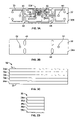
- FIG. 1 is a perspective illustration of the illumination system, including coupling between system modules constructed in accordance with the principles of the present invention.
- FIG. 2A is an enlarged perspective illustration of a module as depicted in FIG. 1 .
- FIG. 2B is an enlarged perspective illustration of a printed circuit board of the module, without the presence of a protective plastic cover for illustrative purposes.
- FIG. 3A is a top plan view of the printed circuit board showing a copper trace pattern.
- FIG. 3B is a bottom plan view of the printed circuit board.
- FIG. 3C is an elevation side view of the horizontal plane of the printed circuit board showing the various layers of the board.
- FIG. 3D is an elevation end view of the printed circuit depicting the layers of the board.
- FIG. 4A is a sectional view of a heat sink mass of the module.
- FIG. 4B is an elevation side view of the heat sink mass.
- FIG. 4C is a top plan view of the heat sink mass.
- FIG. 5 is a sectional view of the module, including the cover, constructed in accordance with the principles of the present invention.
- FIG. 1 With reference now to the drawings, and in particular to FIG. 1 thereof, the preferred embodiment of the new and improved illumination system embodying the principles and concepts of the present invention and generally designated by the reference numeral 10 will be described.
- the illumination system 10 is comprised of a plurality of components.
- Such components in their broadest context include a module 12 having a printed circuit board assembly 32 , a plurality of electrical components 37 , a pair of conductor wires 56 and at least one pair of connectors 60 .
- Such components are individually configured and correlated with respect to each other so as to attain the desired objective.
- Each module 12 has a metallic heat sink mass 14 with an elongated upper component 16 and an elongated lower component 18 .
- Each upper component 16 includes a generally flat lower surface 16 a and upper surface 16 b with laterally spaced wiring channels 20 and a central longitudinal void 21 there between.
- Each upper component 16 also includes curved sides 16 c with outwardly extending fins 22 for heat sink purposes.
- Each lower component 18 has a lower surface 18 a with a longitudinal depressed area 24 with a foam tape 26 there within, and an upper surface 18 b coupled to the lower surface 16 a of the upper component 16 .
- Each lower component 18 has a length greater than the length of its associated upper component to form a mounting tab 28 with a mounting aperture 30 there through.
- Each module 12 also has a circuit board assembly 32 with a front face 34 and a back face 36 mounted on the upper surface 16 b of the upper component 16 .
- Each circuit board assembly 32 comprises a bottom layer 38 a fabricated from multi-layers of dissimilar material construction such as high grade steel, a second layer 38 b consisting of a dielectric coating, a third layer 38 c having a copper trace pattern 39 , a fourth layer 38 d consisting of an additional sandwiching dielectric coating, and a top or fifth layer 38 e of ceramic coating.
- Such electrical components 37 include two high-power, high-intensity light emitting diodes 40 , a light emitting diode driver control chip 41 , a single high-frequency cap filter 42 to abate “noise”, rectifying diodes 44 that convert electrical potential from AC to DC, surface mounted resistors 46 of specific values to regulate the electrical potential and illuminate the light emitting diodes 40 .
- Each circuit board 32 has two pairs of small holes 48 for the passage of insulation displacement connectors 60 and one pair of large holes 50 for machine screws to couple the circuit boards to the metallic mass.
- Each module 12 also has a translucent cap cover 52 positionable over the central extent 32 a of an associated circuit board 32 with a generally semi-cylindrical upper surface 52 a and lateral snap tabs 54 adapted to couple with its associated circuit board.
- Each wire 56 is coupled during operation to a potential source of alternating current and extends through aligned wiring channels 20 of the upper component 16 of the modules 12 .
- a cross cut channel 58 is formed in the upper component 16 for allowing the electrical components to couple with the wires 56 .
- pairs of electrically conductive insulation displacement connectors 60 extend through each of the circuit boards 32 in proximity to their ends with upper ends 62 coupled with the trace patterns and lower ends 64 extending into the cross cut channel 58 to frictionally affix, and electrically couple, the connectors 60 and the wires 56 .
- FIG. 1 is a perspective illustration of the coupling between system segments or modules 12 depicting a sectional view of a continuous, light emitting diode illumination system 10 constructed in accordance with the principles of the present invention.
- the individual lighting modules 12 are linked together in a linear fashion in parallel, by and affixed to, a pair of continuous insulated and stranded copper core conductor wires 56 .
- These modules 12 when coupled to a power supply (not shown), can operate and function as a lighting unit singularly or in plurality, only limited by the amount of electrical potential available from the power supply and the laws of physics pertaining to electricity.
- FIG. 2A is an enlarged perspective illustration of a segment 12 with the protective plastic cover 52 in place over the exposed electrical components 37 of the lighting device module 12 , otherwise referred to as a pod, which individually or in plurality, as depicted in FIG. 1 , constitutes a light source.
- FIG. 2B is and enlarged perspective illustration of the metal-core, ceramic coated printed circuit board 32 with all of the surface mounted electrical components 37 and light emitting diodes 40 affixed in the proper operational positions without the presence of the protective plastic cover 52 for illustrative purposes.
- the printed circuit board 32 has a rectangular configuration.
- the printed circuit board 32 has front 34 and back 36 faces.
- the metal-core, ceramic coated printed circuit board 32 has electrical elements 37 coupled to the front face 34 .
- the material for the bottom or metal-core layer 38 a is preferably a heat conductive metal selected from the class of conductive metals including steel, stainless steel, aluminum and the like.
- the electrical elements 37 further include two light emitting diodes 40 , a plurality of resistors 46 and a high-frequency “noise” filtering capacitor 42 .
- There is a plurality of associated rectifying diodes 44 There is a plurality of associated rectifying diodes 44 .
- the rectifying diodes 44 convert alternating current (AC) to direct current (DC).
- One pair of inverted electrical insulation displacement connectors is provided.
- a light emitting diode control driver chip 41 which functionally provides clean and regulated electrical potential to energize and illuminate the light emitting diodes 40 .
- An injection molded plastic cap/cover 52 is provided to cover the electrical elements from environmental detriments and intrusions. Quick-snap tabs 54 are molded into the cap 52 to frictionally attach the plastic cap/cover over the metal-core, ceramic coated printed circuit board 32 and onto the heat sink fins 22 .
- FIG. 3A is a top plan view of the metal-core, ceramic coated printed circuit board 32 showing the copper trace pattern 39 and the top view of the through-hole 50 positions for the machine screw to mechanically fasten the metal-core, ceramic coated printed circuit board 32 to the metal heat sink mass 14 shown in FIG. 4 . Additionally, FIG. 3A shows the positions of the through-hole 48 positions for the insertion of the insulation displacement connectors 60 so they may be affixed untraditionally and uniquely to the bottom layer 38 a of a single-sided metal-clad printed board 32 .
- FIG. 3B is a bottom plan view of the metal-core, ceramic coated printed circuit board 32 .
- FIG. 3C is a elevation side view of the horizontal plane of the metal-core, ceramic coated printed circuit board 32 depicting the layers 38 a–e incorporated in the manufacture of the metal-core, ceramic coated printed circuit board 32 which, as explained above, is comprised of a steel base substrate bottom layer 38 a , a dielectric coating second layer 38 b , a copper trace third layer 38 c , a dielectric coating layer 38 d , and a top dielectric ceramic coating or finishing layer 38 e .
- FIG. 3D is an elevation or sectional end view of the horizontal plane of the printed circuit board 32 depicting the five layers 38 a–e.
- FIG. 3A illustrates the front face 34 of the printed circuit board 32 showing the copper trace pattern 39 necessary for the electrical elements 37 , once attached, to function in the intended manner
- FIG. 3B shows the back face 36 of the metal-core, ceramic coated printed circuit board 32 . Illustrated are the pre-stamped holes 50 for attachment of the machine screws, and the inverted insulation displacement connector holes 48 .
- FIG. 3C Shown in FIG. 3C is a profile view of the metal-core, ceramic coated printed circuit board 32 which shows the layers 38 a–e that make up the substrate, that includes two dielectric coating layers 38 d, b that sandwich a copper trace layer 38 c .
- the bottom layer 38 a consists of a high-grade steel for rigidity, even thermal distribution and transfer.
- FIG. 3D is a sectional view with the same material and component description as FIG. 3C .
- FIG. 4A is a sectional view of the typical cross-section of the metal heat sink mass 14 specifically designed to dissipate heat, mechanically fasten to the metal-core, ceramic coated printed circuit board 32 , and allow for the positioning of the continuous insulated and stranded copper core conductor wires 56 in the appropriate wire channels 20 , including the fins 22 for heat dissipation, a cut out depression 24 in the base 18 of the device 14 for double-sided tape 26 for fastening, as well as a tabbed extension 28 with a pre-drilled hole 30 for optional mechanical fastening to a substrate.
- FIG. 4B is an elevation side view of the metal heat sink mass 14 specifically designed to dissipate heat, mechanically fasten to the metal-core, ceramic coated printed circuit board 32 , and allow for the positioning of the continuous insulated and stranded copper core conductor wires 56 in the appropriate wire channels 20 , including the fins 22 for heat dissipation, a cut out depression 24 in the base 18 of the device 14 for double-sided tape 26 for fastening as well as a tabbed extension 28 with a pre-drilled hole 30 for optional mechanical fastening to a substrate.
- a cross cut 58 to allow for a void area 58 a in order for the inverted insulation displacement connectors 60 to be placed on the bottom side or face 36 of the metal-core, ceramic coated printed circuit board 32 after it is mechanically fastened to the heat sink mass 14 .
- FIG. 4C is a top plan view of the metal heat sink mass 14 specifically designed to dissipate heat, mechanically fasten to the metal-core, ceramic coated printed circuit board 32 , and allow for the positioning of the insulated and stranded copper core conductor wires 56 in the appropriate wire channels 20 , including the fins 22 for heat dissipation, a cut out depression 24 in the base 18 of the device 14 for double-sided tape 26 for fastening as well as a tabbed extension 28 with a pre-drilled hole 30 for optional mechanical fastening to a substrate.
- FIG. 4A A profile view of the specially designed metallic mass 14 is shown in FIG. 4A . It is used as a heat sink to dissipate heat energy created from the operation of a module 12 of the illumination system 10 into an attached substrate or ambient air by way of the air cooled fin 22 design present on both sides of the length of the heat sink mass 14 .
- Specific architecture is employed in the design of this device.
- Wiring channels 20 are provided to allow the continuous insulated conductor wires 56 to pass through the upper body component 16 of the heat sink mass 14 and fasten to the insulation displacement connectors 60 in a cross cut channel 58 in FIG. 4B and FIG. 4C .
- Mechanical fastening of the machine screw (not shown) through the hole 50 on the metal-core, ceramic coated printed circuit board 32 and into the specific void in the heat sink mass 14 allow for this during assembly
- FIGS. 4B and 4C show a cross-cut tab where the extruded body of the heat sink mass 14 has specifically been removed to create a mounting tab 28 , which has a pre-drilled hole 30 intended for mechanical fastening to a substrate or object by way a standard sized bolts and nuts, rivets, or screws.
- FIG. 5 is the end or sectional view the entire light emitting diode illumination module, pod, or unit 12 , constructed in accordance with the principles of the present invention and illustrating the primary embodiment of the invention. Additionally the double-sided adhesive foam tape 26 is depicted by a dashed rectangle in the depression area 24 of the heat sink mass 14 .
- the present invention allows significantly increased tolerances for electrical component configuration.
- the present invention has been configured to reduce operating temperature of the light emitting diodes 40 while maximizing the dissipation of ambient heat of the printed circuit board 32 created during its operation. This consideration further expands the range of applications this invention can be utilized in such as refrigeration environments where earlier forms of light emitting diode lighting systems maximized heat output, without consideration, to the detriment of the system component and/or the environment in which it is utilized.
Abstract
Description
Claims (33)
Priority Applications (2)
| Application Number | Priority Date | Filing Date | Title |
|---|---|---|---|
| US10/948,824 US7165863B1 (en) | 2004-09-23 | 2004-09-23 | Illumination system |
| US11/656,641 US7506995B2 (en) | 2004-09-23 | 2007-01-23 | Illumination system for use with display signage |
Applications Claiming Priority (1)
| Application Number | Priority Date | Filing Date | Title |
|---|---|---|---|
| US10/948,824 US7165863B1 (en) | 2004-09-23 | 2004-09-23 | Illumination system |
Related Child Applications (1)
| Application Number | Title | Priority Date | Filing Date |
|---|---|---|---|
| US11/656,641 Continuation US7506995B2 (en) | 2004-09-23 | 2007-01-23 | Illumination system for use with display signage |
Publications (1)
| Publication Number | Publication Date |
|---|---|
| US7165863B1 true US7165863B1 (en) | 2007-01-23 |
Family
ID=37663574
Family Applications (2)
| Application Number | Title | Priority Date | Filing Date |
|---|---|---|---|
| US10/948,824 Active 2024-10-06 US7165863B1 (en) | 2004-09-23 | 2004-09-23 | Illumination system |
| US11/656,641 Active US7506995B2 (en) | 2004-09-23 | 2007-01-23 | Illumination system for use with display signage |
Family Applications After (1)
| Application Number | Title | Priority Date | Filing Date |
|---|---|---|---|
| US11/656,641 Active US7506995B2 (en) | 2004-09-23 | 2007-01-23 | Illumination system for use with display signage |
Country Status (1)
| Country | Link |
|---|---|
| US (2) | US7165863B1 (en) |
Cited By (115)
| Publication number | Priority date | Publication date | Assignee | Title |
|---|---|---|---|---|
| US20060181878A1 (en) * | 2005-02-17 | 2006-08-17 | Federal-Mogul World Wide, Inc. | LED light module assembly |
| US20070053209A1 (en) * | 2005-09-06 | 2007-03-08 | Uhler George J | Low voltage lighting assembly and system |
| US20070056620A1 (en) * | 2005-09-12 | 2007-03-15 | Bahr Christopher J | Power connection for a thin film thermoelectric cooler |
| US20070208289A1 (en) * | 2006-03-03 | 2007-09-06 | Jay Walther | Systems and methods for providing light therapy traction |
| US20070208396A1 (en) * | 2006-03-03 | 2007-09-06 | Gary Whatcott | Systems and methods for providing a dynamic light pad |
| US20080025022A1 (en) * | 2004-01-30 | 2008-01-31 | Stephan Schinzel | Deformable Illumination Module |
| US20080036397A1 (en) * | 2006-04-21 | 2008-02-14 | Patent-Treuhand-Gesellschaft Fur Elektrische Gluhlampen Mbh | Modular lighting system and lighting arrangement |
| US20080055915A1 (en) * | 2003-09-22 | 2008-03-06 | Permlight Products, Inc. | Lighting apparatus |
| US20080080189A1 (en) * | 2006-09-29 | 2008-04-03 | Pei-Choa Wang | LED Illumination Apparatus |
| US20080107422A1 (en) * | 2006-11-08 | 2008-05-08 | Finisar Corporation | Serializer/deserializers for use in optoelectronic devices |
| EP1945007A1 (en) * | 2007-01-11 | 2008-07-16 | Schreder | Performance optimisation method of LED lighting devices |
| US20080169766A1 (en) * | 2007-01-11 | 2008-07-17 | Everlight Electronics Co., Ltd. | Alternating light emitting diode device |
| US20080192462A1 (en) * | 2007-02-14 | 2008-08-14 | James Steedly | Strip illumination device |
| US20080232103A1 (en) * | 2007-03-19 | 2008-09-25 | Lumination, Llc | Flexible LED lighting strips |
| US20080232105A1 (en) * | 2007-03-19 | 2008-09-25 | Lumination, Llc | Sealed lighting units |
| US20090021529A1 (en) * | 2004-10-14 | 2009-01-22 | Daktronics, Inc. | Flexible pixel element fabrication and sealing method |
| US20090021532A1 (en) * | 2004-10-14 | 2009-01-22 | Gloege Chad N | Translation table |
| US20090021497A1 (en) * | 2004-10-14 | 2009-01-22 | Daktronics, Inc. | Flexible pixel element and signal distribution means |
| US20090045428A1 (en) * | 2007-08-16 | 2009-02-19 | Lin Peter P W | Polarless surface mounting light emitting diode |
| US20090101921A1 (en) * | 2007-10-17 | 2009-04-23 | Tai-Sol Electronics Co., Ltd. | LED and thermal conductivity device combination assembly |
| WO2009036934A3 (en) * | 2007-09-14 | 2009-05-28 | Osram Gmbh | Illumination module |
| US20090147509A1 (en) * | 2007-12-07 | 2009-06-11 | Reed Daniel P | Configurable led lighting strip |
| WO2009077177A1 (en) * | 2007-12-18 | 2009-06-25 | Osram Opto Semiconductors Gmbh | Optoelectronic module and illumination device |
| US20090207608A1 (en) * | 2006-10-11 | 2009-08-20 | Morton Graham | lighting device |
| US20090219713A1 (en) * | 2008-03-02 | 2009-09-03 | Altair Engineering, Inc. | Lens and heatsink assembly for a led light tube |
| US20090279298A1 (en) * | 2008-05-06 | 2009-11-12 | Koninklijke Philips Electronics, N.V | Movable led track luminaire |
| EP2133620A1 (en) * | 2008-06-13 | 2009-12-16 | Adolf Maier | Light diode chain |
| EP2137772A1 (en) * | 2007-04-16 | 2009-12-30 | LG Innotek Co., Ltd. | Light source device and display device having the same |
| US20100046222A1 (en) * | 2008-08-22 | 2010-02-25 | Yang Fong-Ying | Light emitting diode lamp tube |
| US20100046220A1 (en) * | 2005-04-14 | 2010-02-25 | Koichi Fukasawa | Led unit and led lighting lamp using the led unit |
| US20100080003A1 (en) * | 2008-09-29 | 2010-04-01 | Han-Ming Lee | Radiating cold light polymer lamp structure |
| US20100103657A1 (en) * | 2008-10-24 | 2010-04-29 | Chien-Chen Teng | Custom assembly light-emitting module |
| US20100127639A1 (en) * | 2008-11-24 | 2010-05-27 | Jin Gil Cha | Led illumination module |
| US20100176724A1 (en) * | 2009-01-09 | 2010-07-15 | Neal Andrew T | LED Tubular Lighting Fixture |
| US20100203757A1 (en) * | 2009-02-06 | 2010-08-12 | Tyco Electronics Corporation | Jumper connector for a lighting assembly |
| US20100226139A1 (en) * | 2008-12-05 | 2010-09-09 | Permlight Products, Inc. | Led-based light engine |
| US7832896B2 (en) | 2008-04-18 | 2010-11-16 | Lumination Llc | LED light engine |
| US20100289418A1 (en) * | 2009-05-14 | 2010-11-18 | Altair Engineering, Inc. | Electronic circuit for dc conversion of fluorescent lighting ballast |
| US20100301729A1 (en) * | 2009-06-02 | 2010-12-02 | Altair Engineering, Inc. | Screw-in led bulb |
| US20100327752A1 (en) * | 2008-02-09 | 2010-12-30 | Sharp Kabushiki Kaisha | Light source unit, lighting apparatus and notice bearing apparatus |
| US7918591B2 (en) | 2005-05-13 | 2011-04-05 | Permlight Products, Inc. | LED-based luminaire |
| US7926975B2 (en) | 2007-12-21 | 2011-04-19 | Altair Engineering, Inc. | Light distribution using a light emitting diode assembly |
| US7938562B2 (en) | 2008-10-24 | 2011-05-10 | Altair Engineering, Inc. | Lighting including integral communication apparatus |
| US7946729B2 (en) | 2008-07-31 | 2011-05-24 | Altair Engineering, Inc. | Fluorescent tube replacement having longitudinally oriented LEDs |
| US7976196B2 (en) | 2008-07-09 | 2011-07-12 | Altair Engineering, Inc. | Method of forming LED-based light and resulting LED-based light |
| US20110194284A1 (en) * | 2008-12-12 | 2011-08-11 | The Sloan Company, Inc. Dba Sloanled | Channel letter lighting system using high output white light emitting diodes |
| US20110209368A1 (en) * | 2008-12-12 | 2011-09-01 | The Sloan Company, Inc. Dba Sloanled | Angled emitter channel letter lighting |
| CN102200229A (en) * | 2010-03-23 | 2011-09-28 | 洋鑫科技股份有限公司 | Light-emitting diode (LED) lamp tube |
| US20110234076A1 (en) * | 2010-03-26 | 2011-09-29 | Altair Engineering, Inc. | Inside-out led bulb |
| US8106923B2 (en) | 2004-10-14 | 2012-01-31 | Daktronics, Inc. | Flexible pixel hardware and method |
| US8118447B2 (en) | 2007-12-20 | 2012-02-21 | Altair Engineering, Inc. | LED lighting apparatus with swivel connection |
| US20120147596A1 (en) * | 2010-12-14 | 2012-06-14 | Osram Ag | Lamp having a tubular lamp body, method for production of a lamp such as this, and a spacing element |
| US8214084B2 (en) | 2008-10-24 | 2012-07-03 | Ilumisys, Inc. | Integration of LED lighting with building controls |
| US8256924B2 (en) | 2008-09-15 | 2012-09-04 | Ilumisys, Inc. | LED-based light having rapidly oscillating LEDs |
| US8324817B2 (en) | 2008-10-24 | 2012-12-04 | Ilumisys, Inc. | Light and light sensor |
| US8362710B2 (en) | 2009-01-21 | 2013-01-29 | Ilumisys, Inc. | Direct AC-to-DC converter for passive component minimization and universal operation of LED arrays |
| US8360599B2 (en) | 2008-05-23 | 2013-01-29 | Ilumisys, Inc. | Electric shock resistant L.E.D. based light |
| EP2564112A2 (en) * | 2010-04-27 | 2013-03-06 | Cooper Technologies Company | Linkable linear light emitting diode system |
| US8421366B2 (en) | 2009-06-23 | 2013-04-16 | Ilumisys, Inc. | Illumination device including LEDs and a switching power control system |
| WO2013068714A1 (en) * | 2011-11-07 | 2013-05-16 | David Morgan | Lighting arrangements |
| US8444292B2 (en) | 2008-10-24 | 2013-05-21 | Ilumisys, Inc. | End cap substitute for LED-based tube replacement light |
| US8454193B2 (en) | 2010-07-08 | 2013-06-04 | Ilumisys, Inc. | Independent modules for LED fluorescent light tube replacement |
| US20130188357A1 (en) * | 2008-12-12 | 2013-07-25 | The Sloan Company, Inc. Dba Sloanled | Channel letter lighting system using high output white light emitting diodes |
| US8523394B2 (en) | 2010-10-29 | 2013-09-03 | Ilumisys, Inc. | Mechanisms for reducing risk of shock during installation of light tube |
| WO2013135527A1 (en) * | 2012-03-13 | 2013-09-19 | Osram Gmbh | Light-emitting diode lamp and method for producing a light-emitting diode lamp |
| US8541958B2 (en) | 2010-03-26 | 2013-09-24 | Ilumisys, Inc. | LED light with thermoelectric generator |
| US8556452B2 (en) | 2009-01-15 | 2013-10-15 | Ilumisys, Inc. | LED lens |
| US8596813B2 (en) | 2010-07-12 | 2013-12-03 | Ilumisys, Inc. | Circuit board mount for LED light tube |
| US20140016298A1 (en) * | 2012-07-16 | 2014-01-16 | The Sloan Company, Inc. Dba Sloanled | Flexible ribbon led module |
| US8653984B2 (en) | 2008-10-24 | 2014-02-18 | Ilumisys, Inc. | Integration of LED lighting control with emergency notification systems |
| US8664880B2 (en) | 2009-01-21 | 2014-03-04 | Ilumisys, Inc. | Ballast/line detection circuit for fluorescent replacement lamps |
| US8674626B2 (en) | 2008-09-02 | 2014-03-18 | Ilumisys, Inc. | LED lamp failure alerting system |
| US20140254140A1 (en) * | 2006-10-05 | 2014-09-11 | GE Lighting Solutions, LLC | Led backlight system for cabinet sign |
| US8870415B2 (en) | 2010-12-09 | 2014-10-28 | Ilumisys, Inc. | LED fluorescent tube replacement light with reduced shock hazard |
| US8901823B2 (en) | 2008-10-24 | 2014-12-02 | Ilumisys, Inc. | Light and light sensor |
| US20140376226A1 (en) * | 2013-06-19 | 2014-12-25 | Artled Technology Corp. | Led light for a light box sign |
| US9057493B2 (en) | 2010-03-26 | 2015-06-16 | Ilumisys, Inc. | LED light tube with dual sided light distribution |
| US9072171B2 (en) | 2011-08-24 | 2015-06-30 | Ilumisys, Inc. | Circuit board mount for LED light |
| US9151454B1 (en) * | 2013-09-09 | 2015-10-06 | Automated Assembly Corporation | Modular LED lighting apparatus |
| US9163794B2 (en) | 2012-07-06 | 2015-10-20 | Ilumisys, Inc. | Power supply assembly for LED-based light tube |
| US9170000B2 (en) | 2008-12-12 | 2015-10-27 | The Sloan Company, Inc. | Angled emitter channel letter lighting |
| US9184518B2 (en) | 2012-03-02 | 2015-11-10 | Ilumisys, Inc. | Electrical connector header for an LED-based light |
| US9271367B2 (en) | 2012-07-09 | 2016-02-23 | Ilumisys, Inc. | System and method for controlling operation of an LED-based light |
| US9267650B2 (en) | 2013-10-09 | 2016-02-23 | Ilumisys, Inc. | Lens for an LED-based light |
| US9285084B2 (en) | 2013-03-14 | 2016-03-15 | Ilumisys, Inc. | Diffusers for LED-based lights |
| US9318475B2 (en) * | 2014-05-15 | 2016-04-19 | LuxVue Technology Corporation | Flexible display and method of formation with sacrificial release layer |
| US9464780B2 (en) | 2013-03-15 | 2016-10-11 | General Led, Inc. | LED light engine for signage |
| US9510400B2 (en) | 2014-05-13 | 2016-11-29 | Ilumisys, Inc. | User input systems for an LED-based light |
| US9506609B1 (en) * | 2014-03-19 | 2016-11-29 | System Lighting Solutions, Llc | Light system and method of installing |
| US9518706B2 (en) | 2009-11-12 | 2016-12-13 | Cooper Technologies Company | Linear LED light module |
| US9574717B2 (en) | 2014-01-22 | 2017-02-21 | Ilumisys, Inc. | LED-based light with addressed LEDs |
| US9626884B2 (en) | 2013-03-15 | 2017-04-18 | General Led, Inc. | LED light engine for signage |
| USD786493S1 (en) | 2016-01-28 | 2017-05-09 | Ericson Manufacturing Co. | String light |
| US20170159898A1 (en) * | 2015-12-02 | 2017-06-08 | Zyntony, Inc. | Multi-element flexible strap light |
| US20180014373A1 (en) * | 2016-07-06 | 2018-01-11 | Lumileds Llc | Printed circuit board for integrated led driver |
| USD810354S1 (en) | 2016-06-28 | 2018-02-13 | Tye T. Farnsworth | Light assembly |
| USD811648S1 (en) | 2016-06-28 | 2018-02-27 | System Lighting Solutions, Llc | Lens for lights |
| CN107893976A (en) * | 2017-10-26 | 2018-04-10 | 佛山市幻实科技有限公司 | A kind of LED connector |
| USD816889S1 (en) | 2016-06-28 | 2018-05-01 | System Lighting Solutions, Llc | Track assembly for lights |
| USD823496S1 (en) | 2016-06-28 | 2018-07-17 | System Lighting Solutions, Llc | Light and track assembly |
| USD835305S1 (en) | 2016-06-28 | 2018-12-04 | System Lighting Solutions, Llc | Light and track assembly |
| WO2018052391A3 (en) * | 2016-09-14 | 2018-12-06 | Tmt Reklam Endustri San. Tic. A. S. | Led module |
| US10161568B2 (en) | 2015-06-01 | 2018-12-25 | Ilumisys, Inc. | LED-based light with canted outer walls |
| US10217387B2 (en) | 2013-03-15 | 2019-02-26 | General Led Opco, Llc | LED light engine for signage |
| US20190145608A1 (en) * | 2017-11-10 | 2019-05-16 | General Led Opco, Llc | LED Light Engine |
| US10375791B2 (en) | 2014-03-19 | 2019-08-06 | System Lighting Solutions, Llc | Lighting system and method of installing |
| US10393354B2 (en) | 2016-10-28 | 2019-08-27 | Andrew Michael Schneider | Light assembly and alignment device |
| US10451227B2 (en) | 2015-01-28 | 2019-10-22 | Ericson Manufacturing Co. | String light |
| US10655823B1 (en) | 2019-02-04 | 2020-05-19 | Automated Assembly Corporation | SSL lighting apparatus |
| US10995931B1 (en) | 2020-08-06 | 2021-05-04 | Automated Assembly Corporation | SSL lighting apparatus |
| US11109693B2 (en) * | 2019-11-20 | 2021-09-07 | Self Electronics Co., Ltd. | Shelf lighting system, a laminate equipped with the lighting system and a shelf thereto |
| US11133627B2 (en) | 2018-11-09 | 2021-09-28 | Herman Miller, Inc. | Power distribution system |
| US11346538B1 (en) * | 2021-05-17 | 2022-05-31 | Sikai Chen | LED lighting module with electrical power and data connections |
| US11480322B1 (en) * | 2021-12-13 | 2022-10-25 | Sikai Chen | Magnetic signage lighting system |
| US11959603B2 (en) | 2023-10-31 | 2024-04-16 | Zyntony, Inc. | Multi-element flexible strap light |
Families Citing this family (33)
| Publication number | Priority date | Publication date | Assignee | Title |
|---|---|---|---|---|
| WO2007097262A1 (en) * | 2006-02-20 | 2007-08-30 | Stanley Electric Co., Ltd. | Illumination device |
| US20090086491A1 (en) | 2007-09-28 | 2009-04-02 | Ruud Lighting, Inc. | Aerodynamic LED Floodlight Fixture |
| US9028087B2 (en) | 2006-09-30 | 2015-05-12 | Cree, Inc. | LED light fixture |
| US9441824B2 (en) | 2008-04-04 | 2016-09-13 | Cree, Inc. | LED light fixture with heat-dissipation-related high light output |
| US7686469B2 (en) | 2006-09-30 | 2010-03-30 | Ruud Lighting, Inc. | LED lighting fixture |
| TWM334269U (en) * | 2007-12-07 | 2008-06-11 | Cooler Master Co Ltd | Light-emitting diode (LED) lighting device and lighting module having device |
| US8558755B2 (en) * | 2007-12-11 | 2013-10-15 | Adti Media, Llc140 | Large scale LED display system |
| US8766880B2 (en) * | 2007-12-11 | 2014-07-01 | Adti Media, Llc140 | Enumeration system and method for a LED display |
| US8922458B2 (en) * | 2007-12-11 | 2014-12-30 | ADTI Media, LLC | Data and power distribution system and method for a large scale display |
| US8599108B2 (en) * | 2007-12-11 | 2013-12-03 | Adti Media, Llc140 | Large scale LED display |
| US8648774B2 (en) * | 2007-12-11 | 2014-02-11 | Advance Display Technologies, Inc. | Large scale LED display |
| DE102007062047A1 (en) * | 2007-12-21 | 2009-07-16 | Osram Opto Semiconductors Gmbh | compact housing |
| US7726840B2 (en) * | 2008-03-04 | 2010-06-01 | Tempo Industries, Inc. | Modular LED lighting fixtures |
| CN201190978Y (en) * | 2008-03-25 | 2009-02-04 | 王保亮 | Backlight light source module |
| BRPI0910962B1 (en) | 2008-04-04 | 2019-05-28 | Cree, Inc | LED LIGHTING APPLIANCE |
| USRE49637E1 (en) | 2008-04-04 | 2023-08-29 | Ideal Industries Lighting Llc | Systems and methods for high output, high color quality light |
| TWI414713B (en) * | 2008-11-24 | 2013-11-11 | Everlight Electronics Co Ltd | Led lamp device manufacturing method |
| KR20100106790A (en) * | 2009-03-24 | 2010-10-04 | 삼성전자주식회사 | Display device |
| US8308320B2 (en) * | 2009-11-12 | 2012-11-13 | Cooper Technologies Company | Light emitting diode modules with male/female features for end-to-end coupling |
| KR101283867B1 (en) * | 2010-05-14 | 2013-07-08 | 엘지이노텍 주식회사 | Light-emitting element array, Backlight apparatus, and Illumination apparatus |
| CN201909192U (en) * | 2010-09-26 | 2011-07-27 | 邓建伟 | Improved LED (light-emitting diode) module |
| USD673720S1 (en) | 2010-10-07 | 2013-01-01 | Hubbell Incorporated | Luminaire housing |
| US9523491B2 (en) | 2010-10-07 | 2016-12-20 | Hubbell Incorporated | LED luminaire having lateral cooling fins and adaptive LED assembly |
| AT12903U1 (en) * | 2011-02-18 | 2013-01-15 | Zumtobel Lighting Gmbh | FAÇADE LIGHT WITH LIGHT DIODES |
| US8632213B2 (en) | 2011-05-05 | 2014-01-21 | Cree, Inc. | Lighting fixture with flow-through cooling |
| US8545045B2 (en) * | 2011-07-12 | 2013-10-01 | Rev-A-Shelf Company, Llc | Modular LED lighting systems and kits |
| JP6264568B2 (en) * | 2013-08-06 | 2018-01-24 | パナソニックIpマネジメント株式会社 | Light emitting device and display device |
| US9273833B2 (en) | 2013-11-01 | 2016-03-01 | Cree, Inc. | LED light fixtures with arrangement for electrical connection |
| WO2015093694A1 (en) * | 2013-12-20 | 2015-06-25 | 주식회사 필룩스 | Lighting device |
| US10584831B2 (en) | 2015-06-04 | 2020-03-10 | Eaton Intelligent Power Limited | Luminaire for use in harsh and hazardous locations |
| CA2987062C (en) * | 2015-06-04 | 2023-08-15 | Cooper Technologies Company | Linear led luminaire for use in harsh and hazardous locations |
| DE102017100165A1 (en) | 2017-01-05 | 2018-07-05 | Jabil Optics Germany GmbH | Light-emitting device and light-emitting system |
| US10823388B2 (en) | 2019-03-07 | 2020-11-03 | Current Lighting Solutions, Llc | Pressure equalized lighting subassembly |
Citations (41)
| Publication number | Priority date | Publication date | Assignee | Title |
|---|---|---|---|---|
| US3936686A (en) | 1973-05-07 | 1976-02-03 | Moore Donald W | Reflector lamp cooling and containing assemblies |
| US4143411A (en) | 1977-01-07 | 1979-03-06 | Roberts Thomas E | Architectural lighting apparatus |
| US4149217A (en) | 1977-07-26 | 1979-04-10 | Rangaire Corporation | Touch control panel for induction heating cook-top |
| US4416411A (en) | 1982-06-10 | 1983-11-22 | Container Corporation Of America | Sleeve-type carton for tapered articles |
| US4612206A (en) | 1984-06-04 | 1986-09-16 | Nisshin Steel Company, Ltd. | Method of controlling deposition amount distribution in a vacuum deposition plating |
| US4612606A (en) | 1985-04-01 | 1986-09-16 | Roberts James R | Apparatus for indirect lighting of stairs |
| US4720773A (en) | 1986-05-27 | 1988-01-19 | Ahroni Joseph M | Decorative light assembly |
| US4855882A (en) | 1988-03-29 | 1989-08-08 | Lightgraphix Limited | Lighting apparatus |
| US4908743A (en) | 1989-06-15 | 1990-03-13 | Miller Jack V | Strip lighting assembly |
| US5015918A (en) | 1988-07-22 | 1991-05-14 | John Copeland | Bicycle single-wire lighting system with steady-flashing-reflector rear warning device |
| US5103382A (en) | 1990-08-07 | 1992-04-07 | Stanley Electric Company | Auxiliary stop lamps |
| US5222799A (en) | 1990-08-21 | 1993-06-29 | Diamond Stairlight Industries | Stair lights |
| US5499170A (en) | 1994-10-18 | 1996-03-12 | Gagne; Bertrand | Lighting system |
| US5526236A (en) | 1994-07-27 | 1996-06-11 | General Signal Corporation | Lighting device used in an exit sign |
| US5607227A (en) | 1993-08-27 | 1997-03-04 | Sanyo Electric Co., Ltd. | Linear light source |
| US5697175A (en) | 1993-10-12 | 1997-12-16 | Spectralight, Inc. | Low power drain illuminated sign |
| US5746497A (en) | 1995-06-09 | 1998-05-05 | Koito Manufacturing Co., Ltd. | Automotive signal lamps |
| US5857767A (en) | 1996-09-23 | 1999-01-12 | Relume Corporation | Thermal management system for L.E.D. arrays |
| US5892192A (en) | 1995-10-23 | 1999-04-06 | Kabushiki Kaisha Tokai Rika Denki Seisakusho | Operation device for vehicle air conditioner |
| US5924785A (en) | 1997-05-21 | 1999-07-20 | Zhang; Lu Xin | Light source arrangement |
| US5931577A (en) | 1996-10-01 | 1999-08-03 | Atex Corporation Co., Ltd. | Display device and method for making the same |
| US6045240A (en) | 1996-06-27 | 2000-04-04 | Relume Corporation | LED lamp assembly with means to conduct heat away from the LEDS |
| US6072280A (en) | 1998-08-28 | 2000-06-06 | Fiber Optic Designs, Inc. | Led light string employing series-parallel block coupling |
| US6116748A (en) | 1998-06-17 | 2000-09-12 | Permlight Products, Inc. | Aisle lighting system |
| US6167648B1 (en) | 1998-02-23 | 2001-01-02 | Frederick Dimmick | Illuminated modular sign having adjustable quick release modules |
| US6183104B1 (en) | 1998-02-18 | 2001-02-06 | Dennis Ferrara | Decorative lighting system |
| US6244728B1 (en) | 1999-12-13 | 2001-06-12 | The Boeing Company | Light emitting diode assembly for use as an aircraft position light |
| US20010015891A1 (en) | 2000-02-18 | 2001-08-23 | Minebea Co., Ltd. | FPC for mounting components and spread illuminating apparatus using the same |
| US6283612B1 (en) | 2000-03-13 | 2001-09-04 | Mark A. Hunter | Light emitting diode light strip |
| US6346777B1 (en) | 2000-11-03 | 2002-02-12 | Ledart Co., Ltd. | Led lamp apparatus |
| US6350039B1 (en) | 2000-10-06 | 2002-02-26 | Lee Chien-Yu | Wall switch and lamp assembly |
| US6371637B1 (en) | 1999-02-26 | 2002-04-16 | Radiantz, Inc. | Compact, flexible, LED array |
| US6394626B1 (en) | 2000-04-11 | 2002-05-28 | Lumileds Lighting, U.S., Llc | Flexible light track for signage |
| US6396466B1 (en) | 1998-12-03 | 2002-05-28 | Agilent Technologies | Optical vehicle display |
| US6416200B1 (en) | 1996-11-25 | 2002-07-09 | Permlight Products, Inc. | Surface lighting system |
| US6431728B1 (en) | 2000-07-05 | 2002-08-13 | Whelen Engineering Company, Inc. | Multi-array LED warning lights |
| US6578986B2 (en) | 2001-06-29 | 2003-06-17 | Permlight Products, Inc. | Modular mounting arrangement and method for light emitting diodes |
| US6617520B1 (en) | 2000-08-30 | 2003-09-09 | Heatron, Inc. | Circuit board |
| US6665170B1 (en) | 2002-06-21 | 2003-12-16 | Bryan T. Warner | Light emitting diode illumination system |
| US6712486B1 (en) | 1999-10-19 | 2004-03-30 | Permlight Products, Inc. | Mounting arrangement for light emitting diodes |
| US6932495B2 (en) * | 2001-10-01 | 2005-08-23 | Sloanled, Inc. | Channel letter lighting using light emitting diodes |
-
2004
- 2004-09-23 US US10/948,824 patent/US7165863B1/en active Active
-
2007
- 2007-01-23 US US11/656,641 patent/US7506995B2/en active Active
Patent Citations (43)
| Publication number | Priority date | Publication date | Assignee | Title |
|---|---|---|---|---|
| US3936686A (en) | 1973-05-07 | 1976-02-03 | Moore Donald W | Reflector lamp cooling and containing assemblies |
| US4143411A (en) | 1977-01-07 | 1979-03-06 | Roberts Thomas E | Architectural lighting apparatus |
| US4149217A (en) | 1977-07-26 | 1979-04-10 | Rangaire Corporation | Touch control panel for induction heating cook-top |
| US4416411A (en) | 1982-06-10 | 1983-11-22 | Container Corporation Of America | Sleeve-type carton for tapered articles |
| US4612206A (en) | 1984-06-04 | 1986-09-16 | Nisshin Steel Company, Ltd. | Method of controlling deposition amount distribution in a vacuum deposition plating |
| US4612606A (en) | 1985-04-01 | 1986-09-16 | Roberts James R | Apparatus for indirect lighting of stairs |
| US4720773A (en) | 1986-05-27 | 1988-01-19 | Ahroni Joseph M | Decorative light assembly |
| US4855882A (en) | 1988-03-29 | 1989-08-08 | Lightgraphix Limited | Lighting apparatus |
| US5015918A (en) | 1988-07-22 | 1991-05-14 | John Copeland | Bicycle single-wire lighting system with steady-flashing-reflector rear warning device |
| US4908743A (en) | 1989-06-15 | 1990-03-13 | Miller Jack V | Strip lighting assembly |
| US5103382A (en) | 1990-08-07 | 1992-04-07 | Stanley Electric Company | Auxiliary stop lamps |
| US5222799A (en) | 1990-08-21 | 1993-06-29 | Diamond Stairlight Industries | Stair lights |
| US5607227A (en) | 1993-08-27 | 1997-03-04 | Sanyo Electric Co., Ltd. | Linear light source |
| US5697175A (en) | 1993-10-12 | 1997-12-16 | Spectralight, Inc. | Low power drain illuminated sign |
| US5526236A (en) | 1994-07-27 | 1996-06-11 | General Signal Corporation | Lighting device used in an exit sign |
| US5499170A (en) | 1994-10-18 | 1996-03-12 | Gagne; Bertrand | Lighting system |
| US5746497A (en) | 1995-06-09 | 1998-05-05 | Koito Manufacturing Co., Ltd. | Automotive signal lamps |
| US5892192A (en) | 1995-10-23 | 1999-04-06 | Kabushiki Kaisha Tokai Rika Denki Seisakusho | Operation device for vehicle air conditioner |
| US6045240A (en) | 1996-06-27 | 2000-04-04 | Relume Corporation | LED lamp assembly with means to conduct heat away from the LEDS |
| US5857767A (en) | 1996-09-23 | 1999-01-12 | Relume Corporation | Thermal management system for L.E.D. arrays |
| US5931577A (en) | 1996-10-01 | 1999-08-03 | Atex Corporation Co., Ltd. | Display device and method for making the same |
| US6416200B1 (en) | 1996-11-25 | 2002-07-09 | Permlight Products, Inc. | Surface lighting system |
| US5924785A (en) | 1997-05-21 | 1999-07-20 | Zhang; Lu Xin | Light source arrangement |
| US6183104B1 (en) | 1998-02-18 | 2001-02-06 | Dennis Ferrara | Decorative lighting system |
| US6167648B1 (en) | 1998-02-23 | 2001-01-02 | Frederick Dimmick | Illuminated modular sign having adjustable quick release modules |
| US6116748A (en) | 1998-06-17 | 2000-09-12 | Permlight Products, Inc. | Aisle lighting system |
| US6072280A (en) | 1998-08-28 | 2000-06-06 | Fiber Optic Designs, Inc. | Led light string employing series-parallel block coupling |
| US6396466B1 (en) | 1998-12-03 | 2002-05-28 | Agilent Technologies | Optical vehicle display |
| US6371637B1 (en) | 1999-02-26 | 2002-04-16 | Radiantz, Inc. | Compact, flexible, LED array |
| US6712486B1 (en) | 1999-10-19 | 2004-03-30 | Permlight Products, Inc. | Mounting arrangement for light emitting diodes |
| US6244728B1 (en) | 1999-12-13 | 2001-06-12 | The Boeing Company | Light emitting diode assembly for use as an aircraft position light |
| US20010015891A1 (en) | 2000-02-18 | 2001-08-23 | Minebea Co., Ltd. | FPC for mounting components and spread illuminating apparatus using the same |
| US6283612B1 (en) | 2000-03-13 | 2001-09-04 | Mark A. Hunter | Light emitting diode light strip |
| US6394626B1 (en) | 2000-04-11 | 2002-05-28 | Lumileds Lighting, U.S., Llc | Flexible light track for signage |
| US6431728B1 (en) | 2000-07-05 | 2002-08-13 | Whelen Engineering Company, Inc. | Multi-array LED warning lights |
| US6617520B1 (en) | 2000-08-30 | 2003-09-09 | Heatron, Inc. | Circuit board |
| US6350039B1 (en) | 2000-10-06 | 2002-02-26 | Lee Chien-Yu | Wall switch and lamp assembly |
| US6346777B1 (en) | 2000-11-03 | 2002-02-12 | Ledart Co., Ltd. | Led lamp apparatus |
| US6578986B2 (en) | 2001-06-29 | 2003-06-17 | Permlight Products, Inc. | Modular mounting arrangement and method for light emitting diodes |
| US20030218878A1 (en) | 2001-06-29 | 2003-11-27 | Permlight Products, Inc. | Modular mounting arrangement and method for light emitting diodes |
| US6846093B2 (en) | 2001-06-29 | 2005-01-25 | Permlight Products, Inc. | Modular mounting arrangement and method for light emitting diodes |
| US6932495B2 (en) * | 2001-10-01 | 2005-08-23 | Sloanled, Inc. | Channel letter lighting using light emitting diodes |
| US6665170B1 (en) | 2002-06-21 | 2003-12-16 | Bryan T. Warner | Light emitting diode illumination system |
Cited By (205)
| Publication number | Priority date | Publication date | Assignee | Title |
|---|---|---|---|---|
| US8079731B2 (en) | 2003-09-22 | 2011-12-20 | Permlight Products, Inc. | Lighting apparatus |
| US20080055915A1 (en) * | 2003-09-22 | 2008-03-06 | Permlight Products, Inc. | Lighting apparatus |
| US20080025022A1 (en) * | 2004-01-30 | 2008-01-31 | Stephan Schinzel | Deformable Illumination Module |
| US7926976B2 (en) * | 2004-01-30 | 2011-04-19 | Osram Opto Semiconductors Gmbh | Deformable illumination module |
| US8552929B2 (en) | 2004-10-14 | 2013-10-08 | Daktronics, Inc. | Flexible pixel hardware and method |
| US8106923B2 (en) | 2004-10-14 | 2012-01-31 | Daktronics, Inc. | Flexible pixel hardware and method |
| US8552928B2 (en) | 2004-10-14 | 2013-10-08 | Daktronics, Inc. | Sealed pixel assemblies, kits and methods |
| US20090021497A1 (en) * | 2004-10-14 | 2009-01-22 | Daktronics, Inc. | Flexible pixel element and signal distribution means |
| US20090021529A1 (en) * | 2004-10-14 | 2009-01-22 | Daktronics, Inc. | Flexible pixel element fabrication and sealing method |
| US9052092B2 (en) | 2004-10-14 | 2015-06-09 | Daktronics, Inc. | Sealed pixel assemblies, kits and methods |
| US20090021532A1 (en) * | 2004-10-14 | 2009-01-22 | Gloege Chad N | Translation table |
| US8344410B2 (en) | 2004-10-14 | 2013-01-01 | Daktronics, Inc. | Flexible pixel element and signal distribution means |
| US7868903B2 (en) * | 2004-10-14 | 2011-01-11 | Daktronics, Inc. | Flexible pixel element fabrication and sealing method |
| US20110102307A1 (en) * | 2004-10-14 | 2011-05-05 | Daktronics, Inc. | Sealed pixel assemblies, kits and methods |
| US8001455B2 (en) | 2004-10-14 | 2011-08-16 | Daktronics, Inc. | Translation table |
| US8363038B2 (en) | 2004-10-14 | 2013-01-29 | Daktronics, Inc. | Flexible pixel hardware and method |
| US8604509B2 (en) | 2004-10-14 | 2013-12-10 | Daktronics, Inc. | Flexible pixel element and signal distribution means |
| US20060181878A1 (en) * | 2005-02-17 | 2006-08-17 | Federal-Mogul World Wide, Inc. | LED light module assembly |
| WO2006089033A2 (en) * | 2005-02-17 | 2006-08-24 | Federal-Mogul Corporation | Led light module assembly |
| WO2006089033A3 (en) * | 2005-02-17 | 2007-08-09 | Federal Mogul Corp | Led light module assembly |
| US7284882B2 (en) * | 2005-02-17 | 2007-10-23 | Federal-Mogul World Wide, Inc. | LED light module assembly |
| US8596820B2 (en) * | 2005-04-14 | 2013-12-03 | Citizen Electronics Co., Ltd. | LED unit and LED lighting lamp using the LED unit |
| US20100046220A1 (en) * | 2005-04-14 | 2010-02-25 | Koichi Fukasawa | Led unit and led lighting lamp using the led unit |
| US7918591B2 (en) | 2005-05-13 | 2011-04-05 | Permlight Products, Inc. | LED-based luminaire |
| US7364346B2 (en) * | 2005-09-06 | 2008-04-29 | The L.D. Kichler Co. | Low voltage track lighting assembly and system |
| US20070053209A1 (en) * | 2005-09-06 | 2007-03-08 | Uhler George J | Low voltage lighting assembly and system |
| US20070056620A1 (en) * | 2005-09-12 | 2007-03-15 | Bahr Christopher J | Power connection for a thin film thermoelectric cooler |
| US20070208289A1 (en) * | 2006-03-03 | 2007-09-06 | Jay Walther | Systems and methods for providing light therapy traction |
| US20070208396A1 (en) * | 2006-03-03 | 2007-09-06 | Gary Whatcott | Systems and methods for providing a dynamic light pad |
| US7963669B2 (en) * | 2006-04-21 | 2011-06-21 | Osram Gesellschaft mit beschränkter Haftung | Modular lighting system and lighting arrangement |
| US20080036397A1 (en) * | 2006-04-21 | 2008-02-14 | Patent-Treuhand-Gesellschaft Fur Elektrische Gluhlampen Mbh | Modular lighting system and lighting arrangement |
| US20080080189A1 (en) * | 2006-09-29 | 2008-04-03 | Pei-Choa Wang | LED Illumination Apparatus |
| US7513639B2 (en) * | 2006-09-29 | 2009-04-07 | Pyroswift Holding Co., Limited | LED illumination apparatus |
| US9836999B2 (en) * | 2006-10-05 | 2017-12-05 | GE Lighting Solutions, LLC | LED backlight system for cabinet sign |
| US20140254140A1 (en) * | 2006-10-05 | 2014-09-11 | GE Lighting Solutions, LLC | Led backlight system for cabinet sign |
| US20150007469A1 (en) * | 2006-10-05 | 2015-01-08 | GE Lighting Solutions, LLC | Led backlight system for cabinet sign |
| US9165487B2 (en) * | 2006-10-05 | 2015-10-20 | GE Lighting Solutions, LLC | LED backlight system for cabinet sign |
| US20140317975A1 (en) * | 2006-10-05 | 2014-10-30 | GE Lighting Solutions, LLC | Led backlight system for cabinet sign |
| US10223944B2 (en) * | 2006-10-05 | 2019-03-05 | GE Lighting Solutions, LLC | LED backlight system for cabinet sign |
| US20090207608A1 (en) * | 2006-10-11 | 2009-08-20 | Morton Graham | lighting device |
| US8162515B2 (en) * | 2006-10-11 | 2012-04-24 | Morton Graham | Lighting device |
| US7860400B2 (en) | 2006-11-08 | 2010-12-28 | Finisar Corporation | Serializer/deserializers for use in optoelectronic devices |
| US20080107422A1 (en) * | 2006-11-08 | 2008-05-08 | Finisar Corporation | Serializer/deserializers for use in optoelectronic devices |
| US8174196B2 (en) * | 2007-01-11 | 2012-05-08 | Everlight Electronics Co., Ltd. | Alternating current light emitting diode device |
| US20080169766A1 (en) * | 2007-01-11 | 2008-07-17 | Everlight Electronics Co., Ltd. | Alternating light emitting diode device |
| EP1945007A1 (en) * | 2007-01-11 | 2008-07-16 | Schreder | Performance optimisation method of LED lighting devices |
| US20080192462A1 (en) * | 2007-02-14 | 2008-08-14 | James Steedly | Strip illumination device |
| US7815341B2 (en) | 2007-02-14 | 2010-10-19 | Permlight Products, Inc. | Strip illumination device |
| US7687288B2 (en) | 2007-03-19 | 2010-03-30 | Lumination Llc | Sealed lighting units |
| US20080232105A1 (en) * | 2007-03-19 | 2008-09-25 | Lumination, Llc | Sealed lighting units |
| US20080232103A1 (en) * | 2007-03-19 | 2008-09-25 | Lumination, Llc | Flexible LED lighting strips |
| US7931386B2 (en) | 2007-03-19 | 2011-04-26 | GE Lighting Solutions, LLC | Flexible LED lighting strips including overmolding encasement and attached parallel electrical conductors |
| EP2137772A1 (en) * | 2007-04-16 | 2009-12-30 | LG Innotek Co., Ltd. | Light source device and display device having the same |
| EP2137772A4 (en) * | 2007-04-16 | 2013-09-25 | Lg Innotek Co Ltd | Light source device and display device having the same |
| US7714334B2 (en) * | 2007-08-16 | 2010-05-11 | Lin Peter P W | Polarless surface mounting light emitting diode |
| US20090045428A1 (en) * | 2007-08-16 | 2009-02-19 | Lin Peter P W | Polarless surface mounting light emitting diode |
| US8657462B2 (en) | 2007-09-14 | 2014-02-25 | Osram Gesellschaft Mit Beschraenkter Haftung | Illumination module |
| WO2009036934A3 (en) * | 2007-09-14 | 2009-05-28 | Osram Gmbh | Illumination module |
| US20090101921A1 (en) * | 2007-10-17 | 2009-04-23 | Tai-Sol Electronics Co., Ltd. | LED and thermal conductivity device combination assembly |
| US20090147509A1 (en) * | 2007-12-07 | 2009-06-11 | Reed Daniel P | Configurable led lighting strip |
| WO2009077177A1 (en) * | 2007-12-18 | 2009-06-25 | Osram Opto Semiconductors Gmbh | Optoelectronic module and illumination device |
| US8928025B2 (en) | 2007-12-20 | 2015-01-06 | Ilumisys, Inc. | LED lighting apparatus with swivel connection |
| US8118447B2 (en) | 2007-12-20 | 2012-02-21 | Altair Engineering, Inc. | LED lighting apparatus with swivel connection |
| US7926975B2 (en) | 2007-12-21 | 2011-04-19 | Altair Engineering, Inc. | Light distribution using a light emitting diode assembly |
| US20100327752A1 (en) * | 2008-02-09 | 2010-12-30 | Sharp Kabushiki Kaisha | Light source unit, lighting apparatus and notice bearing apparatus |
| US8382326B2 (en) * | 2008-02-19 | 2013-02-26 | Sharp Kabushiki Kaisha | Light source unit, lighting apparatus and notice bearing apparatus |
| US20090219713A1 (en) * | 2008-03-02 | 2009-09-03 | Altair Engineering, Inc. | Lens and heatsink assembly for a led light tube |
| US7815338B2 (en) | 2008-03-02 | 2010-10-19 | Altair Engineering, Inc. | LED lighting unit including elongated heat sink and elongated lens |
| US7832896B2 (en) | 2008-04-18 | 2010-11-16 | Lumination Llc | LED light engine |
| US20090279298A1 (en) * | 2008-05-06 | 2009-11-12 | Koninklijke Philips Electronics, N.V | Movable led track luminaire |
| US8348492B2 (en) * | 2008-05-06 | 2013-01-08 | Koninklijke Philips Electronics N.V. | Movable LED track luminaire |
| US8360599B2 (en) | 2008-05-23 | 2013-01-29 | Ilumisys, Inc. | Electric shock resistant L.E.D. based light |
| US8807785B2 (en) | 2008-05-23 | 2014-08-19 | Ilumisys, Inc. | Electric shock resistant L.E.D. based light |
| EP2133620A1 (en) * | 2008-06-13 | 2009-12-16 | Adolf Maier | Light diode chain |
| US7976196B2 (en) | 2008-07-09 | 2011-07-12 | Altair Engineering, Inc. | Method of forming LED-based light and resulting LED-based light |
| US7946729B2 (en) | 2008-07-31 | 2011-05-24 | Altair Engineering, Inc. | Fluorescent tube replacement having longitudinally oriented LEDs |
| US20100046222A1 (en) * | 2008-08-22 | 2010-02-25 | Yang Fong-Ying | Light emitting diode lamp tube |
| US8674626B2 (en) | 2008-09-02 | 2014-03-18 | Ilumisys, Inc. | LED lamp failure alerting system |
| US8256924B2 (en) | 2008-09-15 | 2012-09-04 | Ilumisys, Inc. | LED-based light having rapidly oscillating LEDs |
| US20100080003A1 (en) * | 2008-09-29 | 2010-04-01 | Han-Ming Lee | Radiating cold light polymer lamp structure |
| US8444292B2 (en) | 2008-10-24 | 2013-05-21 | Ilumisys, Inc. | End cap substitute for LED-based tube replacement light |
| US9101026B2 (en) | 2008-10-24 | 2015-08-04 | Ilumisys, Inc. | Integration of LED lighting with building controls |
| US10182480B2 (en) | 2008-10-24 | 2019-01-15 | Ilumisys, Inc. | Light and light sensor |
| US10176689B2 (en) | 2008-10-24 | 2019-01-08 | Ilumisys, Inc. | Integration of led lighting control with emergency notification systems |
| US10036549B2 (en) | 2008-10-24 | 2018-07-31 | Ilumisys, Inc. | Lighting including integral communication apparatus |
| US10713915B2 (en) | 2008-10-24 | 2020-07-14 | Ilumisys, Inc. | Integration of LED lighting control with emergency notification systems |
| US8324817B2 (en) | 2008-10-24 | 2012-12-04 | Ilumisys, Inc. | Light and light sensor |
| US10932339B2 (en) | 2008-10-24 | 2021-02-23 | Ilumisys, Inc. | Light and light sensor |
| US10973094B2 (en) | 2008-10-24 | 2021-04-06 | Ilumisys, Inc. | Integration of LED lighting with building controls |
| US9635727B2 (en) | 2008-10-24 | 2017-04-25 | Ilumisys, Inc. | Light and light sensor |
| US9585216B2 (en) | 2008-10-24 | 2017-02-28 | Ilumisys, Inc. | Integration of LED lighting with building controls |
| US10560992B2 (en) | 2008-10-24 | 2020-02-11 | Ilumisys, Inc. | Light and light sensor |
| US9398661B2 (en) | 2008-10-24 | 2016-07-19 | Ilumisys, Inc. | Light and light sensor |
| US8901823B2 (en) | 2008-10-24 | 2014-12-02 | Ilumisys, Inc. | Light and light sensor |
| US9353939B2 (en) | 2008-10-24 | 2016-05-31 | iLumisys, Inc | Lighting including integral communication apparatus |
| US10571115B2 (en) | 2008-10-24 | 2020-02-25 | Ilumisys, Inc. | Lighting including integral communication apparatus |
| US8251544B2 (en) | 2008-10-24 | 2012-08-28 | Ilumisys, Inc. | Lighting including integral communication apparatus |
| US7938562B2 (en) | 2008-10-24 | 2011-05-10 | Altair Engineering, Inc. | Lighting including integral communication apparatus |
| US8214084B2 (en) | 2008-10-24 | 2012-07-03 | Ilumisys, Inc. | Integration of LED lighting with building controls |
| US8946996B2 (en) | 2008-10-24 | 2015-02-03 | Ilumisys, Inc. | Light and light sensor |
| US11073275B2 (en) | 2008-10-24 | 2021-07-27 | Ilumisys, Inc. | Lighting including integral communication apparatus |
| US11333308B2 (en) | 2008-10-24 | 2022-05-17 | Ilumisys, Inc. | Light and light sensor |
| US10342086B2 (en) | 2008-10-24 | 2019-07-02 | Ilumisys, Inc. | Integration of LED lighting with building controls |
| US8653984B2 (en) | 2008-10-24 | 2014-02-18 | Ilumisys, Inc. | Integration of LED lighting control with emergency notification systems |
| US20100103657A1 (en) * | 2008-10-24 | 2010-04-29 | Chien-Chen Teng | Custom assembly light-emitting module |
| US20100127639A1 (en) * | 2008-11-24 | 2010-05-27 | Jin Gil Cha | Led illumination module |
| US8167465B2 (en) * | 2008-11-24 | 2012-05-01 | Jinyoung I&C Co., Ltd | LED illumination module |
| US20100226139A1 (en) * | 2008-12-05 | 2010-09-09 | Permlight Products, Inc. | Led-based light engine |
| US8926145B2 (en) | 2008-12-05 | 2015-01-06 | Permlight Products, Inc. | LED-based light engine having thermally insulated zones |
| US9080745B2 (en) * | 2008-12-12 | 2015-07-14 | The Sloan Company, Inc. | Angled emitter channel letter lighting |
| US20110194284A1 (en) * | 2008-12-12 | 2011-08-11 | The Sloan Company, Inc. Dba Sloanled | Channel letter lighting system using high output white light emitting diodes |
| US20110209368A1 (en) * | 2008-12-12 | 2011-09-01 | The Sloan Company, Inc. Dba Sloanled | Angled emitter channel letter lighting |
| US9170000B2 (en) | 2008-12-12 | 2015-10-27 | The Sloan Company, Inc. | Angled emitter channel letter lighting |
| US20130188357A1 (en) * | 2008-12-12 | 2013-07-25 | The Sloan Company, Inc. Dba Sloanled | Channel letter lighting system using high output white light emitting diodes |
| US20100176724A1 (en) * | 2009-01-09 | 2010-07-15 | Neal Andrew T | LED Tubular Lighting Fixture |
| US8115393B2 (en) | 2009-01-09 | 2012-02-14 | Neal Andrew T | LED tubular lighting fixture |
| US8556452B2 (en) | 2009-01-15 | 2013-10-15 | Ilumisys, Inc. | LED lens |
| US8362710B2 (en) | 2009-01-21 | 2013-01-29 | Ilumisys, Inc. | Direct AC-to-DC converter for passive component minimization and universal operation of LED arrays |
| US8664880B2 (en) | 2009-01-21 | 2014-03-04 | Ilumisys, Inc. | Ballast/line detection circuit for fluorescent replacement lamps |
| JP2010182674A (en) * | 2009-02-06 | 2010-08-19 | Tyco Electronics Corp | Jumper connector for lighting assembly |
| US20100203757A1 (en) * | 2009-02-06 | 2010-08-12 | Tyco Electronics Corporation | Jumper connector for a lighting assembly |
| US7892022B2 (en) * | 2009-02-06 | 2011-02-22 | Tyco Electronics Corporation | Jumper connector for a lighting assembly |
| US8330381B2 (en) | 2009-05-14 | 2012-12-11 | Ilumisys, Inc. | Electronic circuit for DC conversion of fluorescent lighting ballast |
| US20100289418A1 (en) * | 2009-05-14 | 2010-11-18 | Altair Engineering, Inc. | Electronic circuit for dc conversion of fluorescent lighting ballast |
| US8299695B2 (en) | 2009-06-02 | 2012-10-30 | Ilumisys, Inc. | Screw-in LED bulb comprising a base having outwardly projecting nodes |
| US20100301729A1 (en) * | 2009-06-02 | 2010-12-02 | Altair Engineering, Inc. | Screw-in led bulb |
| US8421366B2 (en) | 2009-06-23 | 2013-04-16 | Ilumisys, Inc. | Illumination device including LEDs and a switching power control system |
| US9518706B2 (en) | 2009-11-12 | 2016-12-13 | Cooper Technologies Company | Linear LED light module |
| CN102200229A (en) * | 2010-03-23 | 2011-09-28 | 洋鑫科技股份有限公司 | Light-emitting diode (LED) lamp tube |
| CN102200229B (en) * | 2010-03-23 | 2013-01-23 | 洋鑫科技股份有限公司 | Light-emitting diode (LED) lamp tube |
| US9057493B2 (en) | 2010-03-26 | 2015-06-16 | Ilumisys, Inc. | LED light tube with dual sided light distribution |
| US8541958B2 (en) | 2010-03-26 | 2013-09-24 | Ilumisys, Inc. | LED light with thermoelectric generator |
| US9013119B2 (en) | 2010-03-26 | 2015-04-21 | Ilumisys, Inc. | LED light with thermoelectric generator |
| US8540401B2 (en) | 2010-03-26 | 2013-09-24 | Ilumisys, Inc. | LED bulb with internal heat dissipating structures |
| US20110234076A1 (en) * | 2010-03-26 | 2011-09-29 | Altair Engineering, Inc. | Inside-out led bulb |
| US9395075B2 (en) | 2010-03-26 | 2016-07-19 | Ilumisys, Inc. | LED bulb for incandescent bulb replacement with internal heat dissipating structures |
| US8840282B2 (en) | 2010-03-26 | 2014-09-23 | Ilumisys, Inc. | LED bulb with internal heat dissipating structures |
| EP2564112A4 (en) * | 2010-04-27 | 2014-12-31 | Cooper Technologies Co | Linkable linear light emitting diode system |
| US9285085B2 (en) | 2010-04-27 | 2016-03-15 | Cooper Technologies Company | LED lighting system with distributive powering scheme |
| EP2564112A2 (en) * | 2010-04-27 | 2013-03-06 | Cooper Technologies Company | Linkable linear light emitting diode system |
| US10006592B2 (en) | 2010-04-27 | 2018-06-26 | Cooper Technologies Company | LED lighting system with distributive powering scheme |
| US10648652B2 (en) | 2010-04-27 | 2020-05-12 | Eaton Intelligent Power Limited | LED lighting system with distributive powering scheme |
| US8454193B2 (en) | 2010-07-08 | 2013-06-04 | Ilumisys, Inc. | Independent modules for LED fluorescent light tube replacement |
| US8596813B2 (en) | 2010-07-12 | 2013-12-03 | Ilumisys, Inc. | Circuit board mount for LED light tube |
| US8894430B2 (en) | 2010-10-29 | 2014-11-25 | Ilumisys, Inc. | Mechanisms for reducing risk of shock during installation of light tube |
| US8523394B2 (en) | 2010-10-29 | 2013-09-03 | Ilumisys, Inc. | Mechanisms for reducing risk of shock during installation of light tube |
| US8870415B2 (en) | 2010-12-09 | 2014-10-28 | Ilumisys, Inc. | LED fluorescent tube replacement light with reduced shock hazard |
| US20120147596A1 (en) * | 2010-12-14 | 2012-06-14 | Osram Ag | Lamp having a tubular lamp body, method for production of a lamp such as this, and a spacing element |
| US8950891B2 (en) * | 2010-12-14 | 2015-02-10 | Osram Ag | Lamp having a tubular lamp body, method for production of a lamp such as this, and a spacing element |
| US9072171B2 (en) | 2011-08-24 | 2015-06-30 | Ilumisys, Inc. | Circuit board mount for LED light |
| CN104114943B (en) * | 2011-11-07 | 2018-03-20 | 大卫·摩根 | Lighting device |
| US9464770B2 (en) | 2011-11-07 | 2016-10-11 | David Morgan | LED lighting strip |
| WO2013068714A1 (en) * | 2011-11-07 | 2013-05-16 | David Morgan | Lighting arrangements |
| CN104114943A (en) * | 2011-11-07 | 2014-10-22 | 大卫·摩根 | Lighting arrangements |
| US9184518B2 (en) | 2012-03-02 | 2015-11-10 | Ilumisys, Inc. | Electrical connector header for an LED-based light |
| WO2013135527A1 (en) * | 2012-03-13 | 2013-09-19 | Osram Gmbh | Light-emitting diode lamp and method for producing a light-emitting diode lamp |
| US9163794B2 (en) | 2012-07-06 | 2015-10-20 | Ilumisys, Inc. | Power supply assembly for LED-based light tube |
| US9271367B2 (en) | 2012-07-09 | 2016-02-23 | Ilumisys, Inc. | System and method for controlling operation of an LED-based light |
| US9807842B2 (en) | 2012-07-09 | 2017-10-31 | Ilumisys, Inc. | System and method for controlling operation of an LED-based light |
| US20140016298A1 (en) * | 2012-07-16 | 2014-01-16 | The Sloan Company, Inc. Dba Sloanled | Flexible ribbon led module |
| US9285084B2 (en) | 2013-03-14 | 2016-03-15 | Ilumisys, Inc. | Diffusers for LED-based lights |
| US10217387B2 (en) | 2013-03-15 | 2019-02-26 | General Led Opco, Llc | LED light engine for signage |
| US9464780B2 (en) | 2013-03-15 | 2016-10-11 | General Led, Inc. | LED light engine for signage |
| US9626884B2 (en) | 2013-03-15 | 2017-04-18 | General Led, Inc. | LED light engine for signage |
| US20140376226A1 (en) * | 2013-06-19 | 2014-12-25 | Artled Technology Corp. | Led light for a light box sign |
| US9151454B1 (en) * | 2013-09-09 | 2015-10-06 | Automated Assembly Corporation | Modular LED lighting apparatus |
| US9267650B2 (en) | 2013-10-09 | 2016-02-23 | Ilumisys, Inc. | Lens for an LED-based light |
| US9574717B2 (en) | 2014-01-22 | 2017-02-21 | Ilumisys, Inc. | LED-based light with addressed LEDs |
| US10260686B2 (en) | 2014-01-22 | 2019-04-16 | Ilumisys, Inc. | LED-based light with addressed LEDs |
| US9506609B1 (en) * | 2014-03-19 | 2016-11-29 | System Lighting Solutions, Llc | Light system and method of installing |
| US9951914B1 (en) | 2014-03-19 | 2018-04-24 | System Lighting Solutions, Llc | Light system and method of installing |
| US10375791B2 (en) | 2014-03-19 | 2019-08-06 | System Lighting Solutions, Llc | Lighting system and method of installing |
| US9510400B2 (en) | 2014-05-13 | 2016-11-29 | Ilumisys, Inc. | User input systems for an LED-based light |
| US9318475B2 (en) * | 2014-05-15 | 2016-04-19 | LuxVue Technology Corporation | Flexible display and method of formation with sacrificial release layer |
| TWI570908B (en) * | 2014-05-15 | 2017-02-11 | 蘋果公司 | Flexible display panel, structure thereof, and method for forming the same |
| US10451227B2 (en) | 2015-01-28 | 2019-10-22 | Ericson Manufacturing Co. | String light |
| US10161568B2 (en) | 2015-06-01 | 2018-12-25 | Ilumisys, Inc. | LED-based light with canted outer walls |
| US11428370B2 (en) | 2015-06-01 | 2022-08-30 | Ilumisys, Inc. | LED-based light with canted outer walls |
| US11028972B2 (en) | 2015-06-01 | 2021-06-08 | Ilumisys, Inc. | LED-based light with canted outer walls |
| US10690296B2 (en) | 2015-06-01 | 2020-06-23 | Ilumisys, Inc. | LED-based light with canted outer walls |
| US10655805B2 (en) * | 2015-12-02 | 2020-05-19 | Zyntony, Inc. | Multi-element flexible strap light |
| US11802668B2 (en) | 2015-12-02 | 2023-10-31 | Zyntony, Inc. | Multi-element flexible strap light |
| US20170159898A1 (en) * | 2015-12-02 | 2017-06-08 | Zyntony, Inc. | Multi-element flexible strap light |
| US11306882B2 (en) | 2015-12-02 | 2022-04-19 | Zyntony, Inc. | Multi-element flexible strap light |
| USD786493S1 (en) | 2016-01-28 | 2017-05-09 | Ericson Manufacturing Co. | String light |
| USD823496S1 (en) | 2016-06-28 | 2018-07-17 | System Lighting Solutions, Llc | Light and track assembly |
| USD811648S1 (en) | 2016-06-28 | 2018-02-27 | System Lighting Solutions, Llc | Lens for lights |
| USD810354S1 (en) | 2016-06-28 | 2018-02-13 | Tye T. Farnsworth | Light assembly |
| USD835305S1 (en) | 2016-06-28 | 2018-12-04 | System Lighting Solutions, Llc | Light and track assembly |
| USD816889S1 (en) | 2016-06-28 | 2018-05-01 | System Lighting Solutions, Llc | Track assembly for lights |
| US10165640B2 (en) * | 2016-07-06 | 2018-12-25 | Lumileds Llc | Printed circuit board for integrated LED driver |
| US20180014373A1 (en) * | 2016-07-06 | 2018-01-11 | Lumileds Llc | Printed circuit board for integrated led driver |
| US10856376B2 (en) | 2016-07-06 | 2020-12-01 | Lumileds Llc | Printed circuit board for integrated LED driver |
| WO2018052391A3 (en) * | 2016-09-14 | 2018-12-06 | Tmt Reklam Endustri San. Tic. A. S. | Led module |
| US10393354B2 (en) | 2016-10-28 | 2019-08-27 | Andrew Michael Schneider | Light assembly and alignment device |
| CN107893976A (en) * | 2017-10-26 | 2018-04-10 | 佛山市幻实科技有限公司 | A kind of LED connector |
| US20190145608A1 (en) * | 2017-11-10 | 2019-05-16 | General Led Opco, Llc | LED Light Engine |
| US11133627B2 (en) | 2018-11-09 | 2021-09-28 | Herman Miller, Inc. | Power distribution system |
| US11901680B2 (en) | 2018-11-09 | 2024-02-13 | MillerKnoll, Inc. | Power distribution system |
| US10655823B1 (en) | 2019-02-04 | 2020-05-19 | Automated Assembly Corporation | SSL lighting apparatus |
| US11109693B2 (en) * | 2019-11-20 | 2021-09-07 | Self Electronics Co., Ltd. | Shelf lighting system, a laminate equipped with the lighting system and a shelf thereto |
| US10995931B1 (en) | 2020-08-06 | 2021-05-04 | Automated Assembly Corporation | SSL lighting apparatus |
| US11346538B1 (en) * | 2021-05-17 | 2022-05-31 | Sikai Chen | LED lighting module with electrical power and data connections |
| US11480322B1 (en) * | 2021-12-13 | 2022-10-25 | Sikai Chen | Magnetic signage lighting system |
| US11959603B2 (en) | 2023-10-31 | 2024-04-16 | Zyntony, Inc. | Multi-element flexible strap light |
Also Published As
| Publication number | Publication date |
|---|---|
| US7506995B2 (en) | 2009-03-24 |
| US20070115666A1 (en) | 2007-05-24 |
Similar Documents
| Publication | Publication Date | Title |
|---|---|---|
| US7165863B1 (en) | Illumination system | |
| US9482396B2 (en) | Integrated linear light engine | |
| US6665170B1 (en) | Light emitting diode illumination system | |
| US7241031B2 (en) | Channel letter lighting system using high output white light emitting diodes | |
| US9696019B2 (en) | LED lighting structure | |
| US6871981B2 (en) | LED lighting device and system | |
| US7918591B2 (en) | LED-based luminaire | |
| US8779444B2 (en) | LED light engine with applied foil construction | |
| US7377669B2 (en) | LED module and system of LED modules with integral branch connectors | |
| US9170000B2 (en) | Angled emitter channel letter lighting | |
| US20080002399A1 (en) | Modular led lighting fixture | |
| US20060221609A1 (en) | Lighting strip | |
| US20090225546A1 (en) | Modular LED Lighting Fixtures | |
| US20180372281A1 (en) | Led lighting system incorporating folded light sheets | |
| US20040264141A1 (en) | Dissipating heat in an array of circuit components | |
| US10334735B2 (en) | LED lighting systems and methods | |
| US20070285949A1 (en) | LED track lighting system | |
| US9074743B2 (en) | LED based down light | |
| US7802903B1 (en) | LED festoon lighting | |
| US9797583B2 (en) | LED lighting with frangible circuit board and heat sink mount | |
| US20050212439A1 (en) | Integrating flex circuitry and rigid flexible circuitry, with high power/high brightness LEDs | |
| US20100149811A1 (en) | Channel letter lighting system using high output white light emitting diodes | |
| US7946731B1 (en) | Power LED channel letter lighting module | |
| EP2722589B1 (en) | Angled emitter channel letter lighting | |
| WO2015175794A1 (en) | Led lighting structure |
Legal Events
| Date | Code | Title | Description |
|---|---|---|---|
| AS | Assignment |
Owner name: THOMAS, PRISCILLA G., FLORIDA Free format text: ASSIGNMENT OF ASSIGNORS INTEREST;ASSIGNORS:THOMAS, JAMES G.;WARNER, BRYAN T.;MCCARTHY, MICHAEL J.;REEL/FRAME:015838/0792 Effective date: 20040826 |
|
| STCF | Information on status: patent grant |
Free format text: PATENTED CASE |
|
| FPAY | Fee payment |
Year of fee payment: 4 |
|
| FPAY | Fee payment |
Year of fee payment: 8 |
|
| AS | Assignment |
Owner name: ELECTRALED, INC., FLORIDA Free format text: ASSIGNMENT OF ASSIGNORS INTEREST;ASSIGNOR:THOMAS, PRISCILLA G.;REEL/FRAME:037431/0420 Effective date: 20160106 |
|
| MAFP | Maintenance fee payment |
Free format text: PAYMENT OF MAINTENANCE FEE, 12TH YR, SMALL ENTITY (ORIGINAL EVENT CODE: M2553) Year of fee payment: 12 |