EP2676070B1 - Luminaire pour façade à diodes électroluminescentes - Google Patents
Luminaire pour façade à diodes électroluminescentes Download PDFInfo
- Publication number
- EP2676070B1 EP2676070B1 EP12705839.4A EP12705839A EP2676070B1 EP 2676070 B1 EP2676070 B1 EP 2676070B1 EP 12705839 A EP12705839 A EP 12705839A EP 2676070 B1 EP2676070 B1 EP 2676070B1
- Authority
- EP
- European Patent Office
- Prior art keywords
- light
- façade
- housing
- light according
- emitting diodes
- Prior art date
- Legal status (The legal status is an assumption and is not a legal conclusion. Google has not performed a legal analysis and makes no representation as to the accuracy of the status listed.)
- Active
Links
- 238000001816 cooling Methods 0.000 claims description 22
- 238000009826 distribution Methods 0.000 claims description 9
- 229920003229 poly(methyl methacrylate) Polymers 0.000 claims description 6
- 239000004926 polymethyl methacrylate Substances 0.000 claims description 6
- 239000004417 polycarbonate Substances 0.000 claims description 5
- 229920000515 polycarbonate Polymers 0.000 claims description 5
- 229910052782 aluminium Inorganic materials 0.000 claims description 3
- XAGFODPZIPBFFR-UHFFFAOYSA-N aluminium Chemical compound [Al] XAGFODPZIPBFFR-UHFFFAOYSA-N 0.000 claims description 3
- 238000001746 injection moulding Methods 0.000 claims description 3
- 229910052751 metal Inorganic materials 0.000 claims description 2
- 239000002184 metal Substances 0.000 claims description 2
- 210000001331 nose Anatomy 0.000 claims 2
- -1 poly(methyl methacrylate) Polymers 0.000 claims 2
- 238000004512 die casting Methods 0.000 claims 1
- 229920002994 synthetic fiber Polymers 0.000 claims 1
- 210000004907 gland Anatomy 0.000 description 3
- 239000003086 colorant Substances 0.000 description 2
- 238000004519 manufacturing process Methods 0.000 description 2
- 230000004308 accommodation Effects 0.000 description 1
- 238000010276 construction Methods 0.000 description 1
- 238000005336 cracking Methods 0.000 description 1
- 239000013078 crystal Substances 0.000 description 1
- 239000000428 dust Substances 0.000 description 1
- 230000000694 effects Effects 0.000 description 1
- 230000007613 environmental effect Effects 0.000 description 1
- 238000005286 illumination Methods 0.000 description 1
- 238000009434 installation Methods 0.000 description 1
- 230000003287 optical effect Effects 0.000 description 1
- 230000002093 peripheral effect Effects 0.000 description 1
- 239000004033 plastic Substances 0.000 description 1
- 229920003023 plastic Polymers 0.000 description 1
- 238000002360 preparation method Methods 0.000 description 1
- 238000007789 sealing Methods 0.000 description 1
Images


Classifications
-
- F—MECHANICAL ENGINEERING; LIGHTING; HEATING; WEAPONS; BLASTING
- F21—LIGHTING
- F21V—FUNCTIONAL FEATURES OR DETAILS OF LIGHTING DEVICES OR SYSTEMS THEREOF; STRUCTURAL COMBINATIONS OF LIGHTING DEVICES WITH OTHER ARTICLES, NOT OTHERWISE PROVIDED FOR
- F21V15/00—Protecting lighting devices from damage
- F21V15/01—Housings, e.g. material or assembling of housing parts
- F21V15/013—Housings, e.g. material or assembling of housing parts the housing being an extrusion
-
- F—MECHANICAL ENGINEERING; LIGHTING; HEATING; WEAPONS; BLASTING
- F21—LIGHTING
- F21V—FUNCTIONAL FEATURES OR DETAILS OF LIGHTING DEVICES OR SYSTEMS THEREOF; STRUCTURAL COMBINATIONS OF LIGHTING DEVICES WITH OTHER ARTICLES, NOT OTHERWISE PROVIDED FOR
- F21V23/00—Arrangement of electric circuit elements in or on lighting devices
- F21V23/02—Arrangement of electric circuit elements in or on lighting devices the elements being transformers, impedances or power supply units, e.g. a transformer with a rectifier
-
- F—MECHANICAL ENGINEERING; LIGHTING; HEATING; WEAPONS; BLASTING
- F21—LIGHTING
- F21V—FUNCTIONAL FEATURES OR DETAILS OF LIGHTING DEVICES OR SYSTEMS THEREOF; STRUCTURAL COMBINATIONS OF LIGHTING DEVICES WITH OTHER ARTICLES, NOT OTHERWISE PROVIDED FOR
- F21V29/00—Protecting lighting devices from thermal damage; Cooling or heating arrangements specially adapted for lighting devices or systems
- F21V29/50—Cooling arrangements
- F21V29/502—Cooling arrangements characterised by the adaptation for cooling of specific components
- F21V29/507—Cooling arrangements characterised by the adaptation for cooling of specific components of means for protecting lighting devices from damage, e.g. housings
-
- F—MECHANICAL ENGINEERING; LIGHTING; HEATING; WEAPONS; BLASTING
- F21—LIGHTING
- F21V—FUNCTIONAL FEATURES OR DETAILS OF LIGHTING DEVICES OR SYSTEMS THEREOF; STRUCTURAL COMBINATIONS OF LIGHTING DEVICES WITH OTHER ARTICLES, NOT OTHERWISE PROVIDED FOR
- F21V29/00—Protecting lighting devices from thermal damage; Cooling or heating arrangements specially adapted for lighting devices or systems
- F21V29/50—Cooling arrangements
- F21V29/502—Cooling arrangements characterised by the adaptation for cooling of specific components
- F21V29/508—Cooling arrangements characterised by the adaptation for cooling of specific components of electrical circuits
-
- F—MECHANICAL ENGINEERING; LIGHTING; HEATING; WEAPONS; BLASTING
- F21—LIGHTING
- F21V—FUNCTIONAL FEATURES OR DETAILS OF LIGHTING DEVICES OR SYSTEMS THEREOF; STRUCTURAL COMBINATIONS OF LIGHTING DEVICES WITH OTHER ARTICLES, NOT OTHERWISE PROVIDED FOR
- F21V29/00—Protecting lighting devices from thermal damage; Cooling or heating arrangements specially adapted for lighting devices or systems
- F21V29/50—Cooling arrangements
- F21V29/70—Cooling arrangements characterised by passive heat-dissipating elements, e.g. heat-sinks
- F21V29/74—Cooling arrangements characterised by passive heat-dissipating elements, e.g. heat-sinks with fins or blades
- F21V29/76—Cooling arrangements characterised by passive heat-dissipating elements, e.g. heat-sinks with fins or blades with essentially identical parallel planar fins or blades, e.g. with comb-like cross-section
- F21V29/763—Cooling arrangements characterised by passive heat-dissipating elements, e.g. heat-sinks with fins or blades with essentially identical parallel planar fins or blades, e.g. with comb-like cross-section the planes containing the fins or blades having the direction of the light emitting axis
-
- F—MECHANICAL ENGINEERING; LIGHTING; HEATING; WEAPONS; BLASTING
- F21—LIGHTING
- F21V—FUNCTIONAL FEATURES OR DETAILS OF LIGHTING DEVICES OR SYSTEMS THEREOF; STRUCTURAL COMBINATIONS OF LIGHTING DEVICES WITH OTHER ARTICLES, NOT OTHERWISE PROVIDED FOR
- F21V17/00—Fastening of component parts of lighting devices, e.g. shades, globes, refractors, reflectors, filters, screens, grids or protective cages
- F21V17/10—Fastening of component parts of lighting devices, e.g. shades, globes, refractors, reflectors, filters, screens, grids or protective cages characterised by specific fastening means or way of fastening
- F21V17/16—Fastening of component parts of lighting devices, e.g. shades, globes, refractors, reflectors, filters, screens, grids or protective cages characterised by specific fastening means or way of fastening by deformation of parts; Snap action mounting
- F21V17/164—Fastening of component parts of lighting devices, e.g. shades, globes, refractors, reflectors, filters, screens, grids or protective cages characterised by specific fastening means or way of fastening by deformation of parts; Snap action mounting the parts being subjected to bending, e.g. snap joints
-
- F—MECHANICAL ENGINEERING; LIGHTING; HEATING; WEAPONS; BLASTING
- F21—LIGHTING
- F21W—INDEXING SCHEME ASSOCIATED WITH SUBCLASSES F21K, F21L, F21S and F21V, RELATING TO USES OR APPLICATIONS OF LIGHTING DEVICES OR SYSTEMS
- F21W2131/00—Use or application of lighting devices or systems not provided for in codes F21W2102/00-F21W2121/00
- F21W2131/10—Outdoor lighting
- F21W2131/107—Outdoor lighting of the exterior of buildings
-
- F—MECHANICAL ENGINEERING; LIGHTING; HEATING; WEAPONS; BLASTING
- F21—LIGHTING
- F21Y—INDEXING SCHEME ASSOCIATED WITH SUBCLASSES F21K, F21L, F21S and F21V, RELATING TO THE FORM OR THE KIND OF THE LIGHT SOURCES OR OF THE COLOUR OF THE LIGHT EMITTED
- F21Y2115/00—Light-generating elements of semiconductor light sources
- F21Y2115/10—Light-emitting diodes [LED]
Definitions
- the invention relates to a facade light with a housing for receiving bulbs and control gear.
- a facade light with a housing for receiving bulbs and control gear.
- LED light-emitting diodes
- a façade luminaire is known, are arranged in the light emitting diodes of different colors in a row one behind the other. Each individual LED is assigned an optic.
- the housing is designed so that it is also suitable for cooling the light-emitting diodes.
- a disadvantage of the known facade lamp of WO 2005/024291 A2 is that their height is relatively high.
- Object of the present invention is to develop a facade lamp of the type mentioned so that it can be performed as small as possible. For this purpose, a number of measures are required, which are given in the characterizing features of claim 1.
- each LED cluster is associated with an optics through which passes the light emitted by the LEDs of the LED cluster light.
- the optics are arranged and configured such that the light emitted by the light-emitting diodes of the LED cluster passes through the optics, the optics being designed such that it generates an elliptical light distribution. This ensures that a wide area of a façade can be uniformly illuminated from a central point, namely an approximately punctiform light source. If several façade luminaires are objected to one another and arranged next to one another, then by overlaying the individual elliptical light distributions at least approximately a broad strip of a façade can be illuminated.
- the housing is subdivided into at least two sections, wherein in a first section there is room for operating devices and in a second section arranged laterally next to the first section at least one LED cluster is arranged. Further, each of the LED clusters is cooled and coupled thereto by appropriate means for dissipating the heat generated during operation of the light emitting diodes. In total allow all these features that the facade light can be made with very small dimensions, especially with very low height.
- a narrow embodiment of the luminaire is achieved in that the LED clusters are arranged side by side, substantially along a straight line, wherein the straight line runs parallel to the longitudinal extent of the elliptical light distribution.
- the low overall height is of great importance, among other things, because façade luminaires are usually mounted on window parapets or façade elements, but for architectural reasons, it is endeavored to place the façade luminaire in such a way that it is not or at least barely visible to a viewer of the building is seen. If the façade luminaire has a sufficiently low overall height, then it can no longer be seen from a certain viewing angle, because it is covered by window parapets or façade elements.
- the façade luminaire has a housing which is subdivided into three sections, wherein in the middle section there is space for operating devices and in each case at least one LED cluster is arranged in the lateral sections.
- the middle section there is space for operating devices and in each case at least one LED cluster is arranged in the lateral sections.
- the means for dissipating the heat may according to a preferred embodiment have air gaps, which are formed in the housing, in particular between a receiving area for the LED cluster and a circumferential housing wall. It has been shown that a very effective dissipation of heat can be achieved by this measure despite compact design of the lamp, which is essential for reliable operation of the lamp.
- the LED clusters can also be cooled by means of one or more heat sinks, wherein these are also placed or formed in the lateral sections of the housing.
- An LED cluster consists of at least two light emitting diodes, preferably three light emitting diodes of different color and or color temperature.
- the light-emitting diodes are preferably arranged on a first side of circuit boards, in particular metal core boards. The boards are in this case on the opposite side of the first side in heat-conducting connection with the heat sink.
- the heat sink may be integrally formed and is accordingly also divided into three sections when dividing the housing into three sections.
- the first section is the heat sink with the first side section of the housing arranged board thermally conductively connected in the second or middle section of the heat sink bridges the space for the operating devices and in the second lateral portion of the heat sink is thermally conductively connected to the arranged in the third portion of the housing board.
- the housing can When the housing can, if it is formed by a lower housing part and by an upper housing part, the lower housing part be designed as a heat sink. In this case, a preferred option is for the production of the housing lower part as aluminum die cast.
- the heat sink in the region of the lateral sections on cooling fins, which rise from one side of a base, wherein the height of the cooling fins corresponds approximately to the depth of the space which is provided for receiving operating devices.
- the opposite side of the base from the aforementioned side can serve as a contact surface between the printed circuit board and the heat sink.
- the heat sink can form in the middle section a space except for the topside all around closed space for receiving control gear.
- the upper housing part is preferably made of plastic, wherein light-tight areas of polycarbonate and translucent areas of polymethyl methacrylate are made and the upper housing part is made by means of 2-component injection molding.
- This combination is particularly advantageous in the façade luminaire according to the invention, because clear, translucent polycarbonate yellows under sunlight, while polymethyl methacrylate is hardly susceptible here.
- polymethyl methacrylate is not well suited to realize the snap closures described below because polymethyl methacrylate is more brittle and more susceptible to stress cracking than polycarbonate.
- a façade luminaire must normally be made weatherproof, i. the interface between the upper part of the housing and the lower part of the housing must be sealed against the ingress of dirt and moisture.
- the lower housing part may have a peripheral web on which a circumferential seal is arranged. If then the upper housing part is fastened by means of a snap connection to the lower housing part, the upper housing part can be pressed against the seal, whereby it is clamped between the upper housing part and the lower housing part and thus ensures the tightness.
- the snap connection can be realized in that the upper housing part laterally engages over the lower housing part or - in the case of using the air gaps - engages in the running on the inner circumference of the housing lower part air gaps, wherein in the Recesses are provided in the snap-in lugs engage when the lower housing part is closed with the upper housing part, wherein the snap lugs are integrally formed on the lower housing part.
- This closure is characterized in particular by the fact that the lamp can be closed without tools and quickly, the tightness is guaranteed.
- facades often use a very large number of such luminaires.
- ease of assembly for facade builders or electricians in the selection of such lights is an important criterion.
- the invention also relates to a luminaire of higher protection with such a closure.
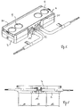
- FIG. 1 an exploded view of a first embodiment of a facade lamp according to the invention is shown.
- the facade lamp has a housing which consists of a housing lower part 3 and a housing upper part 4.
- the lower housing part is divided into three sections A1, A2, A3.
- two LED clusters 1 are arranged in the lateral sections A1 and A3.
- An LED cluster 1 is formed from at least two light-emitting diodes.
- three LEDs per LED cluster 1 are used, namely with the colors red, green and blue; It is also possible to use two preferably three white LEDs per LED cluster 1.
- an optical system 2 Seen in the light exit direction in front of each LED cluster 1, an optical system 2 is arranged.
- This optic 2 generates an elliptical light distribution on the illuminated surface.
- the four LED clusters 1, together with the total of four optics 2 produce a light distribution which illuminates a broad strip on the surface to be illuminated, that is, as a rule, on a facade or wall.
- a narrow construction of the façade luminaire is ensured by the fact that the LED clusters are arranged side by side, in particular substantially along a straight line. This straight line runs parallel to the longitudinal extension of the elliptical light distribution, preferably centrally through the luminaire.
- the LEDs of the LED cluster 1 are mounted on boards 5 or soldered. As in FIG. 2 it can be seen that the boards 5 are located with their backs on a contact surface 8 of the base 7 of the heat sink.
- the lower housing part 3 at the same time designed as a heat sink.
- the lower housing part 3 in the region of the lateral sections A1 and A3 on cooling fins 6, which are integrally formed on the base 7.
- the cooling fins 6 extend in the longitudinal direction of the lower housing part 3.
- the lower housing part is surrounded by substantially straight and smooth outer walls. This shape design is possible because the lower housing part 3 is designed as an aluminum die cast part.
- the frontal outer walls can be omitted to allow for improved air circulation.
- the height of the cooling fins 6 with base 7 corresponds approximately to the depth of the receiving space 15.
- the middle section A2 (not shown) operating devices, such as LED drivers or control units, such as DMX controllers and (not shown) electrical terminals are housed.
- the electrical supply is via standard cable glands through which a (not shown) cable can be passed and the housing and cable seal against each other.
- the façade luminaire according to the invention is supplied via a low-voltage power supply with 24 V or 48 V, the supply unit, ie the LED driver is usually placed outside of the lamp and in the space provided usually only the control unit together with (not shown) terminals is arranged.
- the receiving space 15 and the two lateral sections A1 and A3 are closed to the top with a circumferential ridge 10.
- This web 10 receives a circumferential seal 11, wherein the profile of this seal - as in FIG. 2 seen - the contour of the web 11 is adjusted. Also in FIG. 2 it can be seen that the seal 11 engages in a circumferential groove 16 of the housing upper part 4.
- the upper housing part 4 is formed from an opaque part, which is preferably made of polycarbonate and in the present embodiment of four circularly designed translucent, crystal clear cover elements 9, which are preferably made of polymethyl methacrylate.
- the production of the upper housing part 4 can be done by means of 2K injection molding.
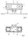
- FIG. 3 is a front view of the embodiment according to FIG. 1 shown.
- the upper housing part 4 engages over the lower housing part 3 with tab-like side walls 14, wherein recesses 17 are provided in the side walls, which cooperate with snap lugs 12 and form the snap lock between the upper housing part 4 and lower housing part 3.
- a total of nine snap tabs 12 are distributed over the tab-like side wall on one side of the housing base 3.
- FIGS. 5 to 8 A second embodiment of a facade light according to the invention is in the FIGS. 5 to 8 represented, wherein like elements are provided with the same reference numerals.
- this second exemplary embodiment is the same as the example of FIGS. 1 to 4 .
- the means for influencing the light output are identical here, which is why below the differences are to be explained in the first place.
- An essential difference in this second embodiment consists in the fact that the removal of the heat occurring during the LED operation takes place primarily with the aid of air slots 20, which are formed in the vicinity of the LED cluster 1 in the housing.
- these louvers 20 are formed on the inner circumference of the wall of the lower housing part 3, which is achieved by a corresponding - at least partially - double-walled design of the housing wall.
- the upper housing part 4 then no longer completely overlaps the housing lower part 3, but instead is configured such that the side wall 14 engages with the tabs in the air slot (s) 20 and interacts with snap-action lugs located here.
- the lower housing part 3 Only in the central region A2 in the region of the cable glands 13, the lower housing part 3 is not double-walled, so that here a tab engages over the lower housing part 3.
- the width of the louvers 20 is dimensioned such that, despite engagement of the side wall 14, sufficient free space remains, which allows a passage of air and, accordingly, an effective dissipation of heat.
- the located on the lower housing part 3 web 10 for receiving the seal 11 is slightly offset in this case formed on the inside of the louvers 20, so that still the required reliable sealing of the lamp is achieved.
- louvers 20 are respectively formed on the two longitudinal sides of the housing in the region of the lateral portions A1 and A3 for receiving the LED cluster 1, through which a very effective dissipation of the heat is achieved. It has been found that the effect of these louvers 20 is even so effective that no further measures for cooling would be required. Accordingly, in this embodiment, also on the arranged below the LED cluster 1 cooling fins 6, as in the example of the FIGS. 1 to 4 are provided, are waived. Instead, it is merely provided in this variant that substantially square depressions 21 are formed in these areas on the underside of the housing lower part 3. The preparation of the turn, preferably designed as Aluminium horrgußteil housing lower part 3 is thereby simplified. Of course, it would be conceivable, however, to increase the cooling capacity, even in this second embodiment form additional cooling fins, if this seems reasonable due to the environmental influences.
Landscapes
- Engineering & Computer Science (AREA)
- General Engineering & Computer Science (AREA)
- Power Engineering (AREA)
- Arrangement Of Elements, Cooling, Sealing, Or The Like Of Lighting Devices (AREA)
- Non-Portable Lighting Devices Or Systems Thereof (AREA)
Claims (18)
- Luminaire pour façade avec un logement pour recevoir des moyens d'éclairage, des dispositifs opérationnels et des bornes de connexion, à diodes électroluminescentes comme moyens d'éclairage et éléments optiques pour la distribution de la lumière émise par les diodes électroluminescentes, caractérisé en ce qu'au moins deux diodes électroluminescentes sont associées pour former des clusters de DEL (1), c'est-à-dire qu'un élément optique (2) est attribué à chaque cluster de DEL (1), dans lequel la lumière émise par les diodes électroluminescentes des clusters de DEL (1) passe à travers l'élément optique (2) et dans lequel l'élément optique (2) est conçu de manière à ce qu'il génère une distribution elliptique de la lumière, en ce que le logement est subdivisé en au moins deux sections (A1, A2), dans lequel se trouve une chambre pour les dispositifs opérationnels dans une première section (A2) et dans lequel est disposé au moins un cluster de DEL (1) dans une deuxième section latérale (A1, A3), en ce que chaque cluster de DEL (1) est accouplé à des moyens pour dissiper la chaleur générée durant le fonctionnement des diodes électroluminescentes, et en ce que les clusters de DEL (1) sont disposés l'un à côté de l'autre, essentiellement le long d'une droite, dans lequel la droite est parallèle à l'extension longitudinale de la distribution elliptique de la lumière.
- Luminaire pour façade selon la revendication 1, caractérisé en ce que des interstices (20) sont formés dans le logement pour dissiper la chaleur.
- Luminaire pour façade selon la revendication 2, caractérisé en ce que les interstices (20) sont formés entre une zone de réception pour les clusters de DEL (1) et une paroi de logement périphérique.
- Luminaire pour façade selon l'une quelconque des revendications précédentes, caractérisé en ce que le logement est subdivisé en trois sections (A1, A2, A3), dans lequel une chambre se trouve dans la section centrale (A2) pour des dispositifs opérationnels et/ou des bornes de connexion et en ce que, dans les sections latérales (A1, A3), est disposé, respectivement, au moins un cluster de DEL (1).
- Luminaire pour façade selon la revendication 4, caractérisé en ce que deux clusters de DEL (1) sont disposés, respectivement, dans les sections latérales (A1, A3).
- Luminaire de façade selon l'une quelconque des revendications précédentes, caractérisé en ce que dans la section latérale ou les sections latérales (A1, A3) des éléments de refroidissement sont attribués aux clusters de DEL (1).
- Luminaire de façade selon la revendication 6, caractérisé en ce que les clusters de DEL (1) consistent en au moins deux diodes électroluminescentes, en ce que les diodes électroluminescentes sont disposées sur un premier côté de cartes de circuit imprimé (5), en particulier des cartes de circuit imprimé à noyau métallique, et en ce que les cartes de circuit imprimé (5) sont raccordées en conduction thermique du côté opposé du premier côté avec l'élément de refroidissement.
- Luminaire de façade selon l'une des revendications 4 ou 5 et selon l'une des revendications 6 ou 7, caractérisé en ce que l'élément de refroidissement est intégralement formé, en ce qu'il est subdivisé en trois sections ici et en ce que dans la première section il est raccordé en conduction thermique aux cartes de circuits imprimés disposées dans la première section latérale du logement, et en ce que dans la deuxième section il est à cheval sur la chambre pour les dispositifs opérationnels, et en ce que dans la deuxième section latérale il est raccordé en conduction thermique aux cartes de circuit imprimé disposées dans la troisième section du logement.
- Luminaire de façade selon l'une des revendications de 6 à 8, caractérisé en ce que l'élément de refroidissement forme des ailettes (6) dans la zone des sections latérales, en ce que les ailettes de refroidissement (6) montent depuis un côté d'une base (7), en ce que la hauteur des ailettes de refroidissement (6) correspond approximativement à la profondeur de la chambre (15) prévue pour recevoir les dispositifs opérationnels, et en ce que le côté de la base (7) qui est à l'opposé du côté mentionné sert de face de contact (8) entre la carte de circuit imprimé (5) et l'élément de refroidissement.
- Luminaire de façade selon l'une des revendications de 6 à 9, caractérisé en ce que l'élément de refroidissement forme dans la section centrale (A2) une chambre, fermée de tous les côtés à l'exception du dessus, pour des dispositifs opérationnels et/ou des bornes de connexion.
- Luminaire de façade selon l'une quelconque des revendications précédentes, caractérisé en ce que le logement consiste en une partie de base de logement (3) et en une partie supérieure de logement (4), et en ce que de préférence la partie de base de logement (4) est conçue comme un élément de refroidissement.
- Luminaire de façade selon la revendication 11, caractérisé en ce que la partie de base de logement (4) est réalisée en aluminium moulé sous pression.
- Luminaire de façade selon la revendication 11 ou 12, caractérisé en ce que la partie supérieure de logement (4) est réalisée dans un matériau synthétique, dans laquelle des zones étanches à la lumière sont réalisées en polycarbonate et des zones perméables à la lumière sont réalisées comme des éléments de couverture (9) en poly(méthacrylate de méthyle).
- Luminaire de façade selon la revendication 13, caractérisé en ce que la partie supérieure de logement (4) est fabriquée moyennant un moulage par injection de deux composants.
- Luminaire de façade selon l'une des revendications de 11 à 14, caractérisé en ce que la partie de base de logement (3) présente une barre périphérique (10), et en ce qu'un joint périphérique (11) est disposé sur la barre périphérique (10).
- Luminaire de façade selon l'une des revendications de 11 à 15, caractérisé en ce que la partie supérieure de logement (4) est attachée à la partie de base de logement (3) par l'intermédiaire d'un raccordement à encliquetage de manière à ce que la partie supérieure de logement (4) soit pressée contre le joint (11).
- Luminaire de façade selon l'une quelconque des revendications précédentes, caractérisé en ce que les diodes électroluminescentes et une unité de commande associée fonctionnent au moyen d'un système à basse tension.
- Luminaire de façade selon la revendication 16, caractérisé en ce que le raccordement à encliquetage est réalisée par la partie supérieure de logement (4) chevauchant latéralement la partie de base de logement (3) ou s'engageant dans des passages d'air (20) formés sur la partie de base de logement (3), et en ce que les renfoncements (17) sont réalisés dans les zones latérales de la partie supérieure de logement (4) à l'intérieur duquel des nez à encliquetage (12) s'engagent lorsque la partie de base de logement (3) est fermée avec la partie supérieure de logement (4), dans laquelle les nez à encliquetage (12) sont intégralement moulés dans la partie de base de logement (3).
Applications Claiming Priority (2)
| Application Number | Priority Date | Filing Date | Title |
|---|---|---|---|
| ATGM101/2011U AT12903U1 (de) | 2011-02-18 | 2011-02-18 | Fassadenleuchte mit leuchtdioden |
| PCT/EP2012/052766 WO2012110633A1 (fr) | 2011-02-18 | 2012-02-17 | Luminaire pour façade à diodes électroluminescentes |
Publications (2)
| Publication Number | Publication Date |
|---|---|
| EP2676070A1 EP2676070A1 (fr) | 2013-12-25 |
| EP2676070B1 true EP2676070B1 (fr) | 2016-02-17 |
Family
ID=46671963
Family Applications (1)
| Application Number | Title | Priority Date | Filing Date |
|---|---|---|---|
| EP12705839.4A Active EP2676070B1 (fr) | 2011-02-18 | 2012-02-17 | Luminaire pour façade à diodes électroluminescentes |
Country Status (5)
| Country | Link |
|---|---|
| US (1) | US9464766B2 (fr) |
| EP (1) | EP2676070B1 (fr) |
| CN (1) | CN103403443B (fr) |
| AT (1) | AT12903U1 (fr) |
| WO (1) | WO2012110633A1 (fr) |
Families Citing this family (6)
| Publication number | Priority date | Publication date | Assignee | Title |
|---|---|---|---|---|
| DE202012104404U1 (de) * | 2012-11-15 | 2014-02-17 | Zumtobel Lighting Gmbh | Schaltung zum Betreiben einer Lichtquelle mit Temperaturüberwachung |
| DE202013100577U1 (de) | 2013-02-08 | 2014-05-09 | Zumtobel Lighting Gmbh | Fassadenleuchte |
| USD736988S1 (en) * | 2013-12-30 | 2015-08-18 | Hangzhou Hpwinner Opto Corporation | LED lens |
| USD736992S1 (en) * | 2014-06-26 | 2015-08-18 | Hangzhou Hpwinner Opto Corporation | LED lens |
| US11346536B2 (en) * | 2018-06-28 | 2022-05-31 | Signify Holding B.V. | Kit of parts comprising a cable gland, a wire transport element and a housing, system made of such a kit, and method for functionally connecting the system |
| CN210979614U (zh) * | 2019-09-23 | 2020-07-10 | 漳州立达信光电子科技有限公司 | 橱柜灯 |
Family Cites Families (22)
| Publication number | Priority date | Publication date | Assignee | Title |
|---|---|---|---|---|
| ITTO20030673A1 (it) | 2003-09-04 | 2005-03-05 | Space Cannon Vh S P A | Barra di luce a led. |
| US7165863B1 (en) * | 2004-09-23 | 2007-01-23 | Pricilla G. Thomas | Illumination system |
| US8113687B2 (en) * | 2006-06-29 | 2012-02-14 | Cree, Inc. | Modular LED lighting fixture |
| US7686469B2 (en) * | 2006-09-30 | 2010-03-30 | Ruud Lighting, Inc. | LED lighting fixture |
| US7771099B2 (en) * | 2007-04-30 | 2010-08-10 | Hewlett-Packard Development Company, L.P. | Electronic device with backlit display |
| CN201133634Y (zh) * | 2007-06-07 | 2008-10-15 | 浙江名创光电科技有限公司 | 大功率led灯 |
| US7434959B1 (en) * | 2007-08-14 | 2008-10-14 | Augux Co., Ltd. | LED lamp device |
| CN201074792Y (zh) * | 2007-08-16 | 2008-06-18 | 陈照军 | 散热型led灯具 |
| WO2009026736A1 (fr) * | 2007-08-24 | 2009-03-05 | He Shan Lide Electronic Enterprise Company Ltd. | Réverbère à del |
| US7588355B1 (en) * | 2008-03-19 | 2009-09-15 | Fu Zhun Precision Industry (Shen Zhen) Co., Ltd. | LED lamp assembly |
| CN101545594B (zh) * | 2008-03-26 | 2010-09-29 | 富准精密工业(深圳)有限公司 | 发光二极管路灯 |
| CN101551074A (zh) * | 2008-04-03 | 2009-10-07 | 富准精密工业(深圳)有限公司 | 发光二极管路灯 |
| US7637637B2 (en) * | 2008-04-16 | 2009-12-29 | Fu Zhun Precision Industry (Shen Zhen) Co., Ltd. | Outdoor LED lamp assembly |
| AU2009291403A1 (en) * | 2008-09-15 | 2010-03-18 | Led Roadway Lighting Ltd. | Light emitting diode (LED) roadway lighting fixture |
| DE102009016256A1 (de) * | 2009-04-03 | 2010-10-14 | Vishay Electronic Gmbh | Außenraum-Beleuchtungseinheit |
| CN101871583A (zh) * | 2009-04-23 | 2010-10-27 | 富准精密工业(深圳)有限公司 | 发光二极管灯具 |
| US8066392B2 (en) * | 2009-06-02 | 2011-11-29 | Ceramate Technical Co., Ltd. | Multi-function replaceable modular LED lamp |
| WO2010143204A2 (fr) * | 2009-06-10 | 2010-12-16 | Shirish Devidas Deshpande | Appareils d'éclairage à semi-conducteurs adaptables, longue durée, thermiquement efficaces et sans danger pour l'environnement |
| EP3045798B1 (fr) * | 2009-07-28 | 2017-10-04 | LG Innotek Co., Ltd. | Dispositif d'éclairage |
| CN101655204B (zh) * | 2009-09-16 | 2012-06-27 | 山东魏仕照明科技有限公司 | 一种led洗墙灯 |
| CN201593732U (zh) * | 2010-01-29 | 2010-09-29 | 郑州天阳新能源科技有限公司 | 大功率led路灯 |
| CN201615376U (zh) * | 2010-03-03 | 2010-10-27 | 河北勤道光伏科技有限公司 | 一种大功率led组合灯具 |
-
2011
- 2011-02-18 AT ATGM101/2011U patent/AT12903U1/de not_active IP Right Cessation
-
2012
- 2012-02-17 EP EP12705839.4A patent/EP2676070B1/fr active Active
- 2012-02-17 US US13/985,225 patent/US9464766B2/en not_active Expired - Fee Related
- 2012-02-17 WO PCT/EP2012/052766 patent/WO2012110633A1/fr active Application Filing
- 2012-02-17 CN CN201280007679.6A patent/CN103403443B/zh not_active Expired - Fee Related
Also Published As
| Publication number | Publication date |
|---|---|
| US9464766B2 (en) | 2016-10-11 |
| CN103403443A (zh) | 2013-11-20 |
| WO2012110633A1 (fr) | 2012-08-23 |
| US20140185289A1 (en) | 2014-07-03 |
| CN103403443B (zh) | 2016-11-09 |
| EP2676070A1 (fr) | 2013-12-25 |
| AT12903U1 (de) | 2013-01-15 |
Similar Documents
| Publication | Publication Date | Title |
|---|---|---|
| EP2676070B1 (fr) | Luminaire pour façade à diodes électroluminescentes | |
| WO2010092106A1 (fr) | Module d'éclairage et procédé de fabrication d'un module d'éclairage | |
| EP3076068B1 (fr) | Luminaire lineaire et profile support pour luminaire lineaire | |
| DE202008012317U1 (de) | Beleuchtungsvorrichtung aus streifenförmigen Leuchtdiodenlampen | |
| DE19956799A1 (de) | Leuchte nach Art einer Signal- und/oder Orientierungsleuchte | |
| DE102008004238A1 (de) | Leuchtsystem | |
| EP1649209B1 (fr) | Lampe utilisee a des fins d'eclairage | |
| AT17505U1 (de) | Leuchte mit geschützt gelagerten Leuchtmitteln | |
| WO2002052191A1 (fr) | Element fenetre | |
| WO2004042271A2 (fr) | Guide d'onde optique pour systemes d'eclairage de vehicules, de preference de vehicules automobiles | |
| AT17464U1 (de) | Wannenförmiges Leuchtengehäuse | |
| EP1762433A2 (fr) | Ensemble de feux arrière, en particuliers pour véhicules utilitaires | |
| DE202008004442U1 (de) | Leuchtenprofil | |
| EP2042802B1 (fr) | Lampe dotée d'un profilé de recouvrement | |
| DE102015103138A1 (de) | LED-Leuchten-Bausatz | |
| DE102009009520A1 (de) | Steckmodul für ein modular aufgebautes Leuchtmittel, Leuchtmodul für das Leuchtmittel sowie modular aufgebautes Leuchtmittel | |
| EP3366986B1 (fr) | Capot du luminaire et luminaire | |
| DE202012103474U1 (de) | LED-Leuchte | |
| EP3133341A1 (fr) | Dispositif d'eclairage | |
| EP3969807B1 (fr) | Appareil d'éclairage comportant des canaux à air de refroidissement | |
| EP2484961A1 (fr) | Recouvrement pour un boîtier de lampes | |
| DE102019210025B4 (de) | Lichteinsatz, Verfahren zu dessen Herstellung und Beleuchtungssystem | |
| EP2910843B1 (fr) | Lampe | |
| DE29920334U1 (de) | Leuchteinrichtung | |
| EP1918635B1 (fr) | Lampe d'ambiance |
Legal Events
| Date | Code | Title | Description |
|---|---|---|---|
| PUAI | Public reference made under article 153(3) epc to a published international application that has entered the european phase |
Free format text: ORIGINAL CODE: 0009012 |
|
| 17P | Request for examination filed |
Effective date: 20130814 |
|
| AK | Designated contracting states |
Kind code of ref document: A1 Designated state(s): AL AT BE BG CH CY CZ DE DK EE ES FI FR GB GR HR HU IE IS IT LI LT LU LV MC MK MT NL NO PL PT RO RS SE SI SK SM TR |
|
| DAX | Request for extension of the european patent (deleted) | ||
| 17Q | First examination report despatched |
Effective date: 20150310 |
|
| GRAP | Despatch of communication of intention to grant a patent |
Free format text: ORIGINAL CODE: EPIDOSNIGR1 |
|
| RIC1 | Information provided on ipc code assigned before grant |
Ipc: F21V 17/16 20060101ALN20150831BHEP Ipc: F21V 15/01 20060101ALI20150831BHEP Ipc: F21V 23/02 20060101AFI20150831BHEP Ipc: F21V 29/507 20150101ALI20150831BHEP Ipc: F21Y 101/02 20060101ALN20150831BHEP Ipc: F21W 131/107 20060101ALN20150831BHEP Ipc: F21V 29/76 20150101ALI20150831BHEP |
|
| INTG | Intention to grant announced |
Effective date: 20151007 |
|
| GRAS | Grant fee paid |
Free format text: ORIGINAL CODE: EPIDOSNIGR3 |
|
| REG | Reference to a national code |
Ref country code: DE Ref legal event code: R079 Ref document number: 502012006012 Country of ref document: DE Free format text: PREVIOUS MAIN CLASS: F21V0015010000 Ipc: F21V0023020000 |
|
| GRAA | (expected) grant |
Free format text: ORIGINAL CODE: 0009210 |
|
| RIC1 | Information provided on ipc code assigned before grant |
Ipc: F21V 23/02 20060101AFI20151216BHEP Ipc: F21V 29/507 20150101ALI20151216BHEP Ipc: F21V 15/01 20060101ALI20151216BHEP Ipc: F21V 17/16 20060101ALN20151216BHEP Ipc: F21W 131/107 20060101ALN20151216BHEP Ipc: F21V 29/76 20150101ALI20151216BHEP |
|
| AK | Designated contracting states |
Kind code of ref document: B1 Designated state(s): AL AT BE BG CH CY CZ DE DK EE ES FI FR GB GR HR HU IE IS IT LI LT LU LV MC MK MT NL NO PL PT RO RS SE SI SK SM TR |
|
| REG | Reference to a national code |
Ref country code: GB Ref legal event code: FG4D Free format text: NOT ENGLISH |
|
| REG | Reference to a national code |
Ref country code: CH Ref legal event code: EP Ref country code: FR Ref legal event code: PLFP Year of fee payment: 5 |
|
| REG | Reference to a national code |
Ref country code: IE Ref legal event code: FG4D Free format text: LANGUAGE OF EP DOCUMENT: GERMAN |
|
| REG | Reference to a national code |
Ref country code: AT Ref legal event code: REF Ref document number: 775823 Country of ref document: AT Kind code of ref document: T Effective date: 20160315 |
|
| REG | Reference to a national code |
Ref country code: DE Ref legal event code: R096 Ref document number: 502012006012 Country of ref document: DE |
|
| REG | Reference to a national code |
Ref country code: CH Ref legal event code: NV Representative=s name: WEINMANN ZIMMERLI, CH |
|
| REG | Reference to a national code |
Ref country code: NL Ref legal event code: MP Effective date: 20160217 |
|
| REG | Reference to a national code |
Ref country code: LT Ref legal event code: MG4D |
|
| PG25 | Lapsed in a contracting state [announced via postgrant information from national office to epo] |
Ref country code: HR Free format text: LAPSE BECAUSE OF FAILURE TO SUBMIT A TRANSLATION OF THE DESCRIPTION OR TO PAY THE FEE WITHIN THE PRESCRIBED TIME-LIMIT Effective date: 20160217 Ref country code: FI Free format text: LAPSE BECAUSE OF FAILURE TO SUBMIT A TRANSLATION OF THE DESCRIPTION OR TO PAY THE FEE WITHIN THE PRESCRIBED TIME-LIMIT Effective date: 20160217 Ref country code: ES Free format text: LAPSE BECAUSE OF FAILURE TO SUBMIT A TRANSLATION OF THE DESCRIPTION OR TO PAY THE FEE WITHIN THE PRESCRIBED TIME-LIMIT Effective date: 20160217 Ref country code: IT Free format text: LAPSE BECAUSE OF FAILURE TO SUBMIT A TRANSLATION OF THE DESCRIPTION OR TO PAY THE FEE WITHIN THE PRESCRIBED TIME-LIMIT Effective date: 20160217 Ref country code: NO Free format text: LAPSE BECAUSE OF FAILURE TO SUBMIT A TRANSLATION OF THE DESCRIPTION OR TO PAY THE FEE WITHIN THE PRESCRIBED TIME-LIMIT Effective date: 20160517 Ref country code: GR Free format text: LAPSE BECAUSE OF FAILURE TO SUBMIT A TRANSLATION OF THE DESCRIPTION OR TO PAY THE FEE WITHIN THE PRESCRIBED TIME-LIMIT Effective date: 20160518 |
|
| PG25 | Lapsed in a contracting state [announced via postgrant information from national office to epo] |
Ref country code: SE Free format text: LAPSE BECAUSE OF FAILURE TO SUBMIT A TRANSLATION OF THE DESCRIPTION OR TO PAY THE FEE WITHIN THE PRESCRIBED TIME-LIMIT Effective date: 20160217 Ref country code: PT Free format text: LAPSE BECAUSE OF FAILURE TO SUBMIT A TRANSLATION OF THE DESCRIPTION OR TO PAY THE FEE WITHIN THE PRESCRIBED TIME-LIMIT Effective date: 20160617 Ref country code: BE Free format text: LAPSE BECAUSE OF NON-PAYMENT OF DUE FEES Effective date: 20160229 Ref country code: LT Free format text: LAPSE BECAUSE OF FAILURE TO SUBMIT A TRANSLATION OF THE DESCRIPTION OR TO PAY THE FEE WITHIN THE PRESCRIBED TIME-LIMIT Effective date: 20160217 Ref country code: PL Free format text: LAPSE BECAUSE OF FAILURE TO SUBMIT A TRANSLATION OF THE DESCRIPTION OR TO PAY THE FEE WITHIN THE PRESCRIBED TIME-LIMIT Effective date: 20160217 Ref country code: RS Free format text: LAPSE BECAUSE OF FAILURE TO SUBMIT A TRANSLATION OF THE DESCRIPTION OR TO PAY THE FEE WITHIN THE PRESCRIBED TIME-LIMIT Effective date: 20160217 Ref country code: LV Free format text: LAPSE BECAUSE OF FAILURE TO SUBMIT A TRANSLATION OF THE DESCRIPTION OR TO PAY THE FEE WITHIN THE PRESCRIBED TIME-LIMIT Effective date: 20160217 Ref country code: NL Free format text: LAPSE BECAUSE OF FAILURE TO SUBMIT A TRANSLATION OF THE DESCRIPTION OR TO PAY THE FEE WITHIN THE PRESCRIBED TIME-LIMIT Effective date: 20160217 |
|
| PG25 | Lapsed in a contracting state [announced via postgrant information from national office to epo] |
Ref country code: EE Free format text: LAPSE BECAUSE OF FAILURE TO SUBMIT A TRANSLATION OF THE DESCRIPTION OR TO PAY THE FEE WITHIN THE PRESCRIBED TIME-LIMIT Effective date: 20160217 Ref country code: DK Free format text: LAPSE BECAUSE OF FAILURE TO SUBMIT A TRANSLATION OF THE DESCRIPTION OR TO PAY THE FEE WITHIN THE PRESCRIBED TIME-LIMIT Effective date: 20160217 |
|
| REG | Reference to a national code |
Ref country code: DE Ref legal event code: R097 Ref document number: 502012006012 Country of ref document: DE |
|
| PG25 | Lapsed in a contracting state [announced via postgrant information from national office to epo] |
Ref country code: SK Free format text: LAPSE BECAUSE OF FAILURE TO SUBMIT A TRANSLATION OF THE DESCRIPTION OR TO PAY THE FEE WITHIN THE PRESCRIBED TIME-LIMIT Effective date: 20160217 Ref country code: RO Free format text: LAPSE BECAUSE OF FAILURE TO SUBMIT A TRANSLATION OF THE DESCRIPTION OR TO PAY THE FEE WITHIN THE PRESCRIBED TIME-LIMIT Effective date: 20160217 Ref country code: CZ Free format text: LAPSE BECAUSE OF FAILURE TO SUBMIT A TRANSLATION OF THE DESCRIPTION OR TO PAY THE FEE WITHIN THE PRESCRIBED TIME-LIMIT Effective date: 20160217 Ref country code: SM Free format text: LAPSE BECAUSE OF FAILURE TO SUBMIT A TRANSLATION OF THE DESCRIPTION OR TO PAY THE FEE WITHIN THE PRESCRIBED TIME-LIMIT Effective date: 20160217 |
|
| REG | Reference to a national code |
Ref country code: IE Ref legal event code: MM4A |
|
| PLBE | No opposition filed within time limit |
Free format text: ORIGINAL CODE: 0009261 |
|
| STAA | Information on the status of an ep patent application or granted ep patent |
Free format text: STATUS: NO OPPOSITION FILED WITHIN TIME LIMIT |
|
| 26N | No opposition filed |
Effective date: 20161118 |
|
| PG25 | Lapsed in a contracting state [announced via postgrant information from national office to epo] |
Ref country code: IE Free format text: LAPSE BECAUSE OF NON-PAYMENT OF DUE FEES Effective date: 20160217 |
|
| REG | Reference to a national code |
Ref country code: FR Ref legal event code: PLFP Year of fee payment: 6 |
|
| PG25 | Lapsed in a contracting state [announced via postgrant information from national office to epo] |
Ref country code: BG Free format text: LAPSE BECAUSE OF FAILURE TO SUBMIT A TRANSLATION OF THE DESCRIPTION OR TO PAY THE FEE WITHIN THE PRESCRIBED TIME-LIMIT Effective date: 20160517 Ref country code: SI Free format text: LAPSE BECAUSE OF FAILURE TO SUBMIT A TRANSLATION OF THE DESCRIPTION OR TO PAY THE FEE WITHIN THE PRESCRIBED TIME-LIMIT Effective date: 20160217 |
|
| PGFP | Annual fee paid to national office [announced via postgrant information from national office to epo] |
Ref country code: CH Payment date: 20170224 Year of fee payment: 6 |
|
| PGFP | Annual fee paid to national office [announced via postgrant information from national office to epo] |
Ref country code: AT Payment date: 20170227 Year of fee payment: 6 |
|
| REG | Reference to a national code |
Ref country code: CH Ref legal event code: PK Free format text: DAS PRIORITAETSAKTENZEICHEN WURDE BERICHTIGT: AT 1012011 U / 18.02.2011 |
|
| PG25 | Lapsed in a contracting state [announced via postgrant information from national office to epo] |
Ref country code: MT Free format text: LAPSE BECAUSE OF FAILURE TO SUBMIT A TRANSLATION OF THE DESCRIPTION OR TO PAY THE FEE WITHIN THE PRESCRIBED TIME-LIMIT Effective date: 20160217 |
|
| PG25 | Lapsed in a contracting state [announced via postgrant information from national office to epo] |
Ref country code: MC Free format text: LAPSE BECAUSE OF FAILURE TO SUBMIT A TRANSLATION OF THE DESCRIPTION OR TO PAY THE FEE WITHIN THE PRESCRIBED TIME-LIMIT Effective date: 20160217 |
|
| REG | Reference to a national code |
Ref country code: FR Ref legal event code: PLFP Year of fee payment: 7 |
|
| PG25 | Lapsed in a contracting state [announced via postgrant information from national office to epo] |
Ref country code: CY Free format text: LAPSE BECAUSE OF FAILURE TO SUBMIT A TRANSLATION OF THE DESCRIPTION OR TO PAY THE FEE WITHIN THE PRESCRIBED TIME-LIMIT Effective date: 20160217 Ref country code: HU Free format text: LAPSE BECAUSE OF FAILURE TO SUBMIT A TRANSLATION OF THE DESCRIPTION OR TO PAY THE FEE WITHIN THE PRESCRIBED TIME-LIMIT; INVALID AB INITIO Effective date: 20120217 |
|
| PG25 | Lapsed in a contracting state [announced via postgrant information from national office to epo] |
Ref country code: MK Free format text: LAPSE BECAUSE OF FAILURE TO SUBMIT A TRANSLATION OF THE DESCRIPTION OR TO PAY THE FEE WITHIN THE PRESCRIBED TIME-LIMIT Effective date: 20160217 Ref country code: TR Free format text: LAPSE BECAUSE OF FAILURE TO SUBMIT A TRANSLATION OF THE DESCRIPTION OR TO PAY THE FEE WITHIN THE PRESCRIBED TIME-LIMIT Effective date: 20160217 Ref country code: LU Free format text: LAPSE BECAUSE OF NON-PAYMENT OF DUE FEES Effective date: 20160217 Ref country code: IS Free format text: LAPSE BECAUSE OF FAILURE TO SUBMIT A TRANSLATION OF THE DESCRIPTION OR TO PAY THE FEE WITHIN THE PRESCRIBED TIME-LIMIT Effective date: 20160217 |
|
| REG | Reference to a national code |
Ref country code: CH Ref legal event code: PL |
|
| REG | Reference to a national code |
Ref country code: AT Ref legal event code: MM01 Ref document number: 775823 Country of ref document: AT Kind code of ref document: T Effective date: 20180217 |
|
| PG25 | Lapsed in a contracting state [announced via postgrant information from national office to epo] |
Ref country code: AL Free format text: LAPSE BECAUSE OF FAILURE TO SUBMIT A TRANSLATION OF THE DESCRIPTION OR TO PAY THE FEE WITHIN THE PRESCRIBED TIME-LIMIT Effective date: 20160217 |
|
| PG25 | Lapsed in a contracting state [announced via postgrant information from national office to epo] |
Ref country code: CH Free format text: LAPSE BECAUSE OF NON-PAYMENT OF DUE FEES Effective date: 20180228 Ref country code: LI Free format text: LAPSE BECAUSE OF NON-PAYMENT OF DUE FEES Effective date: 20180228 Ref country code: AT Free format text: LAPSE BECAUSE OF NON-PAYMENT OF DUE FEES Effective date: 20180217 |
|
| REG | Reference to a national code |
Ref country code: DE Ref legal event code: R084 Ref document number: 502012006012 Country of ref document: DE |
|
| PGFP | Annual fee paid to national office [announced via postgrant information from national office to epo] |
Ref country code: FR Payment date: 20190226 Year of fee payment: 8 |
|
| PG25 | Lapsed in a contracting state [announced via postgrant information from national office to epo] |
Ref country code: FR Free format text: LAPSE BECAUSE OF NON-PAYMENT OF DUE FEES Effective date: 20200229 |
|
| PGFP | Annual fee paid to national office [announced via postgrant information from national office to epo] |
Ref country code: GB Payment date: 20220222 Year of fee payment: 11 |
|
| PGFP | Annual fee paid to national office [announced via postgrant information from national office to epo] |
Ref country code: DE Payment date: 20230227 Year of fee payment: 12 |
|
| P01 | Opt-out of the competence of the unified patent court (upc) registered |
Effective date: 20230530 |
|
| GBPC | Gb: european patent ceased through non-payment of renewal fee |
Effective date: 20230217 |
|
| PG25 | Lapsed in a contracting state [announced via postgrant information from national office to epo] |
Ref country code: GB Free format text: LAPSE BECAUSE OF NON-PAYMENT OF DUE FEES Effective date: 20230217 |
|
| PG25 | Lapsed in a contracting state [announced via postgrant information from national office to epo] |
Ref country code: GB Free format text: LAPSE BECAUSE OF NON-PAYMENT OF DUE FEES Effective date: 20230217 |