EP2671824B1 - Bereitstellungseinrichtung und- verfahren für Holzbrennstoffpellets - Google Patents
Bereitstellungseinrichtung und- verfahren für Holzbrennstoffpellets Download PDFInfo
- Publication number
- EP2671824B1 EP2671824B1 EP13169529.8A EP13169529A EP2671824B1 EP 2671824 B1 EP2671824 B1 EP 2671824B1 EP 13169529 A EP13169529 A EP 13169529A EP 2671824 B1 EP2671824 B1 EP 2671824B1
- Authority
- EP
- European Patent Office
- Prior art keywords
- conveying
- fuel pellets
- pellet
- actuator
- wood fuel
- Prior art date
- Legal status (The legal status is an assumption and is not a legal conclusion. Google has not performed a legal analysis and makes no representation as to the accuracy of the status listed.)
- Not-in-force
Links
- 239000008188 pellet Substances 0.000 title claims description 128
- 239000002023 wood Substances 0.000 title claims description 60
- 239000000446 fuel Substances 0.000 title claims description 52
- 238000000034 method Methods 0.000 title claims description 10
- 230000000630 rising effect Effects 0.000 claims description 4
- 238000010073 coating (rubber) Methods 0.000 claims description 2
- 239000011248 coating agent Substances 0.000 claims description 2
- 238000000576 coating method Methods 0.000 claims description 2
- 230000001105 regulatory effect Effects 0.000 claims description 2
- 230000001960 triggered effect Effects 0.000 claims description 2
- 230000005284 excitation Effects 0.000 description 11
- 238000002485 combustion reaction Methods 0.000 description 10
- 238000003860 storage Methods 0.000 description 10
- 230000033001 locomotion Effects 0.000 description 9
- 230000010355 oscillation Effects 0.000 description 9
- 238000011161 development Methods 0.000 description 4
- 230000018109 developmental process Effects 0.000 description 4
- 230000004888 barrier function Effects 0.000 description 2
- 230000008878 coupling Effects 0.000 description 2
- 238000010168 coupling process Methods 0.000 description 2
- 238000005859 coupling reaction Methods 0.000 description 2
- 238000013461 design Methods 0.000 description 2
- 238000000926 separation method Methods 0.000 description 2
- 208000033999 Device damage Diseases 0.000 description 1
- 208000027418 Wounds and injury Diseases 0.000 description 1
- 230000000035 biogenic effect Effects 0.000 description 1
- 239000006227 byproduct Substances 0.000 description 1
- 238000004891 communication Methods 0.000 description 1
- 230000006378 damage Effects 0.000 description 1
- 230000001419 dependent effect Effects 0.000 description 1
- 230000002349 favourable effect Effects 0.000 description 1
- 238000010304 firing Methods 0.000 description 1
- 230000005484 gravity Effects 0.000 description 1
- 208000014674 injury Diseases 0.000 description 1
- 238000004519 manufacturing process Methods 0.000 description 1
- 238000012549 training Methods 0.000 description 1
- 238000005303 weighing Methods 0.000 description 1
Images


Classifications
-
- B—PERFORMING OPERATIONS; TRANSPORTING
- B65—CONVEYING; PACKING; STORING; HANDLING THIN OR FILAMENTARY MATERIAL
- B65G—TRANSPORT OR STORAGE DEVICES, e.g. CONVEYORS FOR LOADING OR TIPPING, SHOP CONVEYOR SYSTEMS OR PNEUMATIC TUBE CONVEYORS
- B65G27/00—Jigging conveyors
- B65G27/02—Jigging conveyors comprising helical or spiral channels or conduits for elevation of materials
-
- B—PERFORMING OPERATIONS; TRANSPORTING
- B65—CONVEYING; PACKING; STORING; HANDLING THIN OR FILAMENTARY MATERIAL
- B65G—TRANSPORT OR STORAGE DEVICES, e.g. CONVEYORS FOR LOADING OR TIPPING, SHOP CONVEYOR SYSTEMS OR PNEUMATIC TUBE CONVEYORS
- B65G47/00—Article or material-handling devices associated with conveyors; Methods employing such devices
- B65G47/02—Devices for feeding articles or materials to conveyors
- B65G47/04—Devices for feeding articles or materials to conveyors for feeding articles
- B65G47/12—Devices for feeding articles or materials to conveyors for feeding articles from disorderly-arranged article piles or from loose assemblages of articles
- B65G47/14—Devices for feeding articles or materials to conveyors for feeding articles from disorderly-arranged article piles or from loose assemblages of articles arranging or orientating the articles by mechanical or pneumatic means during feeding
- B65G47/1407—Devices for feeding articles or materials to conveyors for feeding articles from disorderly-arranged article piles or from loose assemblages of articles arranging or orientating the articles by mechanical or pneumatic means during feeding the articles being fed from a container, e.g. a bowl
- B65G47/1442—Devices for feeding articles or materials to conveyors for feeding articles from disorderly-arranged article piles or from loose assemblages of articles arranging or orientating the articles by mechanical or pneumatic means during feeding the articles being fed from a container, e.g. a bowl by means of movement of the bottom or a part of the wall of the container
- B65G47/145—Jigging or reciprocating movement
Definitions
- the invention relates to a supply device for wood fuel pellets according to the preamble of claim 1 and a method for providing wood fuel pellets according to claim 8.
- a supply device is, for example, from US-A-48775284 known.
- Wood fuel pellets are a biogenic fuel made entirely or predominantly from wood or saw-by by-products. These are, for example, according to the European standard EN 14961 standardized, cylindrical compacts with mostly a diameter of five to six millimeters and a length of eight to thirty millimeters. Wood pellets are stored in pellet stores, from where they must be supplied to a combustion device. For this purpose, among other augers are used, which lie in a trough. This pellets can be transported in the direction of the screw conveyor. The disadvantage here is a high power consumption and inaccurate pellet dosing in small power ranges. The result is an increased fuel demand and a dirty combustion control with increased emissions.
- the object of the invention is therefore to overcome the disadvantages of the prior art, and to develop a supply device for wood fuel pellets, which has a low power consumption and allows accurate pellet dosing over a wide power range, so as to reduce the fuel demand and regulate the combustion low emissions to be able to.
- the pellet dosing should be safe and permanently possible, and the provision device should be inexpensive and easy to manufacture and operate.
- a method is to be developed that can meet these requirements.
- a supply device for wood fuel pellets with a pellet storage and a conveying device with a conveying means for conveying wood fuel pellets in a conveying direction wherein the conveying device with an input side with the Pellet storage is in communication and has a directed from the input side in the conveying direction surface with a slope and an actuator, wherein that the conveyor is mounted substantially rotationally fixed and substantially fixed position and is set into vibration by means of the actuator, wherein the vibration is a geodetic vertical vibration component includes.
- the advantage of such a design is that wood pellets can be moved from the input side in the direction of a combustion device or the like through the vertical vibration component.
- a vibration generator has a low power consumption and the vibrations lead to a relatively continuous movement of the wood pellets over a very large power range.
- a very accurate pellet dosing with very low power range is possible.
- the metering can be carried out in particular by an amplitude modulation or by a frequency modulation of the vibration components, which are therefore preferably not constant.
- the vibration-related locomotion of the pellets is also referred to as a microwit. Consequently, the exact dosage leads to a lower fuel consumption and allows a precisely adapted low-emission combustion control.
- the essentially rotationally stable and positionally stable mounting should allow sufficient freedom of movement for the vibration excitation.
- the non-rotatable and fixed position storage is therefore limited to the range of motion outside the vibration amplitudes.
- necessary actuators may, for example, have a circulating unbalance. Such actuators are inexpensive and can be controlled over a wide control range. Exactly the pellet dosage can be made.
- the conveying device is arranged with its input side in the region of the geodetic bottom end of the pellet store. At the opposite end of the conveyor, the conveyor is equipped with an end discharge edge. Wood fuel pellets moving across this unloading edge are then further moved by gravity, either in free fall or on a chute.
- the oscillation comprises a geodetic horizontal vibration component.
- a geodetically horizontal vibration component By means of such a geodetically horizontal vibration component, a on the surface of the conveyor vertically excited wood pellet are transported uphill, in a sense by horizontally moving back the surface during the vertically excited microwavefloating phase and advancing the surface horizontally during the microfug contact phase.
- An exclusively geodetic vertical vibration excitation is very well suited to transport wood fuel pellets downhill. The impulse for a horizontal movement then takes place by means of the microwell impact of the fuel pellets on the rising surface.
- Suitable horizontal vibration components are either linear movements or torsional vibrations. The selection of this horizontal vibration component depends essentially on the conveying direction, e.g. can be linear, straight or spiral.
- the oscillation comprises a vibration component pointing in the conveying direction, that is to say a combination of geodetically vertical and horizontal vibration components.
- This Mikrourfate invention is typically limited to throw heights of the wood pellets from millimeter fractions to a few millimeters.
- the vibrations also ensure that the wood pellets are evenly distributed over the surface of the conveyor. Precisely because of this a very accurate pellet dosage is possible.
- the surface rises at least in part geodetically from the input side in the conveying direction.
- the pellet store deeper than the Pelletzielort, which is in particular a combustion device.
- at least partially edge-side elevations are arranged on the surface along the conveying direction. This prevents pellets laterally from the conveyor fall. As a result, the power consumption is low because pellets are not unnecessarily transported and then dropped back to the starting position.
- the conveyor may extend beyond the area of the pellet store without allowing the pellet to fall to the ground in the vicinity of the delivery device.
- the surface has a structuring and / or coating, at least in some areas, by means of which the adhesion or friction of the pellets on the surface during the contact phase of the microwurth is increased.
- This can be, for example, transversely to the conveying direction aligned steps, ribs, grooves, knobs, wells or even a rubber coating.
- the speed of movement of the wood pellets on the surface can be subdivided in sections. By changing the pitch, the speed of movement of the wood pellets can be influenced in a simple manner and thus a separation of the pellets on their way to the destination.
- the conveying means is suspended on the actuator. This allows positioning of the actuator in an easily accessible area.
- the storage of the conveyor can be designed inexpensively.
- the conveying direction is aligned substantially linearly.
- the pellet storage can be positioned at a distance to the destination without a large slide with a corresponding height difference is required.
- a pellet store can be connected to a combustion device arranged at a distance from it.
- the pellet storage can also be arranged in indirect or immediate proximity to the combustion device, such as an intermediate or daily container present on the combustion device.
- the conveying means comprises a support tube with a helically arranged on this surface.
- a conveyor can transport wood fuel pellets up in a small space. A long straight-linear ramp is then unnecessary.
- the support tube should in this case be aligned substantially vertically.
- the helical surface may then wind along a cylindrical support tube or along a conical support tube.
- a substantially straight-line conveying direction and a helical conveying direction can be combined with each other. It is thus possible, for example, first to transport the wood fuel pellets upwardly in a helical manner, before they are transported further horizontally or with a slight incline. For excitation then usually two separate actuators with different horizontal and vertical vibration components are required.
- the surface is helically and in the conveying direction (r) geodetically rising on an outer circumferential surface of the support tube (15) guided around the support tube and opens via an unloading edge into the interior of the support tube.
- Such an arrangement is particularly favorable if the pellet store is arranged above the destination.
- the provision device is then used in particular the dosage, but less than an overcoming of a height obstacle or a transport route.
- the conveyor is at least partially disposed within the pellet store and surrounded by a geodetic vertically aligned relief tube forming a geodetically topped pellet barrier, wherein in the region of the input side of the conveyor a radial opening for the access of the pellets to the conveyor device is formed (for example also fully).
- a radial opening for the access of the pellets to the conveyor device is formed (for example also fully).
- the conveying device can be arranged at least partially within the pellet store. There is little or no space below the pellet store required.
- the relief tube is attached to the pellet store.
- the surface is guided helically and in the conveying direction (r) geodetically rising on an inner circumferential surface of the support tube and has a radially outwardly pointing Abladekante, and that the pellet storage a geodetically underside and geodetically vertically aligned Relief having that protrudes from above into the support tube, wherein within the support tube in the region of the input side of the conveyor a radial opening for the access of the pellets to the conveyor is formed (for example, also fully).
- the relief tube connected to the pellet store projects from above into a bowl-like conveying device, on the inner wall of which the surface winds upwards.
- Such training is particularly inexpensive manufacturable.
- a rod protrudes into the discharge pipe, which can be set into oscillation by means of an actuator. By means of a swinging rod, wedged wood fuel pellets can be loosened.
- the rod which projects into the relief tube, connected by means of kinematic coupling with the actuator for vibrational excitation of the conveying means and thus also in oscillation displaceable.
- the oscillations of the conveyor generated by the actuator can be superimposed with an additional vibration to excite the rod. So that no blockage can occur at any point of the discharge pipe, the rod should penetrate the entire discharge pipe.
- oscillation amplitudes of the actuator or of the conveying means and of the rod are independent of the amount of pellets in the pellet store due to the relief tube.
- the invention further relates to a method for providing wood fuel pellets by means of a supply device, as described above, and by feeding wood fuel pellets in the input side of the conveyor by slipping wood pellets from the pellet storage, applying the vibration to the conveyor by means of the Aktors, as well as transporting the wood fuel pellets in the conveying direction from the input side over the surface by means of the excited by the actuator vibration and thereby triggered micro-firing of the wood fuel pellets on the surface is characterized.
- An embodiment of the method according to the invention provides that the slipping of the wood fuel pellets out of the pellet store into the input side of the conveying device is controlled by means of a rod arranged in the relief pipe and capable of being vibrated by means of an actuator. As a result, flow rates can be set specifically and blockages avoided.
- the actuator is regulated as a function of a pellet delivery rate which is measured by means of a sensor arranged on the conveying path.
- the pellet delivery rate can be determined acoustically, optically or electromagnetically (for example counting or weighing) and influencing the oscillation amplitude and / or oscillation time of the actuator. This can then set the pellet conveying capacity of the provision device.
- Fig. 1 shows a supply device 1 for wood fuel pellets P with a pellet store 2 and a conveyor 10 with a conveyor 14 for conveying wood fuel pellets P in a conveying direction r.
- the conveyor 10 is connected to an input side 11 with the pellet store 2 in connection. From the input side 11 has a surface 12 with a slope in the conveying direction r.
- the delivery device has an actuator 13.
- the conveying means 14 is substantially rotationally fixed and fixed in position and displaceable by means of the actuator 13 in a vibration F.
- the vibration F comprises a geodesic vertical vibration component y and a geodesic horizontal vibration component x. The latter is in particular a torsional vibration component.
- the surface 12 is of course to be formed by a carrier element, which is however relatively free in its design away from the surface 12.
- a carrier element may be, for example, a guideway, a rail, a profile body or a freeform body.
- Condition is only a relatively high rigidity, or inflexibility, since the vibration excitation should be distributed relatively evenly over the surface 12 in order to cause at each point a comparable speed of movement of the wood fuel pellets.
- the conveyor device 10 is arranged with its input side 11 in the region of the geodesically lower end 3 of the pellet store 2. From the input side 11, the surface 12 of the conveyor 14 winds around a support tube 15.
- the support tube 15 is in particular cylindrical.
- the surface 12 is guided radially around the support tube 15 and leads via an unloading edge 25 into the interior 17 of the support tube 15. Consequently, the surface 12 rises geodetically from the input side 11 in the conveying direction r. So that wood fuel pellets P can not fall back from the surface in the direction of the lower end 3 of the pellet store 2, the surface 12 has long since the conveying direction r an edge elevation 23. Opposite the support tube 14 also forms an edge elevation 24 from.
- the conveyor 14 is suspended on the actuator 13.
- the conveying means 14 and the actuator 13 are arranged inside the pellet store 2. For this they are surrounded by a geodetically vertically aligned relief tube 18, which forms a geodetically topped pellet barrier.
- a radial opening 20 is provided, via which wood fuel pellets P can reach the input side 11 of the conveying device 10.
- the wood fuel pellets P from the input side helically migrate around the support tube 15 until finally on the Abladekante 25, which is formed as a hole in the wall of the support tube 15, into the interior 17 of Carrier tube 15 and finally fall to their destination, which is, for example, a chute or directly to a combustion device.
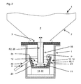
- Fig. 2 shows a supply device 1 for wood fuel pellets P with a pellet store 2 and a conveyor device 10.
- the conveyor 10 is in particular substantially below, that is arranged in the region of the geodesically lower end 3 of the pellet store 2.
- the conveyor 10 has a conveyor 14 for conveying wood fuel pellets P in a conveying direction r.
- the conveying device 10 is connected to an input side 11 with the pellet store 2 in connection.
- the conveying device 10 has a surface 12 starting from the inlet side 11 and aligned in the conveying direction r with a pitch.
- an actuator 13 for operating the conveyor 10 is provided.
- the conveying means 14 is mounted on the actuator 13.
- the storage is in particular designed such that the conveyor 14 is substantially rotationally fixed and fixed in position.
- the conveyor 14 is displaceable by means of the actuator 13 in a vibration F.
- the vibration F comprises a geodetic vertical vibration component y and a geodesic horizontal vibration component x.
- the latter is in particular a torsional vibration component.
- the conveyor 14 comprises a carrier tube 15 with a helically arranged on this surface 12.
- the surface 12 rises from the input side 11 in the conveying direction geodetic ge.
- the support tube 15 is aligned substantially vertically.
- the support tube widens conically from bottom to top.
- the surface 12 is guided radially on an inner side 21 of the support tube 15 and has a discharge edge 25 pointing radially outward.
- connection between the pellet store 12 and the conveying means 14 comprises a relief tube 18, which is aligned geodetically vertically and protrudes from above into the support tube 15. Within or below the support tube 15, a radial opening 20 in the region of the input side 11 of the conveyor 10 is formed.
- a rod 26 protrudes into the relief tube 18, which can be set into vibration F2 by means of an actuator 22.
- the rod 26 penetrates the relief tube 18 over its entire length.
- the rod 26 can be connected as shown by means of kinematic coupling with the actuator 13 for vibration excitation of the conveyor 14.
- the actuator 13 takes over the vibration excitation of the conveyor 14 and the rod 26th
- the support tube 15 On the input side 11 present wood fuel pellets P are moved by means of a vibration excitation F along the surface 12 on the inner side 21 of the support tube 15 upwards, in particular by so-called micro-prisms. In the radial outward direction, the support tube 15 effectively forms an edge elevation. Radially in the direction of the center of the support tube, such an edge elevation is dispensable, since the wood fuel pellets remain on the surface 12 due to a centripetal force.
- the conveyor 10 includes a conveyor 14 for conveying wood fuel pellets P in a conveying direction r.
- the conveyor device 10 is connected to an input side 11 with the pellet store 2 and has a surface 12 oriented from the input side 11 in the conveying direction r with a pitch.
- the surface 12 is coupled to an actuator 13.
- the conveyor 14 with the surface 12 is substantially non-rotatable and fixed in position and displaceable by means of the actuator 13 in vibration F.
- the vibration F comprises a geodetic vertical vibration component y and a geodetic horizontal vibration component x.
- the conveying device 10 is arranged with its input side 11 in the region of the geodetically underlying end 3 of the pellet store 2.
- the surface 12 extends from the input side 11 in the conveying direction r initially horizontally and finally falls off geodesically.
- the surface 12 has transversely to the conveying direction r aligned stages s1, s2, s3. Both the steps s1, s2, s3 and the different gradients contribute to a separation of the wood fuel pellets P on their way to the destination, or the unloading edge 25, at. So that the wood fuel pellets P can not leave the surface 12, edge elevations 23, 24 are arranged on the surface 12 along the direction of conveyance r.
- the conveying direction r is aligned substantially linearly.
Landscapes
- Engineering & Computer Science (AREA)
- Mechanical Engineering (AREA)
- Jigging Conveyors (AREA)
- Feeding Of Articles To Conveyors (AREA)
Description
- Die Erfindung betrifft eine Bereitstellungseinrichtung für Holzbrennstoffpellets gemäß dem Oberbegriff von Anspruch 1 sowie ein Verfahren zur Bereitstellung von Holzbrennstoffpellets nach Anspruch 8. Eine Bereitstellungseinrichtung, ist beispielsweise aus der
US-A-48775 284 - Holzbrennstoffpellets (oder einfach Holzpellets) sind ein biogener Brennstoff, der vollständig oder überwiegend aus Holz oder Sägenebenprodukten hergestellt wird. Es handelt sich hierbei um zum Beispiel nach der Europäischen Norm EN 14961 genormte, zylindrische Presslinge mit zumeist einem Durchmesser von fünf bis sechs Millimetern und einer Länge von acht bis dreißig Millimetern. Holzpellets werden in Pelletspeichern eingelagert, von wo aus sie einer Verbrennungseinrichtung zugeführt werden müssen. Hierfür werden unter anderem Förderschnecken eingesetzt, die in einem Trog liegen. Hiermit können Pellets in Richtung der Förderschnecke befördert werden. Nachteilig hierbei sind ein hoher Stromverbrauch und eine ungenaue Pelletdosierung in kleinen Leistungsbereichen. Die Folge sind ein erhöhter Brennstoffbedarf und eine unsaubere Verbrennungsregelung mit erhöhten Emissionen.
- Aufgabe der Erfindung ist es daher, die Nachteile des Stands der Technik zu überwinden, und eine Bereitstellungseinrichtung für Holzbrennstoffpellets zu entwickeln, die einen geringen Stromverbrauch aufweist sowie eine genaue Pelletdosierung über einen großen Leistungsbereich ermöglicht, um so den Brennstoffbedarf zu reduzieren und die Verbrennung emissionsarm regeln zu können. Die Pelletdosierung soll zudem sicher und dauerhaft möglich, sowie die Bereitstellungseinrichtung kostengünstig und auf einfache Weise herstellbar und betreibbar sein. Außerdem soll ein Verfahren entwickelt werden, dass diese Anforderungen erfüllen kann.
- Erfindungsgemäß wird dies mit den Merkmalen der Patentansprüche 1 und 8 gelöst. Vorteilhafte Weiterbildungen sind den Unteransprüchen zu entnehmen.
- Bei einer Bereitstellungseinrichtung für Holzbrennstoffpellets mit einem Pelletspeicher und einer Fördervorrichtung mit einem Fördermittel zum Fördern von Holzbrennstoffpellets in einer Förderrichtung, wobei die Fördervorrichtung mit einer Eingangsseite mit dem Pelletspeicher in Verbindung steht und eine von der Eingangsseite in die Förderrichtung ausgerichtete Oberfläche mit einer Steigung sowie einen Aktor aufweist, wobei, dass das Fördermittel im Wesentlichen drehfest und im Wesentlichen positionsfest gelagert ist sowie mittels des Aktors in Schwingung versetzbar ist, wobei die Schwingung eine geodätisch vertikale Schwingungskomponente umfasst.
- Der Vorteil einer derartigen Ausbildung ist, dass Holzpellets von der Eingangsseite in Richtung einer Verbrennungseinrichtung oder ähnlichem durch die vertikale Schwingungskomponente fortbewegbar sind. Ein Schwingungserreger hat einen geringen Stromverbrauch und die Schwingungen führen zu einer relativ kontinuierlichen Weiterbewegung der Holzpellets über einen sehr großen Leistungsbereich. Insbesondere ist auch eine sehr genaue Pelletdosierung bei sehr geringem Leistungsbereich möglich. Die Dosierung kann insbesondere durch eine Amplitudenmodulation oder durch eine Frequenzmodulation der Schwingungskomponenten erfolgen, die mithin bevorzugt nicht konstant sind. Im Weiteren wird die schwingungsbedingte Fortbewegung der Pellets auch als Mikrowurf bezeichnet. Mithin führt die genaue Dosierung zu einem geringeren Brennstoffbedarf und erlaubt eine genau angepasste emissionsarme Verbrennungsregelung.
- Die im Wesentlichen verdrehfeste und positionsfeste Lagerung sollte eine für die Schwingungserregung ausreichende Bewegungsfreiheit ermöglichen. Die drehfeste und positionsfeste Lagerung beschränkt sich mithin auf den Bewegungsbereich außerhalb der Schwingungsamplituden. Zur Schwingungserregung notwendige Aktoren können beispielsweise eine umlaufende Unwucht aufweisen. Derartige Aktoren sind kostengünstig und lassen sich über einen breiten Stellbereich regeln. Entsprechend genau kann die Pelletdosierung vorgenommen werden.
- Um den gesamten Inhalt des Pelletspeichers entnehmen zu können, ist die Fördervorrichtung mit ihrer Eingangsseite im Bereich des geodätisch unten liegenden Endes des Pelletspeichers angeordnet. Am gegenüberliegenden Ende der Fördervorrichtung ist das Fördermittel mit einer endseitigen Abladekante ausgestattet. Über diese Abladekante hinweg bewegte Holzbrennstoffpellets werden dann durch die Erdanziehungskraft bedingt weiterbewegt - entweder im freien Fall oder aber auf einer Rutsche.
Gemäß einer Weiterbildung der Erfindung ist vorgesehen, dass die Schwingung eine geodätisch horizontale Schwingungskomponente umfasst. Mittels einer solchen geodätisch horizontalen Schwingungskomponente kann ein auf der Oberfläche der Fördervorrichtung vertikal angeregtes Holzpellet bergauf transportiert werden - gewissermaßen durch horizontales Zurückbewegen der Oberfläche während der vertikal angeregten Mikrowurf-Flugphase und horizontales Vorwärtsbewegen der Oberfläche während der Mikrowurf-Kontaktphase. Eine ausschließlich geodätisch vertikale Schwingungsanregung ist hingegen sehr gut dafür geeignet, Holzbrennstoffpellets bergab zu transportieren. Der Impuls für eine horizontale Fortbewegung erfolgt dann mittels des Mikrowurf-Aufpralls der Brennstoffpellets auf die ansteigende Oberfläche. - Die Überlagerung der vertikalen Schwingungskomponente mit einer geodätisch horizontalen Schwingungskomponente ermöglicht nunmehr, die Eingangsseite und Teilbereiche des Pelletspeichers tiefer als den Zielort anzuordnen. So kann der Pelletspeicher beispielsweise im Erdreich versenkt werden. Als horizontale Schwingungskomponenten geeignet sind entweder lineare Bewegungen oder aber Drehschwingungen. Die Auswahl dieser horizontalen Schwingungskomponente hängt im Wesentlichen von der Förderrichtung ab, die z.B. linear, geradlinig oder spiralförmig erfolgen kann.
- Daher sieht eine Fortbildung der Erfindung vor, dass die Schwingung eine in Förderrichtung weisende Schwingungskomponente umfasst, also eine Kombination von geodätisch vertikalen und horizontalen Schwingungskomponenten. Auf diese Weise kann die Oberfläche unterhalb eines abgehobenen Holzpellets (Flugphase) zurück bewegt werden und sobald das Pellet wieder auf der Oberfläche aufliegt (Kontaktphase) wieder gemeinsam mit dem Holzpellet in Förderrichtung nach vorne bewegt werden.
- Dieses erfindungsgemäße Mikrowurfprinzip beschränkt sich dabei typischerweise auf Wurfhöhen der Holzpellets von Millimeter-Bruchteilen bis hin zu wenigen Millimetern. Die Vibrationen sorgen zudem dafür, dass die Holzpellets gleichmäßig über die Oberfläche der Fördervorrichtung verteilt sind. Gerade hierdurch ist eine sehr genaue Pelletdosierung möglich.
- In einer Variante der Erfindung ist vorgesehen, dass die Oberfläche von der Eingangsseite in Förderrichtung wenigstens zum Teil geodätisch ansteigt. Hierdurch ist es möglich, den Pelletspeicher tieferliegend anzuordnen als den Pelletzielort, wobei es sich insbesondere um eine Verbrennungseinrichtung handelt.
In einer Weiterbildung der Erfindung sind an der Oberfläche längs zur Förderrichtung wenigstens teilweise randseitige Überhöhungen (Randerhöhungen, Begrenzungen) angeordnet. Hierdurch wird verhindert, dass Pellets seitlich von der Fördervorrichtung herabfallen. Hierdurch ist der Stromverbrauch gering, da Pellets nicht unnötigerweise transportiert und anschließend wieder in die Ausgangsposition fallengelassen werden. Außerdem kann die Fördervorrichtung aus dem Bereich des Pelletspeichers hinaus verlaufen, ohne das Pellets in der Umgebung der Bereitstellungseinrichtung zu Boden fallen können. - Gemäß einer Weiterbildung der Erfindung ist vorgesehen, dass die Oberfläche mindestens in Teilbereichen eine Strukturierung und/oder Beschichtung aufweist, mittels der die Haftung beziehungsweise Reibung der Pellets auf der Oberfläche während der Kontaktphase des Mikrowurfs erhöht wird. Dies können beispielsweise quer zur Förderrichtung ausgerichtete Stufen, Rippen, Rillen, Noppen, Vertiefungen oder aber auch eine Gummibeschichtung sein. Mittels der Stufen lässt sich die Fortbewegungsgeschwindigkeit der Holzpellets auf der Oberfläche abschnittsweise unterteilen. Durch einen Steigungswechsel lässt sich auf einfache Weise die Fortbewegungsgeschwindigkeit der Holzpellets beeinflussen und somit eine Separierung der Pellets auf ihrem Weg zum Zielort vornehmen.
- In einer anderen Weiterentwicklung der erfindungsgemäßen Bereitstellungseinrichtung ist das Fördermittel am Aktor aufgehängt. Dies ermöglicht eine Positionierung des Aktors in einem leicht zugängigen Bereich. Außerdem ist die Lagerung des Fördermittels kostengünstig ausgestaltbar.
- Gemäß einer Variante der Erfindung ist die Förderrichtung im Wesentlichen linear ausgerichtet. Durch eine lineare Förderrichtung kann der Pelletspeicher beabstandet zum Zielort positioniert sein, ohne dass eine große Rutsche mit entsprechender Höhendifferenz erforderlich ist. So kann beispielsweise ein Pelletspeicher mit einer beabstandet zu diesem angeordneten Verbrennungseinrichtung verbunden werden. Andererseits kann der Pelletspeicher auch in mittelbarer oder unmittelbarer Nähe zur Verbrennungseinrichtung angeordnet sein, wie zum Beispiel ein an der Verbrennungseinrichtung vorhandener Zwischen- oder Tagesbehälter.
- Der Erfindung sieht vor, dass das Fördermittel ein Trägerrohr mit einer wendelförmig an dieser angeordneten Oberfläche umfasst. Ein solches Fördermittel kann Holzbrennstoffpellets auf engem Raum nach oben befördern. Eine lange geradlinig-lineare Rampe ist dann entbehrlich. Das Trägerrohr sollte hierbei im Wesentlichen vertikal ausgerichtet sein. Die wendelförmige Oberfläche kann sich dann an einem zylindrischen Trägerrohr oder aber an einem konischen Trägerrohr entlang winden.
- Auch können eine im Wesentlichen geradlinig-lineare Förderrichtung und eine wendelförmige Förderrichtung miteinander kombiniert werden. So ist es beispielsweise möglich die Holzbrennstoffpellets zunächst wendelförmig nach oben zu transportieren, bevor sie linear horizontal oder mit geringer Steigung weitertransportiert werden. Zur Anregung sind dann meist zwei separate Aktoren mit unterschiedlichen horizontalen sowie vertikalen Schwingungskomponenten erforderlich.
- Entsprechend einer speziellen Weiterbildung der erfindungsgemäßen Bereitstellungseinrichtung ist die Oberfläche wendelförmig und in Förderrichtung (r) geodätisch ansteigend auf einer äußeren Mantelfläche des Trägerrohres (15) um das Trägerrohr herumgeführt und mündet über eine Abladekante ins Innere des Trägerrohrs. Eine solche Anordnung ist besonders günstig, wenn der Pelletspeicher oberhalb des Zielortes angeordnet ist. Die Bereitstellungseinrichtung dient dann insbesondere der Dosierung, weniger jedoch einer Überwindung eines Höhenhindernisses oder einer Transportstrecke.
- Um die Anzahl der Holzbrennstoffpellets bereits vor dem Fördermittel zu reduzieren, ist das Fördermittel gemäß einer Variante der Erfindung wenigstens teilweise innerhalb des Pelletspeichers angeordnet sowie von einem geodätischen vertikal ausgerichteten Entlastungsrohr umgeben, das eine geodätisch oben liegende Pelletsperre ausbildet, wobei im Bereich der Eingangsseite der Fördervorrichtung eine radiale Öffnung für den Zutritt der Pellets zur Fördervorrichtung ausgebildet ist (zum Beispiel auch vollumfänglich). Damit wird ein Freiraum um das Trägerrohr geschaffen, der sich nicht mit Holzbrennstoffpellets füllt. Auf diese Weise ist die Fördervorrichtung wenigstens teilweise innerhalb des Pelletspeichers anordenbar. Es ist nur wenig oder kein Bauraum unterhalb des Pelletspeichers erforderlich. Bevorzugt ist das Entlastungsrohr dabei am Pelletspeicher befestigt.
- In einer anderen Weiterentwicklung der erfindungsgemäßen Bereitstellungseinrichtung ist vorgesehen, dass die Oberfläche wendelförmig und in Förderrichtung (r) geodätisch ansteigend auf einer inneren Mantelfläche des Trägerrohrs herumgeführt ist sowie eine radial nach außen weisende Abladekante aufweist, und dass der Pelletspeicher ein geodätisch unterseitiges und geodätisch vertikal ausgerichtetes Entlastungsrohr aufweist, dass von oben in das Trägerrohr hineinragt, wobei innerhalb des Trägerrohrs im Bereich der Eingangsseite der Fördervorrichtung eine radiale Öffnung für den Zutritt der Pellets zur Fördervorrichtung ausgebildet ist (zum Beispiel auch vollumfänglich). Plakativer ausgedrückt ragt das an den Pelletspeicher angeschlossene Entlastungsrohr von oben in eine schüsselartige Fördervorrichtung, an dessen Innenwandung sich die Oberfläche nach oben windet. Eine solche Ausbildung ist besonders kostengünstig fertigbar.
- Um ein Nachrutschen der Holzbrennstoffpellets aus dem Pelletspeicher in die Eingangsseite der Fördervorrichtung zu steuern und ein Verstopfen des Entlastungsrohrs durch sich verkeilende Holzbrennstoffpellets zu vermeiden, ragt eine Stange in das Entlastungsrohr hinein, die mittels eines Aktors in Schwingung versetzbar ist. Mittels einer schwingenden Stange lassen sich verkeilte Holzbrennstoffpellets lösen.
- Bevorzugt ist die Stange, welche in das Entlastungsrohr hineinragt, mittels kinematischer Kopplung mit dem Aktor zur Schwingungserregung des Fördermittels verbunden und somit ebenfalls in Schwingung versetzbar. Die vom Aktor erzeugten Schwingungen des Fördermittels können mit einer zusätzlichen Schwingung zur Erregung der Stange überlagert werden. Damit an keiner Stelle des Entlastungsrohrs eine Verstopfung auftreten kann, sollte die Stange das gesamte Entlastungsrohr durchdringen.
- Die Schwingamplituden des Aktors beziehungsweise des Fördermittels sowie der Stange sind durch das Entlastungsrohr unabhängig von der Pelletmenge im Pelletspeicher.
- Die Erfindung betrifft weiterhin ein Verfahren zur Bereitstellung von Holzbrennstoffpellets mittels einer Bereitstellungseinrichtung, wie sie zuvor beschrieben wurde, und das sich durch ein Zuführen von Holzbrennstoffpellets in die Eingangsseite der Fördervorrichtung durch Nachrutschen von Holzbrennstoffpellets aus dem Pelletspeicher, ein Beaufschlagen des Fördermittels mit einer Schwingung mittels des Aktors, sowie ein Transportieren der Holzbrennstoffpellets in Förderrichtung von der Eingangsseite über die Oberfläche mittels der durch den Aktor angeregten Schwingung und dadurch ausgelöste Mikrowürfe der Holzbrennstoffpellets auf der Oberfläche auszeichnet.
- Die Vorteile dieses Verfahrens entsprechen im Wesentlichen denen der Vorrichtung. So kann eine angeforderte Menge an Holzbrennstoffpellets besonders genau dosiert werden. Außerdem ist der Stromverbrauch zur Erregung der Schwingungen gering. Der Transport ist zudem sicher und dauerhaft gewährleistet. Ein weiterer Vorteil ist die geringe Gefahr für Verletzungen und Vorrichtungsschäden, da keine freiliegenden drehenden oder sich fortbewegenden Teile erforderlich sind.
- Eine Ausgestaltung des erfindungsgemäßen Verfahrens sieht vor, dass das Nachrutschen der Holzbrennstoffpellets aus dem Pelletspeicher in die Eingangsseite der Fördervorrichtung mittels einer im Entlastungsrohr angeordneten und mittels eines Aktors in Schwingungen versetzbaren Stange gesteuert wird. Dadurch können Fördermengen gezielt eingestellt und Verstopfungen vermieden werden.
- Eine andere Ausgestaltung des erfindungsgemäßen Verfahrens ist dadurch gekennzeichnet, dass der Aktor in Abhängigkeit einer Pelletfördermenge geregelt wird, die mittels eines am Förderweg angeordneten Sensor gemessenen wird. So kann die Pelletfördermenge beispielsweise auf akustischem, optischem oder elektromagnetischem Weg ermittelt werden (zum Beispiel zählen oder wiegen) und die Schwingungsamplitude und/oder Schwingungsdauer des Aktors beeinflussen. Hierüber lässt sich dann die Pelletförderleistung der Bereitstellungseinrichtung einstellen.
- Die Zeichnungen stellen Ausführungsbeispiele der Erfindung dar und zeigen in:
- Fig.1
- eine Bereitstellungseinrichtung, dessen Fördermittel wenigstens teilweise innerhalb des Pelletspeichers angeordnet sowie von einem geodätisch vertikal ausgerichteten Entlastungsrohr umgeben ist;
- Fig. 2
- eine Bereitstellungseinrichtung, die unterhalb eines Pelletspeichers angeordnet ist und eine Oberfläche aufweist, die sich radial an eine Innenseite eines Trägerrohrs bindet;
- Fig. 3
- eine Bereitstellungseinrichtung, deren Förderrichtung im Wesentlichen linear ausgerichtet ist.
-
Fig. 1 zeigt eine Bereitstellungseinrichtung 1 für Holzbrennstoffpellets P mit einem Pelletspeicher 2 und einer Fördervorrichtung 10 mit einem Fördermittel 14 zum Fördern von Holzbrennstoffpellets P in einer Förderrichtung r. Die Fördervorrichtung 10 steht mit einer Eingangsseite 11 mit dem Pelletspeicher 2 in Verbindung. Von der Eingangsseite 11 weist eine Oberfläche 12 mit einer Steigung in die Förderrichtung r. Außerdem verfügt die Bereitstellungseinrichtung über einen Aktor 13. Das Fördermittel 14 ist im Wesentlichen drehfest und positionsfest gelagert sowie mittels des Aktors 13 in eine Schwingung F versetzbar. Die Schwingung F umfasst eine geodätisch vertikale Schwingungskomponente y sowie eine geodätisch horizontale Schwingungskomponente x. Letztere ist insbesondere eine Drehschwingungskomponente. - Die Oberfläche 12 ist selbstredend von einem Trägerelement auszubilden, das jedoch in seiner Gestaltung abseits der Oberfläche 12 relativ frei ist. Ein solches Trägerelement kann beispielsweise eine Führungsbahn, eine Schiene, ein Profilkörper oder ein Freiformkörper sein. Bedingung ist lediglich eine relativ große Steifigkeit, bzw. Unflexibilität, da die Schwingungserregung über der Oberfläche 12 relativ gleich verteilt sein sollte, um an jeder Stelle eine vergleichbare Fortbewegungsgeschwindigkeit der Holzbrennstoffpellets bewirken zu können.
- Wie man erkennt, ist die Fördervorrichtung 10 mit ihrer Eingangsseite 11 im Bereich des geodätisch unten liegenden Endes 3 des Pelletspeichers 2 angeordnet. Von der Eingangsseite 11 windet sich die Oberfläche 12 des Fördermittels 14 um ein Trägerrohr 15. Das Trägerrohr 15 ist insbesondere zylindrisch. Die Oberfläche 12 ist radial um das Trägerrohr 15 herumgeführt und mündet über eine Abladekante 25 in das Innere 17 des Trägerrohrs 15. Mithin steigt die Oberfläche 12 von der Eingangsseite 11 in Förderrichtung r geodätisch an. Damit Holzbrennstoffpellets P nicht von der Oberfläche zurück in Richtung des unten liegenden Endes 3 des Pelletspeichers 2 zurückfallen können, hat die Oberfläche 12 längst zur Förderrichtung r eine randseitige Überhöhung 23. Gegenüberliegend bildet das Trägerrohr 14 ebenfalls eine randseitige Überhöhung 24 aus.
- Weiterhin erkennt man, dass das Fördermittel 14 am Aktor 13 aufgehängt ist. Das Fördermittel 14 und der Aktor 13 sind innerhalb des Pelletspeichers 2 angeordnet. Hierfür sind sie von einem geodätisch vertikal ausgerichteten Entlastungsrohr 18 umgeben, das eine geodätisch oben liegende Pelletsperre ausbildet. Im Bereich der Eingangsseite 11 der Fördervorrichtung 10 ist eine radiale Öffnung 20 vorgesehen, über die Holzbrennstoffpellets P in die Eingangsseite 11 der Fördervorrichtung 10 gelangen können.
- Durch eine modulierte Schwingungserregung der Oberfläche 12 mittels des Aktors 13 wandern die Holzbrennstoffpellets P von der Eingangsseite wendelförmig um das Trägerrohr 15 herum, bis sie schließlich über die Abladekante 25, die als Loch in der Wandung des Trägerrohrs 15 ausgebildet ist, in das Innere 17 des Trägerrohrs 15 gelangen und schließlich an ihren Bestimmungsort fallen, wobei es sich zum Beispiel um eine Rutsche oder unmittelbar um eine Verbrennungseinrichtung handelt.
-
Fig. 2 zeigt eine Bereitstellungseinrichtung 1 für Holzbrennstoffpellets P mit einem Pelletspeicher 2 und einer Fördervorrichtung 10. Die Fördervorrichtung 10 ist insbesondere im Wesentlichen unterhalb, das heißt im Bereich des geodätisch unten liegenden Endes 3 des Pelletspeichers 2 angeordnet. Die Fördervorrichtung 10 verfügt über ein Fördermittel 14 zum Fördern von Holzbrennstoffpellets P in einer Förderrichtung r. Dabei steht die Fördervorrichtung 10 mit einer Eingangsseite 11 mit dem Pelletspeicher 2 in Verbindung. Die Fördervorrichtung 10 verfügt über eine von der Eingangsseite 11 ausgehende sowie in Förderrichtung r ausgerichtete Oberfläche 12 mit einer Steigung. Außerdem ist ein Aktor 13 zum Betrieb der Fördervorrichtung 10 vorgesehen. Insbesondere ist das Fördermittel 14 auf dem Aktor 13 gelagert. Die Lagerung ist insbesondere derart ausgebildet, dass das Fördermittel 14 im Wesentlichen drehfest und positionsfest ist. Allerdings ist das Fördermittel 14 mittels des Aktors 13 in eine Schwingung F versetzbar. Die Schwingung F umfasst eine geodätisch vertikale Schwingungskomponente y und eine geodätisch horizontale Schwingungskomponente x. Letztere ist insbesondere eine Drehschwingungskomponente. Durch Überlagerung der vertikalen Schwingungskomponente x und der horizontalen Schwingungskomponente y ergibt sich eine in Förderrichtung r weisende Schwingungskomponente z. - Das Fördermittel 14 umfasst ein Trägerrohr 15 mit einer wendelförmig an dieser angeordneten Oberfläche 12. Die Oberfläche 12 steigt von der Eingangsseite 11 in Förderrichtung r geodätisch an. Dabei ist das Trägerrohr 15 im Wesentlichen vertikal ausgerichtet. Wie man erkennt, weitet sich das Trägerrohr von unten nach oben konisch auf. Zudem erkennt man, dass die Oberfläche 12 radial an einer Innenseite 21 des Trägerrohrs 15 herumgeführt ist, sowie eine radial nach außen weisende Abladekante 25 aufweist.
- Die Verbindung zwischen dem Pelletspeicher 12 und den Fördermittel 14 umfasst ein Entlastungsrohr 18, das geodätisch vertikal ausgerichtet ist und von oben in das Trägerrohr 15 hineinragt. Innerhalb bzw. unterhalb des Trägerrohrs 15 ist eine radiale Öffnung 20 im Bereich der Eingangsseite 11 der Fördervorrichtung 10 ausgebildet.
- Zur Vermeidung einer Verkeilung von Holzbrennstoffpellets P innerhalb des Entlastungsrohres 18, ragt eine Stange 26 in das Entlastungsrohr 18 hinein, die mittels eines Aktors 22 in Schwingung F2 versetzbar ist. Dabei durchdringt die Stange 26 das Entlastungsrohr 18 auf dessen gesamter Länge. Anstatt einen separaten Aktor 22 zur Schwingungserregung der Stange 26 vorzusehen, kann die Stange 26 wie dargestellt mittels kinematischer Kopplung mit dem Aktor 13 zur Schwingungserregung des Fördermittels 14 verbunden sein. Somit übernimmt der Aktor 13 die Schwingungserregung des Fördermittels 14 auch die der Stange 26.
- Auf der Eingangsseite 11 vorliegende Holzbrennstoffpellets P werden mittels einer Schwingungserregung F entlang der Oberfläche 12 auf der Innenseite 21 des Trägerrohrs 15 nach oben bewegt, insbesondere durch sogenannte Mikrowürfe. In radialer Richtung nach außen bildet das Trägerrohr 15 gewissermaßen eine randseitige Überhöhung aus. Radial in Richtung des Zentrums des Trägerrohrs ist eine solche randseitige Überhöhung entbehrlich, da die Holzbrennstoffpellets aufgrund einer zentripetalen Kraft auf der Oberfläche 12 verbleiben.
- In
Fig. 3 erkennt man eine Bereitstellungseinrichtung 1 für Holzbrennstoffpellets P mit einem Pelletspeicher 2 und einer Fördervorrichtung 10. Die Fördervorrichtung 10 umfasst ein Fördermittel 14 zum Fördern von Holzbrennstoffpellets P in einer Förderrichtung r. Die Fördervorrichtung 10 ist mit einer Eingangsseite 11 mit dem Pelletspeicher 2 verbunden und weist eine von der Eingangsseite 11 in die Förderrichtung r ausgerichtete Oberfläche 12 mit einer Steigung auf. Die Oberfläche 12 ist mit einem Aktor 13 gekoppelt. Das Fördermittel 14 mit der Oberfläche 12 ist im Wesentlichen drehfest und positionsfest gelagert sowie mittels des Aktors 13 in Schwingung F versetzbar. Die Schwingung F umfasst dabei eine geodätisch vertikale Schwingungskomponente y und eine geodätisch horizontale Schwingungskomponente x. - Weiterhin erkennt man, dass die Fördervorrichtung 10 mit ihrer Eingangsseite 11 im Bereich des geodätisch unten liegenden Endes 3 des Pelletspeichers 2 angeordnet ist. Die Oberfläche 12 verläuft von der Eingangsseite 11 in Förderrichtung r zunächst horizontal und fällt schließlich geodätisch ab. Dabei hat die Oberfläche 12 quer zur Förderrichtung r ausgerichtete Stufen s1, s2, s3. Sowohl die Stufen s1, s2, s3 als auch die unterschiedlichen Steigungen tragen zu einer Separierung der Holzbrennstoffpellets P auf ihrem Weg zum Zielort, bzw. der Abladekante 25, bei. Damit die Holzbrennstoffpellets P die Oberfläche 12 nicht verlassen können, sind an der Oberfläche 12 längs zur Förderrichtung r randseitige Überhöhungen 23, 24 angeordnet. Wie aus der Figur hervorgeht ist die Förderrichtung r im Wesentlichen linear ausgerichtet.
- Durch Erregung der Oberfläche 12 mit einer Schwingung F können nunmehr Holzbrennstoffpellets P mittels kleiner Mikrowürfe von der Eingangsseite 11 in Richtung der Abladekante 25 transportiert und gleichzeitig vereinzelt werden.
Bezugszeichenliste 1 Bereitstellungseinrichtung F Schwingung 2 Pelletspeicher F2 Schwingung 3 unten liegendes Ende P Holzbrennstoffpellets r Förderrichtung 10 Fördervorrichtung s1 erste Stufe 11 Eingangsseite s2 zweite Stufe 12 Oberfläche s3 dritte Stufe 13 Aktor 14 Fördermittel y vertikale 15 Trägerrohr Schwingungskomponente 17 Innere x horizontale 18 Entlastungsrohr Schwingungskomponente 20 radiale Öffnung z Schwingungskomponente in 21 Innenseite Förderrichtung 22 Aktor 23 randseitige Überhöhung 24 randseitige Überhöhung 25 Abladekante 26 Stange 30 Rutsche
Claims (10)
- Bereitstellungseinrichtung (1) für Holzbrennstoffpellets (P) mit einem Pelletspeicher (2) und einer Fördervorrichtung (10) mit einem Fördermittel (14) zum Fördern von Holzbrennstoffpellets (P) auf einem Förderweg in einer Förderrichtung (r) zu einem Zielort, wobei die Fördervorrichtung (10) mit einer Eingangsseite (11) mit dem Pelletspeicher (2) in Verbindung steht und eine von der Eingangsseite (11) in die Förderrichtung (r) ausgerichtete Oberfläche (12) mit einer Steigung sowie einen Aktor (13) aufweist, wobei
das Fördermittel (14) im Wesentlichen drehfest und im Wesentlichen positionsfest gelagert sowie mittels des Aktors (13) in Schwingung (F) versetzbar ist, wobei die Schwingung (F) eine geodätisch vertikale Schwingungskomponente (y) umfasst, wobei
das Fördermittel (14) ein Trägerrohr (15) mit einer wendelförmig an diesem angeordneten Oberfläche (12) umfasst, und wobei
die Oberfläche (12) wendelförmig und in Förderrichtung (r) geodätisch ansteigend auf einer inneren Mantelfläche des Trägerrohrs (15) herumgeführt ist sowie eine radial nach außen weisende Abladekante (25) aufweist,
dadurch gekennzeichnet, dass der Pelletspeicher (2) ein geodätisch unten angeordnetes und geodätisch vertikal ausgerichtetes Entlastungsrohr (18) aufweist, das von oben in das Trägerrohr (15) hineinragt, wobei innerhalb des Trägerrohrs (15) eine radiale Öffnung (20) im Bereich der Eingangsseite (11) der Fördervorrichtung (10) ausgebildet ist, und wobei
eine Stange (26) in das Entlastungsrohr (18) hineinragt, die mittels eines Aktors (22) in Schwingung (F2) versetzbar ist. - Bereitstellungseinrichtung (1) nach Anspruch 1,
dadurch gekennzeichnet, dass die Schwingung (F) eine geodätisch horizontale Schwingungskomponente (x) umfasst. - Bereitstellungseinrichtung (1) nach einem der Ansprüche 1 oder 2,
dadurch gekennzeichnet, dass die Schwingung (F) eine in Förderrichtung (r) weisende Schwingungskomponente (z) umfasst. - Bereitstellungseinrichtung (1) nach einem der vorhergehenden Ansprüche,
dadurch gekennzeichnet, dass an der Oberfläche (12) längs zur Förderrichtung (r) wenigstens teilweise randseitige Überhöhungen (23, 24) angeordnet sind. - Bereitstellungseinrichtung (1) nach einem der vorhergehenden Ansprüche,
dadurch gekennzeichnet, dass die Oberfläche (12) mindestens in Teilbereichen eine Strukturierung und/oder Beschichtung zur Erhöhung der Pellethaftung und/oder Pelletreibung aufweist, wobei Stufen (s1, s2, s3), Rippen, Rillen, Noppen, Vertiefungen oder Gummierungen zum Einsatz kommen. - Bereitstellungseinrichtung (1) nach einem der vorhergehenden Ansprüche,
dadurch gekennzeichnet, dass das Fördermittel (14) am Aktor (13) aufgehängt ist. - Bereitstellungseinrichtung (1) nach einem der vorhergehenden Ansprüche,
dadurch gekennzeichnet, dass die Förderrichtung (r) im Wesentlichen linear ausgerichtet ist. - Verfahren zur Bereitstellung von Holzbrennstoffpellets (P) mittels einer Bereitstellungseinrichtung (1) nach einem der vorhergehenden Ansprüche, gekennzeichnet durch folgende Schritte:a) Zuführen von Holzbrennstoffpellets (P) in die Eingangsseite (11) der Fördervorrichtung (10) durch Nachrutschen von Holzbrennstoffpellets (P) aus dem Pelletspeicher (2);b) Beaufschlagen des Fördermittels (14) mit einer Schwingung (F) mittels des Aktors (13);c) Transportieren der Holzbrennstoffpellets (P) in Förderrichtung (r) von der Eingangsseite (11) über die Oberfläche (12) mittels der durch den Aktor (13) angeregten Schwingung (F) und dadurch ausgelöste Mikrowürfe der Holzbrennstoffpellets (P) auf der Oberfläche (12).
- Verfahren nach Anspruch 8,
dadurch gekennzeichnet, dass das Nachrutschen der Holzbrennstoffpellets (P) aus dem Pelletspeicher (2) in die Eingangsseite (11) der Fördervorrichtung (10) mittels einer im Entlastungsrohr (18) angeordneten und mittels eines Aktors (22) in Schwingungen versetzbaren Stange (26) gesteuert wird. - Verfahren nach Anspruch 8 oder 9,
dadurch gekennzeichnet, dass der Aktor in Abhängigkeit einer mit einem am Förderweg angeordneten Sensor gemessenen Pelletfördermenge geregelt wird.
Applications Claiming Priority (1)
| Application Number | Priority Date | Filing Date | Title |
|---|---|---|---|
| DE102012010941A DE102012010941A1 (de) | 2012-06-04 | 2012-06-04 | Bereitstellungseinrichtung und -verfahren für Holzbrennstoffpellets |
Publications (2)
| Publication Number | Publication Date |
|---|---|
| EP2671824A1 EP2671824A1 (de) | 2013-12-11 |
| EP2671824B1 true EP2671824B1 (de) | 2016-01-13 |
Family
ID=48576743
Family Applications (1)
| Application Number | Title | Priority Date | Filing Date |
|---|---|---|---|
| EP13169529.8A Not-in-force EP2671824B1 (de) | 2012-06-04 | 2013-05-28 | Bereitstellungseinrichtung und- verfahren für Holzbrennstoffpellets |
Country Status (2)
| Country | Link |
|---|---|
| EP (1) | EP2671824B1 (de) |
| DE (1) | DE102012010941A1 (de) |
Families Citing this family (2)
| Publication number | Priority date | Publication date | Assignee | Title |
|---|---|---|---|---|
| EP3947213A4 (de) | 2019-04-05 | 2023-01-04 | Blue Sky Ventures (Ontario) Inc. | Vibrationsförderer zum fördern von artikeln und zugehörige füllmaschine und verfahren |
| EP4197942A1 (de) * | 2021-12-20 | 2023-06-21 | Asyril SA | Verfahren zur steuerung einer rüttelmaschine und entsprechendes steuersystem |
Family Cites Families (8)
| Publication number | Priority date | Publication date | Assignee | Title |
|---|---|---|---|---|
| DE974024C (de) * | 1950-02-23 | 1960-08-18 | Schenck Gmbh Carl | Schwingfoerderer mit einer um eine lotrechte oder zumindest steile Achse gewundenen Foerderbahn |
| DE1008649B (de) * | 1954-03-19 | 1957-05-16 | Karl Paul Wolfgang Nitsche | Transportrinne |
| DE1082607B (de) * | 1956-11-09 | 1960-06-02 | Metallgesellschaft Ag | Vorrichtung zum Kuehlen von heissem, kleinstueckigem Gut |
| DE3043009A1 (de) * | 1980-11-11 | 1982-05-27 | Wiendahl, Hans-Peter, Prof. Dr.-Ing., 3008 Garbsen | Ein- oder mehrkomponenten-schwingzufuehrungssystem |
| US4775284A (en) * | 1986-12-02 | 1988-10-04 | General Kinematics Corporation | Vertical mass flow conveyor |
| DE8805486U1 (de) * | 1988-04-26 | 1988-08-04 | Himpel, Manfred, Dipl.-Ing., 74348 Lauffen | Vibratorvorrichtung |
| DE19707248B4 (de) * | 1997-02-25 | 2005-09-22 | Cyrus Gmbh Schwingtechnik | Schwingförder-Vorrichtung und Schwingförder-Verfahren |
| US20070265429A1 (en) * | 2006-05-10 | 2007-11-15 | Hudson Andrew S | Use of a vibratory spiral elevator for crystallizing and/or drying of plastic pellets |
-
2012
- 2012-06-04 DE DE102012010941A patent/DE102012010941A1/de not_active Withdrawn
-
2013
- 2013-05-28 EP EP13169529.8A patent/EP2671824B1/de not_active Not-in-force
Also Published As
| Publication number | Publication date |
|---|---|
| DE102012010941A1 (de) | 2013-12-05 |
| EP2671824A1 (de) | 2013-12-11 |
Similar Documents
| Publication | Publication Date | Title |
|---|---|---|
| DE102007061574A1 (de) | Verfahren zur Füllstandsmessung | |
| DE102012008664B4 (de) | Verfahren zur Befüllung einer Dosierkammer sowie Vorrichtung hierfür | |
| WO2011127900A2 (de) | Vorrichtung zum herstellen dreidimensionaler modelle | |
| DE69201627T2 (de) | Einrichtung zum Fördern und volumetrischen Dosieren von Schüttgut. | |
| DE102008046434A1 (de) | Vorrichtung für die Zufuhr einer konstanten Menge an Schleifmittel | |
| EP2133670A1 (de) | Vorrichtung zum Erfassen eines Füllstands mit einem Dämpfungsbecher | |
| EP4281395A1 (de) | System zum transport von sterilen schüttfähigen verschlusselementen | |
| EP2671824A1 (de) | Bereitstellungseinrichtung und- verfahren für Holzbrennstoffpellets | |
| EP3718927B1 (de) | Fördertopf | |
| DE1938562C3 (de) | Vorrichtung zum Vereinzeln einer ungeordneten Menge von miteinander verhakten Teilen und zum Abgeben der vereinzelten Teile | |
| EP1152228A2 (de) | Dosiereinrichtung für das Befüllen von Gefässen mit kleinem Öffnungsquerschnitt | |
| EP3387227B1 (de) | Tanksystem für ein reduktionsmittel | |
| DE8704215U1 (de) | Vorrichtung zum Transport und zur baustellenseitigen Bevorratung von schüttgutartigen Baustoffen | |
| EP0407389B1 (de) | Einrichtung zum speichern und zuführen von kleinteilen | |
| EP1330951B1 (de) | Futtermischer | |
| EP3390788A1 (de) | Tanksystem für ein reduktionsmittel | |
| DE9105772U1 (de) | Vorrichtung zum Beladen eines Schüttgut-Sammelbehälters, insbesondere eines Müllwagen-Sammelbehälters | |
| DE3605890A1 (de) | Vorrichtung zum dosierten abgeben eines fluessigen produkts in einen fluessigkeitsbehaelter, insbesondere einen wasserbehaelter | |
| DE3202361C2 (de) | ||
| EP1826488A1 (de) | Brennmittelfördervorrichtung | |
| DE10336456A1 (de) | Fördervorrichtung zum Dosieren von fließfähigem Material | |
| WO2015028150A1 (de) | Dosiervorrichtung mit vorratsbehälter und austragsvorrichtung | |
| DE102010019801A1 (de) | Schuhbodensystem zur Austragung von kleinstückigem Schüttgut | |
| DE3601630C2 (de) | ||
| DE10036527A1 (de) | Verfahren und Einrichtung zum Befüllen eines Silos mit rieselfähigem Schüttgut |
Legal Events
| Date | Code | Title | Description |
|---|---|---|---|
| PUAI | Public reference made under article 153(3) epc to a published international application that has entered the european phase |
Free format text: ORIGINAL CODE: 0009012 |
|
| AK | Designated contracting states |
Kind code of ref document: A1 Designated state(s): AL AT BE BG CH CY CZ DE DK EE ES FI FR GB GR HR HU IE IS IT LI LT LU LV MC MK MT NL NO PL PT RO RS SE SI SK SM TR |
|
| AX | Request for extension of the european patent |
Extension state: BA ME |
|
| 17P | Request for examination filed |
Effective date: 20140611 |
|
| RBV | Designated contracting states (corrected) |
Designated state(s): AL AT BE BG CH CY CZ DE DK EE ES FI FR GB GR HR HU IE IS IT LI LT LU LV MC MK MT NL NO PL PT RO RS SE SI SK SM TR |
|
| GRAP | Despatch of communication of intention to grant a patent |
Free format text: ORIGINAL CODE: EPIDOSNIGR1 |
|
| INTG | Intention to grant announced |
Effective date: 20150708 |
|
| GRAS | Grant fee paid |
Free format text: ORIGINAL CODE: EPIDOSNIGR3 |
|
| GRAA | (expected) grant |
Free format text: ORIGINAL CODE: 0009210 |
|
| AK | Designated contracting states |
Kind code of ref document: B1 Designated state(s): AL AT BE BG CH CY CZ DE DK EE ES FI FR GB GR HR HU IE IS IT LI LT LU LV MC MK MT NL NO PL PT RO RS SE SI SK SM TR |
|
| REG | Reference to a national code |
Ref country code: GB Ref legal event code: FG4D Free format text: NOT ENGLISH |
|
| REG | Reference to a national code |
Ref country code: CH Ref legal event code: EP |
|
| REG | Reference to a national code |
Ref country code: IE Ref legal event code: FG4D Free format text: LANGUAGE OF EP DOCUMENT: GERMAN |
|
| REG | Reference to a national code |
Ref country code: AT Ref legal event code: REF Ref document number: 770352 Country of ref document: AT Kind code of ref document: T Effective date: 20160215 |
|
| REG | Reference to a national code |
Ref country code: DE Ref legal event code: R096 Ref document number: 502013001781 Country of ref document: DE |
|
| REG | Reference to a national code |
Ref country code: LT Ref legal event code: MG4D |
|
| REG | Reference to a national code |
Ref country code: NL Ref legal event code: MP Effective date: 20160113 |
|
| PG25 | Lapsed in a contracting state [announced via postgrant information from national office to epo] |
Ref country code: NL Free format text: LAPSE BECAUSE OF FAILURE TO SUBMIT A TRANSLATION OF THE DESCRIPTION OR TO PAY THE FEE WITHIN THE PRESCRIBED TIME-LIMIT Effective date: 20160113 |
|
| PG25 | Lapsed in a contracting state [announced via postgrant information from national office to epo] |
Ref country code: FI Free format text: LAPSE BECAUSE OF FAILURE TO SUBMIT A TRANSLATION OF THE DESCRIPTION OR TO PAY THE FEE WITHIN THE PRESCRIBED TIME-LIMIT Effective date: 20160113 Ref country code: HR Free format text: LAPSE BECAUSE OF FAILURE TO SUBMIT A TRANSLATION OF THE DESCRIPTION OR TO PAY THE FEE WITHIN THE PRESCRIBED TIME-LIMIT Effective date: 20160113 Ref country code: ES Free format text: LAPSE BECAUSE OF FAILURE TO SUBMIT A TRANSLATION OF THE DESCRIPTION OR TO PAY THE FEE WITHIN THE PRESCRIBED TIME-LIMIT Effective date: 20160113 Ref country code: IT Free format text: LAPSE BECAUSE OF FAILURE TO SUBMIT A TRANSLATION OF THE DESCRIPTION OR TO PAY THE FEE WITHIN THE PRESCRIBED TIME-LIMIT Effective date: 20160113 Ref country code: NO Free format text: LAPSE BECAUSE OF FAILURE TO SUBMIT A TRANSLATION OF THE DESCRIPTION OR TO PAY THE FEE WITHIN THE PRESCRIBED TIME-LIMIT Effective date: 20160413 Ref country code: GR Free format text: LAPSE BECAUSE OF FAILURE TO SUBMIT A TRANSLATION OF THE DESCRIPTION OR TO PAY THE FEE WITHIN THE PRESCRIBED TIME-LIMIT Effective date: 20160414 |
|
| PG25 | Lapsed in a contracting state [announced via postgrant information from national office to epo] |
Ref country code: RS Free format text: LAPSE BECAUSE OF FAILURE TO SUBMIT A TRANSLATION OF THE DESCRIPTION OR TO PAY THE FEE WITHIN THE PRESCRIBED TIME-LIMIT Effective date: 20160113 Ref country code: SE Free format text: LAPSE BECAUSE OF FAILURE TO SUBMIT A TRANSLATION OF THE DESCRIPTION OR TO PAY THE FEE WITHIN THE PRESCRIBED TIME-LIMIT Effective date: 20160113 Ref country code: BE Free format text: LAPSE BECAUSE OF NON-PAYMENT OF DUE FEES Effective date: 20160531 Ref country code: IS Free format text: LAPSE BECAUSE OF FAILURE TO SUBMIT A TRANSLATION OF THE DESCRIPTION OR TO PAY THE FEE WITHIN THE PRESCRIBED TIME-LIMIT Effective date: 20160513 Ref country code: PT Free format text: LAPSE BECAUSE OF FAILURE TO SUBMIT A TRANSLATION OF THE DESCRIPTION OR TO PAY THE FEE WITHIN THE PRESCRIBED TIME-LIMIT Effective date: 20160513 Ref country code: LV Free format text: LAPSE BECAUSE OF FAILURE TO SUBMIT A TRANSLATION OF THE DESCRIPTION OR TO PAY THE FEE WITHIN THE PRESCRIBED TIME-LIMIT Effective date: 20160113 Ref country code: LT Free format text: LAPSE BECAUSE OF FAILURE TO SUBMIT A TRANSLATION OF THE DESCRIPTION OR TO PAY THE FEE WITHIN THE PRESCRIBED TIME-LIMIT Effective date: 20160113 Ref country code: PL Free format text: LAPSE BECAUSE OF FAILURE TO SUBMIT A TRANSLATION OF THE DESCRIPTION OR TO PAY THE FEE WITHIN THE PRESCRIBED TIME-LIMIT Effective date: 20160113 |
|
| REG | Reference to a national code |
Ref country code: DE Ref legal event code: R097 Ref document number: 502013001781 Country of ref document: DE |
|
| PG25 | Lapsed in a contracting state [announced via postgrant information from national office to epo] |
Ref country code: DK Free format text: LAPSE BECAUSE OF FAILURE TO SUBMIT A TRANSLATION OF THE DESCRIPTION OR TO PAY THE FEE WITHIN THE PRESCRIBED TIME-LIMIT Effective date: 20160113 Ref country code: EE Free format text: LAPSE BECAUSE OF FAILURE TO SUBMIT A TRANSLATION OF THE DESCRIPTION OR TO PAY THE FEE WITHIN THE PRESCRIBED TIME-LIMIT Effective date: 20160113 |
|
| PLBE | No opposition filed within time limit |
Free format text: ORIGINAL CODE: 0009261 |
|
| STAA | Information on the status of an ep patent application or granted ep patent |
Free format text: STATUS: NO OPPOSITION FILED WITHIN TIME LIMIT |
|
| PG25 | Lapsed in a contracting state [announced via postgrant information from national office to epo] |
Ref country code: RO Free format text: LAPSE BECAUSE OF FAILURE TO SUBMIT A TRANSLATION OF THE DESCRIPTION OR TO PAY THE FEE WITHIN THE PRESCRIBED TIME-LIMIT Effective date: 20160113 Ref country code: CZ Free format text: LAPSE BECAUSE OF FAILURE TO SUBMIT A TRANSLATION OF THE DESCRIPTION OR TO PAY THE FEE WITHIN THE PRESCRIBED TIME-LIMIT Effective date: 20160113 Ref country code: SK Free format text: LAPSE BECAUSE OF FAILURE TO SUBMIT A TRANSLATION OF THE DESCRIPTION OR TO PAY THE FEE WITHIN THE PRESCRIBED TIME-LIMIT Effective date: 20160113 Ref country code: SM Free format text: LAPSE BECAUSE OF FAILURE TO SUBMIT A TRANSLATION OF THE DESCRIPTION OR TO PAY THE FEE WITHIN THE PRESCRIBED TIME-LIMIT Effective date: 20160113 |
|
| 26N | No opposition filed |
Effective date: 20161014 |
|
| PG25 | Lapsed in a contracting state [announced via postgrant information from national office to epo] |
Ref country code: LU Free format text: LAPSE BECAUSE OF FAILURE TO SUBMIT A TRANSLATION OF THE DESCRIPTION OR TO PAY THE FEE WITHIN THE PRESCRIBED TIME-LIMIT Effective date: 20160528 |
|
| REG | Reference to a national code |
Ref country code: IE Ref legal event code: MM4A |
|
| PG25 | Lapsed in a contracting state [announced via postgrant information from national office to epo] |
Ref country code: BG Free format text: LAPSE BECAUSE OF FAILURE TO SUBMIT A TRANSLATION OF THE DESCRIPTION OR TO PAY THE FEE WITHIN THE PRESCRIBED TIME-LIMIT Effective date: 20160413 Ref country code: SI Free format text: LAPSE BECAUSE OF FAILURE TO SUBMIT A TRANSLATION OF THE DESCRIPTION OR TO PAY THE FEE WITHIN THE PRESCRIBED TIME-LIMIT Effective date: 20160113 |
|
| REG | Reference to a national code |
Ref country code: FR Ref legal event code: ST Effective date: 20170131 |
|
| PG25 | Lapsed in a contracting state [announced via postgrant information from national office to epo] |
Ref country code: FR Free format text: LAPSE BECAUSE OF NON-PAYMENT OF DUE FEES Effective date: 20160531 |
|
| PG25 | Lapsed in a contracting state [announced via postgrant information from national office to epo] |
Ref country code: IE Free format text: LAPSE BECAUSE OF NON-PAYMENT OF DUE FEES Effective date: 20160528 |
|
| GBPC | Gb: european patent ceased through non-payment of renewal fee |
Effective date: 20170528 |
|
| PG25 | Lapsed in a contracting state [announced via postgrant information from national office to epo] |
Ref country code: GB Free format text: LAPSE BECAUSE OF NON-PAYMENT OF DUE FEES Effective date: 20170528 |
|
| PG25 | Lapsed in a contracting state [announced via postgrant information from national office to epo] |
Ref country code: CY Free format text: LAPSE BECAUSE OF FAILURE TO SUBMIT A TRANSLATION OF THE DESCRIPTION OR TO PAY THE FEE WITHIN THE PRESCRIBED TIME-LIMIT Effective date: 20160113 Ref country code: HU Free format text: LAPSE BECAUSE OF FAILURE TO SUBMIT A TRANSLATION OF THE DESCRIPTION OR TO PAY THE FEE WITHIN THE PRESCRIBED TIME-LIMIT; INVALID AB INITIO Effective date: 20130528 |
|
| PG25 | Lapsed in a contracting state [announced via postgrant information from national office to epo] |
Ref country code: MK Free format text: LAPSE BECAUSE OF FAILURE TO SUBMIT A TRANSLATION OF THE DESCRIPTION OR TO PAY THE FEE WITHIN THE PRESCRIBED TIME-LIMIT Effective date: 20160113 Ref country code: MC Free format text: LAPSE BECAUSE OF FAILURE TO SUBMIT A TRANSLATION OF THE DESCRIPTION OR TO PAY THE FEE WITHIN THE PRESCRIBED TIME-LIMIT Effective date: 20160113 Ref country code: TR Free format text: LAPSE BECAUSE OF FAILURE TO SUBMIT A TRANSLATION OF THE DESCRIPTION OR TO PAY THE FEE WITHIN THE PRESCRIBED TIME-LIMIT Effective date: 20160113 Ref country code: MT Free format text: LAPSE BECAUSE OF FAILURE TO SUBMIT A TRANSLATION OF THE DESCRIPTION OR TO PAY THE FEE WITHIN THE PRESCRIBED TIME-LIMIT Effective date: 20160113 |
|
| PG25 | Lapsed in a contracting state [announced via postgrant information from national office to epo] |
Ref country code: AL Free format text: LAPSE BECAUSE OF FAILURE TO SUBMIT A TRANSLATION OF THE DESCRIPTION OR TO PAY THE FEE WITHIN THE PRESCRIBED TIME-LIMIT Effective date: 20160113 |
|
| PGFP | Annual fee paid to national office [announced via postgrant information from national office to epo] |
Ref country code: CH Payment date: 20190523 Year of fee payment: 7 |
|
| PGFP | Annual fee paid to national office [announced via postgrant information from national office to epo] |
Ref country code: AT Payment date: 20190517 Year of fee payment: 7 Ref country code: DE Payment date: 20190716 Year of fee payment: 7 |
|
| REG | Reference to a national code |
Ref country code: DE Ref legal event code: R119 Ref document number: 502013001781 Country of ref document: DE |
|
| REG | Reference to a national code |
Ref country code: AT Ref legal event code: MM01 Ref document number: 770352 Country of ref document: AT Kind code of ref document: T Effective date: 20200528 |
|
| PG25 | Lapsed in a contracting state [announced via postgrant information from national office to epo] |
Ref country code: CH Free format text: LAPSE BECAUSE OF NON-PAYMENT OF DUE FEES Effective date: 20200531 Ref country code: LI Free format text: LAPSE BECAUSE OF NON-PAYMENT OF DUE FEES Effective date: 20200531 Ref country code: AT Free format text: LAPSE BECAUSE OF NON-PAYMENT OF DUE FEES Effective date: 20200528 |
|
| PG25 | Lapsed in a contracting state [announced via postgrant information from national office to epo] |
Ref country code: DE Free format text: LAPSE BECAUSE OF NON-PAYMENT OF DUE FEES Effective date: 20201201 |