EP2665876B1 - Wärmedämmverbundsystem - Google Patents
Wärmedämmverbundsystem Download PDFInfo
- Publication number
- EP2665876B1 EP2665876B1 EP12700805.0A EP12700805A EP2665876B1 EP 2665876 B1 EP2665876 B1 EP 2665876B1 EP 12700805 A EP12700805 A EP 12700805A EP 2665876 B1 EP2665876 B1 EP 2665876B1
- Authority
- EP
- European Patent Office
- Prior art keywords
- thermal insulation
- fibres
- layer
- building wall
- inorganic
- Prior art date
- Legal status (The legal status is an assumption and is not a legal conclusion. Google has not performed a legal analysis and makes no representation as to the accuracy of the status listed.)
- Revoked
Links
- 238000009413 insulation Methods 0.000 title claims description 187
- 239000002131 composite material Substances 0.000 title claims description 52
- 239000011230 binding agent Substances 0.000 claims description 81
- 238000005253 cladding Methods 0.000 claims description 79
- 239000004964 aerogel Substances 0.000 claims description 67
- 238000000576 coating method Methods 0.000 claims description 28
- 239000011248 coating agent Substances 0.000 claims description 26
- NTHWMYGWWRZVTN-UHFFFAOYSA-N sodium silicate Chemical compound [Na+].[Na+].[O-][Si]([O-])=O NTHWMYGWWRZVTN-UHFFFAOYSA-N 0.000 claims description 20
- 239000000463 material Substances 0.000 claims description 18
- 239000000203 mixture Substances 0.000 claims description 14
- 239000003365 glass fiber Substances 0.000 claims description 13
- 239000002759 woven fabric Substances 0.000 claims description 12
- 239000011256 inorganic filler Substances 0.000 claims description 11
- 229910003475 inorganic filler Inorganic materials 0.000 claims description 11
- 239000004568 cement Substances 0.000 claims description 7
- GWEVSGVZZGPLCZ-UHFFFAOYSA-N Titan oxide Chemical compound O=[Ti]=O GWEVSGVZZGPLCZ-UHFFFAOYSA-N 0.000 claims description 6
- 238000005304 joining Methods 0.000 claims description 6
- -1 polypropylene Polymers 0.000 claims description 6
- 230000002209 hydrophobic effect Effects 0.000 claims description 5
- RLQWHDODQVOVKU-UHFFFAOYSA-N tetrapotassium;silicate Chemical compound [K+].[K+].[K+].[K+].[O-][Si]([O-])([O-])[O-] RLQWHDODQVOVKU-UHFFFAOYSA-N 0.000 claims description 5
- UQSXHKLRYXJYBZ-UHFFFAOYSA-N Iron oxide Chemical compound [Fe]=O UQSXHKLRYXJYBZ-UHFFFAOYSA-N 0.000 claims description 4
- AMWRITDGCCNYAT-UHFFFAOYSA-L hydroxy(oxo)manganese;manganese Chemical compound [Mn].O[Mn]=O.O[Mn]=O AMWRITDGCCNYAT-UHFFFAOYSA-L 0.000 claims description 4
- SPAGIJMPHSUYSE-UHFFFAOYSA-N Magnesium peroxide Chemical group [Mg+2].[O-][O-] SPAGIJMPHSUYSE-UHFFFAOYSA-N 0.000 claims description 3
- 239000004743 Polypropylene Substances 0.000 claims description 3
- 239000004793 Polystyrene Substances 0.000 claims description 3
- 239000003513 alkali Substances 0.000 claims description 3
- 229910000323 aluminium silicate Inorganic materials 0.000 claims description 3
- 229910052751 metal Inorganic materials 0.000 claims description 3
- 239000002184 metal Substances 0.000 claims description 3
- 229920000728 polyester Polymers 0.000 claims description 3
- 229920001155 polypropylene Polymers 0.000 claims description 3
- 229920002223 polystyrene Polymers 0.000 claims description 3
- 239000004408 titanium dioxide Substances 0.000 claims description 3
- 229920002748 Basalt fiber Polymers 0.000 claims description 2
- ZOXJGFHDIHLPTG-UHFFFAOYSA-N Boron Chemical compound [B] ZOXJGFHDIHLPTG-UHFFFAOYSA-N 0.000 claims description 2
- RTAQQCXQSZGOHL-UHFFFAOYSA-N Titanium Chemical compound [Ti] RTAQQCXQSZGOHL-UHFFFAOYSA-N 0.000 claims description 2
- 239000004411 aluminium Substances 0.000 claims description 2
- 229910052782 aluminium Inorganic materials 0.000 claims description 2
- XAGFODPZIPBFFR-UHFFFAOYSA-N aluminium Chemical compound [Al] XAGFODPZIPBFFR-UHFFFAOYSA-N 0.000 claims description 2
- 229910052796 boron Inorganic materials 0.000 claims description 2
- 239000000919 ceramic Substances 0.000 claims description 2
- LIKBJVNGSGBSGK-UHFFFAOYSA-N iron(3+);oxygen(2-) Chemical compound [O-2].[O-2].[O-2].[Fe+3].[Fe+3] LIKBJVNGSGBSGK-UHFFFAOYSA-N 0.000 claims description 2
- JEIPFZHSYJVQDO-UHFFFAOYSA-N iron(III) oxide Inorganic materials O=[Fe]O[Fe]=O JEIPFZHSYJVQDO-UHFFFAOYSA-N 0.000 claims description 2
- RVTZCBVAJQQJTK-UHFFFAOYSA-N oxygen(2-);zirconium(4+) Chemical compound [O-2].[O-2].[Zr+4] RVTZCBVAJQQJTK-UHFFFAOYSA-N 0.000 claims description 2
- 239000011435 rock Substances 0.000 claims description 2
- 239000010703 silicon Substances 0.000 claims description 2
- 229910052710 silicon Inorganic materials 0.000 claims description 2
- HBMJWWWQQXIZIP-UHFFFAOYSA-N silicon carbide Chemical compound [Si+]#[C-] HBMJWWWQQXIZIP-UHFFFAOYSA-N 0.000 claims description 2
- 229910010271 silicon carbide Inorganic materials 0.000 claims description 2
- XOLBLPGZBRYERU-UHFFFAOYSA-N tin dioxide Chemical compound O=[Sn]=O XOLBLPGZBRYERU-UHFFFAOYSA-N 0.000 claims description 2
- 229910001887 tin oxide Inorganic materials 0.000 claims description 2
- 239000010936 titanium Substances 0.000 claims description 2
- 229910052719 titanium Inorganic materials 0.000 claims description 2
- MTPVUVINMAGMJL-UHFFFAOYSA-N trimethyl(1,1,2,2,2-pentafluoroethyl)silane Chemical compound C[Si](C)(C)C(F)(F)C(F)(F)F MTPVUVINMAGMJL-UHFFFAOYSA-N 0.000 claims description 2
- 229910001928 zirconium oxide Inorganic materials 0.000 claims description 2
- GFQYVLUOOAAOGM-UHFFFAOYSA-N zirconium(iv) silicate Chemical compound [Zr+4].[O-][Si]([O-])([O-])[O-] GFQYVLUOOAAOGM-UHFFFAOYSA-N 0.000 claims description 2
- 239000010410 layer Substances 0.000 description 88
- 238000000034 method Methods 0.000 description 25
- 239000000853 adhesive Substances 0.000 description 21
- 230000001070 adhesive effect Effects 0.000 description 21
- VYPSYNLAJGMNEJ-UHFFFAOYSA-N Silicium dioxide Chemical compound O=[Si]=O VYPSYNLAJGMNEJ-UHFFFAOYSA-N 0.000 description 18
- 239000004115 Sodium Silicate Substances 0.000 description 15
- 229910052911 sodium silicate Inorganic materials 0.000 description 15
- BPQQTUXANYXVAA-UHFFFAOYSA-N Orthosilicate Chemical compound [O-][Si]([O-])([O-])[O-] BPQQTUXANYXVAA-UHFFFAOYSA-N 0.000 description 13
- XLYOFNOQVPJJNP-UHFFFAOYSA-N water Substances O XLYOFNOQVPJJNP-UHFFFAOYSA-N 0.000 description 13
- 238000002485 combustion reaction Methods 0.000 description 11
- 239000000843 powder Substances 0.000 description 9
- 239000000377 silicon dioxide Substances 0.000 description 9
- 238000004519 manufacturing process Methods 0.000 description 8
- 239000000758 substrate Substances 0.000 description 8
- 238000001035 drying Methods 0.000 description 7
- 238000000352 supercritical drying Methods 0.000 description 6
- 239000000080 wetting agent Substances 0.000 description 6
- 239000000945 filler Substances 0.000 description 5
- 239000000017 hydrogel Substances 0.000 description 5
- 230000007774 longterm Effects 0.000 description 5
- 239000004570 mortar (masonry) Substances 0.000 description 5
- 239000002245 particle Substances 0.000 description 5
- 235000019353 potassium silicate Nutrition 0.000 description 5
- 239000000126 substance Substances 0.000 description 5
- 239000010751 BS 2869 Class A2 Substances 0.000 description 4
- KAKZBPTYRLMSJV-UHFFFAOYSA-N Butadiene Chemical compound C=CC=C KAKZBPTYRLMSJV-UHFFFAOYSA-N 0.000 description 4
- PPBRXRYQALVLMV-UHFFFAOYSA-N Styrene Chemical compound C=CC1=CC=CC=C1 PPBRXRYQALVLMV-UHFFFAOYSA-N 0.000 description 4
- 229910052681 coesite Inorganic materials 0.000 description 4
- 239000007859 condensation product Substances 0.000 description 4
- 229910052906 cristobalite Inorganic materials 0.000 description 4
- 238000001704 evaporation Methods 0.000 description 4
- 230000008020 evaporation Effects 0.000 description 4
- LEQAOMBKQFMDFZ-UHFFFAOYSA-N glyoxal Chemical compound O=CC=O LEQAOMBKQFMDFZ-UHFFFAOYSA-N 0.000 description 4
- 229910052500 inorganic mineral Inorganic materials 0.000 description 4
- 238000011068 loading method Methods 0.000 description 4
- 239000011707 mineral Substances 0.000 description 4
- 235000010755 mineral Nutrition 0.000 description 4
- 239000011490 mineral wool Substances 0.000 description 4
- 229920000642 polymer Polymers 0.000 description 4
- KKCBUQHMOMHUOY-UHFFFAOYSA-N sodium oxide Chemical compound [O-2].[Na+].[Na+] KKCBUQHMOMHUOY-UHFFFAOYSA-N 0.000 description 4
- 239000007787 solid Substances 0.000 description 4
- 238000005507 spraying Methods 0.000 description 4
- 229910052682 stishovite Inorganic materials 0.000 description 4
- 229910052905 tridymite Inorganic materials 0.000 description 4
- HEMHJVSKTPXQMS-UHFFFAOYSA-M Sodium hydroxide Chemical compound [OH-].[Na+] HEMHJVSKTPXQMS-UHFFFAOYSA-M 0.000 description 3
- XTXRWKRVRITETP-UHFFFAOYSA-N Vinyl acetate Chemical compound CC(=O)OC=C XTXRWKRVRITETP-UHFFFAOYSA-N 0.000 description 3
- 238000004026 adhesive bonding Methods 0.000 description 3
- 239000002585 base Substances 0.000 description 3
- 230000005540 biological transmission Effects 0.000 description 3
- 230000015572 biosynthetic process Effects 0.000 description 3
- 238000010276 construction Methods 0.000 description 3
- 238000001723 curing Methods 0.000 description 3
- 239000004744 fabric Substances 0.000 description 3
- 239000000499 gel Substances 0.000 description 3
- 238000010438 heat treatment Methods 0.000 description 3
- 239000012774 insulation material Substances 0.000 description 3
- 239000000049 pigment Substances 0.000 description 3
- 238000006116 polymerization reaction Methods 0.000 description 3
- 229920001296 polysiloxane Polymers 0.000 description 3
- 239000000047 product Substances 0.000 description 3
- 230000003014 reinforcing effect Effects 0.000 description 3
- 239000007921 spray Substances 0.000 description 3
- 239000004094 surface-active agent Substances 0.000 description 3
- OAOABCKPVCUNKO-UHFFFAOYSA-N 8-methyl Nonanoic acid Chemical compound CC(C)CCCCCCC(O)=O OAOABCKPVCUNKO-UHFFFAOYSA-N 0.000 description 2
- NIXOWILDQLNWCW-UHFFFAOYSA-M Acrylate Chemical compound [O-]C(=O)C=C NIXOWILDQLNWCW-UHFFFAOYSA-M 0.000 description 2
- VTYYLEPIZMXCLO-UHFFFAOYSA-L Calcium carbonate Chemical compound [Ca+2].[O-]C([O-])=O VTYYLEPIZMXCLO-UHFFFAOYSA-L 0.000 description 2
- LZZYPRNAOMGNLH-UHFFFAOYSA-M Cetrimonium bromide Chemical compound [Br-].CCCCCCCCCCCCCCCC[N+](C)(C)C LZZYPRNAOMGNLH-UHFFFAOYSA-M 0.000 description 2
- RTZKZFJDLAIYFH-UHFFFAOYSA-N Diethyl ether Chemical compound CCOCC RTZKZFJDLAIYFH-UHFFFAOYSA-N 0.000 description 2
- VGGSQFUCUMXWEO-UHFFFAOYSA-N Ethene Chemical compound C=C VGGSQFUCUMXWEO-UHFFFAOYSA-N 0.000 description 2
- 239000005977 Ethylene Substances 0.000 description 2
- AEMRFAOFKBGASW-UHFFFAOYSA-N Glycolic acid Chemical compound OCC(O)=O AEMRFAOFKBGASW-UHFFFAOYSA-N 0.000 description 2
- 229920000877 Melamine resin Polymers 0.000 description 2
- 241000183024 Populus tremula Species 0.000 description 2
- 239000011398 Portland cement Substances 0.000 description 2
- 239000004111 Potassium silicate Substances 0.000 description 2
- DBMJMQXJHONAFJ-UHFFFAOYSA-M Sodium laurylsulphate Chemical compound [Na+].CCCCCCCCCCCCOS([O-])(=O)=O DBMJMQXJHONAFJ-UHFFFAOYSA-M 0.000 description 2
- 229920001807 Urea-formaldehyde Polymers 0.000 description 2
- 239000002253 acid Substances 0.000 description 2
- 239000000654 additive Substances 0.000 description 2
- 125000000129 anionic group Chemical group 0.000 description 2
- 239000007864 aqueous solution Substances 0.000 description 2
- AXCZMVOFGPJBDE-UHFFFAOYSA-L calcium dihydroxide Chemical compound [OH-].[OH-].[Ca+2] AXCZMVOFGPJBDE-UHFFFAOYSA-L 0.000 description 2
- 239000000920 calcium hydroxide Substances 0.000 description 2
- 235000011116 calcium hydroxide Nutrition 0.000 description 2
- 229910001861 calcium hydroxide Inorganic materials 0.000 description 2
- 125000002091 cationic group Chemical group 0.000 description 2
- 238000006243 chemical reaction Methods 0.000 description 2
- 239000003795 chemical substances by application Substances 0.000 description 2
- 239000000470 constituent Substances 0.000 description 2
- 230000008602 contraction Effects 0.000 description 2
- 229920001577 copolymer Polymers 0.000 description 2
- 239000012792 core layer Substances 0.000 description 2
- 230000018044 dehydration Effects 0.000 description 2
- 238000006297 dehydration reaction Methods 0.000 description 2
- HNPSIPDUKPIQMN-UHFFFAOYSA-N dioxosilane;oxo(oxoalumanyloxy)alumane Chemical class O=[Si]=O.O=[Al]O[Al]=O HNPSIPDUKPIQMN-UHFFFAOYSA-N 0.000 description 2
- 239000002270 dispersing agent Substances 0.000 description 2
- 239000006185 dispersion Substances 0.000 description 2
- 239000006260 foam Substances 0.000 description 2
- IVJISJACKSSFGE-UHFFFAOYSA-N formaldehyde;1,3,5-triazine-2,4,6-triamine Chemical compound O=C.NC1=NC(N)=NC(N)=N1 IVJISJACKSSFGE-UHFFFAOYSA-N 0.000 description 2
- 229920000876 geopolymer Polymers 0.000 description 2
- 229940015043 glyoxal Drugs 0.000 description 2
- 229920001519 homopolymer Polymers 0.000 description 2
- 239000004572 hydraulic lime Substances 0.000 description 2
- 238000009434 installation Methods 0.000 description 2
- NLYAJNPCOHFWQQ-UHFFFAOYSA-N kaolin Chemical compound O.O.O=[Al]O[Si](=O)O[Si](=O)O[Al]=O NLYAJNPCOHFWQQ-UHFFFAOYSA-N 0.000 description 2
- 229920006112 polar polymer Polymers 0.000 description 2
- ODGAOXROABLFNM-UHFFFAOYSA-N polynoxylin Chemical compound O=C.NC(N)=O ODGAOXROABLFNM-UHFFFAOYSA-N 0.000 description 2
- 229920000915 polyvinyl chloride Polymers 0.000 description 2
- 239000004800 polyvinyl chloride Substances 0.000 description 2
- NNHHDJVEYQHLHG-UHFFFAOYSA-N potassium silicate Chemical compound [K+].[K+].[O-][Si]([O-])=O NNHHDJVEYQHLHG-UHFFFAOYSA-N 0.000 description 2
- 229910052913 potassium silicate Inorganic materials 0.000 description 2
- 238000001556 precipitation Methods 0.000 description 2
- 238000009877 rendering Methods 0.000 description 2
- 238000000518 rheometry Methods 0.000 description 2
- 229920002050 silicone resin Polymers 0.000 description 2
- 239000000243 solution Substances 0.000 description 2
- 239000002904 solvent Substances 0.000 description 2
- 229920002994 synthetic fiber Polymers 0.000 description 2
- 229920003002 synthetic resin Polymers 0.000 description 2
- 239000000057 synthetic resin Substances 0.000 description 2
- 239000004753 textile Substances 0.000 description 2
- 239000002562 thickening agent Substances 0.000 description 2
- 229920001567 vinyl ester resin Polymers 0.000 description 2
- 125000000391 vinyl group Chemical group [H]C([*])=C([H])[H] 0.000 description 2
- NJVOHKFLBKQLIZ-UHFFFAOYSA-N (2-ethenylphenyl) prop-2-enoate Chemical compound C=CC(=O)OC1=CC=CC=C1C=C NJVOHKFLBKQLIZ-UHFFFAOYSA-N 0.000 description 1
- HRPVXLWXLXDGHG-UHFFFAOYSA-N Acrylamide Chemical compound NC(=O)C=C HRPVXLWXLXDGHG-UHFFFAOYSA-N 0.000 description 1
- 239000005995 Aluminium silicate Substances 0.000 description 1
- 244000025254 Cannabis sativa Species 0.000 description 1
- 235000012766 Cannabis sativa ssp. sativa var. sativa Nutrition 0.000 description 1
- 235000012765 Cannabis sativa ssp. sativa var. spontanea Nutrition 0.000 description 1
- 239000004971 Cross linker Substances 0.000 description 1
- LFQSCWFLJHTTHZ-UHFFFAOYSA-N Ethanol Chemical compound CCO LFQSCWFLJHTTHZ-UHFFFAOYSA-N 0.000 description 1
- BDAGIHXWWSANSR-UHFFFAOYSA-M Formate Chemical compound [O-]C=O BDAGIHXWWSANSR-UHFFFAOYSA-M 0.000 description 1
- DGAQECJNVWCQMB-PUAWFVPOSA-M Ilexoside XXIX Chemical compound C[C@@H]1CC[C@@]2(CC[C@@]3(C(=CC[C@H]4[C@]3(CC[C@@H]5[C@@]4(CC[C@@H](C5(C)C)OS(=O)(=O)[O-])C)C)[C@@H]2[C@]1(C)O)C)C(=O)O[C@H]6[C@@H]([C@H]([C@@H]([C@H](O6)CO)O)O)O.[Na+] DGAQECJNVWCQMB-PUAWFVPOSA-M 0.000 description 1
- 229910002651 NO3 Inorganic materials 0.000 description 1
- NHNBFGGVMKEFGY-UHFFFAOYSA-N Nitrate Chemical compound [O-][N+]([O-])=O NHNBFGGVMKEFGY-UHFFFAOYSA-N 0.000 description 1
- IOVCWXUNBOPUCH-UHFFFAOYSA-M Nitrite anion Chemical compound [O-]N=O IOVCWXUNBOPUCH-UHFFFAOYSA-M 0.000 description 1
- ISWSIDIOOBJBQZ-UHFFFAOYSA-N Phenol Chemical compound OC1=CC=CC=C1 ISWSIDIOOBJBQZ-UHFFFAOYSA-N 0.000 description 1
- 229920003171 Poly (ethylene oxide) Polymers 0.000 description 1
- 239000004952 Polyamide Substances 0.000 description 1
- 239000004698 Polyethylene Substances 0.000 description 1
- 239000004721 Polyphenylene oxide Substances 0.000 description 1
- 239000004372 Polyvinyl alcohol Substances 0.000 description 1
- 239000004965 Silica aerogel Substances 0.000 description 1
- 229910000831 Steel Inorganic materials 0.000 description 1
- 239000002174 Styrene-butadiene Substances 0.000 description 1
- QAOWNCQODCNURD-UHFFFAOYSA-L Sulfate Chemical compound [O-]S([O-])(=O)=O QAOWNCQODCNURD-UHFFFAOYSA-L 0.000 description 1
- 239000013504 Triton X-100 Substances 0.000 description 1
- 229920004890 Triton X-100 Polymers 0.000 description 1
- 230000002378 acidificating effect Effects 0.000 description 1
- 150000007513 acids Chemical class 0.000 description 1
- 239000012190 activator Substances 0.000 description 1
- 230000002411 adverse Effects 0.000 description 1
- 239000000956 alloy Substances 0.000 description 1
- 229910045601 alloy Inorganic materials 0.000 description 1
- 150000004645 aluminates Chemical class 0.000 description 1
- WNROFYMDJYEPJX-UHFFFAOYSA-K aluminium hydroxide Chemical compound [OH-].[OH-].[OH-].[Al+3] WNROFYMDJYEPJX-UHFFFAOYSA-K 0.000 description 1
- 229910021502 aluminium hydroxide Inorganic materials 0.000 description 1
- PNEYBMLMFCGWSK-UHFFFAOYSA-N aluminium oxide Inorganic materials [O-2].[O-2].[O-2].[Al+3].[Al+3] PNEYBMLMFCGWSK-UHFFFAOYSA-N 0.000 description 1
- 159000000013 aluminium salts Chemical class 0.000 description 1
- 235000012211 aluminium silicate Nutrition 0.000 description 1
- 239000001164 aluminium sulphate Substances 0.000 description 1
- 235000011128 aluminium sulphate Nutrition 0.000 description 1
- 239000003945 anionic surfactant Substances 0.000 description 1
- 239000008346 aqueous phase Substances 0.000 description 1
- 239000004760 aramid Substances 0.000 description 1
- 229920003235 aromatic polyamide Polymers 0.000 description 1
- 238000005452 bending Methods 0.000 description 1
- 239000004566 building material Substances 0.000 description 1
- DQXBYHZEEUGOBF-UHFFFAOYSA-N but-3-enoic acid;ethene Chemical compound C=C.OC(=O)CC=C DQXBYHZEEUGOBF-UHFFFAOYSA-N 0.000 description 1
- MTAZNLWOLGHBHU-UHFFFAOYSA-N butadiene-styrene rubber Chemical compound C=CC=C.C=CC1=CC=CC=C1 MTAZNLWOLGHBHU-UHFFFAOYSA-N 0.000 description 1
- 239000006227 byproduct Substances 0.000 description 1
- 229910000019 calcium carbonate Inorganic materials 0.000 description 1
- 235000009120 camo Nutrition 0.000 description 1
- 239000006229 carbon black Substances 0.000 description 1
- 239000003093 cationic surfactant Substances 0.000 description 1
- 235000005607 chanvre indien Nutrition 0.000 description 1
- 238000003889 chemical engineering Methods 0.000 description 1
- 239000004927 clay Substances 0.000 description 1
- 239000007799 cork Substances 0.000 description 1
- 230000007797 corrosion Effects 0.000 description 1
- 238000005260 corrosion Methods 0.000 description 1
- 229910052593 corundum Inorganic materials 0.000 description 1
- 230000006735 deficit Effects 0.000 description 1
- 230000001419 dependent effect Effects 0.000 description 1
- BUACSMWVFUNQET-UHFFFAOYSA-H dialuminum;trisulfate;hydrate Chemical compound O.[Al+3].[Al+3].[O-]S([O-])(=O)=O.[O-]S([O-])(=O)=O.[O-]S([O-])(=O)=O BUACSMWVFUNQET-UHFFFAOYSA-H 0.000 description 1
- 230000003292 diminished effect Effects 0.000 description 1
- 238000007323 disproportionation reaction Methods 0.000 description 1
- 238000009826 distribution Methods 0.000 description 1
- 230000000694 effects Effects 0.000 description 1
- LYCAIKOWRPUZTN-UHFFFAOYSA-N ethylene glycol Natural products OCCO LYCAIKOWRPUZTN-UHFFFAOYSA-N 0.000 description 1
- 239000005038 ethylene vinyl acetate Substances 0.000 description 1
- 238000001125 extrusion Methods 0.000 description 1
- 230000002349 favourable effect Effects 0.000 description 1
- 239000012530 fluid Substances 0.000 description 1
- 239000010881 fly ash Substances 0.000 description 1
- 238000005187 foaming Methods 0.000 description 1
- 239000000446 fuel Substances 0.000 description 1
- 239000003292 glue Substances 0.000 description 1
- 239000011487 hemp Substances 0.000 description 1
- XLYOFNOQVPJJNP-UHFFFAOYSA-M hydroxide Chemical compound [OH-] XLYOFNOQVPJJNP-UHFFFAOYSA-M 0.000 description 1
- WGCNASOHLSPBMP-UHFFFAOYSA-N hydroxyacetaldehyde Natural products OCC=O WGCNASOHLSPBMP-UHFFFAOYSA-N 0.000 description 1
- 238000005470 impregnation Methods 0.000 description 1
- 238000002347 injection Methods 0.000 description 1
- 239000007924 injection Substances 0.000 description 1
- 150000007529 inorganic bases Chemical class 0.000 description 1
- 150000002500 ions Chemical class 0.000 description 1
- 230000001788 irregular Effects 0.000 description 1
- 238000003475 lamination Methods 0.000 description 1
- 239000000395 magnesium oxide Substances 0.000 description 1
- CPLXHLVBOLITMK-UHFFFAOYSA-N magnesium oxide Inorganic materials [Mg]=O CPLXHLVBOLITMK-UHFFFAOYSA-N 0.000 description 1
- AXZKOIWUVFPNLO-UHFFFAOYSA-N magnesium;oxygen(2-) Chemical compound [O-2].[Mg+2] AXZKOIWUVFPNLO-UHFFFAOYSA-N 0.000 description 1
- 229910044991 metal oxide Inorganic materials 0.000 description 1
- 150000004706 metal oxides Chemical class 0.000 description 1
- 239000010445 mica Substances 0.000 description 1
- 229910052618 mica group Inorganic materials 0.000 description 1
- 238000011415 microwave curing Methods 0.000 description 1
- 239000002736 nonionic surfactant Substances 0.000 description 1
- 239000004745 nonwoven fabric Substances 0.000 description 1
- 229920000620 organic polymer Polymers 0.000 description 1
- 230000000149 penetrating effect Effects 0.000 description 1
- 230000035515 penetration Effects 0.000 description 1
- 235000019362 perlite Nutrition 0.000 description 1
- 229920001200 poly(ethylene-vinyl acetate) Polymers 0.000 description 1
- 229920002239 polyacrylonitrile Polymers 0.000 description 1
- 229920002647 polyamide Polymers 0.000 description 1
- 229920000570 polyether Polymers 0.000 description 1
- 229920000573 polyethylene Polymers 0.000 description 1
- 229920002635 polyurethane Polymers 0.000 description 1
- 239000004814 polyurethane Substances 0.000 description 1
- 229920002451 polyvinyl alcohol Polymers 0.000 description 1
- 239000011148 porous material Substances 0.000 description 1
- 230000002028 premature Effects 0.000 description 1
- 238000003825 pressing Methods 0.000 description 1
- 230000005855 radiation Effects 0.000 description 1
- 238000009418 renovation Methods 0.000 description 1
- 229920005989 resin Polymers 0.000 description 1
- 239000011347 resin Substances 0.000 description 1
- 238000012552 review Methods 0.000 description 1
- 150000004760 silicates Chemical class 0.000 description 1
- 235000012239 silicon dioxide Nutrition 0.000 description 1
- 229910001948 sodium oxide Inorganic materials 0.000 description 1
- 238000003892 spreading Methods 0.000 description 1
- 239000010935 stainless steel Substances 0.000 description 1
- 229910001220 stainless steel Inorganic materials 0.000 description 1
- 230000003068 static effect Effects 0.000 description 1
- 239000010959 steel Substances 0.000 description 1
- 239000011115 styrene butadiene Substances 0.000 description 1
- 229920003048 styrene butadiene rubber Polymers 0.000 description 1
- 229910021653 sulphate ion Inorganic materials 0.000 description 1
- 239000000454 talc Substances 0.000 description 1
- 229910052623 talc Inorganic materials 0.000 description 1
- 238000009966 trimming Methods 0.000 description 1
- 230000000007 visual effect Effects 0.000 description 1
- 238000005406 washing Methods 0.000 description 1
- 238000009736 wetting Methods 0.000 description 1
- 229910001845 yogo sapphire Inorganic materials 0.000 description 1
Images
Classifications
-
- E—FIXED CONSTRUCTIONS
- E04—BUILDING
- E04B—GENERAL BUILDING CONSTRUCTIONS; WALLS, e.g. PARTITIONS; ROOFS; FLOORS; CEILINGS; INSULATION OR OTHER PROTECTION OF BUILDINGS
- E04B1/00—Constructions in general; Structures which are not restricted either to walls, e.g. partitions, or floors or ceilings or roofs
- E04B1/62—Insulation or other protection; Elements or use of specified material therefor
- E04B1/74—Heat, sound or noise insulation, absorption, or reflection; Other building methods affording favourable thermal or acoustical conditions, e.g. accumulating of heat within walls
- E04B1/76—Heat, sound or noise insulation, absorption, or reflection; Other building methods affording favourable thermal or acoustical conditions, e.g. accumulating of heat within walls specifically with respect to heat only
- E04B1/78—Heat insulating elements
- E04B1/80—Heat insulating elements slab-shaped
-
- E—FIXED CONSTRUCTIONS
- E04—BUILDING
- E04F—FINISHING WORK ON BUILDINGS, e.g. STAIRS, FLOORS
- E04F13/00—Coverings or linings, e.g. for walls or ceilings
- E04F13/07—Coverings or linings, e.g. for walls or ceilings composed of covering or lining elements; Sub-structures therefor; Fastening means therefor
- E04F13/08—Coverings or linings, e.g. for walls or ceilings composed of covering or lining elements; Sub-structures therefor; Fastening means therefor composed of a plurality of similar covering or lining elements
- E04F13/0885—Coverings or linings, e.g. for walls or ceilings composed of covering or lining elements; Sub-structures therefor; Fastening means therefor composed of a plurality of similar covering or lining elements specially adapted for being adhesively fixed to the wall; Fastening means therefor; Fixing by means of plastics materials hardening after application
-
- E—FIXED CONSTRUCTIONS
- E04—BUILDING
- E04B—GENERAL BUILDING CONSTRUCTIONS; WALLS, e.g. PARTITIONS; ROOFS; FLOORS; CEILINGS; INSULATION OR OTHER PROTECTION OF BUILDINGS
- E04B1/00—Constructions in general; Structures which are not restricted either to walls, e.g. partitions, or floors or ceilings or roofs
- E04B1/62—Insulation or other protection; Elements or use of specified material therefor
- E04B1/74—Heat, sound or noise insulation, absorption, or reflection; Other building methods affording favourable thermal or acoustical conditions, e.g. accumulating of heat within walls
- E04B1/76—Heat, sound or noise insulation, absorption, or reflection; Other building methods affording favourable thermal or acoustical conditions, e.g. accumulating of heat within walls specifically with respect to heat only
- E04B1/762—Exterior insulation of exterior walls
-
- E—FIXED CONSTRUCTIONS
- E04—BUILDING
- E04B—GENERAL BUILDING CONSTRUCTIONS; WALLS, e.g. PARTITIONS; ROOFS; FLOORS; CEILINGS; INSULATION OR OTHER PROTECTION OF BUILDINGS
- E04B1/00—Constructions in general; Structures which are not restricted either to walls, e.g. partitions, or floors or ceilings or roofs
- E04B1/62—Insulation or other protection; Elements or use of specified material therefor
- E04B1/74—Heat, sound or noise insulation, absorption, or reflection; Other building methods affording favourable thermal or acoustical conditions, e.g. accumulating of heat within walls
- E04B2001/742—Use of special materials; Materials having special structures or shape
-
- Y—GENERAL TAGGING OF NEW TECHNOLOGICAL DEVELOPMENTS; GENERAL TAGGING OF CROSS-SECTIONAL TECHNOLOGIES SPANNING OVER SEVERAL SECTIONS OF THE IPC; TECHNICAL SUBJECTS COVERED BY FORMER USPC CROSS-REFERENCE ART COLLECTIONS [XRACs] AND DIGESTS
- Y02—TECHNOLOGIES OR APPLICATIONS FOR MITIGATION OR ADAPTATION AGAINST CLIMATE CHANGE
- Y02A—TECHNOLOGIES FOR ADAPTATION TO CLIMATE CHANGE
- Y02A30/00—Adapting or protecting infrastructure or their operation
- Y02A30/24—Structural elements or technologies for improving thermal insulation
-
- Y—GENERAL TAGGING OF NEW TECHNOLOGICAL DEVELOPMENTS; GENERAL TAGGING OF CROSS-SECTIONAL TECHNOLOGIES SPANNING OVER SEVERAL SECTIONS OF THE IPC; TECHNICAL SUBJECTS COVERED BY FORMER USPC CROSS-REFERENCE ART COLLECTIONS [XRACs] AND DIGESTS
- Y02—TECHNOLOGIES OR APPLICATIONS FOR MITIGATION OR ADAPTATION AGAINST CLIMATE CHANGE
- Y02B—CLIMATE CHANGE MITIGATION TECHNOLOGIES RELATED TO BUILDINGS, e.g. HOUSING, HOUSE APPLIANCES OR RELATED END-USER APPLICATIONS
- Y02B80/00—Architectural or constructional elements improving the thermal performance of buildings
- Y02B80/10—Insulation, e.g. vacuum or aerogel insulation
Definitions
- the present invention relates to an insulated building wall comprising a composite thermal insulation systems for thermally insulating an outer wall of a building, which comprises an at least two-layer thermal insulation cladding, with at least two layers each containing from 25 to 95% by weight of aerogel and from 5 to 75% by weight of inorganic fibres, wherein the layers of the thermal insulation cladding are joined to one another by means of an inorganic binder and the composite thermal insulation system has a gross calorific potential of less than 3 MJ per kilogram.
- composite thermal insulation systems are preferably applied to outer walls or exterior ceilings of heated buildings in order to reduce heat losses by transmission from the interior of the building.
- Such composite thermal insulation systems comprise an insulation layer, preferably in the form of boards, which are usually adhesively bonded to the building.
- Layers of render are applied to the insulation layer in order to protect the insulation layer against weathering influences. It is usual to apply a base render which is reinforced with a woven fabric layer and is covered by a layer of covering render. Both render layers together are applied in thicknesses of from about 2 to about 7 mm, preferably less than 3 mm, when synthetic resin renders are used, while mineral render systems can reach thicknesses in the range from about 8 mm to about 20 mm.
- the strengths of insulation board and/or the load-bearing capacity of the surface of the building are generally not sufficient to ensure reliable long-term stability of a composite thermal insulation system having insulation elements which are merely adhesively bonded. For this reason, such insulation elements generally have to be secured, i.e. joined to the exterior wall, by means of insulation fasteners.
- partial adhesive bonding of the insulation elements to the supporting substrate, namely the exterior wall serves only to aid mounting, with the stiffness of the insulation elements to withstand the shear stresses resulting from shrinkage of the render being increased at the same time.
- the insulation fasteners are anchored into the supporting substrate. They have discs having various diameters in the range from about 50 to 140 mm, which are applied to the side of the thermal insulation cladding farthest from the building. Their load-bearing capacity results from a metallic mandrel which at the same time spreads the anchor so as to produce a frictional bond.
- the insulation fasteners are introduced either before application of the reinforced base render layer or immediately after rendering. The discs of the insulation fasteners are consequently either above or below the layer of render.
- a significant advantage of installation of the insulation fasteners after rendering is that the reinforcing fabric is therefore also held by the insulation fasteners, as a result of which a more favourable low distribution and thus a possible reduction in the number of insulation fasteners required per unit area is achieved.
- the number of insulation fasteners is determined as a function of the building height, the intrinsic load which is not insignificantly determined by the render thickness, the strength of the insulation material and the diameter of the insulation fasteners. It is usual to install from two to eight insulation fasteners per square metre, although up to fourteen insulation fasteners per square metre may be necessary in edge zones. Such edge zones encompass the from 1 to 2 m wide region around the margin of the exterior wall to be insulated. A further increase in the number of insulation fasteners necessary can result from the use of cut-to-size insulation elements which is required for practical construction reasons. The costs for the composite thermal insulation system increase with the number of insulation fasteners required, both in respect of the materials required and in respect of the working time, since precise placement of the insulation fasteners is necessary.
- a further disadvantageous effect of the insulation fasteners embedded in or arranged underneath the layer of render is that the insulation fasteners show up on the surface due to reduced coverage in the case of weathering or penetration of moisture through the render.
- the insulation fasteners are arranged in an irregular pattern, this gives disadvantageous visual effects.
- hydrogels e.g. silica hydrogels, which can be produced by precipitation of gel from water glass
- the surface tension of the fluid present in the microporous, three-dimensionally crosslinked particles is completely or largely eliminated.
- the objective here is to avoid shrinkage of the microporous three-dimensionally crosslinked particles to a significant extent during drying, since characteristic properties of the microporous, three-dimensionally crosslinked particles are entirely or partly lost on shrinkage.
- Such a product obtained by supercritical drying is, in the case of gels, referred to as an aerogel.
- an aerogel Unlike conventional drying without special precautions, in which the gels experience a large volume contraction and form xerogels, only a small volume contraction (less than 15% by volume) thus takes place during drying in the vicinity of the critical point.
- Aerogels in particular those based on silicates, are already being used in composite thermal insulation systems because of their very good insulating properties and have the advantage that they lead to a significantly lower buildup of the wall at a given insulation performance.
- a typical value for the thermal conductivity of silicate aerogels in air at atmospheric pressure is in the range from 0.017 to 0.021 W/(m ⁇ K).
- the differences in the thermal conductivity of the silicate aerogels are essentially determined by the different size of the pores resulting from the production process, which is in the range from 10 to 100 nm.
- WO-A-95 06 617 relates to hydrophobic silica aerogels which can be obtained by reacting a water glass solution with an acid at a pH of from 7.5 to 11, removing most of the ionic constituents from the hydrogel formed by washing with water or dilute aqueous solutions of inorganic bases while maintaining the pH of the hydrogel in the range from 7.5 to 11, displacing the aqueous phase present in the hydrogel by an alcohol and subsequently drying the resulting alcogel under supercritical conditions.
- silicate aerogel powders for example Nanogel ® from Cabot, are classified according to DIN 4102-1 into the burning class B1 (not readily flammable). However, for high-rise buildings up to a height of 100 metres, non-flammable systems (at least a burning class A2) are required.
- WO 2010/046074 discloses a composite thermal insulation system for insulating a wall of a building, which system comprises a first thermal insulation board containing from 20 to 90% by weight of aerogel and a second thermal insulation board which contains mineral wool.
- the system can also comprise at least one composite board which contains mineral wool and from 20 to 90% by weight of aerogels.
- an insulated building wall comprising a composite thermal insulation system for the thermal insulation of an exterior wall of a building, which system has a very low thermal conductivity and thus achieves very good insulation performance even at low layer thicknesses.
- the thermal insulation cladding should have such a structure that it is very easy to work by the user and can thus be matched on the building site to the circumstances of the building.
- the thermal insulation cladding should have a high flexural strength and ideally be flat in order to achieve a very high long-term mechanical stability of the composite thermal insulation system.
- an insulated building wall comprising a composite thermal insulation system and an external building wall, wherein the composite thermal insulation system is affixed to the side of the building wall facing away from the building, the composite thermal insulation system comprising an at least two-layer thermal insulation cladding, with at least two layers each containing from 25 to 95% by weight of aerogel and from 5 to 75% by weight of inorganic fibres and from 0 to 70% by weight of inorganic fillers, wherein the layers of the thermal insulation cladding are joined to one another by means of an inorganic binder and the composite thermal insulation system has a gross calorific potential of less than 3 MJ per kilogram.
- the composite thermal insulation system of the invention has a high long-term mechanical stability even when the thermal insulation cladding is adhesively bonded to the building, in particular by means of a mortar.
- mechanical fastening points such as insulation fasteners can be dispensed with.
- the structure according to the invention makes it possible to obtain a composite thermal insulation system which is non-combustible.
- the composite thermal insulation system comes under burning class A2 in accordance with DIN 4102-1, having a gross calorific potential of less than 3 MJ per kilogram and thus being suitable, inter alia, as a composite thermal insulation system for high-rise buildings.
- the gross calorific potential of the composite thermal insulation system is determined in accordance with DIN EN ISO 1716. This describes a method in which the specific heat of combustion of building materials is measured at constant volume in a bomb calorimeter.
- the gross calorific potential is also referred to as the PCS (pouvoir calorifique Hampshire) value or calorific potential.
- the gross calorific potential is preferably less than 2.5 MJ per kilogram, particularly preferably less than 2 MJ per kilogram and in particular less than 1 MJ per kilogram.
- the gross heat of combustion of the inorganic binders is less than 4 MJ per square meter of the surface of the composite insulation system and preferably less than 3 MJ and most preferably less than 2 MJ.
- Any coating materials that may be used in the embodiments of the present application has preferably a gross heat of combustion of less than 4 MJ per square meter of the surface of the composite insulation system and particularly preferably less than 3 MJ and most preferably less than 2 MJ. Coatings and binders are used in such quantities to serve their primary coating or binding purpose and at the same time allow minimal fuel content that may contribute to gross heat of combustion.
- aerogels which are formulated to have intrinsically low gross heat of combustion.
- the use of supercritical drying of an alcogel treated with a minimum of hydrophobic content is preferred to meet the requirements for burning class A2.
- Such a process is disclosed, for example, in WO 9506617 .
- the aerogels which are preferably present in powder form, can subsequently be mixed with inorganic fibres and pressed to form boards, with an inorganic binder preferably being added.
- the inorganic fibres are mixed with the aerogels during production and before drying of the latter, enabling board-shaped components to be produced directly.
- US 6068882 US 6068882 .
- the thermal insulation cladding preferably has at least two layers, preferably at least three layers, which each contain from 35 to 65% by weight of aerogel, from 15 to 65% by weight of inorganic fibres and from 0 to 50% by weight of inorganic fillers, in particular from 40 to 60% by weight of aerogel, from 25 to 50% by weight of inorganic fibres and from 0 to 35% by weight of inorganic fillers.
- the composite thermal insulation system of the invention comprises an at least three-layer thermal insulation cladding, with at least three layers each containing from 25 to 95% by weight of aerogel, from 5 to 75% by weight of inorganic fibres and from 0 to 80% by weight of inorganic fillers and each layer having a thickness in the range from 0.5 to 2 cm.
- aerogels all aerogels based on metal oxides are particularly suitable for the present invention.
- the aerogel is preferably at least one aerogel based on silicon, aluminium and/or titanium, in particular a silicate aerogel.
- the at least two-layer thermal insulation cladding is a board which is prefabricated and is joined to the other constituents on the building site to form a composite thermal insulation system.
- the thermal insulation cladding preferably has a thickness of from 250 mm to 10 mm, in particular from 100 mm to 20 mm and particularly preferably from 80 mm to 30 mm.
- the dimensions of the board can vary within wide ranges and the board preferably has a height of from 2000 to 800 mm and a width of from 1200 mm to 400 mm.
- the inorganic binder by means of which the layers of the thermal insulation cladding are joined preferably has a layer thickness in the range from 0.05 to 1 cm, in particular from 0.1 to 0.6 cm and preferably from 0.15 to 0.4 cm. This can be mixed with fillers to form a mortar before application to the board and/or be provided with fillers by application and/or spraying after installation.
- the inorganic binder comprises polymers, in particular polar polymers and redispersible polymer powders, preferably homopolymers or copolymers composed of vinyl acetate, styrene, butadiene, ethylene, vinyl esters of Versatic acid and/or urea-formaldehyde condensation products, silicone and silicate resins and/or melamine-formaldehyde condensation products.
- the binder can contain thickeners, water retention agents, dispersants, rheology improvers, antifoams, retardants, accelerators, additives, pigments and organic or inorganic fibres.
- Joining of the at least two layers of the thermal insulation cladding by means of an inorganic binder has the advantage that a very good mechanical bond between the layers is achieved. Furthermore, a high flexural strength of the thermal insulation cladding is achieved.
- the at least two-layer thermal insulation cladding is preferably a board, so that this can be more easily transported to the site of use and processed there. Overall, significant use properties of the thermal insulation cladding are improved in this way.
- the inorganic binder by means of which the layers of the thermal insulation cladding are joined is at least one component selected from the group consisting of potassium water glass, sodium water glass, cement, in particular portland cement, and alkali-activated aluminosilicates, preferably potassium water glass.
- a number of inorganic binders or adhesives may be employed to produce bonded panels and/or shapes.
- Such binders may be water based or based on other solvents.
- the water-based adhesives range from pure sodium silicate with various silica to sodium oxide ratios, to commercially available silicate based mixtures containing various inorganic fillers. Shown in table 1 are the adhesives used in aerogel panelization and their respective product composition. Table 1. Inorganic adhesives utilized in bonding aerogel materials.
- the adhesives listed above can be applied to the surface of a composite aerogel using standard HVLP spray or direct application methods. It is typically advantageous to include a very small percentage ( ⁇ 0.02 wt%) of a wetting agent within the inorganic binder. These wetting agents typically serve to reduce the interfacial surface tension of aqueous-based adhesive, enabling slight wet-out of the inherently hydrophobic aerogel surface and thus providing for substantially improved bond strengths. Failure to use a wetting agent typically results in weakened bond strengths at equivalent loadings due mainly to poor spreading of the substantially aqueous adhesive on lower surface energy substrates such as hydrophobic aerogel. Any type of anionic, cationic or non-ionic surfactants can be used.
- Surfactant/Wetting agents used to improve the compatibility of aqueous inorganic adhesives with an aerogel substrate.
- Surfactant/Wetting Agent Type Chemical Composition Brij Non-ionic Polyoxyethylene glycol alkyl ether Triton X-100 Non-ionic Polyoxyethyleneglycol octylphenol ether Dow Coming Q2-5211 Non-ionic Silicone polyether CTAB Cationic Cetyl trimethylammonium bromide SDS Anionic Sodium Dodecyl sulfate
- inorganic adhesives with the aforementioned surfactant/wetting agent are applied at a level between 10 and 600 grams (dry coat weight) per square meter, preferably between 50 and 400 grams per square meter, more preferably between 100 and 300 grams per square meter. Any and all of the inorganic adhesives can be diluted with water to provide for improved wet-out and to enable and ease application via spray methods.
- Sodium or potassium silicate based adhesives can affect bonding by two distinct methods: (1) chemical polymerization or (2) evaporation of water/dehydration. Evaporation of residual water content in the aqueous-based adhesive can be conducted using common heating methods such as convection, radiative or dielectric heating. It is preferable to initially treat wet panels and/or shapes at a temperature of not more than 95 °C. Initial exposure of wetted panels/shapes above 95 °C resulted in diminished bond strengths due to the blistering and foaming of the silicate bond formed via the rapid/flash evaporation of water.
- Flat panel or board-type insulation for horizontal, vertical or slanted surfaces may be prepared by the methods and structures of the present invention.
- the creation of said structure, or system; comprising a composite of aerogel insulation, inorganic binder, coating material and an exterior covering material; can be performed in many ways as explained by the different embodiments of the present application.
- a fiber-reinforced aerogel material is cut to this particular length and width (assuming that it is rectangular in shape, although it could be any shape to match the geometry of the building section that is to be insulated).
- a certain amount of inorganic or mostly inorganic binder is applied to one or both sides of each insulation layer, not including the exterior facing layers (i.e., the side facing away from the building).
- the covering weight for this inorganic adhesive can be between 1.0-750 g/m 2 .
- This insulation system may comprise a minimum of two layers of aerogel blanket. The maximum layers are limited only by the handling considerations. Typically, 20 or more layers of aerogel blanket may be combined using the described approach.
- each layer is stacked upon one another and the edges are aligned such that all of the layers create one geometric shape with smooth edges (such as rectangle, in this case). It is possible to trim the edges of said insulation element in post-production, after the inorganic binder has cooled/cured and either before or after the coating material and/or exterior covering material is applied. Weights may optionally be applied over the surface of the adhered layers to ensure that the insulation system layers are bonded tightly together, but they are not necessary.
- the flat panel type insulation system is then cured either at room temperature (allowing the solvent, usually water, in the inorganic binder to evaporate) or is accelerated by placing in an oven at 30-115°C. The temperature and duration of curing may be varied depending on the number of aerogel layers, amount and solids content of the inorganic binder and the geometry and/or shape of the aerogel system.
- the inorganic binder Once the inorganic binder is completely cured, it creates a semi-rigid, high-flexural strength board-type insulation element that is multiple layers of aerogel thick.
- a covering/coating material may be applied.
- This coating is in a preferred embodiment polymeric in nature and applied via spray, dip, gravure roll, meyer roll, knife-over-roll, knife-over-web, curtain, roll or extrusion coated. Initially, this coating material was applied via roll coating.
- the board-type insulation element can be fastened to a vertical, horizontal or slanted structure via mechanical or chemical bonding.
- Pin type fasteners are used to either puncture directly through the aerogel insulation system or fit into pre-drilled, pre-routed or pre-cut holes in the insulation system.
- the specific tip or type of pin fastener is selected based on the substrate that the aerogel system will be fastened to. Oftentimes, a hole will have to be drilled into the substrate in order for the pin to enter, expand and anchor itself via friction fit into the substrate structure.
- a disc is typically located on the opposite side of this pin type fastener. This disc is meant to distribute the load imparted by the fastener and physically hold the aerogel insulation system onto the substrate.
- a preferred value of the thermal conductivity of the thermal insulation cladding of the invention in air at atmospheric pressure is ⁇ 0.020 W/(m ⁇ K), in particular ⁇ 0.018 W/(m ⁇ K) and particularly preferably ⁇ 0.016 W/(m ⁇ K).
- the cladding For the mechanical stability of the thermal insulation cladding, it is essential for the purposes of the invention for the cladding to contain fibres.
- inorganic fibres these can be, in a preferred embodiment, glass fibres, rock fibres, metal fibres, boron fibres, ceramic fibres and/or basalt fibres, in particular glass fibres.
- organic fibres are fibres based on polyethylene, polypropylene, polyacrylonitrile, polyamide, aramid or polyester.
- the composite thermal insulation system more particularly comprises ⁇ 1% by weight of organic fibres and preferably no organic fibres, since, in particular, the simple workability, for example by means of a knife, is adversely affected by the flexibility of the organic fibres.
- the thermal insulation cladding can contain inorganic fillers. These can be, for example, magnesium dioxide, titanium dioxide, titanium carbide, silicon carbide, iron(III) oxide, iron(II) oxide, zirconium silicate, zirconium oxide, tin oxide, manganese oxide or mixtures thereof, in particular magnesium dioxide or titanium dioxide.
- the thermal insulation cladding is coated on the side facing the building and/or the side facing away from the building, preferably on the side facing the building and the side facing away from the building, with a polymeric material, in particular an acrylate coating, silicone-containing coating, phenol-containing coating, vinyl acetate coating, ethylene-vinyl acetate coating, styrene acrylate coating, styrenebutadiene coating, polyvinyl alcohol coating, polyvinyl chloride coating, acrylamide coating or mixtures thereof, with the coatings also being able to contain crosslinkers.
- a polymeric material in particular an acrylate coating, silicone-containing coating, phenol-containing coating, vinyl acetate coating, ethylene-vinyl acetate coating, styrene acrylate coating, styrenebutadiene coating, polyvinyl alcohol coating, polyvinyl chloride coating, acrylamide coating or mixtures thereof, with the coatings also being able to contain crosslinkers.
- the coating
- the thermal insulation cladding is coated on the side facing the building and/or the side facing away from the building, preferably on the side facing the building and the side facing away from the building, with an inorganic binder. It is advantageous here for the coating to lead to a particularly torsion-resistant thermal insulation cladding and thus to a particularly high long-term mechanical stability of the composite thermal insulation system. In this context, it is particularly advantageous for the thermal insulation cladding to be joined on the side facing the building and/or the side facing away from the building in the outward direction in the following order by at least
- the inorganic binder for coating the thermal insulation cladding is in particular a hydraulic binder, preferably cement, in particular portland cement.
- a hydraulic binder preferably cement, in particular portland cement.
- geopolymers are also possible as binders.
- alkali-activated aluminosilicate binders i.e. mineral materials which are formed by reaction of at least two components.
- the first component is one or more hydraulic, reactive solids containing SiO 2 and Al 2 O 3 , e.g. fly ash and/or metakaolin and/or cement.
- the second component is an alkaline activator, e.g. sodium water glass or sodium hydroxide. In the presence of water, contact of the two components results in curing by formation of an aluminosilicate-containing, amorphous to partially crystalline network, which is water-resistant.
- hydraulic lime can also be used as inorganic binder.
- the inorganic binder is preferably mixed with fillers to produce a mortar before application to the board and/or is provided with fillers by application and/or spraying after application to the board.
- the inorganic binder comprises polymers, in particular polar polymers and redispersed polymer powders, preferably homopolymers or copolymers composed of vinyl acetate, styrene, butadiene, ethylene, vinyl esters of Versatic acid and/or urea-formaldehyde condensation products and/or melamine-formaldehyde condensation products.
- the binder can contain thickeners, water retention agents, dispersants, rheology improvers, antifoams, retarders, accelerators, additives, pigments and organic or inorganic fibres.
- the woven mesh ⁇ ) comprises monofilament wires or fibres, in particular glass fibres or metal mesh. Corrosion-resistant alloy steels, in particular stainless steel, can advantageously be used. However, it is also possible to use multifilament threads composed of natural fibres, synthetic fibres or glass fibres.
- the woven mesh ⁇ ) preferably contains or consists of glass fibres.
- the woven mesh preferably has a wide mesh opening and can, in particular, have a spacing of the fibres in the range from 1 to 20 mm. The woven mesh is therefore capable of accommodating more inorganic binder in the voids formed by the mesh and as a result it gives the board excellent flexural stiffness, which is particularly advantageous in the mounting of relatively large thermal insulation boards.
- the woven fabric or nonwoven layer ⁇ ) preferably consists of a nonwoven, a textile fabric, a fine-meshed woven fabric or a fine-meshed knitted.
- the layer ⁇ ) thus comprises or consists of individual synthetic fibres, synthetic yarn or glass fibres.
- the nonwoven layer ⁇ ) is preferably a structural nonwoven made of polyester, polypropylene, polystyrene, glass fibres or mixtures thereof, in particular glass fibres.
- nonwovens are textile fabrics which comprise entangled individual fibres or threads.
- the nonwoven layer is configured so that it can be compressed under gentle pressure.
- the nonwoven layer can be simultaneously impregnated with binder. Excess binder which would have to be removed by a wiping process is thus obtained to only a minimal extent, if at all.
- the nonwoven layer is also provided with binder on the future surface of the thermal insulation cladding.
- the layers ⁇ ) and ⁇ ) joined by the inorganic binder preferably have a combined thickness of from 0.5 to 5 mm.
- the inorganic binder at least partly forms the outermost layer of the thermal insulation cladding.
- the thermal insulation cladding of the invention can be processed particularly well.
- a further aspect of the present invention is a process for producing a thermal insulation cladding according to the invention in the form of boards, in which the at least two layers of the thermal insulation cladding are firstly joined by means of the inorganic binder and the thermal insulation cladding is subsequently coated if appropriate.
- the thermal insulation cladding is preferably simultaneously coated from both sides.
- the thermal insulation cladding is coated with an inorganic binder, with the inorganic binder preferably being in each case introduced between the outsides of the thermal insulation cladding and the woven fabric or nonwoven layer ⁇ ), with all layers being assembled and joined to one another under pressure, resulting in the inorganic binder penetrating into the woven fabric or nonwoven layer ⁇ ).
- the inorganic binder is preferably firstly brought into contact with the woven mesh ⁇ ), with the woven mesh ⁇ ) taking up the inorganic binder and additionally serving as layer thickness control for the inorganic binder.
- the layer thickness of the binder should, in the case of two-sided coating of the thermal insulation cladding, preferably be the same on both sides of the board in order to avoid bending of the plates by the shrinkage processes during drying.
- the woven mesh ⁇ ) can for this purpose be, for example, conveyed through a gap between two contrarotating rollers and in this way be provided with the inorganic binder.
- the woven mesh ⁇ ) is preferably conveyed through a reservoir of the inorganic binder.
- This reservoir can be, for example, an impregnation tank which is filled with the inorganic binder.
- the amount of mortar taken up is dependent on the viscosity of the inorganic binder and also, in particular, on the layer thickness and structure of the woven mesh.
- the woven mesh ⁇ ) is subsequently combined with the core layer and the woven fabric or nonwoven layer ⁇ ).
- introduction can be effected by injection by means of a flexible tube.
- the process can, in particular, be carried out continuously and/or in an automated manner. It has been found that the process allows very wide variation in respect of the thickness of the thermal insulation cladding. As a result of the optionally simultaneous coating of the thermal insulation cladding on both sides, the cladding is stabilized particularly well and warping of the thermal insulation cladding is prevented.
- Joining of the layers of the thermal insulation cladding can be carried out under pressure using all methods known for this purpose to a person skilled in the art.
- the at least two-layer thermal insulation cladding can be pressed between two contrarotating rollers.
- the surface of the rollers can be smooth.
- the adhesion on fastening to the surface of a building and the adhesion of the render can be improved in this way.
- the side facing the building and/or the side facing away from the building of the thermal insulation cladding to be coated with an organic or inorganic binder after joining.
- a binder accelerator is brought into contact with the inorganic binder before and/or after application of the inorganic binder.
- the accelerator is preferably brought into contact with the binder, preferably by spraying, shortly before application to the thermal insulation cladding.
- the accelerator it is also possible for the accelerator to be incorporated beforehand into the inorganic binder.
- the accelerator is applied only after the binder layer has been applied to the thermal insulation cladding. This can once again preferably be effected by spraying.
- the accelerator can be, for example, a sulphate, nitrate, nitrite, formate, aluminate, silicate or hydroxide or a mixture thereof.
- aluminium salts such as aluminium sulphate and aluminium hydroxide, which are particularly preferably used as aqueous solutions.
- the use of an accelerator has the advantage that the thermal insulation cladding has a high strength after a very short time. If the thermal insulation cladding is in the form of boards and a woven mesh ⁇ ) and a woven fabric or nonwoven layer ⁇ ) are applied, the thermal insulation boards can also be stacked immediately after production even without use of an accelerator. Hydraulic binders in particular in this way acquire optimal conditions during further curing since premature loss of water does not occur. Drying of the boards in an oven is not necessary in this case. This process according to the invention thus conserves resources particularly well and also leads to a significant cost reduction and improved stiffness of the board, based on the amount of inorganic binder used.
- the thermal insulation cladding of the invention can comprise further layers; in particular, these layers can comprise glass fibres or rock wool.
- the composite thermal insulation system of the invention has less than 4, in particular less than 2 and particularly preferably no, mechanical fastening points per square metre for joining to the wall of the building.
- the thermal insulation cladding is preferably fastened to the exterior wall of the building by adhesive bonding.
- a mineral adhesive and reinforcing composition in particular a composition based on white hydrated lime and cement, is, for example, suitable for this purpose.
- an adhesive composition based on synthetic resin in a preferred embodiment, from 1 to 50% by weight, in particular from 2 to 40% by weight, particularly preferably from 3 to 30% by weight and more preferably from 4 to 20% by weight, of aerogel, in particular silicate aerogel in powder form, is mixed into the adhesive. In this way, the layer thickness of the total composite thermal insulation system can be reduced further while maintaining the same heat transmission coefficient.
- Suitable renders for the composite thermal insulation system of the invention are, in particular, mineral renders or decorative renders based on silicone resin.
- from 1 to 50% by weight, in particular from 2 to 40% by weight, particularly preferably from 3 to 30% by weight and more preferably from 4 to 20% by weight, of aerogel, in particular silicate aerogel in powder form, are mixed into the render.
- the thickness of the total composite thermal insulation system can be reduced further in this way at a given heat transmission coefficient.
- the composite thermal insulation system for the thermal insulation of an exterior wall of a building to comprise a thermal insulation cladding, where the thermal insulation cladding contains from 25 to 95% by weight of aerogel and the thermal insulation cladding is joined on the side facing away from the building in an outward direction in the following order by at least
- the thermal insulation cladding has a high flexural strength and the composite thermal insulation system of the invention has a high long-term mechanical stability.
- a further advantage of the system of the invention is that it comes within the burning class A2 in accordance with DIN 4102-1 and can thus also be used as composite thermal insulation system for high-rise buildings.
- Thickness expansion of Spaceloft A2 a non-combustible insulation blanket available from Aspen Aerogels, has also been conducted using inorganic binders. Specifically, a series of 10 mm thick insulation samples measuring 20 x 20 cm were bonded to form a 50 mm monolithic insulation system via application of sodium silicate N at each interply interface. The materials were allowed to dry at 80 °C for 12 hours in a laboratory convection oven, followed by subsequent heat treatment at 120 °C. The shear strength of panelized Spaceloft A2 prepared in such a fashion is shown in table 3 as a function of nominal glue loading. Table 3.
- the thermal conductivity of the resulting 50 mm Spaceloft A2 panels was acquired according to the methods of ASTM C518 (3). The thermal conductivity values were within 10% of that observed for the individual layers.
- the heat of combustion values of a bonded 50 mm panel of Spaceloft A2 was also determined according to the methods outlined in ISO 1716. Panels prepared in such a fashion exhibited an average heat of combustion value of 2.2 MJ per kilogram.
- Rapid set of inorganic adhesives or binders can be achieved via chemical setting methods. These methods typically entail the use of acidic compounds to promote silica polymerization and/or the addition of multivalent ions to promote rapid precipitation. Such a strategy was used to rapidly fabricate insulation systems of Spaceloft A2 with thicknesses in excess of 10 mm. Specifically, a 10:1 (wt:wt) mixture of sodium silicate N and 40 wt.-% glyoxal in water was applied to the interfacial area of two plies of Spaceloft A2.
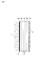
- FIG. 1 schematically shows the structure of a composite thermal insulation system according to the invention.
- the composite thermal insulation system is affixed to a wall (1) of a building.
- Layer 2 is a reinforcing mortar based on white hydrated lime and cement (Heck K + A Plus ® from BASF Wall System GmbH), to which 5% by weight of silicate aerogel powder (Nanogel ® from Cabot Corporation) have been added and which has a layer thickness of from about 5 to 10 mm.
- the thermal insulation cladding is formed by five boards (3a to 3e).
- the boards 3a to 3e each have a layer thickness of 10 mm and comprise 50% by weight of silicate aerogel, 15% by weight of inorganic filler (magnesium oxide) and 35% by weight of glass fibres.
- a process for producing the boards 3a to 3e is disclosed in US 2002094426 .
- the boards 3a to 3e are joined to one another by means of a potassium water glass binder ( 5 ), with in each case about 120 g of potassium water glass binder ( 5 ), based on the solids content thereof, being used per square metre of wall area for adhesively bonding two layers.
- a layer of a polymeric material (acrylate dispersion; not shown in Fig. 1 ) is present on both sides of the thermal insulation cladding between layers 2 and 3a and between layers 3e and 4, with about 90 g having been applied to each of the two sides of the thermal insulation cladding ( 3a to 3e ), based on the solids content of the dispersion, per square metre of wall area.
- Layer 4 is a decorative render based on silicone resin (Heck SHP ® from BASF Wall System GmbH), to which 8% by weight of silicate aerogel powder (Nanogel ® from Cabot Corporation) have been added and which has a layer thickness of about 4 mm.
Landscapes
- Engineering & Computer Science (AREA)
- Architecture (AREA)
- Physics & Mathematics (AREA)
- Civil Engineering (AREA)
- Structural Engineering (AREA)
- Acoustics & Sound (AREA)
- Electromagnetism (AREA)
- Building Environments (AREA)
- Laminated Bodies (AREA)
Claims (14)
- Isolierte Gebäudewand, umfassend ein Wärmedämmverbundsystem und eine Gebäudeaußenwand (1), wobei das Wärmedämmverbundsystem an der bauwerksfernen Seite der Gebäudewand angebracht ist, wobei das Wärmedämmverbundsystem eine mindestens zweilagige (3a bis 3c) Wärmedämmschicht umfasst, wobei mindestens zwei Lagen jeweils zwischen 25 und 95 Gew.-% Aerogel, 5 und 75 Gew.-% anorganische Fasern und 0 bis 70 Gew.-% anorganische Füllstoffe enthalten, dadurch gekennzeichnet, dass die Lagen der Wärmedämmschicht mit einem anorganischen Bindemittel (5) miteinander verbunden sind und das Wärmedämmverbundsystem einen Brennwert von weniger als 3 MJ pro Kilogramm aufweist.
- Isolierte Gebäudewand nach Anspruch 1, dadurch gekennzeichnet, dass es sich bei dem anorganischen Bindemittel um mindestens eine Komponente aus der Reihe Kaliumwasserglas, Natriumwasserglas, Zement und alkaliaktivierte Alumosilikate handelt.
- Isolierte Gebäudewand nach Anspruch 1 oder 2, dadurch gekennzeichnet, dass es sich bei dem Aerogel um mindestens eines auf Basis von Silicium, Aluminium und/oder Titan handelt.
- Isolierte Gebäudewand nach einem der Ansprüche 1 bis 3, dadurch gekennzeichnet, dass es sich bei dem anorganischen Füllstoff um Magnesiumdioxid, Titandioxid, Titancarbid, Siliciumcarbid, Eisen(III)oxid, Eisen(II)oxid, Zirkoniumsilikat, Zirkoniumoxid, Zinnoxid, Manganoxid oder deren Mischungen handelt.
- Isolierte Gebäudewand nach einem der Ansprüche 1 bis 4, dadurch gekennzeichnet, dass es sich bei den anorganischen Fasern um Glasfasern, Steinfasern, Metallfasern, Borfasern, Keramikfasern und/oder Basaltfasern handelt.
- Isolierte Gebäudewand nach einem der Ansprüche 1 bis 5, dadurch gekennzeichnet, dass die Wärmedämmschicht auf der bauwerksnahen und/oder bauwerksfernen Seite mit einem polymeren Material beschichtet ist.
- Isolierte Gebäudewand nach einem der Ansprüche 1 bis 5, dadurch gekennzeichnet, dass die Wärmedämmschicht auf der bauwerksnahen und/oder bauwerksfernen Seite mit einem anorganischen Bindemittel beschichtet ist.
- Isolierte Gebäudewand nach Anspruch 7, dadurch gekennzeichnet, dass sich an die Wärmedämmschicht auf der bauwerksfernen Seite nach außen in der folgenden Reihenfolge mindestensα) ein Gittergewebe anschließt,
sowie darauf mindestensß) eine Gewebe- oder Vliesschicht,
wobei die Wärmedämmschicht, die Schicht α) und die Schicht ß) durch das anorganische Bindemittel verbunden sind. - Isolierte Gebäudewand nach Anspruch 7 oder 8, dadurch gekennzeichnet, dass das Bindemittel die Schicht ß) zumindest teilweise penetriert.
- Isolierte Gebäudewand nach einem der Ansprüche 7 bis 9, dadurch gekennzeichnet, dass es sich bei der Schicht ß) um ein Struktur-Vlies aus Polyester, Polypropylen, Polystyrol, Glasfasern oder Mischungen daraus handelt.
- Isolierte Gebäudewand nach einem der Ansprüche 7 bis 10, dadurch gekennzeichnet, dass die mit dem anorganischen Bindemittel verbundenen Schichten α) und ß) eine Dicke von 0,5 bis 5 mm aufweisen.
- Isolierte Gebäudewand nach einem der Ansprüche 6 bis 11, dadurch gekennzeichnet, dass die Beschichtung der Wärmedämmschicht hydrophob ist und es sich um ein hydrophiles Aerogel handelt.
- Isolierte Gebäudewand nach einem der Ansprüche 1 bis 12, dadurch gekennzeichnet, dass es sich bei der Wärmedämmschicht um eine mindestens dreilagige Wärmedämmschicht handelt, wobei mindestens drei Lagen zwischen 25 und 95 Gew.-% Aerogel, 5 und 75 Gew.-% anorganische Fasern und 0 bis 70 Gew.-% anorganische Füllstoffe enthalten und jede Lage eine Schichtdicke zwischen 0,5 und 2 cm aufweist.
- Isolierte Gebäudewand nach einem der Ansprüche 1 bis 13, dadurch gekennzeichnet, dass das Wärmedämmverbundsystem weniger als 4 mechanische Befestigungspunkte pro Quadratmeter zur Verbindung mit der Gebäudewand aufweist.
Priority Applications (2)
| Application Number | Priority Date | Filing Date | Title |
|---|---|---|---|
| EP12700805.0A EP2665876B1 (de) | 2011-01-17 | 2012-01-12 | Wärmedämmverbundsystem |
| PL12700805T PL2665876T3 (pl) | 2011-01-17 | 2012-01-12 | System kompozytowej izolacji termicznej |
Applications Claiming Priority (3)
| Application Number | Priority Date | Filing Date | Title |
|---|---|---|---|
| EP11151091 | 2011-01-17 | ||
| EP12700805.0A EP2665876B1 (de) | 2011-01-17 | 2012-01-12 | Wärmedämmverbundsystem |
| PCT/EP2012/050405 WO2012098040A1 (en) | 2011-01-17 | 2012-01-12 | Composite thermal insulation system |
Publications (2)
| Publication Number | Publication Date |
|---|---|
| EP2665876A1 EP2665876A1 (de) | 2013-11-27 |
| EP2665876B1 true EP2665876B1 (de) | 2015-03-18 |
Family
ID=45524524
Family Applications (1)
| Application Number | Title | Priority Date | Filing Date |
|---|---|---|---|
| EP12700805.0A Revoked EP2665876B1 (de) | 2011-01-17 | 2012-01-12 | Wärmedämmverbundsystem |
Country Status (10)
| Country | Link |
|---|---|
| US (1) | US10344484B2 (de) |
| EP (1) | EP2665876B1 (de) |
| JP (1) | JP2014508869A (de) |
| KR (1) | KR20140006886A (de) |
| CN (1) | CN103328735B (de) |
| BR (1) | BR112013017497A2 (de) |
| CA (1) | CA2824305A1 (de) |
| PL (1) | PL2665876T3 (de) |
| RU (1) | RU2582528C2 (de) |
| WO (1) | WO2012098040A1 (de) |
Cited By (5)
| Publication number | Priority date | Publication date | Assignee | Title |
|---|---|---|---|---|
| EP3278956A1 (de) | 2016-08-03 | 2018-02-07 | Basf Se | Verfahren zur herstellung von zumindest zweilagigen platten aus einem material mit niedrigem mittlerem zelldurchmesser |
| EP3366465A1 (de) | 2017-02-28 | 2018-08-29 | Basf Se | Verfahren zur herstellung von zumindest zweilagigen platten aus mindestens einer ausgangsplatte aus einem anorganischen isolationsmaterial |
| EP3434478A1 (de) | 2017-07-28 | 2019-01-30 | Basf Se | Verfahren zur herstellung von zumindest zweilagigen platten durch verkleben aus mindestens einer ausgangsplatte aus einem anorganischen isolationsmaterial |
| RU2687816C1 (ru) * | 2018-04-23 | 2019-05-16 | Акционерное общество Научно-производственное объединение "УНИХИМТЕК" (АО НПО "УНИХИМТЕК") | Строительная плита (варианты) |
| WO2021099130A1 (en) | 2019-11-22 | 2021-05-27 | Basf Se | A thermal insulation board comprising at least one aerogel composite material for the thermal insulation of buildings |
Families Citing this family (36)
| Publication number | Priority date | Publication date | Assignee | Title |
|---|---|---|---|---|
| EP2536893A2 (de) | 2010-02-15 | 2012-12-26 | Construction Research & Technology GmbH | Externes bearbeitungssystem |
| EP2481859A1 (de) | 2011-01-17 | 2012-08-01 | Aspen Aerogels Inc. | Wärmeisolierungssystem aus Verbundaerogel |
| WO2012104067A1 (en) * | 2011-01-31 | 2012-08-09 | Rockwool International A/S | Insulation system for covering a facade of a building |
| EP2722319B1 (de) | 2012-10-16 | 2019-07-03 | STO SE & Co. KGaA | Schall- und/oder Wärmedämmung sowie Wärmedämmsystem |
| KR101454233B1 (ko) * | 2013-08-21 | 2014-10-23 | 주식회사 관평기술 | 에어로젤 블랑켓의 연속 생산방법과 생산장치 및 생산된 에어로젤 블랑켓 |
| JP6361022B2 (ja) * | 2013-09-17 | 2018-07-25 | パナソニックIpマネジメント株式会社 | 複合シート |
| EP2873656B1 (de) * | 2013-11-14 | 2019-07-31 | Imertech Sas | Verfahren zur Herstellung von Verbundstoffmaterialien mit Zement und Geopolymer mit Schichten sowie mithilfe solcher Verfahren erhaltene Produkte |
| DE102014101704A1 (de) * | 2013-12-20 | 2015-06-25 | Interbran Systems Ag | Wärmedämmputz |
| FR3030354B1 (fr) | 2014-12-17 | 2019-06-07 | Saint-Gobain Isover | Produits d'isolation thermique hautes performances |
| JP2016160553A (ja) * | 2015-03-02 | 2016-09-05 | 鉦則 藤田 | 成形体、該成形体を含む建築資材、車両、船舶、航空機及び電化製品、並びに成形体の製造方法 |
| CN106457749B (zh) * | 2015-03-30 | 2018-09-14 | 松下知识产权经营株式会社 | 一种绝热片、使用其的电子设备及绝热片的制造方法 |
| CA2993468A1 (en) | 2015-07-27 | 2017-02-02 | Basf Se | Foam as adhesive for composites for thermal insulation |
| JP6771195B2 (ja) * | 2015-08-07 | 2020-10-21 | パナソニックIpマネジメント株式会社 | 断熱材およびそれを使用した機器と断熱材の製造方法 |
| CN107098354A (zh) * | 2016-02-20 | 2017-08-29 | 金承黎 | 一种自疏水硅酸盐气凝胶材料的制备方法 |
| TWI585276B (zh) * | 2016-03-16 | 2017-06-01 | 謝騫毅 | 節能輕鋼架天花板及其天花板拼塊 |
| WO2017194726A1 (en) | 2016-05-13 | 2017-11-16 | Rockwool International A/S | Compacted body |
| JP2019168476A (ja) * | 2016-08-12 | 2019-10-03 | Agc株式会社 | 多孔質体および遮音材 |
| US10480189B2 (en) * | 2017-11-06 | 2019-11-19 | Johns Manville | Aerogel containing construction board |
| DK3749699T3 (da) | 2018-02-07 | 2022-05-23 | Basf Se | Kompositelementer af termisk isoleringsmateriale, klæbemiddel og dæklag |
| RU185206U1 (ru) * | 2018-05-23 | 2018-11-26 | Общество с ограниченной ответственностью "Всесоюзный научно-исследовательский центр транспортных технологий" (ООО "ВНИЦТТ") | Контейнер-цистерна |
| CN108673997B (zh) * | 2018-05-29 | 2021-08-17 | 安徽弘徽科技有限公司 | 一种制备大尺寸、高厚度气凝胶板的制备方法 |
| US11168485B2 (en) * | 2018-09-15 | 2021-11-09 | VBBT Corp. | Low cost emergency housing |
| CN109868909B (zh) * | 2019-03-27 | 2024-03-01 | 河北亿华保温工程有限公司 | 一种增强型抗压保温板 |
| JP7426553B2 (ja) * | 2019-05-29 | 2024-02-02 | パナソニックIpマネジメント株式会社 | 断熱シートおよびその製造方法、ならびに電子機器および電池ユニット |
| US10759697B1 (en) | 2019-06-11 | 2020-09-01 | MSB Global, Inc. | Curable formulations for structural and non-structural applications |
| JP2022536556A (ja) | 2019-08-01 | 2022-08-17 | スリーエム イノベイティブ プロパティズ カンパニー | 再充電可能な電気エネルギー貯蔵システム用の熱バリア材料 |
| CZ308884B6 (cs) | 2019-08-06 | 2021-08-04 | First Point a.s | Protipožární materiál |
| CZ309105B6 (cs) * | 2019-08-06 | 2022-02-02 | First Point a.s. | Protipožární zateplovací materiál a způsob jeho výroby |
| EP3831869B1 (de) | 2019-12-05 | 2024-03-06 | Basf Se | Polystyrolschaumstoffverbundformkörper mit geringer wärmeleitfähigkeit |
| AU2021250742A1 (en) * | 2020-03-30 | 2022-11-17 | Nexii Building Solutions Inc. | Systems and methods for adhering cladding |
| CN111893649B (zh) * | 2020-07-17 | 2022-07-26 | 3M创新有限公司 | 保暖材料、制备保暖材料的方法、以保暖材料制备的制品 |
| RU2756440C1 (ru) * | 2020-11-11 | 2021-09-30 | Общество С Ограниченной Ответственностью "Атоминпром" | Самозапирающийся вентиляционный блок, увеличивающийся в объеме при воздействии тепла элемент для самозапирающегося вентиляционного блока и огнестойкий кабельный короб, содержащий такой вентиляционный блок |
| CN112355441B (zh) * | 2020-11-18 | 2021-11-12 | 上海交通大学 | 一种减小镁稀土合金tig焊接头热影响区的熔覆剂及tig焊接方法 |
| CN112537936A (zh) * | 2020-12-28 | 2021-03-23 | 苏州启创新材料科技有限公司 | 一种气凝胶改性的高强防火砂浆材料及其制备方法 |
| KR102666096B1 (ko) * | 2022-02-21 | 2024-05-13 | 주식회사 아이원 | 단열코팅층이 연속무늬 형상으로 형성되는 실리카-에어로젤 절연시트의 연속 제조방법 |
| CN116332616B (zh) * | 2023-01-18 | 2023-10-27 | 常熟理工学院 | 由垃圾焚烧飞灰制备保温材料的方法与保温材料 |
Citations (14)
| Publication number | Priority date | Publication date | Assignee | Title |
|---|---|---|---|---|
| DE3223246A1 (de) | 1981-06-24 | 1983-01-13 | Österreichische Heraklith AG, 9702 Ferndorf, Kärnten | Mehrschicht-daemmplatte und verfahren zu ihrer herstellung |
| DE3229318A1 (de) | 1982-08-05 | 1984-02-09 | Grünzweig + Hartmann und Glasfaser AG, 6700 Ludwigshafen | Durch pressen verdichteter waermedaemmkoerper aus einem hochdispersen daemmaterial, sowie verfahren zu seiner herstellung |
| WO1996041924A1 (en) | 1995-06-12 | 1996-12-27 | Kaefer Isoleringsteknikk A/S | High temperature resistant insulating element |
| DE19533564A1 (de) | 1995-09-11 | 1997-03-13 | Hoechst Ag | Faserhaltiges Aerogel-Verbundmaterial |
| DE19702240A1 (de) | 1997-01-24 | 1998-07-30 | Hoechst Ag | Mehrschichtige Verbundmaterialien, die mindestens eine aerogelhaltige Schicht und mindestens eine weitere Schicht aufweisen, Verfahren zu ihrer Herstellung sowie ihre Verwendung |
| US5866027A (en) | 1994-08-29 | 1999-02-02 | Hoechst Aktiengesellschaft | Process for producing fiber-reinforced xerogels and their use |
| US6415573B1 (en) | 1999-09-15 | 2002-07-09 | Certainteed Corporation | Metal building insulation assembly |
| US20020094426A1 (en) | 2000-12-22 | 2002-07-18 | Aspen Aerogels, Inc. | Aerogel composite with fibrous batting |
| US20030077438A1 (en) | 1995-09-11 | 2003-04-24 | Dierk Frank | Composite aerogel material that contains fibres |
| EP1408168A1 (de) | 2002-10-11 | 2004-04-14 | Saint Gobain Isover G+H Aktiengesellschaft | Wärmedämm-Verbundsystem sowie hiermit ausgestattetes Gebäude |
| WO2006074449A2 (en) | 2005-01-07 | 2006-07-13 | Aspen Aerogels, Inc. | A thermal management system for high temperature events |
| WO2007086819A2 (en) | 2004-11-24 | 2007-08-02 | Aspen Aerogels, Inc. | High strength aerogel panels |
| WO2008110818A1 (en) | 2007-03-14 | 2008-09-18 | A. Proctor Group Ltd | Wall insulation system |
| WO2010046074A1 (en) | 2008-10-21 | 2010-04-29 | Rockwool International A/S | Facade insulation system |
Family Cites Families (17)
| Publication number | Priority date | Publication date | Assignee | Title |
|---|---|---|---|---|
| DE3274475D1 (en) * | 1981-12-10 | 1987-01-15 | Gruenzweig Hartmann Glasfaser | Heat insulating body from a highly dispersed insulating material densified by compression, and process for its production |
| DE3914850A1 (de) | 1989-05-05 | 1990-11-08 | Basf Ag | Thermisches isoliermaterial auf der basis von pigmenthaltigen kieselsaeureaerogelen |
| JP3157286B2 (ja) * | 1992-06-16 | 2001-04-16 | 日本バイリーン株式会社 | 断熱性材料 |
| US5641584A (en) * | 1992-08-11 | 1997-06-24 | E. Khashoggi Industries | Highly insulative cementitious matrices and methods for their manufacture |
| US5830548A (en) * | 1992-08-11 | 1998-11-03 | E. Khashoggi Industries, Llc | Articles of manufacture and methods for manufacturing laminate structures including inorganically filled sheets |
| US5631097A (en) * | 1992-08-11 | 1997-05-20 | E. Khashoggi Industries | Laminate insulation barriers having a cementitious structural matrix and methods for their manufacture |
| JPH08509949A (ja) * | 1993-03-08 | 1996-10-22 | イー・カショーギ・インダストリーズ | 水硬性構造マトリックスを有する断熱障壁及び製造法 |
| CN1042822C (zh) | 1993-08-31 | 1999-04-07 | Basf公司 | 疏水白炭黑 |
| DE4441567A1 (de) * | 1994-11-23 | 1996-05-30 | Hoechst Ag | Aerogelhaltiges Verbundmaterial, Verfahren zu seiner Herstellung sowie seine Verwendung |
| AU7720596A (en) * | 1995-11-09 | 1997-05-29 | Aspen Systems, Inc. | Flexible aerogel superinsulation and its manufacture |
| JPH10147664A (ja) * | 1996-11-20 | 1998-06-02 | C I Kasei Co Ltd | エアロゲル断熱パネルおよびその製造方法 |
| US20020061396A1 (en) * | 1997-11-17 | 2002-05-23 | Susan M White | Aerogel loaded tile composite material |
| JP2001171030A (ja) * | 1999-12-21 | 2001-06-26 | Tokiwa Electric Co Ltd | 不燃耐火断熱パネル、不燃耐火断熱パネル用枠材、発泡不燃断熱材及び発泡不燃断熱材の製造方法 |
| JP2001279904A (ja) * | 2000-04-03 | 2001-10-10 | Dainippon Printing Co Ltd | 断熱性壁材および断熱性壁の工法 |
| ATE365071T1 (de) * | 2002-05-15 | 2007-07-15 | Cabot Corp | Zusammensetzung auf basis von aerogel, hohlen partikeln und binder, hergestelltes dämmmaterial und herstellungsverfahren |
| CN101088954A (zh) * | 2006-06-13 | 2007-12-19 | 瞿爱花 | 憎水阻燃保温隔热材料的制备方法 |
| GB2497230A (en) * | 2010-08-06 | 2013-06-05 | Shanghai One Gold Energy Saving Technology Co Ltd | Externally insulated wall having machine anchored grid-enforced insulation board |
-
2012
- 2012-01-12 BR BR112013017497A patent/BR112013017497A2/pt active Search and Examination
- 2012-01-12 EP EP12700805.0A patent/EP2665876B1/de not_active Revoked
- 2012-01-12 CN CN201280005631.1A patent/CN103328735B/zh not_active Expired - Fee Related
- 2012-01-12 JP JP2013549772A patent/JP2014508869A/ja active Pending
- 2012-01-12 WO PCT/EP2012/050405 patent/WO2012098040A1/en active Application Filing
- 2012-01-12 CA CA2824305A patent/CA2824305A1/en not_active Abandoned
- 2012-01-12 KR KR1020137021647A patent/KR20140006886A/ko not_active Application Discontinuation
- 2012-01-12 RU RU2013138282/03A patent/RU2582528C2/ru active
- 2012-01-12 US US13/978,615 patent/US10344484B2/en not_active Expired - Fee Related
- 2012-01-12 PL PL12700805T patent/PL2665876T3/pl unknown
Patent Citations (17)
| Publication number | Priority date | Publication date | Assignee | Title |
|---|---|---|---|---|
| DE3223246A1 (de) | 1981-06-24 | 1983-01-13 | Österreichische Heraklith AG, 9702 Ferndorf, Kärnten | Mehrschicht-daemmplatte und verfahren zu ihrer herstellung |
| DE3229318A1 (de) | 1982-08-05 | 1984-02-09 | Grünzweig + Hartmann und Glasfaser AG, 6700 Ludwigshafen | Durch pressen verdichteter waermedaemmkoerper aus einem hochdispersen daemmaterial, sowie verfahren zu seiner herstellung |
| US5866027A (en) | 1994-08-29 | 1999-02-02 | Hoechst Aktiengesellschaft | Process for producing fiber-reinforced xerogels and their use |
| WO1996041924A1 (en) | 1995-06-12 | 1996-12-27 | Kaefer Isoleringsteknikk A/S | High temperature resistant insulating element |
| US20030077438A1 (en) | 1995-09-11 | 2003-04-24 | Dierk Frank | Composite aerogel material that contains fibres |
| DE19533564A1 (de) | 1995-09-11 | 1997-03-13 | Hoechst Ag | Faserhaltiges Aerogel-Verbundmaterial |
| CA2231428A1 (en) | 1995-09-11 | 1997-03-20 | Hoechst Research & Technology Deutschland Gmbh & Co. Kg | Composite aerogel material that contains fibres |
| DE19702240A1 (de) | 1997-01-24 | 1998-07-30 | Hoechst Ag | Mehrschichtige Verbundmaterialien, die mindestens eine aerogelhaltige Schicht und mindestens eine weitere Schicht aufweisen, Verfahren zu ihrer Herstellung sowie ihre Verwendung |
| US20020025427A1 (en) | 1997-01-24 | 2002-02-28 | Fritz Schwertfeger | Multilayer composite materials with at least one aerogel-containing layer and at least one other layer, process for producing the same and their use |
| US6415573B1 (en) | 1999-09-15 | 2002-07-09 | Certainteed Corporation | Metal building insulation assembly |
| US20020094426A1 (en) | 2000-12-22 | 2002-07-18 | Aspen Aerogels, Inc. | Aerogel composite with fibrous batting |
| EP1408168A1 (de) | 2002-10-11 | 2004-04-14 | Saint Gobain Isover G+H Aktiengesellschaft | Wärmedämm-Verbundsystem sowie hiermit ausgestattetes Gebäude |
| WO2007086819A2 (en) | 2004-11-24 | 2007-08-02 | Aspen Aerogels, Inc. | High strength aerogel panels |
| WO2006074449A2 (en) | 2005-01-07 | 2006-07-13 | Aspen Aerogels, Inc. | A thermal management system for high temperature events |
| US20070026214A1 (en) | 2005-01-07 | 2007-02-01 | Bullock Daniel E | Thermal management system for high temperature events |
| WO2008110818A1 (en) | 2007-03-14 | 2008-09-18 | A. Proctor Group Ltd | Wall insulation system |
| WO2010046074A1 (en) | 2008-10-21 | 2010-04-29 | Rockwool International A/S | Facade insulation system |
Non-Patent Citations (4)
| Title |
|---|
| BONDING AND COATING APPLICATIONS OF PQ® SOLUBLE SILICATES, 2006, XP055260640 |
| PQ ® POTASSIUM SILICATES INFORMATION BOOKLET, 2004, XP055260639 |
| SPACELOFT ® INSULATION INFORMATION SHEET., 2010, XP055260632 |
| SUPER CALSTIK ® DATA SHEET (NG-10804-10)., 2005, XP055260638 |
Cited By (6)
| Publication number | Priority date | Publication date | Assignee | Title |
|---|---|---|---|---|
| EP3278956A1 (de) | 2016-08-03 | 2018-02-07 | Basf Se | Verfahren zur herstellung von zumindest zweilagigen platten aus einem material mit niedrigem mittlerem zelldurchmesser |
| EP3366465A1 (de) | 2017-02-28 | 2018-08-29 | Basf Se | Verfahren zur herstellung von zumindest zweilagigen platten aus mindestens einer ausgangsplatte aus einem anorganischen isolationsmaterial |
| EP3434478A1 (de) | 2017-07-28 | 2019-01-30 | Basf Se | Verfahren zur herstellung von zumindest zweilagigen platten durch verkleben aus mindestens einer ausgangsplatte aus einem anorganischen isolationsmaterial |
| RU2687816C1 (ru) * | 2018-04-23 | 2019-05-16 | Акционерное общество Научно-производственное объединение "УНИХИМТЕК" (АО НПО "УНИХИМТЕК") | Строительная плита (варианты) |
| WO2021099130A1 (en) | 2019-11-22 | 2021-05-27 | Basf Se | A thermal insulation board comprising at least one aerogel composite material for the thermal insulation of buildings |
| EP4219142A1 (de) | 2019-11-22 | 2023-08-02 | Basf Se | Wärmedämmplatte mit mindestens einem aerogelverbundwerkstoff zur wärmeisolierung von gebäuden |
Also Published As
| Publication number | Publication date |
|---|---|
| WO2012098040A1 (en) | 2012-07-26 |
| US20140318069A1 (en) | 2014-10-30 |
| CA2824305A1 (en) | 2012-07-26 |
| US10344484B2 (en) | 2019-07-09 |
| RU2582528C2 (ru) | 2016-04-27 |
| BR112013017497A2 (pt) | 2016-09-27 |
| PL2665876T3 (pl) | 2015-08-31 |
| EP2665876A1 (de) | 2013-11-27 |
| CN103328735A (zh) | 2013-09-25 |
| RU2013138282A (ru) | 2015-02-27 |
| KR20140006886A (ko) | 2014-01-16 |
| CN103328735B (zh) | 2018-07-27 |
| JP2014508869A (ja) | 2014-04-10 |
Similar Documents
| Publication | Publication Date | Title |
|---|---|---|
| EP2665876B1 (de) | Wärmedämmverbundsystem | |
| US20130196137A1 (en) | Composite Aerogel Thermal Insulation System | |
| EP2481859A1 (de) | Wärmeisolierungssystem aus Verbundaerogel | |
| US10987910B2 (en) | Foam as adhesive for composites for thermal insulation | |
| US20220205244A1 (en) | Fiber-reinforced coated mats and mat-faced panels and methods | |
| US10060058B2 (en) | Hybrid nonwoven mats and methods | |
| US20040209074A1 (en) | Mat faced gypsum board | |
| DK3084091T3 (en) | THERMAL INSULATION PLATE | |
| CN111212946A (zh) | 矿物纤维屋顶盖板 | |
| WO2017120611A1 (en) | Fibrous mats and panels having a gypsum-based coating and methods for the manufacture thereof | |
| CA2844575C (en) | Insulation element for a flat roof or a flat inclined roof, roofing system for a flat roof or a flat inclined roof and method for producing an insulation element | |
| CN102121279B (zh) | 挤塑聚苯板外墙外保温系统及其制作工艺 | |
| CN216360856U (zh) | 一种安装方便的复合板 | |
| CN111733992A (zh) | 一种含岩棉条复合板的外墙外保温系统及施工工艺 | |
| CN110331822A (zh) | 一种屋面保温保护一体化产品及其施工方法 | |
| CN212957376U (zh) | 一种泡沫陶瓷外墙保温装饰板 |
Legal Events
| Date | Code | Title | Description |
|---|---|---|---|
| PUAI | Public reference made under article 153(3) epc to a published international application that has entered the european phase |
Free format text: ORIGINAL CODE: 0009012 |
|
| 17P | Request for examination filed |
Effective date: 20130819 |
|
| AK | Designated contracting states |
Kind code of ref document: A1 Designated state(s): AL AT BE BG CH CY CZ DE DK EE ES FI FR GB GR HR HU IE IS IT LI LT LU LV MC MK MT NL NO PL PT RO RS SE SI SK SM TR |
|
| DAX | Request for extension of the european patent (deleted) | ||
| 17Q | First examination report despatched |
Effective date: 20140512 |
|
| GRAP | Despatch of communication of intention to grant a patent |
Free format text: ORIGINAL CODE: EPIDOSNIGR1 |
|
| INTG | Intention to grant announced |
Effective date: 20141020 |
|
| GRAS | Grant fee paid |
Free format text: ORIGINAL CODE: EPIDOSNIGR3 |
|
| GRAA | (expected) grant |
Free format text: ORIGINAL CODE: 0009210 |
|
| STAA | Information on the status of an ep patent application or granted ep patent |
Free format text: STATUS: THE PATENT HAS BEEN GRANTED |
|
| AK | Designated contracting states |
Kind code of ref document: B1 Designated state(s): AL AT BE BG CH CY CZ DE DK EE ES FI FR GB GR HR HU IE IS IT LI LT LU LV MC MK MT NL NO PL PT RO RS SE SI SK SM TR |
|
| REG | Reference to a national code |
Ref country code: GB Ref legal event code: FG4D |
|
| REG | Reference to a national code |
Ref country code: CH Ref legal event code: EP |
|
| REG | Reference to a national code |
Ref country code: IE Ref legal event code: FG4D |
|
| REG | Reference to a national code |
Ref country code: AT Ref legal event code: REF Ref document number: 716681 Country of ref document: AT Kind code of ref document: T Effective date: 20150415 |
|
| REG | Reference to a national code |
Ref country code: DE Ref legal event code: R096 Ref document number: 602012005972 Country of ref document: DE Effective date: 20150430 |
|
| REG | Reference to a national code |
Ref country code: SE Ref legal event code: TRGR |
|
| REG | Reference to a national code |
Ref country code: NL Ref legal event code: T3 |
|
| PG25 | Lapsed in a contracting state [announced via postgrant information from national office to epo] |
Ref country code: LT Free format text: LAPSE BECAUSE OF FAILURE TO SUBMIT A TRANSLATION OF THE DESCRIPTION OR TO PAY THE FEE WITHIN THE PRESCRIBED TIME-LIMIT Effective date: 20150318 Ref country code: NO Free format text: LAPSE BECAUSE OF FAILURE TO SUBMIT A TRANSLATION OF THE DESCRIPTION OR TO PAY THE FEE WITHIN THE PRESCRIBED TIME-LIMIT Effective date: 20150618 Ref country code: FI Free format text: LAPSE BECAUSE OF FAILURE TO SUBMIT A TRANSLATION OF THE DESCRIPTION OR TO PAY THE FEE WITHIN THE PRESCRIBED TIME-LIMIT Effective date: 20150318 Ref country code: HR Free format text: LAPSE BECAUSE OF FAILURE TO SUBMIT A TRANSLATION OF THE DESCRIPTION OR TO PAY THE FEE WITHIN THE PRESCRIBED TIME-LIMIT Effective date: 20150318 |
|
| REG | Reference to a national code |
Ref country code: LT Ref legal event code: MG4D |
|
| PG25 | Lapsed in a contracting state [announced via postgrant information from national office to epo] |
Ref country code: RS Free format text: LAPSE BECAUSE OF FAILURE TO SUBMIT A TRANSLATION OF THE DESCRIPTION OR TO PAY THE FEE WITHIN THE PRESCRIBED TIME-LIMIT Effective date: 20150318 Ref country code: LV Free format text: LAPSE BECAUSE OF FAILURE TO SUBMIT A TRANSLATION OF THE DESCRIPTION OR TO PAY THE FEE WITHIN THE PRESCRIBED TIME-LIMIT Effective date: 20150318 Ref country code: GR Free format text: LAPSE BECAUSE OF FAILURE TO SUBMIT A TRANSLATION OF THE DESCRIPTION OR TO PAY THE FEE WITHIN THE PRESCRIBED TIME-LIMIT Effective date: 20150619 |
|
| REG | Reference to a national code |
Ref country code: PL Ref legal event code: T3 |
|
| PG25 | Lapsed in a contracting state [announced via postgrant information from national office to epo] |
Ref country code: ES Free format text: LAPSE BECAUSE OF FAILURE TO SUBMIT A TRANSLATION OF THE DESCRIPTION OR TO PAY THE FEE WITHIN THE PRESCRIBED TIME-LIMIT Effective date: 20150318 Ref country code: PT Free format text: LAPSE BECAUSE OF FAILURE TO SUBMIT A TRANSLATION OF THE DESCRIPTION OR TO PAY THE FEE WITHIN THE PRESCRIBED TIME-LIMIT Effective date: 20150720 Ref country code: SK Free format text: LAPSE BECAUSE OF FAILURE TO SUBMIT A TRANSLATION OF THE DESCRIPTION OR TO PAY THE FEE WITHIN THE PRESCRIBED TIME-LIMIT Effective date: 20150318 Ref country code: EE Free format text: LAPSE BECAUSE OF FAILURE TO SUBMIT A TRANSLATION OF THE DESCRIPTION OR TO PAY THE FEE WITHIN THE PRESCRIBED TIME-LIMIT Effective date: 20150318 Ref country code: RO Free format text: LAPSE BECAUSE OF FAILURE TO SUBMIT A TRANSLATION OF THE DESCRIPTION OR TO PAY THE FEE WITHIN THE PRESCRIBED TIME-LIMIT Effective date: 20150318 |
|
| PG25 | Lapsed in a contracting state [announced via postgrant information from national office to epo] |
Ref country code: IS Free format text: LAPSE BECAUSE OF FAILURE TO SUBMIT A TRANSLATION OF THE DESCRIPTION OR TO PAY THE FEE WITHIN THE PRESCRIBED TIME-LIMIT Effective date: 20150718 |
|
| REG | Reference to a national code |
Ref country code: DE Ref legal event code: R026 Ref document number: 602012005972 Country of ref document: DE |
|
| PLBI | Opposition filed |
Free format text: ORIGINAL CODE: 0009260 |
|
| PG25 | Lapsed in a contracting state [announced via postgrant information from national office to epo] |
Ref country code: IT Free format text: LAPSE BECAUSE OF FAILURE TO SUBMIT A TRANSLATION OF THE DESCRIPTION OR TO PAY THE FEE WITHIN THE PRESCRIBED TIME-LIMIT Effective date: 20150318 |
|
| PLAX | Notice of opposition and request to file observation + time limit sent |
Free format text: ORIGINAL CODE: EPIDOSNOBS2 |
|
| REG | Reference to a national code |
Ref country code: FR Ref legal event code: PLFP Year of fee payment: 5 |
|
| 26 | Opposition filed |
Opponent name: ROCKWOOL INTERNATIONAL A/S Effective date: 20151218 |
|
| PG25 | Lapsed in a contracting state [announced via postgrant information from national office to epo] |
Ref country code: DK Free format text: LAPSE BECAUSE OF FAILURE TO SUBMIT A TRANSLATION OF THE DESCRIPTION OR TO PAY THE FEE WITHIN THE PRESCRIBED TIME-LIMIT Effective date: 20150318 |
|
| PLAB | Opposition data, opponent's data or that of the opponent's representative modified |
Free format text: ORIGINAL CODE: 0009299OPPO |
|
| PG25 | Lapsed in a contracting state [announced via postgrant information from national office to epo] |
Ref country code: SI Free format text: LAPSE BECAUSE OF FAILURE TO SUBMIT A TRANSLATION OF THE DESCRIPTION OR TO PAY THE FEE WITHIN THE PRESCRIBED TIME-LIMIT Effective date: 20150318 |
|
| R26 | Opposition filed (corrected) |
Opponent name: ROCKWOOL INTERNATIONAL A/S Effective date: 20151218 |
|
| PLAF | Information modified related to communication of a notice of opposition and request to file observations + time limit |
Free format text: ORIGINAL CODE: EPIDOSCOBS2 |
|
| PG25 | Lapsed in a contracting state [announced via postgrant information from national office to epo] |
Ref country code: BE Free format text: LAPSE BECAUSE OF NON-PAYMENT OF DUE FEES Effective date: 20160131 |
|
| PLBB | Reply of patent proprietor to notice(s) of opposition received |
Free format text: ORIGINAL CODE: EPIDOSNOBS3 |
|
| PG25 | Lapsed in a contracting state [announced via postgrant information from national office to epo] |
Ref country code: LU Free format text: LAPSE BECAUSE OF FAILURE TO SUBMIT A TRANSLATION OF THE DESCRIPTION OR TO PAY THE FEE WITHIN THE PRESCRIBED TIME-LIMIT Effective date: 20160112 Ref country code: BE Free format text: LAPSE BECAUSE OF FAILURE TO SUBMIT A TRANSLATION OF THE DESCRIPTION OR TO PAY THE FEE WITHIN THE PRESCRIBED TIME-LIMIT Effective date: 20150318 |
|
| REG | Reference to a national code |
Ref country code: AT Ref legal event code: UEP Ref document number: 716681 Country of ref document: AT Kind code of ref document: T Effective date: 20150318 |
|
| PG25 | Lapsed in a contracting state [announced via postgrant information from national office to epo] |
Ref country code: MC Free format text: LAPSE BECAUSE OF FAILURE TO SUBMIT A TRANSLATION OF THE DESCRIPTION OR TO PAY THE FEE WITHIN THE PRESCRIBED TIME-LIMIT Effective date: 20150318 |
|
| RAP2 | Party data changed (patent owner data changed or rights of a patent transferred) |
Owner name: BASF SE |
|
| REG | Reference to a national code |
Ref country code: IE Ref legal event code: MM4A |
|
| REG | Reference to a national code |
Ref country code: FR Ref legal event code: PLFP Year of fee payment: 6 |
|
| PG25 | Lapsed in a contracting state [announced via postgrant information from national office to epo] |
Ref country code: IE Free format text: LAPSE BECAUSE OF NON-PAYMENT OF DUE FEES Effective date: 20160112 |
|
| RDAF | Communication despatched that patent is revoked |
Free format text: ORIGINAL CODE: EPIDOSNREV1 |
|
| STAA | Information on the status of an ep patent application or granted ep patent |
Free format text: STATUS: THE PATENT HAS BEEN GRANTED |
|
| PG25 | Lapsed in a contracting state [announced via postgrant information from national office to epo] |
Ref country code: MT Free format text: LAPSE BECAUSE OF FAILURE TO SUBMIT A TRANSLATION OF THE DESCRIPTION OR TO PAY THE FEE WITHIN THE PRESCRIBED TIME-LIMIT Effective date: 20150318 |
|
| APBM | Appeal reference recorded |
Free format text: ORIGINAL CODE: EPIDOSNREFNO |
|
| APBP | Date of receipt of notice of appeal recorded |
Free format text: ORIGINAL CODE: EPIDOSNNOA2O |
|
| APAH | Appeal reference modified |
Free format text: ORIGINAL CODE: EPIDOSCREFNO |
|
| APBQ | Date of receipt of statement of grounds of appeal recorded |
Free format text: ORIGINAL CODE: EPIDOSNNOA3O |
|
| REG | Reference to a national code |
Ref country code: FR Ref legal event code: PLFP Year of fee payment: 7 |
|
| PG25 | Lapsed in a contracting state [announced via postgrant information from national office to epo] |
Ref country code: HU Free format text: LAPSE BECAUSE OF FAILURE TO SUBMIT A TRANSLATION OF THE DESCRIPTION OR TO PAY THE FEE WITHIN THE PRESCRIBED TIME-LIMIT; INVALID AB INITIO Effective date: 20120112 Ref country code: SM Free format text: LAPSE BECAUSE OF FAILURE TO SUBMIT A TRANSLATION OF THE DESCRIPTION OR TO PAY THE FEE WITHIN THE PRESCRIBED TIME-LIMIT Effective date: 20150318 Ref country code: CY Free format text: LAPSE BECAUSE OF FAILURE TO SUBMIT A TRANSLATION OF THE DESCRIPTION OR TO PAY THE FEE WITHIN THE PRESCRIBED TIME-LIMIT Effective date: 20150318 |
|
| PG25 | Lapsed in a contracting state [announced via postgrant information from national office to epo] |
Ref country code: MT Free format text: LAPSE BECAUSE OF FAILURE TO SUBMIT A TRANSLATION OF THE DESCRIPTION OR TO PAY THE FEE WITHIN THE PRESCRIBED TIME-LIMIT Effective date: 20160131 Ref country code: MK Free format text: LAPSE BECAUSE OF FAILURE TO SUBMIT A TRANSLATION OF THE DESCRIPTION OR TO PAY THE FEE WITHIN THE PRESCRIBED TIME-LIMIT Effective date: 20150318 |
|
| PG25 | Lapsed in a contracting state [announced via postgrant information from national office to epo] |
Ref country code: BG Free format text: LAPSE BECAUSE OF FAILURE TO SUBMIT A TRANSLATION OF THE DESCRIPTION OR TO PAY THE FEE WITHIN THE PRESCRIBED TIME-LIMIT Effective date: 20150318 |
|
| PG25 | Lapsed in a contracting state [announced via postgrant information from national office to epo] |
Ref country code: AL Free format text: LAPSE BECAUSE OF FAILURE TO SUBMIT A TRANSLATION OF THE DESCRIPTION OR TO PAY THE FEE WITHIN THE PRESCRIBED TIME-LIMIT Effective date: 20150318 |
|
| PGFP | Annual fee paid to national office [announced via postgrant information from national office to epo] |
Ref country code: DE Payment date: 20200327 Year of fee payment: 9 |
|
| PGFP | Annual fee paid to national office [announced via postgrant information from national office to epo] |
Ref country code: PL Payment date: 20201218 Year of fee payment: 10 |
|
| REG | Reference to a national code |
Ref country code: DE Ref legal event code: R064 Ref document number: 602012005972 Country of ref document: DE Ref country code: DE Ref legal event code: R103 Ref document number: 602012005972 Country of ref document: DE |
|
| APBU | Appeal procedure closed |
Free format text: ORIGINAL CODE: EPIDOSNNOA9O |
|
| PGFP | Annual fee paid to national office [announced via postgrant information from national office to epo] |
Ref country code: CZ Payment date: 20210112 Year of fee payment: 10 Ref country code: CH Payment date: 20210122 Year of fee payment: 10 Ref country code: FR Payment date: 20210127 Year of fee payment: 10 Ref country code: NL Payment date: 20210126 Year of fee payment: 10 |
|
| RDAG | Patent revoked |
Free format text: ORIGINAL CODE: 0009271 |
|
| STAA | Information on the status of an ep patent application or granted ep patent |
Free format text: STATUS: PATENT REVOKED |
|
| REG | Reference to a national code |
Ref country code: CH Ref legal event code: PL |
|
| PGFP | Annual fee paid to national office [announced via postgrant information from national office to epo] |
Ref country code: GB Payment date: 20210128 Year of fee payment: 10 Ref country code: TR Payment date: 20210105 Year of fee payment: 10 Ref country code: SE Payment date: 20210122 Year of fee payment: 10 Ref country code: AT Payment date: 20210120 Year of fee payment: 10 |
|
| REG | Reference to a national code |
Ref country code: FI Ref legal event code: MGE |
|
| 27W | Patent revoked |
Effective date: 20210304 |
|
| GBPR | Gb: patent revoked under art. 102 of the ep convention designating the uk as contracting state |
Effective date: 20210304 |
|
| REG | Reference to a national code |
Ref country code: AT Ref legal event code: MA03 Ref document number: 716681 Country of ref document: AT Kind code of ref document: T Effective date: 20210304 |
|
| REG | Reference to a national code |
Ref country code: SE Ref legal event code: ECNC |