EP2665074B1 - Elektrochemische Zelle - Google Patents
Elektrochemische Zelle Download PDFInfo
- Publication number
- EP2665074B1 EP2665074B1 EP13167706.4A EP13167706A EP2665074B1 EP 2665074 B1 EP2665074 B1 EP 2665074B1 EP 13167706 A EP13167706 A EP 13167706A EP 2665074 B1 EP2665074 B1 EP 2665074B1
- Authority
- EP
- European Patent Office
- Prior art keywords
- separator
- inter
- electrolytic solution
- electrode
- electric double
- Prior art date
- Legal status (The legal status is an assumption and is not a legal conclusion. Google has not performed a legal analysis and makes no representation as to the accuracy of the status listed.)
- Not-in-force
Links
- 239000008151 electrolyte solution Substances 0.000 claims description 95
- 239000003365 glass fiber Substances 0.000 claims description 69
- 239000011800 void material Substances 0.000 claims description 67
- 230000006835 compression Effects 0.000 claims description 66
- 238000007906 compression Methods 0.000 claims description 66
- 238000011156 evaluation Methods 0.000 claims description 61
- OKTJSMMVPCPJKN-UHFFFAOYSA-N Carbon Chemical compound [C] OKTJSMMVPCPJKN-UHFFFAOYSA-N 0.000 claims description 33
- 239000002904 solvent Substances 0.000 claims description 32
- KMTRUDSVKNLOMY-UHFFFAOYSA-N Ethylene carbonate Chemical compound O=C1OCCO1 KMTRUDSVKNLOMY-UHFFFAOYSA-N 0.000 claims description 10
- RUOJZAUFBMNUDX-UHFFFAOYSA-N propylene carbonate Chemical compound CC1COC(=O)O1 RUOJZAUFBMNUDX-UHFFFAOYSA-N 0.000 claims description 9
- 239000012752 auxiliary agent Substances 0.000 claims description 8
- 229910002804 graphite Inorganic materials 0.000 claims description 8
- 239000010439 graphite Substances 0.000 claims description 8
- 239000010410 layer Substances 0.000 description 111
- 239000003990 capacitor Substances 0.000 description 81
- PXHVJJICTQNCMI-UHFFFAOYSA-N Nickel Chemical compound [Ni] PXHVJJICTQNCMI-UHFFFAOYSA-N 0.000 description 42
- 150000003839 salts Chemical class 0.000 description 38
- 239000000463 material Substances 0.000 description 33
- 229910052751 metal Inorganic materials 0.000 description 29
- 239000002184 metal Substances 0.000 description 29
- 239000011148 porous material Substances 0.000 description 24
- 150000005676 cyclic carbonates Chemical class 0.000 description 20
- 238000010438 heat treatment Methods 0.000 description 20
- 229910052759 nickel Inorganic materials 0.000 description 20
- 150000005678 chain carbonates Chemical class 0.000 description 19
- 239000011521 glass Substances 0.000 description 19
- 238000003466 welding Methods 0.000 description 19
- 238000007789 sealing Methods 0.000 description 18
- 239000005388 borosilicate glass Substances 0.000 description 17
- 239000003513 alkali Substances 0.000 description 16
- 229920001343 polytetrafluoroethylene Polymers 0.000 description 16
- 239000004810 polytetrafluoroethylene Substances 0.000 description 16
- 229910052799 carbon Inorganic materials 0.000 description 15
- 239000000835 fiber Substances 0.000 description 15
- 238000007747 plating Methods 0.000 description 15
- 229920002678 cellulose Polymers 0.000 description 14
- 239000001913 cellulose Substances 0.000 description 14
- 239000011230 binding agent Substances 0.000 description 13
- 230000000052 comparative effect Effects 0.000 description 13
- 239000004020 conductor Substances 0.000 description 13
- 238000002347 injection Methods 0.000 description 13
- 239000007924 injection Substances 0.000 description 13
- 239000011229 interlayer Substances 0.000 description 13
- 238000004519 manufacturing process Methods 0.000 description 13
- 238000000034 method Methods 0.000 description 13
- -1 5-azoniaspiro[4,4]nonane tetrafluoroborate Chemical compound 0.000 description 12
- 230000002093 peripheral effect Effects 0.000 description 12
- 239000002585 base Substances 0.000 description 10
- 239000006229 carbon black Substances 0.000 description 9
- 235000019241 carbon black Nutrition 0.000 description 9
- 238000005476 soldering Methods 0.000 description 9
- 238000009835 boiling Methods 0.000 description 8
- 239000011347 resin Substances 0.000 description 8
- 229920005989 resin Polymers 0.000 description 8
- 125000001931 aliphatic group Chemical group 0.000 description 7
- 230000007423 decrease Effects 0.000 description 7
- 239000010408 film Substances 0.000 description 7
- 239000011241 protective layer Substances 0.000 description 7
- 230000006870 function Effects 0.000 description 6
- 239000012535 impurity Substances 0.000 description 6
- 239000000853 adhesive Substances 0.000 description 5
- 230000001070 adhesive effect Effects 0.000 description 5
- 239000000919 ceramic Substances 0.000 description 5
- PCHJSUWPFVWCPO-UHFFFAOYSA-N gold Chemical compound [Au] PCHJSUWPFVWCPO-UHFFFAOYSA-N 0.000 description 5
- 229910052737 gold Inorganic materials 0.000 description 5
- 239000010931 gold Substances 0.000 description 5
- 238000002156 mixing Methods 0.000 description 5
- 239000002245 particle Substances 0.000 description 5
- 150000003242 quaternary ammonium salts Chemical class 0.000 description 5
- 150000003413 spiro compounds Chemical class 0.000 description 5
- XEEYBQQBJWHFJM-UHFFFAOYSA-N Iron Chemical compound [Fe] XEEYBQQBJWHFJM-UHFFFAOYSA-N 0.000 description 4
- 239000002033 PVDF binder Substances 0.000 description 4
- PNEYBMLMFCGWSK-UHFFFAOYSA-N aluminium oxide Inorganic materials [O-2].[O-2].[O-2].[Al+3].[Al+3] PNEYBMLMFCGWSK-UHFFFAOYSA-N 0.000 description 4
- 238000000354 decomposition reaction Methods 0.000 description 4
- IEJIGPNLZYLLBP-UHFFFAOYSA-N dimethyl carbonate Chemical compound COC(=O)OC IEJIGPNLZYLLBP-UHFFFAOYSA-N 0.000 description 4
- 230000005611 electricity Effects 0.000 description 4
- 230000001771 impaired effect Effects 0.000 description 4
- 238000005470 impregnation Methods 0.000 description 4
- 239000000203 mixture Substances 0.000 description 4
- 229920002981 polyvinylidene fluoride Polymers 0.000 description 4
- 238000005245 sintering Methods 0.000 description 4
- 229910000679 solder Inorganic materials 0.000 description 4
- 229920000049 Carbon (fiber) Polymers 0.000 description 3
- 229920002125 Sokalan® Polymers 0.000 description 3
- 230000004913 activation Effects 0.000 description 3
- 125000000217 alkyl group Chemical group 0.000 description 3
- 239000004917 carbon fiber Substances 0.000 description 3
- 150000001875 compounds Chemical class 0.000 description 3
- 150000002500 ions Chemical class 0.000 description 3
- 239000007788 liquid Substances 0.000 description 3
- 150000002739 metals Chemical class 0.000 description 3
- 238000000465 moulding Methods 0.000 description 3
- 229920005569 poly(vinylidene fluoride-co-hexafluoropropylene) Polymers 0.000 description 3
- 230000009467 reduction Effects 0.000 description 3
- 239000000243 solution Substances 0.000 description 3
- 239000000126 substance Substances 0.000 description 3
- WFKWXMTUELFFGS-UHFFFAOYSA-N tungsten Chemical compound [W] WFKWXMTUELFFGS-UHFFFAOYSA-N 0.000 description 3
- 229910052721 tungsten Inorganic materials 0.000 description 3
- 239000010937 tungsten Substances 0.000 description 3
- XLYOFNOQVPJJNP-UHFFFAOYSA-N water Substances O XLYOFNOQVPJJNP-UHFFFAOYSA-N 0.000 description 3
- BVKZGUZCCUSVTD-UHFFFAOYSA-L Carbonate Chemical compound [O-]C([O-])=O BVKZGUZCCUSVTD-UHFFFAOYSA-L 0.000 description 2
- 229920002134 Carboxymethyl cellulose Polymers 0.000 description 2
- VYZAMTAEIAYCRO-UHFFFAOYSA-N Chromium Chemical compound [Cr] VYZAMTAEIAYCRO-UHFFFAOYSA-N 0.000 description 2
- RYGMFSIKBFXOCR-UHFFFAOYSA-N Copper Chemical compound [Cu] RYGMFSIKBFXOCR-UHFFFAOYSA-N 0.000 description 2
- YCKRFDGAMUMZLT-UHFFFAOYSA-N Fluorine atom Chemical compound [F] YCKRFDGAMUMZLT-UHFFFAOYSA-N 0.000 description 2
- 239000004372 Polyvinyl alcohol Substances 0.000 description 2
- VYPSYNLAJGMNEJ-UHFFFAOYSA-N Silicium dioxide Chemical compound O=[Si]=O VYPSYNLAJGMNEJ-UHFFFAOYSA-N 0.000 description 2
- BQCADISMDOOEFD-UHFFFAOYSA-N Silver Chemical compound [Ag] BQCADISMDOOEFD-UHFFFAOYSA-N 0.000 description 2
- HCHKCACWOHOZIP-UHFFFAOYSA-N Zinc Chemical compound [Zn] HCHKCACWOHOZIP-UHFFFAOYSA-N 0.000 description 2
- NIXOWILDQLNWCW-UHFFFAOYSA-N acrylic acid group Chemical group C(C=C)(=O)O NIXOWILDQLNWCW-UHFFFAOYSA-N 0.000 description 2
- 239000013543 active substance Substances 0.000 description 2
- 229910052782 aluminium Inorganic materials 0.000 description 2
- XAGFODPZIPBFFR-UHFFFAOYSA-N aluminium Chemical compound [Al] XAGFODPZIPBFFR-UHFFFAOYSA-N 0.000 description 2
- 150000001450 anions Chemical class 0.000 description 2
- 229910052793 cadmium Inorganic materials 0.000 description 2
- BDOSMKKIYDKNTQ-UHFFFAOYSA-N cadmium atom Chemical compound [Cd] BDOSMKKIYDKNTQ-UHFFFAOYSA-N 0.000 description 2
- 239000002041 carbon nanotube Substances 0.000 description 2
- 229910021393 carbon nanotube Inorganic materials 0.000 description 2
- 238000003763 carbonization Methods 0.000 description 2
- 150000001768 cations Chemical class 0.000 description 2
- 239000003795 chemical substances by application Substances 0.000 description 2
- 229910052804 chromium Inorganic materials 0.000 description 2
- 239000011651 chromium Substances 0.000 description 2
- 239000011231 conductive filler Substances 0.000 description 2
- 229910052802 copper Inorganic materials 0.000 description 2
- 239000010949 copper Substances 0.000 description 2
- 230000007797 corrosion Effects 0.000 description 2
- 238000005260 corrosion Methods 0.000 description 2
- 238000009826 distribution Methods 0.000 description 2
- 230000000694 effects Effects 0.000 description 2
- 239000007772 electrode material Substances 0.000 description 2
- JBTWLSYIZRCDFO-UHFFFAOYSA-N ethyl methyl carbonate Chemical compound CCOC(=O)OC JBTWLSYIZRCDFO-UHFFFAOYSA-N 0.000 description 2
- 239000012467 final product Substances 0.000 description 2
- 239000011737 fluorine Substances 0.000 description 2
- 229910052731 fluorine Inorganic materials 0.000 description 2
- 239000006232 furnace black Substances 0.000 description 2
- 229910052742 iron Inorganic materials 0.000 description 2
- 238000005304 joining Methods 0.000 description 2
- WPBNNNQJVZRUHP-UHFFFAOYSA-L manganese(2+);methyl n-[[2-(methoxycarbonylcarbamothioylamino)phenyl]carbamothioyl]carbamate;n-[2-(sulfidocarbothioylamino)ethyl]carbamodithioate Chemical compound [Mn+2].[S-]C(=S)NCCNC([S-])=S.COC(=O)NC(=S)NC1=CC=CC=C1NC(=S)NC(=O)OC WPBNNNQJVZRUHP-UHFFFAOYSA-L 0.000 description 2
- 238000002844 melting Methods 0.000 description 2
- 230000008018 melting Effects 0.000 description 2
- VNWKTOKETHGBQD-UHFFFAOYSA-N methane Chemical compound C VNWKTOKETHGBQD-UHFFFAOYSA-N 0.000 description 2
- BKIMMITUMNQMOS-UHFFFAOYSA-N nonane Chemical compound CCCCCCCCC BKIMMITUMNQMOS-UHFFFAOYSA-N 0.000 description 2
- 239000004745 nonwoven fabric Substances 0.000 description 2
- 239000011368 organic material Substances 0.000 description 2
- 230000000149 penetrating effect Effects 0.000 description 2
- 150000004714 phosphonium salts Chemical group 0.000 description 2
- 239000004584 polyacrylic acid Substances 0.000 description 2
- 229920000642 polymer Polymers 0.000 description 2
- 229920002451 polyvinyl alcohol Polymers 0.000 description 2
- 239000000047 product Substances 0.000 description 2
- 229910052709 silver Inorganic materials 0.000 description 2
- 239000004332 silver Substances 0.000 description 2
- 238000003860 storage Methods 0.000 description 2
- CBXCPBUEXACCNR-UHFFFAOYSA-N tetraethylammonium Chemical compound CC[N+](CC)(CC)CC CBXCPBUEXACCNR-UHFFFAOYSA-N 0.000 description 2
- 229920001187 thermosetting polymer Polymers 0.000 description 2
- 239000010409 thin film Substances 0.000 description 2
- SEACXNRNJAXIBM-UHFFFAOYSA-N triethyl(methyl)azanium Chemical compound CC[N+](C)(CC)CC SEACXNRNJAXIBM-UHFFFAOYSA-N 0.000 description 2
- 230000008016 vaporization Effects 0.000 description 2
- 229910052725 zinc Inorganic materials 0.000 description 2
- 239000011701 zinc Substances 0.000 description 2
- SMZOUWXMTYCWNB-UHFFFAOYSA-N 2-(2-methoxy-5-methylphenyl)ethanamine Chemical compound COC1=CC=C(C)C=C1CCN SMZOUWXMTYCWNB-UHFFFAOYSA-N 0.000 description 1
- 239000004925 Acrylic resin Substances 0.000 description 1
- 229910000531 Co alloy Inorganic materials 0.000 description 1
- 235000013162 Cocos nucifera Nutrition 0.000 description 1
- 244000060011 Cocos nucifera Species 0.000 description 1
- 229910000640 Fe alloy Inorganic materials 0.000 description 1
- 229910001030 Iron–nickel alloy Inorganic materials 0.000 description 1
- 229910000990 Ni alloy Inorganic materials 0.000 description 1
- ISWSIDIOOBJBQZ-UHFFFAOYSA-N Phenol Chemical compound OC1=CC=CC=C1 ISWSIDIOOBJBQZ-UHFFFAOYSA-N 0.000 description 1
- 239000004696 Poly ether ether ketone Substances 0.000 description 1
- 239000004642 Polyimide Substances 0.000 description 1
- 239000004734 Polyphenylene sulfide Substances 0.000 description 1
- 229920000297 Rayon Polymers 0.000 description 1
- 241000872198 Serjania polyphylla Species 0.000 description 1
- 238000010521 absorption reaction Methods 0.000 description 1
- 239000006230 acetylene black Substances 0.000 description 1
- 230000009471 action Effects 0.000 description 1
- 150000001334 alicyclic compounds Chemical class 0.000 description 1
- QVGXLLKOCUKJST-UHFFFAOYSA-N atomic oxygen Chemical group [O] QVGXLLKOCUKJST-UHFFFAOYSA-N 0.000 description 1
- 239000001768 carboxy methyl cellulose Substances 0.000 description 1
- 235000010948 carboxy methyl cellulose Nutrition 0.000 description 1
- 239000008112 carboxymethyl-cellulose Substances 0.000 description 1
- 230000008859 change Effects 0.000 description 1
- 239000006231 channel black Substances 0.000 description 1
- 239000011248 coating agent Substances 0.000 description 1
- 238000000576 coating method Methods 0.000 description 1
- 239000010941 cobalt Substances 0.000 description 1
- GUTLYIVDDKVIGB-UHFFFAOYSA-N cobalt atom Chemical compound [Co] GUTLYIVDDKVIGB-UHFFFAOYSA-N 0.000 description 1
- 239000000571 coke Substances 0.000 description 1
- 238000001816 cooling Methods 0.000 description 1
- 229910052593 corundum Inorganic materials 0.000 description 1
- 238000004132 cross linking Methods 0.000 description 1
- 239000002180 crystalline carbon material Substances 0.000 description 1
- 230000003247 decreasing effect Effects 0.000 description 1
- 230000006866 deterioration Effects 0.000 description 1
- 238000004090 dissolution Methods 0.000 description 1
- 239000000428 dust Substances 0.000 description 1
- 230000004927 fusion Effects 0.000 description 1
- 239000007789 gas Substances 0.000 description 1
- 238000003306 harvesting Methods 0.000 description 1
- 239000003779 heat-resistant material Substances 0.000 description 1
- 230000010220 ion permeability Effects 0.000 description 1
- 238000010030 laminating Methods 0.000 description 1
- 239000005355 lead glass Substances 0.000 description 1
- 230000014759 maintenance of location Effects 0.000 description 1
- 230000015654 memory Effects 0.000 description 1
- 230000004048 modification Effects 0.000 description 1
- 238000012986 modification Methods 0.000 description 1
- 239000002116 nanohorn Substances 0.000 description 1
- 230000003647 oxidation Effects 0.000 description 1
- 238000007254 oxidation reaction Methods 0.000 description 1
- 229910052760 oxygen Inorganic materials 0.000 description 1
- 239000001301 oxygen Substances 0.000 description 1
- 239000005011 phenolic resin Substances 0.000 description 1
- 239000004033 plastic Substances 0.000 description 1
- 229920003023 plastic Polymers 0.000 description 1
- 229920001495 poly(sodium acrylate) polymer Polymers 0.000 description 1
- 229920001690 polydopamine Polymers 0.000 description 1
- 229920002530 polyetherether ketone Polymers 0.000 description 1
- 229920001721 polyimide Polymers 0.000 description 1
- 229920000069 polyphenylene sulfide Polymers 0.000 description 1
- 239000000843 powder Substances 0.000 description 1
- 239000002964 rayon Substances 0.000 description 1
- 238000005096 rolling process Methods 0.000 description 1
- 229920006395 saturated elastomer Polymers 0.000 description 1
- 239000005361 soda-lime glass Substances 0.000 description 1
- NNMHYFLPFNGQFZ-UHFFFAOYSA-M sodium polyacrylate Chemical compound [Na+].[O-]C(=O)C=C NNMHYFLPFNGQFZ-UHFFFAOYSA-M 0.000 description 1
- 239000007787 solid Substances 0.000 description 1
- 238000003892 spreading Methods 0.000 description 1
- 230000007480 spreading Effects 0.000 description 1
- 239000007858 starting material Substances 0.000 description 1
- 238000003756 stirring Methods 0.000 description 1
- 229920003048 styrene butadiene rubber Polymers 0.000 description 1
- 239000000758 substrate Substances 0.000 description 1
- HXJUTPCZVOIRIF-UHFFFAOYSA-N sulfolane Chemical compound O=S1(=O)CCCC1 HXJUTPCZVOIRIF-UHFFFAOYSA-N 0.000 description 1
- 150000003457 sulfones Chemical class 0.000 description 1
- 239000013589 supplement Substances 0.000 description 1
- 239000003115 supporting electrolyte Substances 0.000 description 1
- 150000005687 symmetric chain carbonates Chemical class 0.000 description 1
- 239000006234 thermal black Substances 0.000 description 1
- 238000007740 vapor deposition Methods 0.000 description 1
- 238000009834 vaporization Methods 0.000 description 1
- KMIOJWCYOHBUJS-HAKPAVFJSA-N vorolanib Chemical compound C1N(C(=O)N(C)C)CC[C@@H]1NC(=O)C1=C(C)NC(\C=C/2C3=CC(F)=CC=C3NC\2=O)=C1C KMIOJWCYOHBUJS-HAKPAVFJSA-N 0.000 description 1
- 229910001845 yogo sapphire Inorganic materials 0.000 description 1
Images


Classifications
-
- H—ELECTRICITY
- H01—ELECTRIC ELEMENTS
- H01G—CAPACITORS; CAPACITORS, RECTIFIERS, DETECTORS, SWITCHING DEVICES, LIGHT-SENSITIVE OR TEMPERATURE-SENSITIVE DEVICES OF THE ELECTROLYTIC TYPE
- H01G11/00—Hybrid capacitors, i.e. capacitors having different positive and negative electrodes; Electric double-layer [EDL] capacitors; Processes for the manufacture thereof or of parts thereof
- H01G11/22—Electrodes
-
- H—ELECTRICITY
- H01—ELECTRIC ELEMENTS
- H01G—CAPACITORS; CAPACITORS, RECTIFIERS, DETECTORS, SWITCHING DEVICES, LIGHT-SENSITIVE OR TEMPERATURE-SENSITIVE DEVICES OF THE ELECTROLYTIC TYPE
- H01G11/00—Hybrid capacitors, i.e. capacitors having different positive and negative electrodes; Electric double-layer [EDL] capacitors; Processes for the manufacture thereof or of parts thereof
- H01G11/52—Separators
-
- H—ELECTRICITY
- H01—ELECTRIC ELEMENTS
- H01G—CAPACITORS; CAPACITORS, RECTIFIERS, DETECTORS, SWITCHING DEVICES, LIGHT-SENSITIVE OR TEMPERATURE-SENSITIVE DEVICES OF THE ELECTROLYTIC TYPE
- H01G9/00—Electrolytic capacitors, rectifiers, detectors, switching devices, light-sensitive or temperature-sensitive devices; Processes of their manufacture
- H01G9/004—Details
- H01G9/02—Diaphragms; Separators
-
- H—ELECTRICITY
- H01—ELECTRIC ELEMENTS
- H01G—CAPACITORS; CAPACITORS, RECTIFIERS, DETECTORS, SWITCHING DEVICES, LIGHT-SENSITIVE OR TEMPERATURE-SENSITIVE DEVICES OF THE ELECTROLYTIC TYPE
- H01G9/00—Electrolytic capacitors, rectifiers, detectors, switching devices, light-sensitive or temperature-sensitive devices; Processes of their manufacture
- H01G9/004—Details
- H01G9/04—Electrodes or formation of dielectric layers thereon
-
- H—ELECTRICITY
- H01—ELECTRIC ELEMENTS
- H01G—CAPACITORS; CAPACITORS, RECTIFIERS, DETECTORS, SWITCHING DEVICES, LIGHT-SENSITIVE OR TEMPERATURE-SENSITIVE DEVICES OF THE ELECTROLYTIC TYPE
- H01G9/00—Electrolytic capacitors, rectifiers, detectors, switching devices, light-sensitive or temperature-sensitive devices; Processes of their manufacture
- H01G9/145—Liquid electrolytic capacitors
-
- H—ELECTRICITY
- H01—ELECTRIC ELEMENTS
- H01M—PROCESSES OR MEANS, e.g. BATTERIES, FOR THE DIRECT CONVERSION OF CHEMICAL ENERGY INTO ELECTRICAL ENERGY
- H01M4/00—Electrodes
- H01M4/02—Electrodes composed of, or comprising, active material
- H01M4/62—Selection of inactive substances as ingredients for active masses, e.g. binders, fillers
- H01M4/624—Electric conductive fillers
- H01M4/625—Carbon or graphite
-
- H—ELECTRICITY
- H01—ELECTRIC ELEMENTS
- H01M—PROCESSES OR MEANS, e.g. BATTERIES, FOR THE DIRECT CONVERSION OF CHEMICAL ENERGY INTO ELECTRICAL ENERGY
- H01M50/00—Constructional details or processes of manufacture of the non-active parts of electrochemical cells other than fuel cells, e.g. hybrid cells
- H01M50/40—Separators; Membranes; Diaphragms; Spacing elements inside cells
- H01M50/409—Separators, membranes or diaphragms characterised by the material
- H01M50/431—Inorganic material
- H01M50/434—Ceramics
- H01M50/437—Glass
-
- H—ELECTRICITY
- H01—ELECTRIC ELEMENTS
- H01M—PROCESSES OR MEANS, e.g. BATTERIES, FOR THE DIRECT CONVERSION OF CHEMICAL ENERGY INTO ELECTRICAL ENERGY
- H01M50/00—Constructional details or processes of manufacture of the non-active parts of electrochemical cells other than fuel cells, e.g. hybrid cells
- H01M50/40—Separators; Membranes; Diaphragms; Spacing elements inside cells
- H01M50/409—Separators, membranes or diaphragms characterised by the material
- H01M50/44—Fibrous material
-
- Y—GENERAL TAGGING OF NEW TECHNOLOGICAL DEVELOPMENTS; GENERAL TAGGING OF CROSS-SECTIONAL TECHNOLOGIES SPANNING OVER SEVERAL SECTIONS OF THE IPC; TECHNICAL SUBJECTS COVERED BY FORMER USPC CROSS-REFERENCE ART COLLECTIONS [XRACs] AND DIGESTS
- Y02—TECHNOLOGIES OR APPLICATIONS FOR MITIGATION OR ADAPTATION AGAINST CLIMATE CHANGE
- Y02E—REDUCTION OF GREENHOUSE GAS [GHG] EMISSIONS, RELATED TO ENERGY GENERATION, TRANSMISSION OR DISTRIBUTION
- Y02E60/00—Enabling technologies; Technologies with a potential or indirect contribution to GHG emissions mitigation
- Y02E60/10—Energy storage using batteries
-
- Y—GENERAL TAGGING OF NEW TECHNOLOGICAL DEVELOPMENTS; GENERAL TAGGING OF CROSS-SECTIONAL TECHNOLOGIES SPANNING OVER SEVERAL SECTIONS OF THE IPC; TECHNICAL SUBJECTS COVERED BY FORMER USPC CROSS-REFERENCE ART COLLECTIONS [XRACs] AND DIGESTS
- Y02—TECHNOLOGIES OR APPLICATIONS FOR MITIGATION OR ADAPTATION AGAINST CLIMATE CHANGE
- Y02E—REDUCTION OF GREENHOUSE GAS [GHG] EMISSIONS, RELATED TO ENERGY GENERATION, TRANSMISSION OR DISTRIBUTION
- Y02E60/00—Enabling technologies; Technologies with a potential or indirect contribution to GHG emissions mitigation
- Y02E60/13—Energy storage using capacitors
-
- Y—GENERAL TAGGING OF NEW TECHNOLOGICAL DEVELOPMENTS; GENERAL TAGGING OF CROSS-SECTIONAL TECHNOLOGIES SPANNING OVER SEVERAL SECTIONS OF THE IPC; TECHNICAL SUBJECTS COVERED BY FORMER USPC CROSS-REFERENCE ART COLLECTIONS [XRACs] AND DIGESTS
- Y02—TECHNOLOGIES OR APPLICATIONS FOR MITIGATION OR ADAPTATION AGAINST CLIMATE CHANGE
- Y02P—CLIMATE CHANGE MITIGATION TECHNOLOGIES IN THE PRODUCTION OR PROCESSING OF GOODS
- Y02P70/00—Climate change mitigation technologies in the production process for final industrial or consumer products
- Y02P70/50—Manufacturing or production processes characterised by the final manufactured product
Definitions
- the present invention relates to an electrochemical cell such as an electric double layer capacitor and an ion capacitor.
- An electric double layer capacitor that is an electricity storage device includes a pair of polarizable electrodes, a separator interposed between the pair of polarizable electrodes, and an electrolytic solution with which the pair of polarizable electrodes and the separator are impregnated, in a housing container sealed with a lid body and a container main body.
- an electric double layer capacitor is utilized as a backup power source for memories, a backup power source for clock functions, and the like.
- an electric double layer capacitor of a button type having a disc shape is widely used.
- an electric double layer capacitor of a chip type having a rectangular shape has also been proposed (see, for example, JP-A-2001-216952 and JP-A-2012-64922 ).
- US2012/0044614 discloses an electrolytic solution for an electrolytic double layer capacitor capable of providing an electric double layer capacitor having stable quality, an electric double-layer capacitor using the electrolytic solution, and a manufacturing method for the electric double layer capacitor.
- the electrolytic solution includes a supporting electrolyte, sulfolane, and a linear sulfone.
- an electric double layer capacitor to be mounted on an energy harvesting instrument is required to achieve efficient electricity storage of a minute voltage.
- an electric double layer capacitor to be mounted on a handheld instrument such as smartphones is required to have performances of instantaneous electricity generation and instantaneous discharge for the purpose of assisting a current of a main battery. Accordingly, such an electric double layer capacitor is strongly required to achieve, in addition to downsizing and thinning, a reduction of the resistance value.
- the present invention according to claim 1, has been made, and an object thereof is to provide an electrochemical cell with a low resistance value.
- the electrochemical cell of the present invention is an electrochemical cell as defined in claim 1.
- the thinner the thickness L2 of the inter-electrode part the smaller the distance between the pair of electrodes is, and therefore, the resistance value of the inter-electrode part becomes small.
- the larger the inter-electrode part void ratio Re the more easily the electrolytic solution flows into the inter-electrode part, whereby the ionic conductivity is enhanced, and therefore, the resistance value of the inter-electrode part becomes small.
- the separator evaluation index le which is defined by L2/Re not more than 1.0 ( ⁇ m/%), it is possible to sufficiently reduce the resistance value of the electrochemical cell (for example, not more than 50 ⁇ ).
- the thickness L2 of the inter-electrode part becomes small. According to this, the separator evaluation index le becomes small, so that the resistance value of the electrochemical cell can be reduced. In that case, the pair of electrodes is expanded to compress the separator within the housing container, and therefore, it is possible to simply manufacture an electrochemical cell including the compressed separator within the housing container.
- the separator is made of a laminate of glass fiber.
- the separator By forming the separator by a laminate of glass fiber having a thin fiber diameter, a large void is formed in the inside of the separator, and therefore, the inter-electrode part void ratio Re becomes large. According to this, the separator evaluation index le becomes small, so that the resistance value of the inter-electrode part can be reduced.
- the electrolytic solution contains, as a solvent, propylene carbonate and ethylene carbonate.
- the electrolytic solution contains propylene carbonate and ethylene carbonate each having a high dielectric constant (conductivity), and therefore, it is possible to significantly reduce the resistance value of the electrochemical cell.
- the larger the inter-electrode part void ratio Re the more easily the electrolytic solution flows into the inter-electrode part, whereby the ionic conductivity is enhanced, and therefore, the resistance value of the inter-electrode part becomes small.
- the separator evaluation index le which is defined by L2/Re to not more than 1.0 ( ⁇ m/%), it is possible to sufficiently reduce the resistance value of the inter-electrode part.
- An electric double layer capacitor 1 of a first embodiment shown in FIG. 1 is of a so-called chip type and is a substantially rectangular parallelepiped having a length of from 2 to 3 mm, a width of from 2 to 3 mm, and a height of from 0.2 to 1 mm.
- the electric double layer capacitor 1 includes an electrochemical device 15 in the inside of a housing container 2.
- the electrochemical device 15 is one in which a pair of polarizable electrodes 40 composed of a negative electrode side electrode 42 and a positive electrode side electrode 44 is disposed opposite to each other via a separator 46, and an electrolytic solution 50 is housed. Then, the polarizable electrodes 40 and the separator 46 are impregnated with the electrolytic solution 50 housed in the housing container 2.
- the housing container 2 includes a container main body 20 having a square cylindrical shape with a closed bottom, a lid body 10 that is a flat sealing plate for covering an opening of the container main body 20, and a seal ring 30 placed on the periphery of the opening of the container main body 20, and the lid body 10 and the container main body 20 are sealed via the seal ring 30.
- a thickness of a wall of the housing container 2 is not particularly limited, it is, for example, from 0.15 to 0.25 mm.
- the container main body 20 includes a bottom wall part 21 which includes a flat base 22 having a substantially rectangular shape in a planar view and an interlayer 26 formed on one surface of the base 22; and a side wall part 24 having a square cylindrical shape vertically arranged on the periphery of the bottom wall part 21.
- a conductive protective layer 27 penetrating through the interlayer 26 is provided in the substantial center of the interlayer 26.
- the negative electrode side electrode 42 is electrically connected to the lid body 10, and for example, it is preferable that the negative electrode side electrode 42 is allowed to adhere to the lid body 10 with a negative electrode collector 43 composed of a conductive resin adhesive.
- the positive electrode side electrode 44 is electrically connected to the protective layer 27 with a positive electrode collector 45 similar to the negative electrode collector 43.
- a thermosetting resin for the conductive resin adhesive binder
- the heat resistance of an adhesive part can be enhanced.
- the conductivity can be enhanced.
- the external bottom surface and the external side surface of the container main body 20 are provided with a first external terminal 60 and a second external terminal 70.
- the first external terminal 60 is connected to a first metal layer 62 provided between the soldering material 32 and the side wall part 24. According to this, the first external terminal 60 is electrically connected to the negative electrode side electrode 42 via the first metal layer 62, the soldering material 32, the seal ring 30, the lid body 10, and the negative electrode collector 43.
- the second external terminal 70 is connected to a second metal layer 72 which is provided between the base 22 and the interlayer 26 and connected to the protective layer 27. According to this, the second external terminal 70 is electrically connected to the positive electrode side electrode 44 via the second metal layer 72, the protection layer 27, and the positive electrode collector 45.
- An electrolytic solution 50 is a solution of a supporting salt dissolved in a nonaqueous solvent.
- the nonaqueous solvent contains a cyclic carbonate as a prime solvent.
- At least propylene carbonate (PC) and ethylene carbonate (EC) are contained as the cyclic carbonate.
- PC and EC each having a high dielectric constant (conductivity) are contained, the resistance value of the electrolytic solution can be reduced.
- PC and EC are contained in the electrolytic solution, and therefore, it is desirable to make a voltage to be impressed to not more than 3.1 V, an aspect of which, however, varies with active carbon to be used as an electrode material.
- the nonaqueous solvent contains, as an auxiliary solvent, one or more kinds of a symmetric or asymmetric chain carbonate.
- a symmetric chain carbonate with a short aliphatic chain is preferable.
- MP about 40 °C
- a chain carbonate having a symmetric shape for example, dimethyl carbonate (DMC)
- DMC dimethyl carbonate
- the supporting salt or nonaqueous solvent of the electrolytic solution 50 is decomposed.
- the decomposition product is vaporized to form air bubbles, and the electrolytic solution 50 remaining in the separator 46 between the negative electrode side electrode 42 and the positive electrode side electrode 44 (between the electrodes) is extruded by the thus formed air bubbles, whereby its amount decreases.
- the amount of the electrolytic solution 50 conspicuously decreases in the vicinity of the surface of the separator 46.
- the decomposed component produced following the decomposition of the electrolytic solution 50 in the vicinity of the surface of each of the negative electrode side electrode 42 and the positive electrode side electrode 44 forms a film especially on the electrode in the vicinity of the surface of the separator 46, and the thus formed film accelerates a further increase of the resistance and an increase of the overvoltage, thereby lowering the discharge capacity within a short period of time.
- the void ratio can be controlled by, for example, adjusting an injection amount of the electrolytic solution 50 in an injection step as described later, or blending the electrolytic solution 50 with a solvent having a low boiling point (lower than 200 °C) or water in advance and vaporizing the solvent having a low boiling point in a preheating step as described later.
- Void ratio % by volume Volume of void in housing container / Capacity of housing container ⁇ 100
- the "Capacity of housing container” means a volume of a space surrounded by the lid body 10 and the container main body 20.
- the "Volume of void of housing container” means a volume of a void 3 produced in the inside of the housing container 2.
- the propylene carbonate (PC) is a substance represented by the following formula (a) and has a boiling point (bp) of 240 °C.
- the ethylene carbonate (EC) is a substance represented by the following formula (b) and has a boiling point (bp) of 260 °C.
- a content of the cyclic carbonate in the nonaqueous solvent can be determined taking into account a heating condition in the preheating step or sealing step in the manufacture of the electric double layer capacitor 1, a heating condition at the time of use, or the like, and for example, it is preferably from 25 to 90 % by mass, more preferably from 50 to 80 % by mass, and still more preferably from 55 to 70 % by mass.
- a heating condition in the preheating step or sealing step in the manufacture of the electric double layer capacitor 1 a heating condition at the time of use, or the like, and for example, it is preferably from 25 to 90 % by mass, more preferably from 50 to 80 % by mass, and still more preferably from 55 to 70 % by mass.
- the injection amount of the electrolytic solution 50 is varied, and the remaining amount of the electrolytic solution 50 becomes instable, so that the electric double layer capacitor 1 with a stable quality is hardly obtained.
- the content of the cyclic carbonate exceeds 90 % by mass, the amount of the supporting salt in the nonaqueous solvent becomes insufficient, so that there is a concern that it may be impossible to sufficiently ensure the discharge capacity of the electric double layer capacitor 1.
- the content of the cyclic carbonate exceeds 90 % by mass, the content of the chain carbonate or the supporting salt becomes insufficient, so that there may be the case where it becomes difficult to ensure the discharge capacity under a low-temperature environment (not higher than -20 °C).
- the symmetric or asymmetric chain carbonate as referred to herein is a carbonate having a structure in which a total of two linear or branched aliphatic alkyl groups are bonded to oxygen (O) of the carbonate.
- the two alkyl groups constituting the chain carbonate may be the same as or different from each other.
- the chain carbonate can be determined taking into account requirements for the electrolytic solution 50, such as heat resistance.
- dimethyl carbonate (DMC) represented by the following formula (c) and ethyl methyl carbonate (EMC) represented by the following formula (d) are preferable.
- dimethyl carbonate which in view of the fact that the alkyl groups are made symmetric, has a melting point of room temperature or higher and is convenient for handling is preferable.
- DMC dimethyl carbonate
- EMC ethyl methyl carbonate
- a total sum amount of the cyclic carbonate and the chain carbonate in the nonaqueous solvent can be determined taking into account a heating condition in the preheating step or sealing step in the manufacture of the electric double layer capacitor 1, a heating condition at the time of use, or the like, and for example, it is preferably from 40 to 90 % by mass, more preferably from 65 to 90 % by mass, and still more preferably from 75 to 85 % by mass.
- a heating condition in the preheating step or sealing step in the manufacture of the electric double layer capacitor 1 a heating condition at the time of use, or the like, and for example, it is preferably from 40 to 90 % by mass, more preferably from 65 to 90 % by mass, and still more preferably from 75 to 85 % by mass.
- Examples of the supporting salt include quaternary ammonium salts and quaternary phosphonium salts.
- Examples of the quaternary ammonium salt include compounds having only an aliphatic chain, alicyclic compounds having an aliphatic chain and an aliphatic ring, and spiro compounds having only an aliphatic ring.
- the spiro compound is a compound having a structure in which two rings share one atom of a tetrahedron structure.
- Examples of the spiro compound include 5-azoniaspiro[4,4]nonane tetrafluoroborate (spiro-(1,1')-bipyrrolidinium: SBP-BF 4 ) represented by the following formula (3), 6-azoniaspiro[5,5]undecane tetrafluoroborate represented by the following formula (4), 3-azoniaspiro[2,6]nonane tetrafluoroborate represented by the following formula (5), and 4-azoniaspiro[3,5]nonane tetrafluoroborate represented by the following formula (6).
- examples of the quaternary phosphonium salt include 5-phosphonylspiro[4,4]nonane tetrafluoroborate represented by the following formula (7).
- the supporting salt is preferably a quaternary ammonium salt, more preferably a spiro compound, and still more preferably 5-azoniaspiro[4,4]nonane tetrafluoroborate.
- the spiro compound of a quaternary ammonium salt has a high electric conductivity, and hence, it is able to increase the discharge capacity.
- a content of the supporting salt in the electrolytic solution 50 can be determined taking into account the type of the supporting salt, or the like.
- the content of the supporting salt in the electrolytic solution 50 which is used in an injection step as described later, is preferably from 1.0 to 3.6 mol/dm 3 , and more preferably from 1.5 to 3.6 mol/dm 3 .
- the content of the supporting salt is less than 1.0 mol/dm 3 , in the case of charging at a voltage exceeding 2.9 V, the deterioration of the electrolytic solution 50 becomes conspicuous, and the discharge capacity is liable to be lowered within a short period of time.
- the nonaqueous solvent and the supporting salt evaporate in the preheating step or sealing step as described later.
- the cyclic carbonate, the chain carbonate, and the arbitrary solvent in the nonaqueous solvent easily evaporate as compared with the supporting salt, and therefore, the content of the supporting salt in the electrolytic solution 50 of the electric double layer capacitor 1 as a final product is increased.
- the content of the supporting salt in the electrolytic solution 50 to be filled in the injection step may be adjusted taking into account the type of the nonaqueous solvent or the like in such a manner that the content of the supporting salt in the electrolytic solution 50 of the electric double layer capacitor 1 as a final product is preferably from 1.0 to 3.6 mol/dm 3 , and more preferably from 1.5 to 3.6 mol/dm 3 .
- the supporting salt when a voltage is impressed (applied) to the electric double layer capacitor 1, the supporting salt is decomposed and reduced. Accordingly, in an application of impressing a high voltage, the supporting salt may be in an excessive (supersaturated) state.
- the supporting salt in the electrolytic solution 50 sealed in the housing container 2 may be in a state where after going through the supersaturated state, it is temporally deposited without being dissolved. On that occasion, in the electrolytic solution 50, the solubility of the supporting salt changes due to the supporting salt in a supersaturated state and the decomposition product.
- the supporting salt is dissolved again, and the concentration of the supporting salt is increased, whereby a high discharge capacity under a low-temperature environment can be ensured.
- the supporting salt corresponding to the decomposed part thereof can be supplemented by bringing the supporting salt into a supersaturated state.
- the electrolytic solution 50 can be prepared by, for example, mixing a cyclic carbonate, a chain carbonate, and optionally, an arbitrary solvent to form a nonaqueous solvent, adding a supporting salt to the nonaqueous solvent, and dissolving them by stirring.
- Examples of the negative electrode side electrode 42 include those prepared by carrying out pressure rolling or press molding of an active carbon powder obtained by subjecting a saw dust, a coconut shell, a pitch, a coke, or an organic material such as a phenol resin to an activation treatment with steam or an alkali, etc. alone or in combination, together with a binder.
- examples thereof include those prepared by subjecting phenol based, rayon based, acrylic, or pitch based fibers, or the like to a non-fusion and carbonization activation treatment to obtain active carbon or active carbon fibers, followed by forming into a felt, fiber, paper, or sintered body form.
- a density of the negative electrode side electrode 42 is not particularly limited, and it is preferably from 0.1 to 0.9 g/cm 3 , and more preferably from 0.40 to 0.75 g/cm 3 .
- the density of the negative electrode side electrode 42 is less than 0.1 g/cm 3 , not only the energy density of the negative electrode side electrode 42 is lowered, but there is a concern that at the time of expansion of the negative electrode side electrode 42 by impregnation with the electric solution 50, the distance between the electrode particles spreads to increase the electrical resistance.
- the active carbon that is an active substance of the negative electrode side electrode 42 those having various pore distributions and surface states are obtained depending upon the starting material, the carbonization treatment method, or the activation condition.
- a specific surface area of the active carbon which is used as the active substance of the negative electrode side electrode 42 is preferably 1,000 m 2 /g or more, more preferably 1,700 m 2 /g or more, and still more preferably 2,400 m 2 /g or more. So far as the specific surface area of the active carbon is 1,000 m 2 /g or more, a sufficient electrostatic capacity is obtained.
- a pore volume of the active carbon is preferably 0.4 cm 3 /g or more, and more preferably 0.7 cm 3 /g or more. So far as the pore volume of the active carbon is 0.4 cm 3 /g or more, a sufficient electrostatic capacity is obtained.
- a value expressed by "(number of pores with a pore radius of less than 1 nm)/(number of all pores)" which is a proportion of pores with a pore radius of less than 1 nm occupying in all of the pores (proportion of fine pores), is preferably not more than 75 %, more preferably not more than 50 %, and still more preferably not more than 30 %. This is because so far as the foregoing value is not more than 75 %, a sufficient electrostatic capacity is obtained.
- a value expressed by "(number of pores with a pore radius of from 1 to 3 nm)/(number of all pores)" which is a proportion of pores with a pore radius of from 1 to 3 nm occupying in all of the pores (proportion of medium-sized pores), is preferably 20 % or more, more preferably 50 % or more, and still more preferably 70 % or more. So far as the foregoing value is 20 % or more, a sufficient electrostatic capacity is obtained. So far as the foregoing value is 70 % or more, an anti-deterioration performance against continuous impression with a voltage of 2.3 V or more is more enhanced due to a combination with the electrolytic solution 50 containing a cyclic carbonate.
- binder conventionally known substances can be used.
- examples thereof include polytetrafluoroethylene (PTFE), polyvinylidene fluoride (PVDF), a polyvinylidene fluoride-hexafluoropropylene copolymer (PVDF-HFP), a styrene-butadiene rubber (SBR), a polyacrylic acid based polymer, carboxymethyl cellulose, and a polyimide.
- PTFE polytetrafluoroethylene
- PVDF polyvinylidene fluoride
- PVDF-HFP polyvinylidene fluoride-hexafluoropropylene copolymer
- SBR styrene-butadiene rubber
- fluorine based polymers are preferable, and PTFE and PVDF are the most preferable. Any one of PTFE, PVDF, and PVDF-HFP can also be used solely, or plural kinds thereof can be mixed in an arbitrary proportion and simultaneously used.
- a content of the binder in the negative electrode side electrode 42 is, for example, preferably from 2 to 14 % by mass, and it is more preferably from 4 to 12 % by mass from the viewpoints of an enhancement in durability and an enhancement in handling properties during the manufacture.
- a blending ratio of the fluorine based binder is preferably not more than 8 % by mass.
- a conductivity imparting agent can be added to the negative electrode side electrode 42.
- the conductivity imparting agent include amorphous carbons such as carbon blacks, e.g., furnace black, channel black, acetylene black, and thermal black, crystalline carbonaceous materials such as a carbon fiber (CF), a carbon nanohorn (CNH), a carbon nanotube (CNT), and a graphite powder, and powders of a metal having high corrosion resistance, such as SUS and Ti.
- a blending ratio of the active carbon and the conductive auxiliary agent is preferably not more than 90/4, more preferably not more than 70/24, and especially preferably not more than 50/44.
- the blending ratio of the binder is made low, it is necessary to apply a sufficient shear to PTFE as the binder to stretch PTFE in a yarn form and then to entangle it with particles of the active carbon. Accordingly, as the conductive auxiliary agent, carbon blacks capable of keeping a structure of carbon black even at the time of applying a sufficient shear, and especially oil furnace black having a hollow shell structure is desirable.
- the conductive auxiliary agent it is desirable to use a mixture of graphite with high crystallinity and carbon black with low crystallinity.
- the graphite has a large particle diameter, its own electron conductivity is high.
- the carbon black is low in the electron conductivity as compared with the graphite, its particle diameter is small.
- the carbon black having a small particle diameter comes into gaps of the electrode material, whereby the resistance value of the whole of the electrode can be decreased. Then, the resistance value can be optimized by using a mixture of graphite and carbon black as the conductive auxiliary agent. It is desirable to add the graphite in an amount of 20 % by weight or more and not more than 60 % by weight.
- Examples of the positive electrode side electrode 44 include the same materials as those of the negative electrode side electrode 42.
- the negative electrode side electrode 42 and the positive electrode side electrode 44 may be the same as or different from each other, and the positive electrode side electrode 44 can be determined taking into account the type of the supporting salt or the like.
- the positive electrode side electrode 44 can be determined taking into account the type of the supporting salt or the like.
- a surface area ratio expressed by (surface area of the negative electrode side electrode 42)/(surface area of the positive electrode side electrode 44) is preferably in the range of from 0.8 to 1.2, and it is properly adjusted.
- Examples of the material of separator 46 include a laminate of glass fiber (glass fiber laminate), which is made of, for example, borosilicate glass, alkali glass, quartz glass, lead glass, soda lime silica glass, or alkali-free glass; a nonwoven fabric made of a resin such as polyphenylene sulfide and polyetheretherketone, or cellulose; and a microporous film of polytetrafluoroethylene (PTFE).
- a glass fiber laminate is preferable; a borosilicate glass, alkali glass, or quartz glass fiber laminate is more preferable; and an alkali glass fiber laminate is still more preferable.
- the glass fiber laminate has an excellent mechanical strength and also has a high ion permeability, and therefore, it is possible to contrive to enhance the discharge capacity by reducing the internal resistance.
- the glass fiber laminate may also be one in which not only glass fibers are bonded to each other with a binder and integrated as a whole, but voids are formed.
- the glass fiber laminate may also be one prepared by molding a mixture of fibers made of glass (glass fibers) with a binder in an arbitrary shape and subjecting the resultant to a heat treatment of heating at, for example, from 25 to 250 °C.
- the separator 46 does not contain impurities as far as possible.
- the separator 46 does not contain metals such as cadmium, manganese, zinc, copper, nickel, chromium, and iron.
- a content of each of the metals in the separator 46 is preferably less than 1 ⁇ g/g for cadmium, less than 0.5 ⁇ g/g for manganese, less than 5 ⁇ g/g for zinc, less than 4 ⁇ g/g for copper, less than 1 ⁇ g/g for nickel, less than 1 ⁇ g/g for chromium, and less than 25 ⁇ g/g for iron, respectively.
- the glass fiber constituting the glass fiber laminate may be a mixture of glass fibers having a fiber diameter of more than 0.5 ⁇ m and not more than 1.0 ⁇ m and glass fibers having a fiber diameter of not more than 0.5 ⁇ m. In that case, it is preferable that the glass fiber contains 80 % by mass or more of glass fibers having a fiber diameter of not more than 0.5 ⁇ m. When the glass fiber contains 80 % by mass or more of glass fibers having a fiber diameter of not more than 0.5 ⁇ m, not only the electrolytic solution 50 is more easily infiltrated into the separator 46, but the resistance between the electrodes can be more reduced.
- a mass of the glass fiber laminate per unit area (hereinafter referred to as "unit mass”) is preferably not more than 24 g/m 2 , and more preferably not more than 16 g/m 2 .
- a thickness of the inter-electrode part 46a after compression is preferably from 5 to 40 ⁇ m, and more preferably 10 to 20 ⁇ m. When the thickness of the inter-electrode part 46a is less than 5 ⁇ m, there is a concern that a function to separate the negative electrode side electrode 42 and the positive electrode side electrode 44 from each other is impaired.
- the thickness of the inter-electrode part 46a exceeds 40 ⁇ m, the resistance between the electrodes becomes large, and a current-voltage drop (IR loss) becomes large, and hence, there is a concern that the performances of instantaneous electricity charge and instantaneous discharge are lowered.
- a compression ratio L2/L1 which is a ratio of a thickness L2 after compression to a thickness L1 before compression in the inter-electrode part 46a of the separator 46, is 0.15 or more and not more than 0.6.
- the compression ratio L2/L1 exceeds 0.6, the distance between the electrodes becomes separated, and the electrical resistance increases.
- the compression ratio L2/L1 is less than 0.15, the liquid retention amount of the electrolytic solution is lowered, and the ionic conductivity is lowered. As a result, the electrical resistance increases.
- the ratio L2/L1 By allowing the ratio L2/L1 to fall within the range of 0.15 or more and not more than 0.6, the ionic conductivity between the electrodes is ensured, whereby the electrical resistance can be lowered.
- the void ratio (inter-electrode part void ratio Re) in the inter-electrode part 46a of the separator 46 is preferably from 10 to 90 % by volume, more preferably from 45 to 90 % by volume, and still more preferably from 50 to 90 % by volume.
- the inter-electrode part void ratio Re falls within the foregoing range, the amount of the electrolytic solution 50 in the inter-electrode part 46a is sufficient, and the discharge capacity is hardly lowered. Also, the electrolytic solution 50 is properly supplemented into the inter-electrode part 46a by means of a capillarity phenomenon, and the discharge capacity is easily kept for a long period of time.
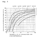
- FIG. 3 is a graph showing a relation between a thickness L2 of an inter-electrode part after compression and a void ratio Re of an inter-electrode part with respect to Separators A to E having a different thickness L1 before compression from each other and the like.
- the inter-electrode part void ratio Re is corresponding to an impregnation ratio of the electrolytic solution. Therefore, the larger the inter-electrode part void ratio Re, the more easily the electrolytic solution flows into the inter-electrode part 46a, whereby the ionic conductivity is enhanced, and the resistance value of the inter-electrode part 46a becomes small. Then, the smaller the thickness L2 of the inter-electrode part 46a after compression, and the larger the inter-electrode part void ratio Re, the smaller the separator evaluation index le is.
- the separator evaluation index le of the electric double layer capacitor of the related art exceeds 1.0 ( ⁇ m/%), as represented by Comparative Examples 1 and 2 of Table 1 as described later. Then, the resistance value of the electric double layer capacitor of the related art is 50 ⁇ or more, and a reduction of the resistance value is desired.
- the separator evaluation index le is preferably 0.33 ( ⁇ m/%) or more.
- the lid body 10 is a plate made of a conductive metal, such as KovarTM (alloy of iron, nickel, and cobalt) and for a nickel-iron alloy containing about 50 % by mass of nickel, and subjected to nickel plating.
- a conductive metal such as KovarTM (alloy of iron, nickel, and cobalt)
- nickel-iron alloy containing about 50 % by mass of nickel, and subjected to nickel plating.
- the lid body 10 and the seal ring 30 are preferably made of materials having the same linear expansion coefficient for the purpose of preventing a sealed part from becoming fragile due to an expansion rate of the material at the time of joining and a stress at the time of shrinkage to be caused by cooling after joining.
- the seal ring 30 and the container main body 20 are preferably selected from materials having proximate linear expansion coefficients for the purpose of preventing the container main body 20 from being broken by a residual stress by heat.
- alumina (Al 2 O 3 ) which is used as a principal component of the housing container 2 has a representative value (400 °C) of a linear expansion coefficient of 7.1 ⁇ 10 -6 K -1
- KovarTM which is used as a principal component of the lid body 10 or the seal ring 30 has a representative value of a linear expansion coefficient of 4.9 ⁇ 10 -6 K -1 .
- soldering material 32 examples include conventionally known soldering materials such as a gold solder, and a silver solder.
- Examples of the base material 22 include heat-resistant materials having insulating properties, such as a ceramic, glass, a plastic, and alumina.
- the side wall part 24 is made of the same material as that of the base 22.
- the side wall part 24 is obtained by, for example, sintering a green sheet.
- the interlayer 26 is made of the same material as that of the base 22.
- the interlayer 26 is, for example, made of a green sheet just as in the case of the side wall part 24.
- the interlayer 26 can also be formed by providing the second metal layer 72 on the base 22 and coating a green sheet of, for example, ceramic, glass, or alumina to the second metal layer 72 so as to cover the second metal layer 72, followed by sintering.
- the protective layer 27 is made of a conductive metal such as aluminum, tungsten, gold, and silver, a conductive resin containing carbon as a conductive filler, or the like. Of these, aluminum and a conductive resin are preferable.
- the protective layer 27 can be formed in such a manner that at the time of forming the interlayer 26, an arbitrary number of conductive metals, conductive resins, or the like are formed at an arbitrary position and then sintered.
- the first external terminal 60 is a plate or thin film made of a conductive metal such as nickel and gold, and it is formed by, for example, subjecting the container main body 20 to conductor printing and sintering. It is preferable that a deposited layer of nickel, gold, a solder, or the like is formed on the surface of the first external terminal 60 such that it can be welded on the substrate. This deposited layer can be formed by a gas phase method such as plating and vapor deposition.
- a configuration of the second external terminal 70 is the same as that of the first external terminal 60.
- the first metal layer 62 is a plate or thin film made of a conductive metal such as tungsten, nickel, gold, and silver, and it is formed by, for example, printing the metal on a green sheet, followed by sintering. Above of all, it is preferable that the first metal layer 62 is made of tungsten.
- a configuration of the second metal layer 72 is the same as that of the first metal layer 62.
- the container main body 20 provided with the interlayer 26, the protective layer 27, the first external terminal 60, the first metal layer 62, the second external terminal 70, and the second metal layer 72 is prepared.
- the seal ring 30 is joined to the periphery of the opening of the container main body 20, i.e., the upper end surface 23 of the side wall part 24 by the soldering material 32.
- nickel plating is performed so as to cover the seal ring 30, the soldering material 32, and the upper end surface 23.
- the nickel plating may be performed by, for example, electrolytic nickel plating or electroless nickel plating.
- the separator 46 may be heated before injecting the electrolytic solution 50 (separator-heating treatment).
- the separator 46 adsorbed water or a variety of organic materials on the surface of the glass fiber laminate can be removed by means of oxidation or volatilization, and the separator 46 can be rapidly impregnated with a larger amount of the electrolytic solution 50.
- the negative electrode side electrode 42 is allowed to adhere onto one surface of the lid body 10 by the negative electrode collector 43, and the lid body 10 is mounted on the seal ring 30 so as to allow the negative electrode side electrode 42 to come into contact with the separator 46.
- the negative electrode side electrode 42 is mounted so as to come into contact with the separator 46, and the lid body 10 on which the negative electrode collector 43 is previously formed is then mounted on the seal ring 30 (electrode-disposing step).
- Each of the positive electrode side electrode 44 and the negative electrode side electrode 42 absorbs the electrolytic solution and expands.
- the pair of the electrodes 44 and 42 as expanded gives a compression load to the both surfaces of the separator 46. According to this, the inter-electrode part 46a of the separator 46 is compressed, whereby its thickness is reduced.
- the peripheral part 46b of the separator 46 which has protruded from the pair of the electrodes 44 and 42 keeps substantially the same thickness as that before compression.
- the lid body 10 and the seal ring 30 are welded while being partially melted to form an unsealed body.
- a method of partially welding the lid body 10 and the seal ring 30 include a method of partially welding the nickel plating of the lid body 10 and the nickel plating covering the seal ring 30 by means of resistance welding, laser welding, hot welding, or the like. Above all, resistance welding is preferable. It is meant by the terms “partially welding" that the lid body 10 and the seal ring 30 are welded by means of spot welding or the like in which welding portions are placed at intervals.
- the unsealed body obtained by partially welding the lid body 10 and the seal ring 30 is heated at 200 °C or higher and lower than 900 °C (preheating step).
- impurities such as moisture can be removed from the electrolytic solution 50, or a part of the nonaqueous solvent can be evaporated to increase the concentration of the supporting salt in the electrolytic solution 50.
- the viscosity of the electrolytic solution 50 is reduced by heating.
- the polarizable electrodes 40 or the separator 46 can be sufficiently impregnated with the electrolytic solution 50.
- a method of heating in the preheating step is not particularly limited, and examples thereof include a method of allowing a current to pass through the lid body 10 and a heating method by irradiation with a laser or warm air. Of these, a method of allowing a current to pass through the lid body 10 is preferable.
- the temperature of the electrolytic solution 50 increases within in a short period of time, whereby the impurities in the electrolytic solution 50 can be efficiently removed.
- the method of allowing a current to pass through the lid body 10 can also serve as partial welding between the lid body 10 and the seal ring 30 as described above, and therefore, it is possible to contrive to enhance the production efficiency of the electric double layer capacitor 1.
- the electrolytic solution 50 is exposed to the melting point (from 800 to 1,455 °C) of the nickel plating.
- the electrolytic solution 50 contains a cyclic carbonate having a relatively high boiling point, and hence, an appropriate amount of the electrolytic solution 50 remains within the housing container 2 without easily causing volatilization of the whole amount of the electrolytic solution 50.
- the whole amount of the electrolytic solution 50 is not easily vaporized, and hence, it is possible to protect the housing container 2 from being broken during the sealing step.
- the electric double layer capacitor according to the present embodiment was configured such that when the thickness of the inter-electrode part 46a of the separator 46 is designated as L2 ( ⁇ m), and the inter-electrode void ratio is designated as Re (%), the separator evaluation index le defined as L2/Re is not more than 1.0 ( ⁇ m/%).
- the larger the inter-electrode part void ratio Re the more easily the electrolytic solution flows into the inter-electrode part 46a, whereby the ionic conductivity is enhanced, and therefore, the resistance value of the inter-electrode part 46a becomes small.
- the separator evaluation index le which is defined by L2/Re not more than 1.0 ( ⁇ m/%), it is possible to reduce the resistance value of the inter-electrode part 46a to not more than 50 ⁇ .
- the separator evaluation index le it is possible to reduce the resistance value of the inter-electrode part 46a to not more than 40 ⁇ .
- the separator By forming the separator by a laminate of glass fiber having a thin fiber diameter, a large void is formed in the inside of the separator, and therefore, the inter-electrode part void ratio Re becomes large.
- the thickness L2 of the inter-electrode part 46a becomes small. According to these, the separator evaluation index le becomes small, so that the resistance value of the inter-electrode part can be reduced.
- the electric double layer capacitor 1 is of a chip type, it should not be construed that the present invention is limited to this type, but it may be of a button type.
- the second metal layer 72 is provided between the interlayer 26 and the base 22.
- the second metal layer 72 may be provided on the interlayer 26.
- the second metal layer 72 does not come into contact with the electrolytic solution 50 by, for example, providing the second metal layer 72 between the interlayer 26 and the base 22.
- the preheating step is provided. However, it should not be construed that the present invention is limited thereto, and the preheating step may be omitted. However, from the viewpoints of removing impurities and the like in the electrolytic solution and keeping the high discharge capacity for a long period of time, it is preferable to provide the preheating step.
- the electric double layer capacitor is of a chip type including the container main body having a square cylindrical shape with a closed bottom end and the lid body having a flat plate shape, in which the external terminals are mounted on the container main body.
- the present invention is limited thereto.
- an electric double layer capacitor of a chip type shown in FIG. 2 may also be used.
- An electric double layer capacitor 100 according to a second embodiment shown in FIG. 2 is one in which a pair of polarizable electrodes 40 composed of a negative electrode side electrode 42 and a positive electrode side electrode 44 is disposed opposite to each other via a separator 46 in a housing container 102, and an electrolytic solution 50 is housed. Then, the polarizable electrodes 40 and the separator 46 are impregnated with the electrolytic solution 50 housed within the housing container 102.
- the container main body 110 includes a top wall part 112 having a flat plate of a substantially rectangular shape in a planar view, a side wall part 114 having a rectangular tube shape, which extends downward from the periphery of the top wall part 112, and a flange part 116 which is formed on the lower end of the side wall part 114 and extends in the direction extending away from the axial line of the side wall part 114.
- the lid body 120 has a two-layer structure formed of an upper layer 122 and a lower layer 124. On substantially the center of the surface of the upper layer 122, a second conductor part 145 having a substantially rectangular shape in a planar view is formed. In the vicinity of the periphery of the upper layer 122, a first conductor part 132 having a hollow square shape is formed. A first external terminal 160 and a second external terminal 170 are formed on the lower surface 124 from the lateral side to the bottom. A lead-out conductor part 172 is formed between the upper layer 122 and the lower layer 124 and extends from substantially the center of the lid body 120 to the periphery thereof. The first external terminal 160 is connected to the first conductor part 132. The second external terminal 170 is connected to a lead-out conductor part 172. The lead-out conductor part 172 is connected to the second conductor part 145 by a via conductor part 174 penetrating through the upper layer 122.
- a configuration of the first external terminal 160 is the same as the configuration of the first external terminal 60, and a configuration of the second external terminal 170 is the same as the configuration of the second external terminal 70.
- a material of the first conductor part 132 is the same as the material of the first metal layer 62, and a material of the second conductor part 145 is the same as the material of the positive electrode collector 45.
- a material of the lead-out conductor part 172 is the same as the material of the second metal layer 72.
- a material of the via conductor part 174 is the same as the material of the protective layer 27.
- Examples of the electric double layer capacitor of a chip type device like the electric double layer capacitor 100 include an electrochemical device described in JP-A-2010-141026 .
- active carbon (specific surface area: 1,900 m 2 /g, pore volume: 0.85 cm 3 /g, proportion of fine pores: 4 %, proportion of medium-sized pores: 95 %, and number average pore diameter: 12 ⁇ m (measured by a laser mode)) was rolled into a sheet of 0.25 mm ⁇ 0.05 mm in thickness and then cut into pieces having a size of 1.7 mm ⁇ 1.0 mm. The resulting pieces were used as a positive electrode side electrode and a negative electrode side electrode, respectively. The negative electrode side electrode was allowed to adhere to a lid body, which was prepared by subjecting a KovarTM flat plate to electrolytic nickel plating, with a conductive adhesive.
- the housing container was sealed by means of seam welding according to the resistance welding method, thereby obtaining an electric double layer capacitor.
- the obtained electric double layer capacitor had a void ratio of 25 % by volume and a surface area ratio of 1.0.
- the separator was formed of a glass fiber laminate of an alkali glass.
- the separator was compressed from the thickness L1 before compression of 100 ⁇ m to the thickness L2 after compression of 23 ⁇ m.
- the inter-electrode void ratio Re after compression is 68.7 %, and the separator evaluation index le is 0.337.
- the thus fabricated electric double layer capacitor was measured in terms of a resistance value.
- the resistance value was measured in terms of a value at an alternating current of 1 kHz by using an LCR meter, KC-594B Model, manufactured by KDK Corporation and using an R function. As shown in Table 1, the measured resistance value was 22 Q.
- the measured resistance value was 25 ⁇ .
- a separator was formed of a glass fiber laminate of an alkali glass.
- a density of the glass fiber is 2.345 g/cc, and a unit mass of the glass fiber laminate is 23.7 g/m 2 .
- the separator was compressed from the thickness L1 before compression of 150 ⁇ m to the thickness L2 after compression of 32 ⁇ m.
- the inter-electrode void ratio Re after compression is 68.7 %, and the separator evaluation index le is 0.470.
- An electric double layer capacitor was fabricated in the same manner as that in Example 1, except for the foregoing.
- the measured resistance value was 26 ⁇ .
- a separator was formed of a glass fiber laminate of an alkali glass.
- a density of the glass fiber is 2.349 g/cc, and a unit mass of the glass fiber laminate is 26.0 g/m 2 .
- the separator was compressed from the thickness L1 before compression of 150 ⁇ m to the thickness L2 after compression of 35 ⁇ m.
- the inter-electrode void ratio Re after compression is 68.8 %, and the separator evaluation index le is 0.515.
- An electric double layer capacitor was fabricated in the same manner as that in Example 1, except for the foregoing.
- the measured resistance value was 26 ⁇ .
- a separator was formed of a glass fiber laminate of an alkali glass.
- a density of the glass fiber is 2.349 g/cc, and a unit mass of the glass fiber laminate is 31.0 g/m 2 .
- the separator was compressed from the thickness L1 before compression of 200 ⁇ m to the thickness L2 after compression of 42 ⁇ m.
- the inter-electrode void ratio Re after compression is 68.8 %, and the separator evaluation index le is 0.615.
- An electric double layer capacitor was fabricated in the same manner as that in Example 1, except for the foregoing.
- the measured resistance value was 31 ⁇ .
- the separator was formed of a glass fiber laminator of an alkali glass, and the separator evaluation index le was made to be not more than 1.0 ⁇ m/%. Therefore, the resistance value could be reduced to not more than 50 ⁇ .
- the separator evaluation index le was made to be not more than 0.62 ⁇ m/%, and therefore, the resistance value was not more than 40 ⁇ . Thus, Examples 4 and 5 were decided to be "preferred".
- the separator evaluation index le was made to not more than 0.50 ⁇ m/%, and therefore, the resistance value was not more than 30 ⁇ . Thus, Examples 2 and 3 were decided to be "more preferred”.
- the separator evaluation index le was made to not more than 0.35 ⁇ m/%, and therefore, the resistance value was not more than 25 ⁇ . Thus, Example 1 was decided to be "especially preferred”.
- a separator was formed of a glass fiber laminate of a borosilicate glass.
- a density of the glass fiber is 2.3 g/cc, and a unit mass of the glass fiber laminate is 29.3 g/m 2 .
- the separator was compressed from the thickness L1 before compression of 41 ⁇ m to the thickness L2 after compression of 20 ⁇ m.
- the inter-electrode void ratio Re after compression is 57.4 %, and the separator evaluation index le is 0.356.
- An electric double layer capacitor was fabricated in the same manner as that in Example 1, except for the foregoing.
- the measured resistance value was 20 ⁇ .
- a separator was formed of a glass fiber laminate of a borosilicate glass.
- a density of the glass fiber is 2.3 g/cc, and a unit mass of the glass fiber laminate is 28.2 g/m 2 .
- the separator was compressed from the thickness L1 before compression of 51 ⁇ m to the thickness L2 after compression of 26 ⁇ m.
- the inter-electrode void ratio Re after compression is 51.9 %, and the separator evaluation index le is 0.492.
- An electric double layer capacitor was fabricated in the same manner as that in Example 1, except for the foregoing.
- the measured resistance value was 27 ⁇ .
- a separator was formed of a glass fiber laminate of a borosilicate glass.
- a density of the glass fiber is 2.3 g/cc, and a unit mass of the glass fiber laminate is 24.0 g/m 2 .
- the separator was compressed from the thickness L1 before compression of 83 ⁇ m to the thickness L2 after compression of 41 ⁇ m.
- the inter-electrode void ratio Re after compression is 69.3 %, and the separator evaluation index le is 0.598.
- An electric double layer capacitor was fabricated in the same manner as that in Example 1, except for the foregoing.
- the measured resistance value was 22 ⁇ .
- the measured resistance value was 23 ⁇ .
- the separator was formed of a glass fiber laminator of a borosilicate glass, and the separator evaluation index le was made to be not more than 1.0 ⁇ m/%. Therefore, the resistance value could be reduced to not more than 50 ⁇ .
- the separator evaluation index le was made to be not more than 0.62 ⁇ m/%, and therefore, the resistance value was not more than 40 ⁇ . Thus, Examples 8 and 9 were decided to be "preferred".
- the separator evaluation index le was made to be not more than 0.50 ⁇ m/%, and therefore, the resistance value was not more than 30 ⁇ . Thus, Example 7 was decided to be "more preferred”.
- the separator evaluation index le was made to not more than 0.35 ⁇ m/%, and therefore, the resistance value was not more than 25 ⁇ . Thus, Example 6 was decided to be "especially preferred”.
- a separator was formed of a cellulose laminate.
- a density of the cellulose is 1.4 g/cc, and a unit mass of the cellulose laminate is 14.9 g/m 2 .
- the separator was not compressed, keeping the thickness 19.8 ⁇ m as it is.
- the inter-electrode void ratio Re is 46.2 %, and the separator evaluation index le is 0.428.
- An electric double layer capacitor was fabricated in the same manner as that in Example 1, except for the foregoing.
- the measured resistance value was 23 ⁇ .
- a separator was formed of a cellulose laminate.
- a density of the cellulose is 1.4 g/cc, and a unit mass of the cellulose laminate is 18.3 g/m 2 .
- the separator is not compressed, keeping the thickness 25.4 ⁇ m as it is.
- the inter-electrode void ratio Re is 48.4 %, and the separator evaluation index le is 0.524.
- An electric double layer capacitor was fabricated in the same manner as that in Example 1, except for the foregoing.
- a separator was formed of a cellulose laminate.
- a density of the cellulose is 1.4 g/cc, and a unit mass of the cellulose laminate is 21.3 g/m 2 .
- the separator is not compressed, keeping the thickness 30.7 ⁇ m as it is.
- the inter-electrode void ratio Re is 50.4 %, and the separator evaluation index le is 0.609.
- An electric double layer capacitor was fabricated in the same manner as that in Example 1, except for the foregoing.
- the measured resistance value was 38 ⁇ .
- a separator was formed of a microporous film of polytetrafluoroethylene (PTFE). The separator is not compressed, keeping the thickness 25.0 ⁇ m as it is. The inter-electrode void ratio Re is 61.0 %, and the separator evaluation index le is 0.410. An electric double layer capacitor was fabricated in the same manner as that in Example 1, except for the foregoing.
- PTFE polytetrafluoroethylene
- the measured resistance value was 25 ⁇ .
- a separator was formed of a microporous film of polytetrafluoroethylene (PTFE). The separator is not compressed, keeping the thickness 50.0 ⁇ m as it is. The inter-electrode void ratio Re is 65.0 %, and the separator evaluation index le is 0.769.
- An electric double layer capacitor was fabricated in the same manner as that in Example 1, except for the foregoing.
- the measured resistance value was 48 ⁇ .
- a separator was formed of a glass fiber laminate of a borosilicate glass.
- a density of the glass fiber is 2.3 g/cc, and a unit mass of the glass fiber laminate is 46.0 g/m 2 .
- the separator was compressed from the thickness L1 before compression of 150 ⁇ m to the thickness L2 after compression of 75 ⁇ m.
- the inter-electrode void ratio Re after compression is 73.3 %, and the separator evaluation index le is 1.023.
- An electric double layer capacitor was fabricated in the same manner as that in Example 1, except for the foregoing.
- the measured resistance value was 63 ⁇ .
- a separator was formed of a glass fiber laminate of a borosilicate glass.
- a density of the glass fiber is 2.3 g/cc, and a unit mass of the glass fiber laminate is 70.0 g/m 2 .
- the separator was compressed from the thickness L1 before compression of 230 ⁇ m to the thickness L2 after compression of 115 ⁇ m.
- the inter-electrode void ratio Re after compression is 73.5 %, and the separator evaluation index le is 1.564.
- An electric double layer capacitor was fabricated in the same manner as that in Example 1, except for the foregoing.
- Comparative Examples 1 and 2 Similar to Examples 6 to 9, in each of Comparative Examples 1 and 2, the separator was formed of a glass fiber laminate of a borosilicate glass. However, different from Examples 6 to 9, the separator evaluation index le was made 1.0 ⁇ m/% or more, and therefore, the resistance value could not be reduced to 50 ⁇ . As a result, Comparative Examples 1 and 2 were decided to be "NG".
- the resistance value can be reduced to not more than 30 ⁇ . In addition, it is noted that by making the separator evaluation index le to not more than 0.35 ⁇ m/%, the resistance value can be reduced to not more than 25 ⁇ .
- the separator evaluation index le not more than 1.0 ⁇ m/% (or not more than 0.77 ⁇ m/%, preferably not more than 0.62 ⁇ m/%, more preferably not more than 0.50 ⁇ m/%, and especially preferably not more than 0.35 ⁇ m/%), the resistance value can be reduced.
Landscapes
- Engineering & Computer Science (AREA)
- Power Engineering (AREA)
- Chemical & Material Sciences (AREA)
- Microelectronics & Electronic Packaging (AREA)
- Chemical Kinetics & Catalysis (AREA)
- Electrochemistry (AREA)
- General Chemical & Material Sciences (AREA)
- Ceramic Engineering (AREA)
- Inorganic Chemistry (AREA)
- Electric Double-Layer Capacitors Or The Like (AREA)
- Manufacturing & Machinery (AREA)
Claims (3)
- Elektrochemische Zelle (1), umfassend eine elektrochemische Vorrichtung im Inneren eines Gehäusebehälters (2) und imstande, eine Ladung und Entladung über externe Anschlüsse zu erzielen, wobei die elektrochemische Vorrichtung ein Elektrodenpaar (40), einen Trenner (46), der zwischen dem Elektrodenpaar angeordnet ist, und eine elektrolytische Lösung (50), mit der das Elektrodenpaar und der Trenner imprägniert sind, umfasst;
wenn ein Volumen des zwischen den Elektroden liegenden Teils (46a) des Trenners als Ve bezeichnet ist und ein Volumen einer Lücke in einem zwischen den Elektroden liegenden Teil des Trenners, der zwischen dem Elektrodenpaar angeordnet ist, als Se bezeichnet ist, ein Verhältnis Re von zwischen den Elektroden liegendem Teil zu Lücke als Re = Se/Ve x 100 (%) definiert ist;
wenn eine Dicke des zwischen den Elektroden liegenden Teils (46a) nach dessen Kompression als L2 (µm) bezeichnet ist und ein Trennerevaluierungsindex Ie als Ie = L2/Re (µm/%) bezeichnet ist, eine Beziehung von Ie ≤ 1,0 (µm/%) erfüllt ist; und
eine Kompressionslast durch das Elektrodenpaar (40) dem Trenner auferlegt ist, da das Elektrodenpaar (40) nach Imprägnieren mit der elektrolytischen Lösung (50) erweitert ist; dadurch gekennzeichnet, dass
der Trenner aus einem Glasfaserlaminat mit einer Dichte im Bereich von 2,3 bis 2,351 g/cm3 und einer Masseeinheit im Bereich von 17,0 bis 31,0 g/m2 besteht; und
ein Kompressionsverhältnis L2/L1 der Dicke L2 nach einer Kompression zu einer Dicke L1 vor der Kompression des zwischen den Elektroden liegenden Teils (46a) 0,15 oder mehr und nicht mehr als 0,6 ist. - Elektrochemische Zelle nach Anspruch 1, wobei Graphit als ein leitendes Hilfsmittel an zumindest eine Elektrode des Elektrodenpaares abgegeben ist.
- Elektrochemische Zelle nach Anspruch 1 oder 2, wobei die elektrolytische Lösung, als ein Lösemittel Propylencarbonat und Ethylencarbonat enthält.
Applications Claiming Priority (1)
| Application Number | Priority Date | Filing Date | Title |
|---|---|---|---|
| JP2012114489A JP2013243205A (ja) | 2012-05-18 | 2012-05-18 | 電気化学セル |
Publications (3)
| Publication Number | Publication Date |
|---|---|
| EP2665074A2 EP2665074A2 (de) | 2013-11-20 |
| EP2665074A3 EP2665074A3 (de) | 2014-05-14 |
| EP2665074B1 true EP2665074B1 (de) | 2016-10-05 |
Family
ID=48325538
Family Applications (1)
| Application Number | Title | Priority Date | Filing Date |
|---|---|---|---|
| EP13167706.4A Not-in-force EP2665074B1 (de) | 2012-05-18 | 2013-05-14 | Elektrochemische Zelle |
Country Status (4)
| Country | Link |
|---|---|
| US (1) | US8964357B2 (de) |
| EP (1) | EP2665074B1 (de) |
| JP (1) | JP2013243205A (de) |
| CN (1) | CN103426656B (de) |
Families Citing this family (8)
| Publication number | Priority date | Publication date | Assignee | Title |
|---|---|---|---|---|
| JP6181590B2 (ja) * | 2014-04-02 | 2017-08-16 | 信越化学工業株式会社 | 非水電解質二次電池用負極及び非水電解質二次電池 |
| US10312028B2 (en) | 2014-06-30 | 2019-06-04 | Avx Corporation | Electrochemical energy storage devices and manufacturing methods |
| JP2019036565A (ja) * | 2015-12-25 | 2019-03-07 | Tdk株式会社 | 電気化学デバイスおよびその製造方法 |
| MY195773A (en) | 2016-05-20 | 2023-02-11 | Kyocera Avx Components Corp | Multi-Cell Ultracapacitor |
| WO2018083593A1 (en) * | 2016-11-01 | 2018-05-11 | King Abdullah University Of Science And Technology | Thin-film electrochemical device, method of making a thin-film electrochemical device, and energy converting device |
| US11830672B2 (en) | 2016-11-23 | 2023-11-28 | KYOCERA AVX Components Corporation | Ultracapacitor for use in a solder reflow process |
| CN109004158A (zh) * | 2018-09-03 | 2018-12-14 | 河南克莱威纳米碳材料有限公司 | 一种高温抗腐蚀无纺布锂离子电池隔膜及其制备方法 |
| CZ2022300A3 (cs) * | 2022-07-05 | 2024-01-31 | He3Da S.R.O. | Kompozitní anorganický separátor pro lithiové akumulátory s trojrozměrnými elektrodami |
Family Cites Families (17)
| Publication number | Priority date | Publication date | Assignee | Title |
|---|---|---|---|---|
| JP3850918B2 (ja) * | 1996-06-17 | 2006-11-29 | トヨタ自動車株式会社 | 電気二重層キャパシタ用電極 |
| JPH1154387A (ja) * | 1997-07-30 | 1999-02-26 | Tdk Corp | チップ型電気二重層キャパシタ |
| JP2000277394A (ja) * | 1999-03-26 | 2000-10-06 | Meidensha Corp | 電気二重層キャパシタ |
| JP3959220B2 (ja) | 2000-02-04 | 2007-08-15 | 株式会社エスアイアイ・マイクロパーツ | 表面実装用非水電解電池および表面実装用電気二重層キャパシタ |
| JP4594478B2 (ja) * | 2000-02-29 | 2010-12-08 | 株式会社Kri | 非水系二次電池 |
| DE60111158T2 (de) * | 2000-09-26 | 2006-05-04 | Asahi Glass Co., Ltd. | Herstellungsverfahren von einer Elektrodenanordnung für einen elektrischen Doppelschichtkondensator |
| US6466429B1 (en) * | 2001-05-03 | 2002-10-15 | C And T Co., Inc. | Electric double layer capacitor |
| JP2006024611A (ja) * | 2004-07-06 | 2006-01-26 | Nisshinbo Ind Inc | 電気二重層キャパシタ |
| US8027147B2 (en) * | 2007-01-29 | 2011-09-27 | Daramic Llc | Ultracapacitor and method of manufacturing the same |
| JP4941653B2 (ja) * | 2007-02-27 | 2012-05-30 | セイコーインスツル株式会社 | 電気化学素子の製造方法 |
| WO2010067509A1 (ja) * | 2008-12-08 | 2010-06-17 | パナソニック株式会社 | 電気二重層キャパシタ及びその製造方法 |
| JP5108740B2 (ja) | 2008-12-10 | 2012-12-26 | 太陽誘電株式会社 | 電気化学デバイス |
| KR101079424B1 (ko) * | 2010-01-12 | 2011-11-02 | 삼성전기주식회사 | 칩형 전기 이중층 커패시터 셀 및 그 제조방법 |
| JP5820158B2 (ja) | 2010-08-18 | 2015-11-24 | セイコーインスツル株式会社 | 電気二重層キャパシタ及びその製造方法 |
| JP6004198B2 (ja) * | 2011-05-25 | 2016-10-05 | パナソニックIpマネジメント株式会社 | 電極、その製造方法、それを含むエネルギーデバイス、電子機器および輸送デバイス |
| JP5076034B1 (ja) * | 2012-06-08 | 2012-11-21 | 太陽誘電株式会社 | 電気化学デバイス |
| JP6510164B2 (ja) * | 2013-03-29 | 2019-05-08 | 株式会社Gsユアサ | 蓄電素子及び車載用蓄電池システム |
-
2012
- 2012-05-18 JP JP2012114489A patent/JP2013243205A/ja active Pending
-
2013
- 2013-03-15 US US13/834,213 patent/US8964357B2/en not_active Expired - Fee Related
- 2013-05-14 EP EP13167706.4A patent/EP2665074B1/de not_active Not-in-force
- 2013-05-16 CN CN201310180727.8A patent/CN103426656B/zh not_active Expired - Fee Related
Also Published As
| Publication number | Publication date |
|---|---|
| EP2665074A3 (de) | 2014-05-14 |
| US8964357B2 (en) | 2015-02-24 |
| CN103426656B (zh) | 2017-07-14 |
| EP2665074A2 (de) | 2013-11-20 |
| CN103426656A (zh) | 2013-12-04 |
| JP2013243205A (ja) | 2013-12-05 |
| US20130308249A1 (en) | 2013-11-21 |
Similar Documents
| Publication | Publication Date | Title |
|---|---|---|
| EP2665074B1 (de) | Elektrochemische Zelle | |
| KR102072299B1 (ko) | 전기 이중층 커패시터용의 전해액, 이것을 이용한 전기 이중층 커패시터 및 그 제조 방법 | |
| US8273263B2 (en) | Ionic compound | |
| JP4731967B2 (ja) | リチウムイオンキャパシタ | |
| EP2058828B1 (de) | Elektrischer doppelschichtkondensator | |
| CN116114041B (zh) | 非水系碱金属蓄电元件和正极涂布液 | |
| JP5096851B2 (ja) | 蓄電デバイスの製造方法 | |
| WO2022196746A1 (ja) | 電気化学キャパシタ | |
| US6084767A (en) | Ultracapacitor separator | |
| JP2019029632A (ja) | 非水系リチウム蓄電素子を有する蓄電モジュール | |
| JP5763161B2 (ja) | 空気電池 | |
| WO2022181605A1 (ja) | 電気化学キャパシタ | |
| JP2017195231A (ja) | 非水系リチウム蓄電素子 | |
| JP5158839B2 (ja) | 非水電解液系電気化学デバイス | |
| KR20140138739A (ko) | 전극 재료 및, 이 전극 재료를 이용한 커패시터, 2차 전지 | |
| KR20140068896A (ko) | 탄소 전극 및 전기화학적 커패시터 | |
| JP6103623B2 (ja) | 電気化学セル | |
| US20240204237A1 (en) | Electrochemical device and method for producing same | |
| US9799458B2 (en) | Electrode for capacitor and capacitor using same | |
| JP4116657B2 (ja) | 粗密構造を有する電気二重層キャパシタ用セパレータ及びそれを用いた電気二重層キャパシタ | |
| JP6218191B2 (ja) | 電気二重層キャパシタ | |
| WO2011155164A1 (ja) | キャパシタ | |
| JP2002289481A (ja) | 活性炭質構造体およびそれを用いた電気二重層コンデンサ | |
| JP2009218160A (ja) | 二次電池、及びその製造方法 | |
| TW202215464A (zh) | 電雙層電容器 |
Legal Events
| Date | Code | Title | Description |
|---|---|---|---|
| PUAI | Public reference made under article 153(3) epc to a published international application that has entered the european phase |
Free format text: ORIGINAL CODE: 0009012 |
|
| AK | Designated contracting states |
Kind code of ref document: A2 Designated state(s): AL AT BE BG CH CY CZ DE DK EE ES FI FR GB GR HR HU IE IS IT LI LT LU LV MC MK MT NL NO PL PT RO RS SE SI SK SM TR |
|
| AX | Request for extension of the european patent |
Extension state: BA ME |
|
| PUAL | Search report despatched |
Free format text: ORIGINAL CODE: 0009013 |
|
| AK | Designated contracting states |
Kind code of ref document: A3 Designated state(s): AL AT BE BG CH CY CZ DE DK EE ES FI FR GB GR HR HU IE IS IT LI LT LU LV MC MK MT NL NO PL PT RO RS SE SI SK SM TR |
|
| AX | Request for extension of the european patent |
Extension state: BA ME |
|
| RIC1 | Information provided on ipc code assigned before grant |
Ipc: H01M 2/14 20060101ALI20140409BHEP Ipc: H01M 2/16 20060101ALI20140409BHEP Ipc: H01G 11/52 20130101AFI20140409BHEP Ipc: H01G 9/00 20060101ALI20140409BHEP Ipc: H01G 9/02 20060101ALI20140409BHEP |
|
| 17P | Request for examination filed |
Effective date: 20141016 |
|
| RBV | Designated contracting states (corrected) |
Designated state(s): AL AT BE BG CH CY CZ DE DK EE ES FI FR GB GR HR HU IE IS IT LI LT LU LV MC MK MT NL NO PL PT RO RS SE SI SK SM TR |
|
| 17Q | First examination report despatched |
Effective date: 20150226 |
|
| RIC1 | Information provided on ipc code assigned before grant |
Ipc: H01G 11/52 20130101AFI20160329BHEP Ipc: H01M 2/14 20060101ALI20160329BHEP Ipc: H01M 2/16 20060101ALI20160329BHEP Ipc: H01M 10/04 20060101ALN20160329BHEP Ipc: H01G 11/22 20130101ALI20160329BHEP Ipc: H01G 9/02 20060101ALI20160329BHEP Ipc: H01M 4/62 20060101ALI20160329BHEP |
|
| GRAP | Despatch of communication of intention to grant a patent |
Free format text: ORIGINAL CODE: EPIDOSNIGR1 |
|
| INTG | Intention to grant announced |
Effective date: 20160523 |
|
| GRAS | Grant fee paid |
Free format text: ORIGINAL CODE: EPIDOSNIGR3 |
|
| GRAA | (expected) grant |
Free format text: ORIGINAL CODE: 0009210 |
|
| AK | Designated contracting states |
Kind code of ref document: B1 Designated state(s): AL AT BE BG CH CY CZ DE DK EE ES FI FR GB GR HR HU IE IS IT LI LT LU LV MC MK MT NL NO PL PT RO RS SE SI SK SM TR |
|
| REG | Reference to a national code |
Ref country code: GB Ref legal event code: FG4D |
|
| REG | Reference to a national code |
Ref country code: CH Ref legal event code: EP |
|
| REG | Reference to a national code |
Ref country code: AT Ref legal event code: REF Ref document number: 835253 Country of ref document: AT Kind code of ref document: T Effective date: 20161015 |
|
| REG | Reference to a national code |
Ref country code: IE Ref legal event code: FG4D |
|
| REG | Reference to a national code |
Ref country code: DE Ref legal event code: R096 Ref document number: 602013012333 Country of ref document: DE |
|
| REG | Reference to a national code |
Ref country code: NL Ref legal event code: MP Effective date: 20161005 |
|
| REG | Reference to a national code |
Ref country code: LT Ref legal event code: MG4D |
|
| PG25 | Lapsed in a contracting state [announced via postgrant information from national office to epo] |
Ref country code: LV Free format text: LAPSE BECAUSE OF FAILURE TO SUBMIT A TRANSLATION OF THE DESCRIPTION OR TO PAY THE FEE WITHIN THE PRESCRIBED TIME-LIMIT Effective date: 20161005 |
|
| REG | Reference to a national code |
Ref country code: AT Ref legal event code: MK05 Ref document number: 835253 Country of ref document: AT Kind code of ref document: T Effective date: 20161005 |
|
| PG25 | Lapsed in a contracting state [announced via postgrant information from national office to epo] |
Ref country code: SE Free format text: LAPSE BECAUSE OF FAILURE TO SUBMIT A TRANSLATION OF THE DESCRIPTION OR TO PAY THE FEE WITHIN THE PRESCRIBED TIME-LIMIT Effective date: 20161005 Ref country code: NO Free format text: LAPSE BECAUSE OF FAILURE TO SUBMIT A TRANSLATION OF THE DESCRIPTION OR TO PAY THE FEE WITHIN THE PRESCRIBED TIME-LIMIT Effective date: 20170105 Ref country code: LT Free format text: LAPSE BECAUSE OF FAILURE TO SUBMIT A TRANSLATION OF THE DESCRIPTION OR TO PAY THE FEE WITHIN THE PRESCRIBED TIME-LIMIT Effective date: 20161005 Ref country code: GR Free format text: LAPSE BECAUSE OF FAILURE TO SUBMIT A TRANSLATION OF THE DESCRIPTION OR TO PAY THE FEE WITHIN THE PRESCRIBED TIME-LIMIT Effective date: 20170106 |
|
| PG25 | Lapsed in a contracting state [announced via postgrant information from national office to epo] |
Ref country code: BE Free format text: LAPSE BECAUSE OF FAILURE TO SUBMIT A TRANSLATION OF THE DESCRIPTION OR TO PAY THE FEE WITHIN THE PRESCRIBED TIME-LIMIT Effective date: 20161005 Ref country code: ES Free format text: LAPSE BECAUSE OF FAILURE TO SUBMIT A TRANSLATION OF THE DESCRIPTION OR TO PAY THE FEE WITHIN THE PRESCRIBED TIME-LIMIT Effective date: 20161005 Ref country code: IS Free format text: LAPSE BECAUSE OF FAILURE TO SUBMIT A TRANSLATION OF THE DESCRIPTION OR TO PAY THE FEE WITHIN THE PRESCRIBED TIME-LIMIT Effective date: 20170205 Ref country code: NL Free format text: LAPSE BECAUSE OF FAILURE TO SUBMIT A TRANSLATION OF THE DESCRIPTION OR TO PAY THE FEE WITHIN THE PRESCRIBED TIME-LIMIT Effective date: 20161005 Ref country code: FI Free format text: LAPSE BECAUSE OF FAILURE TO SUBMIT A TRANSLATION OF THE DESCRIPTION OR TO PAY THE FEE WITHIN THE PRESCRIBED TIME-LIMIT Effective date: 20161005 Ref country code: RS Free format text: LAPSE BECAUSE OF FAILURE TO SUBMIT A TRANSLATION OF THE DESCRIPTION OR TO PAY THE FEE WITHIN THE PRESCRIBED TIME-LIMIT Effective date: 20161005 Ref country code: PT Free format text: LAPSE BECAUSE OF FAILURE TO SUBMIT A TRANSLATION OF THE DESCRIPTION OR TO PAY THE FEE WITHIN THE PRESCRIBED TIME-LIMIT Effective date: 20170206 Ref country code: HR Free format text: LAPSE BECAUSE OF FAILURE TO SUBMIT A TRANSLATION OF THE DESCRIPTION OR TO PAY THE FEE WITHIN THE PRESCRIBED TIME-LIMIT Effective date: 20161005 Ref country code: AT Free format text: LAPSE BECAUSE OF FAILURE TO SUBMIT A TRANSLATION OF THE DESCRIPTION OR TO PAY THE FEE WITHIN THE PRESCRIBED TIME-LIMIT Effective date: 20161005 Ref country code: PL Free format text: LAPSE BECAUSE OF FAILURE TO SUBMIT A TRANSLATION OF THE DESCRIPTION OR TO PAY THE FEE WITHIN THE PRESCRIBED TIME-LIMIT Effective date: 20161005 |
|
| REG | Reference to a national code |
Ref country code: DE Ref legal event code: R097 Ref document number: 602013012333 Country of ref document: DE |
|
| PG25 | Lapsed in a contracting state [announced via postgrant information from national office to epo] |
Ref country code: RO Free format text: LAPSE BECAUSE OF FAILURE TO SUBMIT A TRANSLATION OF THE DESCRIPTION OR TO PAY THE FEE WITHIN THE PRESCRIBED TIME-LIMIT Effective date: 20161005 Ref country code: CZ Free format text: LAPSE BECAUSE OF FAILURE TO SUBMIT A TRANSLATION OF THE DESCRIPTION OR TO PAY THE FEE WITHIN THE PRESCRIBED TIME-LIMIT Effective date: 20161005 Ref country code: EE Free format text: LAPSE BECAUSE OF FAILURE TO SUBMIT A TRANSLATION OF THE DESCRIPTION OR TO PAY THE FEE WITHIN THE PRESCRIBED TIME-LIMIT Effective date: 20161005 Ref country code: DK Free format text: LAPSE BECAUSE OF FAILURE TO SUBMIT A TRANSLATION OF THE DESCRIPTION OR TO PAY THE FEE WITHIN THE PRESCRIBED TIME-LIMIT Effective date: 20161005 Ref country code: SK Free format text: LAPSE BECAUSE OF FAILURE TO SUBMIT A TRANSLATION OF THE DESCRIPTION OR TO PAY THE FEE WITHIN THE PRESCRIBED TIME-LIMIT Effective date: 20161005 |
|
| PLBE | No opposition filed within time limit |
Free format text: ORIGINAL CODE: 0009261 |
|
| STAA | Information on the status of an ep patent application or granted ep patent |
Free format text: STATUS: NO OPPOSITION FILED WITHIN TIME LIMIT |
|
| PG25 | Lapsed in a contracting state [announced via postgrant information from national office to epo] |
Ref country code: IT Free format text: LAPSE BECAUSE OF FAILURE TO SUBMIT A TRANSLATION OF THE DESCRIPTION OR TO PAY THE FEE WITHIN THE PRESCRIBED TIME-LIMIT Effective date: 20161005 Ref country code: BG Free format text: LAPSE BECAUSE OF FAILURE TO SUBMIT A TRANSLATION OF THE DESCRIPTION OR TO PAY THE FEE WITHIN THE PRESCRIBED TIME-LIMIT Effective date: 20170105 Ref country code: SM Free format text: LAPSE BECAUSE OF FAILURE TO SUBMIT A TRANSLATION OF THE DESCRIPTION OR TO PAY THE FEE WITHIN THE PRESCRIBED TIME-LIMIT Effective date: 20161005 Ref country code: LU Free format text: LAPSE BECAUSE OF NON-PAYMENT OF DUE FEES Effective date: 20170531 |
|
| 26N | No opposition filed |
Effective date: 20170706 |
|
| PG25 | Lapsed in a contracting state [announced via postgrant information from national office to epo] |
Ref country code: SI Free format text: LAPSE BECAUSE OF FAILURE TO SUBMIT A TRANSLATION OF THE DESCRIPTION OR TO PAY THE FEE WITHIN THE PRESCRIBED TIME-LIMIT Effective date: 20161005 |
|
| REG | Reference to a national code |
Ref country code: CH Ref legal event code: PL |
|
| GBPC | Gb: european patent ceased through non-payment of renewal fee |
Effective date: 20170514 |
|
| PG25 | Lapsed in a contracting state [announced via postgrant information from national office to epo] |
Ref country code: MC Free format text: LAPSE BECAUSE OF FAILURE TO SUBMIT A TRANSLATION OF THE DESCRIPTION OR TO PAY THE FEE WITHIN THE PRESCRIBED TIME-LIMIT Effective date: 20161005 |
|
| REG | Reference to a national code |
Ref country code: IE Ref legal event code: MM4A |
|
| PG25 | Lapsed in a contracting state [announced via postgrant information from national office to epo] |
Ref country code: CH Free format text: LAPSE BECAUSE OF NON-PAYMENT OF DUE FEES Effective date: 20170531 Ref country code: LI Free format text: LAPSE BECAUSE OF NON-PAYMENT OF DUE FEES Effective date: 20170531 |
|
| REG | Reference to a national code |
Ref country code: FR Ref legal event code: ST Effective date: 20180131 |
|
| PG25 | Lapsed in a contracting state [announced via postgrant information from national office to epo] |
Ref country code: LU Free format text: LAPSE BECAUSE OF NON-PAYMENT OF DUE FEES Effective date: 20170514 |
|
| PG25 | Lapsed in a contracting state [announced via postgrant information from national office to epo] |
Ref country code: GB Free format text: LAPSE BECAUSE OF NON-PAYMENT OF DUE FEES Effective date: 20170514 Ref country code: IE Free format text: LAPSE BECAUSE OF NON-PAYMENT OF DUE FEES Effective date: 20170514 |
|
| PG25 | Lapsed in a contracting state [announced via postgrant information from national office to epo] |
Ref country code: FR Free format text: LAPSE BECAUSE OF NON-PAYMENT OF DUE FEES Effective date: 20170531 |
|
| PG25 | Lapsed in a contracting state [announced via postgrant information from national office to epo] |
Ref country code: MT Free format text: LAPSE BECAUSE OF NON-PAYMENT OF DUE FEES Effective date: 20170514 |
|
| PG25 | Lapsed in a contracting state [announced via postgrant information from national office to epo] |
Ref country code: HU Free format text: LAPSE BECAUSE OF FAILURE TO SUBMIT A TRANSLATION OF THE DESCRIPTION OR TO PAY THE FEE WITHIN THE PRESCRIBED TIME-LIMIT; INVALID AB INITIO Effective date: 20130514 |
|
| PG25 | Lapsed in a contracting state [announced via postgrant information from national office to epo] |
Ref country code: CY Free format text: LAPSE BECAUSE OF NON-PAYMENT OF DUE FEES Effective date: 20161005 |
|
| PG25 | Lapsed in a contracting state [announced via postgrant information from national office to epo] |
Ref country code: MK Free format text: LAPSE BECAUSE OF FAILURE TO SUBMIT A TRANSLATION OF THE DESCRIPTION OR TO PAY THE FEE WITHIN THE PRESCRIBED TIME-LIMIT Effective date: 20161005 |
|
| PG25 | Lapsed in a contracting state [announced via postgrant information from national office to epo] |
Ref country code: TR Free format text: LAPSE BECAUSE OF FAILURE TO SUBMIT A TRANSLATION OF THE DESCRIPTION OR TO PAY THE FEE WITHIN THE PRESCRIBED TIME-LIMIT Effective date: 20161005 |
|
| PG25 | Lapsed in a contracting state [announced via postgrant information from national office to epo] |
Ref country code: AL Free format text: LAPSE BECAUSE OF FAILURE TO SUBMIT A TRANSLATION OF THE DESCRIPTION OR TO PAY THE FEE WITHIN THE PRESCRIBED TIME-LIMIT Effective date: 20161005 |
|
| PGFP | Annual fee paid to national office [announced via postgrant information from national office to epo] |
Ref country code: DE Payment date: 20210420 Year of fee payment: 9 |
|
| REG | Reference to a national code |
Ref country code: DE Ref legal event code: R119 Ref document number: 602013012333 Country of ref document: DE |
|
| PG25 | Lapsed in a contracting state [announced via postgrant information from national office to epo] |
Ref country code: DE Free format text: LAPSE BECAUSE OF NON-PAYMENT OF DUE FEES Effective date: 20221201 |