EP2662230A1 - Batteriegehäuse - Google Patents
Batteriegehäuse Download PDFInfo
- Publication number
- EP2662230A1 EP2662230A1 EP12167123.4A EP12167123A EP2662230A1 EP 2662230 A1 EP2662230 A1 EP 2662230A1 EP 12167123 A EP12167123 A EP 12167123A EP 2662230 A1 EP2662230 A1 EP 2662230A1
- Authority
- EP
- European Patent Office
- Prior art keywords
- vehicle
- battery
- battery housing
- seat
- housing according
- Prior art date
- Legal status (The legal status is an assumption and is not a legal conclusion. Google has not performed a legal analysis and makes no representation as to the accuracy of the status listed.)
- Granted
Links
Images
Classifications
-
- B—PERFORMING OPERATIONS; TRANSPORTING
- B60—VEHICLES IN GENERAL
- B60K—ARRANGEMENT OR MOUNTING OF PROPULSION UNITS OR OF TRANSMISSIONS IN VEHICLES; ARRANGEMENT OR MOUNTING OF PLURAL DIVERSE PRIME-MOVERS IN VEHICLES; AUXILIARY DRIVES FOR VEHICLES; INSTRUMENTATION OR DASHBOARDS FOR VEHICLES; ARRANGEMENTS IN CONNECTION WITH COOLING, AIR INTAKE, GAS EXHAUST OR FUEL SUPPLY OF PROPULSION UNITS IN VEHICLES
- B60K1/00—Arrangement or mounting of electrical propulsion units
- B60K1/04—Arrangement or mounting of electrical propulsion units of the electric storage means for propulsion
-
- B—PERFORMING OPERATIONS; TRANSPORTING
- B60—VEHICLES IN GENERAL
- B60N—SEATS SPECIALLY ADAPTED FOR VEHICLES; VEHICLE PASSENGER ACCOMMODATION NOT OTHERWISE PROVIDED FOR
- B60N2/00—Seats specially adapted for vehicles; Arrangement or mounting of seats in vehicles
- B60N2/02—Seats specially adapted for vehicles; Arrangement or mounting of seats in vehicles the seat or part thereof being movable, e.g. adjustable
- B60N2/04—Seats specially adapted for vehicles; Arrangement or mounting of seats in vehicles the seat or part thereof being movable, e.g. adjustable the whole seat being movable
- B60N2/06—Seats specially adapted for vehicles; Arrangement or mounting of seats in vehicles the seat or part thereof being movable, e.g. adjustable the whole seat being movable slidable
-
- H—ELECTRICITY
- H01—ELECTRIC ELEMENTS
- H01M—PROCESSES OR MEANS, e.g. BATTERIES, FOR THE DIRECT CONVERSION OF CHEMICAL ENERGY INTO ELECTRICAL ENERGY
- H01M50/00—Constructional details or processes of manufacture of the non-active parts of electrochemical cells other than fuel cells, e.g. hybrid cells
- H01M50/20—Mountings; Secondary casings or frames; Racks, modules or packs; Suspension devices; Shock absorbers; Transport or carrying devices; Holders
- H01M50/244—Secondary casings; Racks; Suspension devices; Carrying devices; Holders characterised by their mounting method
-
- H—ELECTRICITY
- H01—ELECTRIC ELEMENTS
- H01M—PROCESSES OR MEANS, e.g. BATTERIES, FOR THE DIRECT CONVERSION OF CHEMICAL ENERGY INTO ELECTRICAL ENERGY
- H01M50/00—Constructional details or processes of manufacture of the non-active parts of electrochemical cells other than fuel cells, e.g. hybrid cells
- H01M50/20—Mountings; Secondary casings or frames; Racks, modules or packs; Suspension devices; Shock absorbers; Transport or carrying devices; Holders
- H01M50/249—Mountings; Secondary casings or frames; Racks, modules or packs; Suspension devices; Shock absorbers; Transport or carrying devices; Holders specially adapted for aircraft or vehicles, e.g. cars or trains
-
- B—PERFORMING OPERATIONS; TRANSPORTING
- B60—VEHICLES IN GENERAL
- B60K—ARRANGEMENT OR MOUNTING OF PROPULSION UNITS OR OF TRANSMISSIONS IN VEHICLES; ARRANGEMENT OR MOUNTING OF PLURAL DIVERSE PRIME-MOVERS IN VEHICLES; AUXILIARY DRIVES FOR VEHICLES; INSTRUMENTATION OR DASHBOARDS FOR VEHICLES; ARRANGEMENTS IN CONNECTION WITH COOLING, AIR INTAKE, GAS EXHAUST OR FUEL SUPPLY OF PROPULSION UNITS IN VEHICLES
- B60K1/00—Arrangement or mounting of electrical propulsion units
- B60K1/04—Arrangement or mounting of electrical propulsion units of the electric storage means for propulsion
- B60K2001/0405—Arrangement or mounting of electrical propulsion units of the electric storage means for propulsion characterised by their position
- B60K2001/0422—Arrangement under the front seats
-
- B—PERFORMING OPERATIONS; TRANSPORTING
- B60—VEHICLES IN GENERAL
- B60K—ARRANGEMENT OR MOUNTING OF PROPULSION UNITS OR OF TRANSMISSIONS IN VEHICLES; ARRANGEMENT OR MOUNTING OF PLURAL DIVERSE PRIME-MOVERS IN VEHICLES; AUXILIARY DRIVES FOR VEHICLES; INSTRUMENTATION OR DASHBOARDS FOR VEHICLES; ARRANGEMENTS IN CONNECTION WITH COOLING, AIR INTAKE, GAS EXHAUST OR FUEL SUPPLY OF PROPULSION UNITS IN VEHICLES
- B60K1/00—Arrangement or mounting of electrical propulsion units
- B60K1/04—Arrangement or mounting of electrical propulsion units of the electric storage means for propulsion
- B60K2001/0405—Arrangement or mounting of electrical propulsion units of the electric storage means for propulsion characterised by their position
- B60K2001/0433—Arrangement under the rear seats
-
- B—PERFORMING OPERATIONS; TRANSPORTING
- B60—VEHICLES IN GENERAL
- B60K—ARRANGEMENT OR MOUNTING OF PROPULSION UNITS OR OF TRANSMISSIONS IN VEHICLES; ARRANGEMENT OR MOUNTING OF PLURAL DIVERSE PRIME-MOVERS IN VEHICLES; AUXILIARY DRIVES FOR VEHICLES; INSTRUMENTATION OR DASHBOARDS FOR VEHICLES; ARRANGEMENTS IN CONNECTION WITH COOLING, AIR INTAKE, GAS EXHAUST OR FUEL SUPPLY OF PROPULSION UNITS IN VEHICLES
- B60K1/00—Arrangement or mounting of electrical propulsion units
- B60K1/04—Arrangement or mounting of electrical propulsion units of the electric storage means for propulsion
- B60K2001/0405—Arrangement or mounting of electrical propulsion units of the electric storage means for propulsion characterised by their position
- B60K2001/0438—Arrangement under the floor
-
- Y—GENERAL TAGGING OF NEW TECHNOLOGICAL DEVELOPMENTS; GENERAL TAGGING OF CROSS-SECTIONAL TECHNOLOGIES SPANNING OVER SEVERAL SECTIONS OF THE IPC; TECHNICAL SUBJECTS COVERED BY FORMER USPC CROSS-REFERENCE ART COLLECTIONS [XRACs] AND DIGESTS
- Y02—TECHNOLOGIES OR APPLICATIONS FOR MITIGATION OR ADAPTATION AGAINST CLIMATE CHANGE
- Y02E—REDUCTION OF GREENHOUSE GAS [GHG] EMISSIONS, RELATED TO ENERGY GENERATION, TRANSMISSION OR DISTRIBUTION
- Y02E60/00—Enabling technologies; Technologies with a potential or indirect contribution to GHG emissions mitigation
- Y02E60/10—Energy storage using batteries
-
- Y—GENERAL TAGGING OF NEW TECHNOLOGICAL DEVELOPMENTS; GENERAL TAGGING OF CROSS-SECTIONAL TECHNOLOGIES SPANNING OVER SEVERAL SECTIONS OF THE IPC; TECHNICAL SUBJECTS COVERED BY FORMER USPC CROSS-REFERENCE ART COLLECTIONS [XRACs] AND DIGESTS
- Y10—TECHNICAL SUBJECTS COVERED BY FORMER USPC
- Y10T—TECHNICAL SUBJECTS COVERED BY FORMER US CLASSIFICATION
- Y10T29/00—Metal working
- Y10T29/49—Method of mechanical manufacture
- Y10T29/49002—Electrical device making
- Y10T29/49108—Electric battery cell making
Definitions
- the present invention relates to a battery housing for receiving the internal parts of a vehicle battery, wherein the housing is intended for mounting in a vehicle. Furthermore, the invention relates to a battery housing with a seat rail and a vehicle battery with a vehicle seat. Finally, the invention also relates to a method for mounting a vehicle battery with a vehicle seat in a vehicle.
- Such battery cases are used in particular for high-voltage batteries, which are used as drive batteries for electric and hybrid vehicles.
- High-voltage batteries are usually relatively large to achieve the required power requirements, so that an optimal arrangement of the battery with its battery case in a vehicle is important.
- An electrically driven vehicle in which the battery is arranged in front of the rear axle.
- the battery is surrounded by a circumferential support structure.
- a bottom plate and a lid are attached on the support structure.
- a rear seat or a rear seat can be arranged on the lid.
- the DE 10 2011 102 019 A1 discloses a battery mounting structure for an electric motor vehicle.
- a battery unit comprising a plurality of battery modules and battery mounting portions, covered by cover members and disposed below a vehicle floor.
- cover members On a rear floor portion of the vehicle floor, a rear seat is arranged.
- the said vehicle batteries are arranged relatively space-saving partially below vehicle seats, but their integration in the vehicle body is low.
- a battery housing for receiving the internal parts of a vehicle battery, for mounting in a vehicle, wherein on the battery housing means for fixing at least one vehicle seat are formed.
- the battery housing of a vehicle battery is thus designed so that at least one vehicle seat can be mounted directly on the battery case.
- the battery housing according to the invention assumes a function as a supporting element of the vehicle body, in which it also allows the attachment of at least one vehicle seat.
- the battery housing houses the usual internal parts of a vehicle battery, that is, in particular battery cells, cooling / heating elements for the battery cells, prefabricated battery modules and / or at least one battery control device.
- the battery housing is designed so that it is suitable for securely receiving the internal parts of the battery in its operating state and necessarily provides that connections of the battery are led to the outside.
- the battery housing together with its inner parts forms a drive battery of an electric or hybrid vehicle.
- seat rails can be fastened to the battery housing.
- the battery housing is therefore prepared to seat rails for mounting at least one vehicle seat are mounted directly on the housing of the vehicle battery.
- a plurality of vehicle seats, in particular all seats and possibly benches of the vehicle can be mounted on the battery housing.
- screw-on points for fastening the seat rails are formed on the battery housing.
- seatbelt connections can be fastened to the battery housing.
- at least one connection of the seat belt for this seat in particular at least on the battery housing a buckle and / or an end fitting for a safety belt, are attached.
- screw-on points for fastening the seat belt connections are formed on the battery housing.
- At least one recess for at least one footwell of an occupant of the vehicle is formed on the upper side of the battery housing in the installed position.
- the upper side thus has one or more indentations, which serve to expand the footwell of the passengers of the vehicle.
- At least one side wall of the battery housing has a reinforcement.
- the reinforcement is preferably designed in such a way that the reinforced side wall of the housing not only protects the battery but additionally protects the interior of the vehicle in the event of accidents and therefore serves as a measure for reducing the risk of a side crash.
- the gain of the battery case is designed as a honeycomb structure.
- the wall of the battery housing for example, be designed as a honeycomb structure itself, or be reinforced by an additional amplifier plate with honeycomb structure.
- the object of the invention is also achieved by a battery housing according to the invention with at least one seat rail, wherein the at least one seat rail is attached to the battery case.
- a vehicle battery comprising a battery housing according to the invention with at least one
- Vehicle seat wherein the at least one vehicle seat is attached to the battery case.
- the vehicle seat is usually indirectly, in particular via seat rails, attached to the battery case.
- a vehicle battery together with one or more vehicle seats previously fastened thereto is pushed into the body of the vehicle and then the battery housing is fastened in the vehicle.
- the unit of vehicle battery and vehicle seat or vehicle seats is pushed from below into the vehicle.
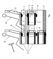
- an inventive battery case 1 is shown, are mounted on which seat rails 3 for several vehicle seats 2 directly. Shown are in Fig. Two front and one rear vehicle seat 2, in each case with its two seat rails 3 in which the vehicle seats 2 are guided and withforcegurtanitatien 4.
- Theforcegurtanitatien 4 are in particular buckles and / or end fittings.
- a recess 5 is provided in the battery case 1.
- the recess 5 is formed large enough, so that there is a relevant extension of the footwell of the rear occupant 6.
- the battery case 1 is provided on a side wall with a reinforcement 7, which is not shown in the side view (at the top in the figure), as it extends over the entire surface of the battery case 1.
- the invention thus enables optimal integration of a battery case in a vehicle.
Abstract
Description
- Die vorliegende Erfindung betrifft ein Batteriegehäuse zur Aufnahme der Innenteile einer Fahrzeugbatterie, wobei das Gehäuse zur Montage in einem Fahrzeug bestimmt ist. Weiters betrifft die Erfindung ein Batteriegehäuse mit einer Sitzschiene und eine Fahrzeugbatterie mit einem Fahrzeugsitz. Schließlich betrifft die Erfindung auch ein Verfahren zur Montage einer Fahrzeugbatterie mit einem Fahrzeugsitz in einem Fahrzeug.
- Derartige Batteriegehäuse werden insbesondere für Hochvolt-Batterien, die als Antriebsbatterien für Elektro- und Hybridfahrzeuge eingesetzt werden, genutzt. Hochvolt-Batterien sind zur Erreichung der geforderten Leistungsanforderungen üblicherweise relativ groß dimensioniert, so dass eine optimale Anordnung der Batterie mit ihrem Batteriegehäuse in einem Fahrzeug von Bedeutung ist.
- Aus der
DE 41 29 737 A1 ist ein elektrisch angetriebenes Fahrzeug bekannt, bei dem die Batterie vor der Hinterachse angeordnet ist. Die Batterie ist von einer umlaufenden Trägerstruktur umgeben. An der Trägerstruktur sind eine Bodenplatte und ein Deckel befestigt. Auf dem Deckel kann ein Rücksitz oder eine Rücksitzbank angeordnet sein. - Die
DE 10 2011 102 019 A1 offenbart eine Batteriemontagestruktur für ein Elektromotorfahrzeug. Dabei ist eine Batterieeinheit, umfassend mehrere Batteriemodule und Batteriemontageabschnitte, bedeckt von Abdeckgliedern und unterhalb eines Fahrzeugbodens angeordnet. Auf einem rückwärtigen Bodenabschnitt des Fahrzeugbodens ist ein Rücksitz angeordnet. - Die genannten Fahrzeugbatterien sind zwar relativ platzsparend teilweise unterhalb von Fahrzeugsitzen angeordnet, jedoch ist deren Integration in den Fahrzeugaufbau gering.
- Es ist eine Aufgabe der Erfindung, Batteriegehäuse der genannten Art in dieser Hinsicht zu verbessern und insbesondere ein Batteriegehäuse und eine Fahrzeugbatterie anzugeben, die optimal in ein Fahrzeug integrierbar sind. Weiters ist es eine Aufgabe der Erfindung ein geeignetes Verfahren zur Montage einer erfindungsgemäßen Fahrzeugbatterie in einem Fahrzeug anzugeben.
- Die Lösung der Aufgabe erfolgt durch ein Batteriegehäuse zur Aufnahme der Innenteile einer Fahrzeugbatterie, zur Montage in einem Fahrzeug, wobei an dem Batteriegehäuse Mittel zur Befestigung zumindest eines Fahrzeugsitzes ausgebildet sind.
- Erfindungsgemäß ist das Batteriegehäuse einer Fahrzeugbatterie also so ausgebildet, dass zumindest ein Fahrzeugsitz direkt auf dem Batteriegehäuse befestigt werden kann. Zusätzlich zur Funktion als Gehäuse für die Fahrzeugbatterie übernimmt daher das erfindungsgemäße Batteriegehäuse eine Funktion als tragendes Element des Fahrzeugaufbaus, in dem es zugleich die Befestigung zumindest eines Fahrzeugsitzes erlaubt.
- Das Batteriegehäuse beherbergt die üblichen Innenteile einer Fahrzeugbatterie, also insbesondere Batteriezellen, Kühl-/Heizelemente für die Batteriezellen, vorgefertigte Batteriemodule und/oder zumindest ein Batteriesteuergerät.
- Das Batteriegehäuse ist so ausgebildet, dass es zur sicheren Aufnahme der Innenteile der Batterie in ihrem Betriebszustand tauglich ist und sieht notwendigerweise vor, dass Anschlüsse der Batterie nach außen geführt werden.
- Weiterbildungen der Erfindung sind in den abhängigen Ansprüchen, der Beschreibung sowie der beigefügten Zeichnung angegeben.
- Bevorzugt bildet das Batteriegehäuse mitsamt seinen Innenteilen eine Antriebsbatterie eines Elektro- oder Hybridfahrzeuges.
- Bevorzugt sind an dem Batteriegehäuse Sitzschienen befestigbar. Das Batteriegehäuse ist daher dazu vorbereitet, dass Sitzschienen zur Lagerung zumindest eines Fahrzeugsitzes direkt auf das Gehäuse der Fahrzeugbatterie montiert werden. Bevorzugt können mehrere Fahrzeugsitze, insbesondere alle Sitze und gegebenenfalls Sitzbänke des Fahrzeuges auf dem Batteriegehäuse befestigt werden.
- Bevorzugt sind an dem Batteriegehäuse Anschraubpunkte zur Befestigung der Sitzschienen ausgebildet.
- Gemäß einer weiteren Ausführungsform sind an dem Batteriegehäuse Sicherheitsgurtanbindungen befestigbar. Zusätzlich zur Aufnahme zumindest eines Fahrzeugsitzes, kann am Batteriegehäuse auch zumindest eine Anbindung des Sicherheitsgurtes für diesen Sitz, insbesondere zumindest ein Gurtschloss und/oder ein Endbeschlag für einen Sicherheitsgurt, befestigt werden.
- Bevorzugt sind an dem Batteriegehäuse Anschraubpunkte zur Befestigung der Sicherheitsgurtanbindungen ausgebildet.
- Gemäß einer weiteren bevorzugten Ausführungsform ist an der Oberseite des Batteriegehäuses in Einbaulage zumindest eine Aussparung für zumindest einen Fußraum eines Insassen des Fahrzeuges ausgebildet. Die Oberseite weist also eine oder mehrere Einbuchtungen auf, die zur Erweiterung des Fußraumes der Passagiere des Fahrzeuges dienen.
- Gemäße einer weiteren Ausgestaltung der Erfindung weist zumindest eine Seitenwand des Batteriegehäuses eine Verstärkung auf. Die Verstärkung ist bevorzugt derart ausgeführt, dass die verstärkte Seitenwand des Gehäuses nicht nur die Batterie schützt, sondern zusätzlich den Innenraum des Fahrzeuges bei Unfällen schützt und daher als Maßnahme zur Verringerung des Risikos bei einem Seitencrash dient.
- Bevorzugt ist die Verstärkung des Batteriegehäuses als Wabenstruktur ausgeführt. Die Wandung des Batteriegehäuses kann beispielsweise selbst als Wabenstruktur ausgeführt sein, oder auch durch eine zusätzliche Verstärkerplatte mit Wabenstruktur verstärkt sein.
- Die Aufgabe der Erfindung wird auch gelöst durch ein erfindungsgemäßes Batteriegehäuse mit zumindest einer Sitzschiene, wobei die zumindest eine Sitzschiene an dem Batteriegehäuse befestigt ist.
- Weiters wird die Aufgabe der Erfindung gelöst durch eine Fahrzeugbatterie umfassend ein erfindungsgemäßes Batteriegehäuse mit zumindest einem
- Fahrzeugsitz, wobei der zumindest eine Fahrzeugsitz an dem Batteriegehäuse befestigt ist. Der Fahrzeugsitz ist dabei üblicherweise mittelbar, insbesondere über Sitzschienen, am Batteriegehäuse befestigt.
- In einem erfindungsgemäßen Verfahren zur Montage einer Fahrzeugbatterie mit zumindest einem Fahrzeugsitz in einem Fahrzeug, wird eine Fahrzeugbatterie mitsamt einem oder mehreren zuvor darauf befestigten Fahrzeugsitzen in die Karosserie des Fahrzeuges geschoben und anschließend das Batteriegehäuse im Fahrzeug befestigt. Bevorzugt wird die Einheit aus Fahrzeugbatterie und Fahrzeugsitz bzw. Fahrzeugsitzen von unten in das Fahrzeug geschoben.
- Die Erfindung wird im Folgenden beispielhaft unter Bezugnahme auf die Zeichnung beschrieben.
- Fig.
- ist eine schematische Darstellung eines erfindungsgemäßen Batteriegehäuses von der Seite (obere Darstellung) und von oben (untere Darstellung).
- In der Fig. ist ein erfindungsgemäßes Batteriegehäuse 1 dargestellt, an welchem Sitzschienen 3 für mehrere Fahrzeugsitze 2 direkt montiert sind. Dargestellt sind in der Fig. zwei vordere und ein hinterer Fahrzeugsitz 2, jeweils mit deren beiden Sitzschienen 3 in welchen die Fahrzeugsitze 2 geführt sind und mit Sicherheitsgurtanbindungen 4. Die Sicherheitsgurtanbindungen 4 sind insbesondere Gurtschlösser und/oder Endbeschläge. Zur Erweiterung des Fußraumes eines Fontpassagieres, dargestellt durch den hinteren Insassen 6, ist eine Aussparung 5 im Batteriegehäuse 1 vorgesehen. Die Aussparung 5 ist groß genug ausgebildet, so dass sich eine relevante Erweiterung des Fußraumes des hinteren Insassen 6 ergibt. Das Batteriegehäuse 1 ist an einer Seitenwand mit einer Verstärkung 7 versehen, die in der seitlichen Darstellung (oben in der Fig.) nicht dargestellt ist, da sie sich über die gesamte Fläche des Batteriegehäuses 1 erstreckt.
- Die Erfindung ermöglicht somit eine optimale Integration eines Batteriegehäuses in ein Fahrzeug.
-
- 1
- Batteriegehäuse
- 2
- Fahrzeugsitz
- 3
- Sitzschiene
- 4
- Sicherheitsgurtanbindung
- 5
- Aussparung
- 6
- Insasse
- 7
- Verstärkung
Claims (11)
- Batteriegehäuse zur Aufnahme der Innenteile einer Fahrzeugbatterie, zur Montage in einem Fahrzeug,
dadurch gekennzeichnet, dass an dem Batteriegehäuse (1) Mittel zur Befestigung zumindest eines Fahrzeugsitzes (2) ausgebildet sind. - Batteriegehäuse nach Anspruch 1,
dadurch gekennzeichnet, dass an dem Batteriegehäuse (1) Sitzschienen (3) befestigbar sind. - Batteriegehäuse nach zumindest einem der vorhergehenden Ansprüche,
dadurch gekennzeichnet, dass an dem Batteriegehäuse (1) Anschraubpunkte zur Befestigung der Sitzschienen (3) ausgebildet sind. - Batteriegehäuse nach zumindest einem der vorhergehenden Ansprüche,
dadurch gekennzeichnet, dass an dem Batteriegehäuse (1) Sicherheitsgurtanbindungen (4) befestigbar sind. - Batteriegehäuse nach Anspruch 4,
dadurch gekennzeichnet, dass an dem Batteriegehäuse (1) Anschraubpunkte zur Befestigung der Sicherheitsgurtanbindungen (4) ausgebildet sind. - Batteriegehäuse nach zumindest einem der vorhergehenden Ansprüche,
dadurch gekennzeichnet, dass an der Oberseite des Batteriegehäuses (1) in Einbaulage zumindest eine Aussparung (5) für zumindest einen Fußraum eines Insassen (6) des Fahrzeuges ausgebildet ist. - Batteriegehäuse nach zumindest einem der vorhergehenden Ansprüche,
dadurch gekennzeichnet, dass zumindest eine Seitenwand des Batteriegehäuses (1) eine Verstärkung (7) aufweist. - Batteriegehäuse nach Anspruch 7,
dadurch gekennzeichnet, dass die Verstärkung (7) als Wabenstruktur ausgeführt ist. - Batteriegehäuse nach zumindest einem der vorhergehenden Ansprüche mit zumindest einer Sitzschiene,
dadurch gekennzeichnet, dass die zumindest eine Sitzschiene (3) an dem Batteriegehäuse (1) befestigt ist. - Fahrzeugbatterie umfassend ein Batteriegehäuse nach zumindest einem der vorhergehenden Ansprüche mit zumindest einem Fahrzeugsitz,
dadurch gekennzeichnet, dass der zumindest eine Fahrzeugsitz (2) an dem Batteriegehäuse (1) befestigt ist. - Verfahren zur Montage einer Fahrzeugbatterie mit zumindest einem Fahrzeugsitz nach Anspruch 10 in einem Fahrzeug, gekennzeichnet dadurch, dass die Fahrzeugbatterie mitsamt dem darauf befestigten Fahrzeugsitz (2) in die Karosserie des Fahrzeuges geschoben wird und anschließend im Fahrzeug befestigt wird.
Priority Applications (4)
| Application Number | Priority Date | Filing Date | Title |
|---|---|---|---|
| EP12167123.4A EP2662230B1 (de) | 2012-05-08 | 2012-05-08 | Batteriegehäuse |
| KR1020130051060A KR20130125322A (ko) | 2012-05-08 | 2013-05-07 | 배터리 하우징 |
| CN2013101657957A CN103390733A (zh) | 2012-05-08 | 2013-05-08 | 电池外壳 |
| US13/889,624 US20130299257A1 (en) | 2012-05-08 | 2013-05-08 | Battery housing |
Applications Claiming Priority (1)
| Application Number | Priority Date | Filing Date | Title |
|---|---|---|---|
| EP12167123.4A EP2662230B1 (de) | 2012-05-08 | 2012-05-08 | Batteriegehäuse |
Publications (2)
| Publication Number | Publication Date |
|---|---|
| EP2662230A1 true EP2662230A1 (de) | 2013-11-13 |
| EP2662230B1 EP2662230B1 (de) | 2018-01-24 |
Family
ID=46177279
Family Applications (1)
| Application Number | Title | Priority Date | Filing Date |
|---|---|---|---|
| EP12167123.4A Active EP2662230B1 (de) | 2012-05-08 | 2012-05-08 | Batteriegehäuse |
Country Status (4)
| Country | Link |
|---|---|
| US (1) | US20130299257A1 (de) |
| EP (1) | EP2662230B1 (de) |
| KR (1) | KR20130125322A (de) |
| CN (1) | CN103390733A (de) |
Cited By (2)
| Publication number | Priority date | Publication date | Assignee | Title |
|---|---|---|---|---|
| DE102016202909A1 (de) * | 2016-02-25 | 2017-08-31 | Bayerische Motoren Werke Aktiengesellschaft | Energiespeichergehäuse, Fahrzeug mit einem Energiespeichergehäuse und Set aus Energiespeichergehäusen |
| DE102021202476A1 (de) | 2021-03-15 | 2022-09-15 | Psa Automobiles Sa | Gehäuse für eine Kraftfahrzeugbatterie |
Families Citing this family (4)
| Publication number | Priority date | Publication date | Assignee | Title |
|---|---|---|---|---|
| DE102013114317B4 (de) * | 2013-12-18 | 2023-08-17 | Dr. Ing. H.C. F. Porsche Aktiengesellschaft | Batterievorrichtung mit einem Batteriegehäuse für ein Kraftfahrzeug |
| JP7248371B2 (ja) * | 2018-11-29 | 2023-03-29 | ダイハツ工業株式会社 | シート構造 |
| DE102019203042A1 (de) | 2019-03-06 | 2020-09-10 | Ford Global Technologies, Llc | Baugruppe mit Fahrzeugbatterie und Fahrzeugsitz für ein Hybridkraftfahrzeug |
| KR102633309B1 (ko) | 2019-06-26 | 2024-02-06 | 현대자동차주식회사 | 차체구조물 및 이를 포함하는 차량 |
Citations (6)
| Publication number | Priority date | Publication date | Assignee | Title |
|---|---|---|---|---|
| FR2006674A1 (de) * | 1968-04-22 | 1970-01-02 | Allis Chalmers Mfg Co | |
| DE2311894A1 (de) * | 1970-05-05 | 1974-09-12 | Clark Equipment Co | Einstellbarer sitz fuer industriefahrzeuge |
| DE4129737A1 (de) | 1991-09-06 | 1993-03-11 | Bayerische Motoren Werke Ag | Elektrisch angetriebenes fahrzeug, insbesondere ein personenkraftwagen |
| JPH06127456A (ja) * | 1992-10-19 | 1994-05-10 | Kubota Corp | 小型電動車のバッテリー保持構造 |
| JP2004345451A (ja) * | 2003-05-21 | 2004-12-09 | Honda Motor Co Ltd | 高圧電装部品の冷却構造 |
| DE102011102019A1 (de) | 2010-06-02 | 2011-12-08 | Mazda Motor Corporation | Batteriemontagestruktur for ein Elektromotorfahrzeug |
Family Cites Families (10)
| Publication number | Priority date | Publication date | Assignee | Title |
|---|---|---|---|---|
| JP4294372B2 (ja) * | 2003-05-21 | 2009-07-08 | 本田技研工業株式会社 | 高圧電装部品の車載構造 |
| WO2005051697A1 (ja) * | 2003-11-28 | 2005-06-09 | Toyota Jidosha Kabushiki Kaisha | 車両用バッテリパックの搭載構造 |
| JP5141026B2 (ja) * | 2006-02-27 | 2013-02-13 | トヨタ自動車株式会社 | 蓄電パックの車載構造 |
| JP4225363B2 (ja) * | 2007-07-24 | 2009-02-18 | トヨタ自動車株式会社 | 内燃機関および回転電機を動力源として備える車両 |
| EP2402191B1 (de) * | 2009-02-24 | 2016-09-28 | Nissan Motor Co., Ltd. | Batterieinstallationsstruktur |
| WO2011013634A1 (ja) * | 2009-07-27 | 2011-02-03 | 本田技研工業株式会社 | 車両の電装部品搭載構造 |
| JP5560922B2 (ja) * | 2010-06-08 | 2014-07-30 | 日産自動車株式会社 | 電動車両のバッテリパック収納構造 |
| US8336658B2 (en) * | 2010-12-22 | 2012-12-25 | Tesla Motors, Inc. | Augmented vehicle seat mount |
| US20130180788A1 (en) * | 2012-01-18 | 2013-07-18 | Bruce Jin | Electric Car |
| JP5870457B2 (ja) * | 2012-11-08 | 2016-03-01 | 本田技研工業株式会社 | 電動車両 |
-
2012
- 2012-05-08 EP EP12167123.4A patent/EP2662230B1/de active Active
-
2013
- 2013-05-07 KR KR1020130051060A patent/KR20130125322A/ko active Search and Examination
- 2013-05-08 CN CN2013101657957A patent/CN103390733A/zh active Pending
- 2013-05-08 US US13/889,624 patent/US20130299257A1/en not_active Abandoned
Patent Citations (6)
| Publication number | Priority date | Publication date | Assignee | Title |
|---|---|---|---|---|
| FR2006674A1 (de) * | 1968-04-22 | 1970-01-02 | Allis Chalmers Mfg Co | |
| DE2311894A1 (de) * | 1970-05-05 | 1974-09-12 | Clark Equipment Co | Einstellbarer sitz fuer industriefahrzeuge |
| DE4129737A1 (de) | 1991-09-06 | 1993-03-11 | Bayerische Motoren Werke Ag | Elektrisch angetriebenes fahrzeug, insbesondere ein personenkraftwagen |
| JPH06127456A (ja) * | 1992-10-19 | 1994-05-10 | Kubota Corp | 小型電動車のバッテリー保持構造 |
| JP2004345451A (ja) * | 2003-05-21 | 2004-12-09 | Honda Motor Co Ltd | 高圧電装部品の冷却構造 |
| DE102011102019A1 (de) | 2010-06-02 | 2011-12-08 | Mazda Motor Corporation | Batteriemontagestruktur for ein Elektromotorfahrzeug |
Cited By (3)
| Publication number | Priority date | Publication date | Assignee | Title |
|---|---|---|---|---|
| DE102016202909A1 (de) * | 2016-02-25 | 2017-08-31 | Bayerische Motoren Werke Aktiengesellschaft | Energiespeichergehäuse, Fahrzeug mit einem Energiespeichergehäuse und Set aus Energiespeichergehäusen |
| US10583727B2 (en) | 2016-02-25 | 2020-03-10 | Bayerische Motoren Werke Aktiengesellschaft | Energy storage housing, vehicle with an energy storage housing, and set of energy storage housings |
| DE102021202476A1 (de) | 2021-03-15 | 2022-09-15 | Psa Automobiles Sa | Gehäuse für eine Kraftfahrzeugbatterie |
Also Published As
| Publication number | Publication date |
|---|---|
| US20130299257A1 (en) | 2013-11-14 |
| KR20130125322A (ko) | 2013-11-18 |
| EP2662230B1 (de) | 2018-01-24 |
| CN103390733A (zh) | 2013-11-13 |
Similar Documents
| Publication | Publication Date | Title |
|---|---|---|
| EP2662230B1 (de) | Batteriegehäuse | |
| EP2766247B1 (de) | Aufbaustruktur für ein elektrisch angetriebenes personen-kraftfahrzeug | |
| DE10018407B4 (de) | Karosserie eines Kraftfahrzeuges mit einem Sitzmodul | |
| DE102019130548A1 (de) | Verfahren zum montieren eines fahrzeugs, einschliesslich eines integrierten innenmoduls und eines top-hat | |
| DE102016203209A1 (de) | Zumindest teilweise elektrisch betreibbares Kraftfahrzeug | |
| EP2509830B1 (de) | Fahrzeuglenkrad | |
| DE19905025C2 (de) | Airbagmodul | |
| EP2722225B2 (de) | Fahrgestell eines Reisewohnmobils oder ähnlicher Fahrzeuge sowie Chassis für ein solches Fahrgestell | |
| EP3617040B1 (de) | Fahrerhausfrontmodul und verfahren zur herstellung eines fahrerhauses | |
| WO2021043984A1 (de) | Energiespeicher-bodengruppe für einen kraftwagen | |
| WO2009021576A1 (de) | Fahrzeug mit einer karosserie und einem antriebssystem | |
| DE102010046126A1 (de) | Kraftfahrzeugsitzmodul | |
| DE102017002249B4 (de) | Kraftfahrzeug und Fahrzeugkarosserie für ein Kraftfahrzeug | |
| EP1324900A1 (de) | Gehäuse für einen aufblasbaren gassack eines kraftfahrzeuges | |
| WO2016015960A1 (de) | Hochvoltenergiespeicher mit lokal verstärktem gehäuse sowie entsprechendes herstellungsverfahren | |
| DE102017211372A1 (de) | Batterie sowie Fahrzeug mit einer solchen Batterie | |
| DE102018210124A1 (de) | Batteriegehäuse und Kraftfahrzeug mit einem solchen Batteriegehäuse | |
| DE102017211366A1 (de) | Batterie für einen elektrischen Antrieb eines Kraftwagens | |
| DE102013004833A1 (de) | Rohbaustruktur eines Straßenfahrzeugs | |
| DE10248654B4 (de) | Verfahren zum Herstellen einer Kraftfahrzeugkarosserie und Kraftfahrzeugkarosserie | |
| DE102014013117A1 (de) | Kraftfahrzeug | |
| DE10027122B4 (de) | Airbagmodul-Anordnung in einem Kraftfahrzeug | |
| DE102010016748A1 (de) | Kraftfahrzeug | |
| DE102017211362A1 (de) | Trageinrichtung einer Batterie eines elektrischen Antriebsstrangs für jeweilige Kraftwägen einer Fahrzeugbaureihe | |
| DE102010045144B4 (de) | Karosserie für einen Kraftwagen |
Legal Events
| Date | Code | Title | Description |
|---|---|---|---|
| PUAI | Public reference made under article 153(3) epc to a published international application that has entered the european phase |
Free format text: ORIGINAL CODE: 0009012 |
|
| 17P | Request for examination filed |
Effective date: 20121220 |
|
| AK | Designated contracting states |
Kind code of ref document: A1 Designated state(s): AL AT BE BG CH CY CZ DE DK EE ES FI FR GB GR HR HU IE IS IT LI LT LU LV MC MK MT NL NO PL PT RO RS SE SI SK SM TR |
|
| AX | Request for extension of the european patent |
Extension state: BA ME |
|
| RBV | Designated contracting states (corrected) |
Designated state(s): AL AT BE BG CH CY CZ DE DK EE ES FI FR GB GR HR HU IE IS IT LI LT LU LV MC MK MT NL NO PL PT RO RS SE SI SK SM TR |
|
| 17Q | First examination report despatched |
Effective date: 20170403 |
|
| GRAP | Despatch of communication of intention to grant a patent |
Free format text: ORIGINAL CODE: EPIDOSNIGR1 |
|
| INTG | Intention to grant announced |
Effective date: 20170928 |
|
| GRAS | Grant fee paid |
Free format text: ORIGINAL CODE: EPIDOSNIGR3 |
|
| GRAA | (expected) grant |
Free format text: ORIGINAL CODE: 0009210 |
|
| AK | Designated contracting states |
Kind code of ref document: B1 Designated state(s): AL AT BE BG CH CY CZ DE DK EE ES FI FR GB GR HR HU IE IS IT LI LT LU LV MC MK MT NL NO PL PT RO RS SE SI SK SM TR |
|
| REG | Reference to a national code |
Ref country code: GB Ref legal event code: FG4D Free format text: NOT ENGLISH |
|
| REG | Reference to a national code |
Ref country code: CH Ref legal event code: EP |
|
| REG | Reference to a national code |
Ref country code: AT Ref legal event code: REF Ref document number: 965580 Country of ref document: AT Kind code of ref document: T Effective date: 20180215 |
|
| REG | Reference to a national code |
Ref country code: IE Ref legal event code: FG4D Free format text: LANGUAGE OF EP DOCUMENT: GERMAN |
|
| REG | Reference to a national code |
Ref country code: DE Ref legal event code: R096 Ref document number: 502012012054 Country of ref document: DE |
|
| REG | Reference to a national code |
Ref country code: FR Ref legal event code: PLFP Year of fee payment: 7 |
|
| REG | Reference to a national code |
Ref country code: NL Ref legal event code: MP Effective date: 20180124 |
|
| REG | Reference to a national code |
Ref country code: LT Ref legal event code: MG4D |
|
| PG25 | Lapsed in a contracting state [announced via postgrant information from national office to epo] |
Ref country code: NL Free format text: LAPSE BECAUSE OF FAILURE TO SUBMIT A TRANSLATION OF THE DESCRIPTION OR TO PAY THE FEE WITHIN THE PRESCRIBED TIME-LIMIT Effective date: 20180124 |
|
| PG25 | Lapsed in a contracting state [announced via postgrant information from national office to epo] |
Ref country code: CY Free format text: LAPSE BECAUSE OF FAILURE TO SUBMIT A TRANSLATION OF THE DESCRIPTION OR TO PAY THE FEE WITHIN THE PRESCRIBED TIME-LIMIT Effective date: 20180124 Ref country code: NO Free format text: LAPSE BECAUSE OF FAILURE TO SUBMIT A TRANSLATION OF THE DESCRIPTION OR TO PAY THE FEE WITHIN THE PRESCRIBED TIME-LIMIT Effective date: 20180424 Ref country code: HR Free format text: LAPSE BECAUSE OF FAILURE TO SUBMIT A TRANSLATION OF THE DESCRIPTION OR TO PAY THE FEE WITHIN THE PRESCRIBED TIME-LIMIT Effective date: 20180124 Ref country code: FI Free format text: LAPSE BECAUSE OF FAILURE TO SUBMIT A TRANSLATION OF THE DESCRIPTION OR TO PAY THE FEE WITHIN THE PRESCRIBED TIME-LIMIT Effective date: 20180124 Ref country code: ES Free format text: LAPSE BECAUSE OF FAILURE TO SUBMIT A TRANSLATION OF THE DESCRIPTION OR TO PAY THE FEE WITHIN THE PRESCRIBED TIME-LIMIT Effective date: 20180124 Ref country code: LT Free format text: LAPSE BECAUSE OF FAILURE TO SUBMIT A TRANSLATION OF THE DESCRIPTION OR TO PAY THE FEE WITHIN THE PRESCRIBED TIME-LIMIT Effective date: 20180124 |
|
| PG25 | Lapsed in a contracting state [announced via postgrant information from national office to epo] |
Ref country code: RS Free format text: LAPSE BECAUSE OF FAILURE TO SUBMIT A TRANSLATION OF THE DESCRIPTION OR TO PAY THE FEE WITHIN THE PRESCRIBED TIME-LIMIT Effective date: 20180124 Ref country code: PL Free format text: LAPSE BECAUSE OF FAILURE TO SUBMIT A TRANSLATION OF THE DESCRIPTION OR TO PAY THE FEE WITHIN THE PRESCRIBED TIME-LIMIT Effective date: 20180124 Ref country code: SE Free format text: LAPSE BECAUSE OF FAILURE TO SUBMIT A TRANSLATION OF THE DESCRIPTION OR TO PAY THE FEE WITHIN THE PRESCRIBED TIME-LIMIT Effective date: 20180124 Ref country code: LV Free format text: LAPSE BECAUSE OF FAILURE TO SUBMIT A TRANSLATION OF THE DESCRIPTION OR TO PAY THE FEE WITHIN THE PRESCRIBED TIME-LIMIT Effective date: 20180124 Ref country code: BG Free format text: LAPSE BECAUSE OF FAILURE TO SUBMIT A TRANSLATION OF THE DESCRIPTION OR TO PAY THE FEE WITHIN THE PRESCRIBED TIME-LIMIT Effective date: 20180424 Ref country code: IS Free format text: LAPSE BECAUSE OF FAILURE TO SUBMIT A TRANSLATION OF THE DESCRIPTION OR TO PAY THE FEE WITHIN THE PRESCRIBED TIME-LIMIT Effective date: 20180524 Ref country code: GR Free format text: LAPSE BECAUSE OF FAILURE TO SUBMIT A TRANSLATION OF THE DESCRIPTION OR TO PAY THE FEE WITHIN THE PRESCRIBED TIME-LIMIT Effective date: 20180425 |
|
| PG25 | Lapsed in a contracting state [announced via postgrant information from national office to epo] |
Ref country code: MT Free format text: LAPSE BECAUSE OF FAILURE TO SUBMIT A TRANSLATION OF THE DESCRIPTION OR TO PAY THE FEE WITHIN THE PRESCRIBED TIME-LIMIT Effective date: 20180124 |
|
| REG | Reference to a national code |
Ref country code: DE Ref legal event code: R097 Ref document number: 502012012054 Country of ref document: DE |
|
| PG25 | Lapsed in a contracting state [announced via postgrant information from national office to epo] |
Ref country code: AL Free format text: LAPSE BECAUSE OF FAILURE TO SUBMIT A TRANSLATION OF THE DESCRIPTION OR TO PAY THE FEE WITHIN THE PRESCRIBED TIME-LIMIT Effective date: 20180124 Ref country code: RO Free format text: LAPSE BECAUSE OF FAILURE TO SUBMIT A TRANSLATION OF THE DESCRIPTION OR TO PAY THE FEE WITHIN THE PRESCRIBED TIME-LIMIT Effective date: 20180124 Ref country code: IT Free format text: LAPSE BECAUSE OF FAILURE TO SUBMIT A TRANSLATION OF THE DESCRIPTION OR TO PAY THE FEE WITHIN THE PRESCRIBED TIME-LIMIT Effective date: 20180124 Ref country code: EE Free format text: LAPSE BECAUSE OF FAILURE TO SUBMIT A TRANSLATION OF THE DESCRIPTION OR TO PAY THE FEE WITHIN THE PRESCRIBED TIME-LIMIT Effective date: 20180124 |
|
| PG25 | Lapsed in a contracting state [announced via postgrant information from national office to epo] |
Ref country code: SK Free format text: LAPSE BECAUSE OF FAILURE TO SUBMIT A TRANSLATION OF THE DESCRIPTION OR TO PAY THE FEE WITHIN THE PRESCRIBED TIME-LIMIT Effective date: 20180124 Ref country code: DK Free format text: LAPSE BECAUSE OF FAILURE TO SUBMIT A TRANSLATION OF THE DESCRIPTION OR TO PAY THE FEE WITHIN THE PRESCRIBED TIME-LIMIT Effective date: 20180124 Ref country code: CZ Free format text: LAPSE BECAUSE OF FAILURE TO SUBMIT A TRANSLATION OF THE DESCRIPTION OR TO PAY THE FEE WITHIN THE PRESCRIBED TIME-LIMIT Effective date: 20180124 Ref country code: SM Free format text: LAPSE BECAUSE OF FAILURE TO SUBMIT A TRANSLATION OF THE DESCRIPTION OR TO PAY THE FEE WITHIN THE PRESCRIBED TIME-LIMIT Effective date: 20180124 |
|
| PLBE | No opposition filed within time limit |
Free format text: ORIGINAL CODE: 0009261 |
|
| STAA | Information on the status of an ep patent application or granted ep patent |
Free format text: STATUS: NO OPPOSITION FILED WITHIN TIME LIMIT |
|
| REG | Reference to a national code |
Ref country code: CH Ref legal event code: PL |
|
| 26N | No opposition filed |
Effective date: 20181025 |
|
| REG | Reference to a national code |
Ref country code: BE Ref legal event code: MM Effective date: 20180531 |
|
| PG25 | Lapsed in a contracting state [announced via postgrant information from national office to epo] |
Ref country code: MC Free format text: LAPSE BECAUSE OF FAILURE TO SUBMIT A TRANSLATION OF THE DESCRIPTION OR TO PAY THE FEE WITHIN THE PRESCRIBED TIME-LIMIT Effective date: 20180124 |
|
| REG | Reference to a national code |
Ref country code: IE Ref legal event code: MM4A |
|
| PG25 | Lapsed in a contracting state [announced via postgrant information from national office to epo] |
Ref country code: SI Free format text: LAPSE BECAUSE OF FAILURE TO SUBMIT A TRANSLATION OF THE DESCRIPTION OR TO PAY THE FEE WITHIN THE PRESCRIBED TIME-LIMIT Effective date: 20180124 Ref country code: CH Free format text: LAPSE BECAUSE OF NON-PAYMENT OF DUE FEES Effective date: 20180531 Ref country code: LI Free format text: LAPSE BECAUSE OF NON-PAYMENT OF DUE FEES Effective date: 20180531 |
|
| PG25 | Lapsed in a contracting state [announced via postgrant information from national office to epo] |
Ref country code: LU Free format text: LAPSE BECAUSE OF NON-PAYMENT OF DUE FEES Effective date: 20180508 |
|
| PG25 | Lapsed in a contracting state [announced via postgrant information from national office to epo] |
Ref country code: IE Free format text: LAPSE BECAUSE OF NON-PAYMENT OF DUE FEES Effective date: 20180508 |
|
| PG25 | Lapsed in a contracting state [announced via postgrant information from national office to epo] |
Ref country code: BE Free format text: LAPSE BECAUSE OF NON-PAYMENT OF DUE FEES Effective date: 20180531 |
|
| REG | Reference to a national code |
Ref country code: AT Ref legal event code: MM01 Ref document number: 965580 Country of ref document: AT Kind code of ref document: T Effective date: 20180508 |
|
| PGFP | Annual fee paid to national office [announced via postgrant information from national office to epo] |
Ref country code: FR Payment date: 20190523 Year of fee payment: 8 |
|
| PG25 | Lapsed in a contracting state [announced via postgrant information from national office to epo] |
Ref country code: AT Free format text: LAPSE BECAUSE OF NON-PAYMENT OF DUE FEES Effective date: 20180508 |
|
| PGFP | Annual fee paid to national office [announced via postgrant information from national office to epo] |
Ref country code: GB Payment date: 20190521 Year of fee payment: 8 |
|
| PG25 | Lapsed in a contracting state [announced via postgrant information from national office to epo] |
Ref country code: TR Free format text: LAPSE BECAUSE OF FAILURE TO SUBMIT A TRANSLATION OF THE DESCRIPTION OR TO PAY THE FEE WITHIN THE PRESCRIBED TIME-LIMIT Effective date: 20180124 |
|
| PG25 | Lapsed in a contracting state [announced via postgrant information from national office to epo] |
Ref country code: HU Free format text: LAPSE BECAUSE OF FAILURE TO SUBMIT A TRANSLATION OF THE DESCRIPTION OR TO PAY THE FEE WITHIN THE PRESCRIBED TIME-LIMIT; INVALID AB INITIO Effective date: 20120508 Ref country code: PT Free format text: LAPSE BECAUSE OF FAILURE TO SUBMIT A TRANSLATION OF THE DESCRIPTION OR TO PAY THE FEE WITHIN THE PRESCRIBED TIME-LIMIT Effective date: 20180124 |
|
| PG25 | Lapsed in a contracting state [announced via postgrant information from national office to epo] |
Ref country code: MK Free format text: LAPSE BECAUSE OF NON-PAYMENT OF DUE FEES Effective date: 20180124 |
|
| GBPC | Gb: european patent ceased through non-payment of renewal fee |
Effective date: 20200508 |
|
| PG25 | Lapsed in a contracting state [announced via postgrant information from national office to epo] |
Ref country code: FR Free format text: LAPSE BECAUSE OF NON-PAYMENT OF DUE FEES Effective date: 20200531 Ref country code: GB Free format text: LAPSE BECAUSE OF NON-PAYMENT OF DUE FEES Effective date: 20200508 |
|
| REG | Reference to a national code |
Ref country code: DE Ref legal event code: R081 Ref document number: 502012012054 Country of ref document: DE Owner name: MAGNA STEYR FAHRZEUGTECHNIK GMBH & CO KG, AT Free format text: FORMER OWNER: MAGNA STEYR FAHRZEUGTECHNIK AG & CO. KG, GRAZ, AT |
|
| PGFP | Annual fee paid to national office [announced via postgrant information from national office to epo] |
Ref country code: DE Payment date: 20230519 Year of fee payment: 12 |