EP2655768B1 - Device for applying laterally retracting doors, particularly for pieces of furniture - Google Patents
Device for applying laterally retracting doors, particularly for pieces of furniture Download PDFInfo
- Publication number
- EP2655768B1 EP2655768B1 EP11790969.7A EP11790969A EP2655768B1 EP 2655768 B1 EP2655768 B1 EP 2655768B1 EP 11790969 A EP11790969 A EP 11790969A EP 2655768 B1 EP2655768 B1 EP 2655768B1
- Authority
- EP
- European Patent Office
- Prior art keywords
- upright
- door
- compartment
- pair
- furniture
- Prior art date
- Legal status (The legal status is an assumption and is not a legal conclusion. Google has not performed a legal analysis and makes no representation as to the accuracy of the status listed.)
- Active
Links
- 238000013016 damping Methods 0.000 claims description 13
- 230000010355 oscillation Effects 0.000 claims description 9
- 238000000605 extraction Methods 0.000 claims description 7
- 238000009826 distribution Methods 0.000 claims description 6
- 230000001360 synchronised effect Effects 0.000 claims description 5
- 238000013519 translation Methods 0.000 claims description 5
- 238000003780 insertion Methods 0.000 claims description 4
- 230000037431 insertion Effects 0.000 claims description 4
- 230000000717 retained effect Effects 0.000 claims description 3
- 239000000523 sample Substances 0.000 claims description 3
- LRUUNMYPIBZBQH-UHFFFAOYSA-N Methazole Chemical compound O=C1N(C)C(=O)ON1C1=CC=C(Cl)C(Cl)=C1 LRUUNMYPIBZBQH-UHFFFAOYSA-N 0.000 description 5
- 230000000670 limiting effect Effects 0.000 description 5
- 230000004308 accommodation Effects 0.000 description 4
- 238000000034 method Methods 0.000 description 4
- 239000007787 solid Substances 0.000 description 2
- 230000000007 visual effect Effects 0.000 description 2
- 230000004913 activation Effects 0.000 description 1
- 230000006978 adaptation Effects 0.000 description 1
- 238000012512 characterization method Methods 0.000 description 1
- 238000005352 clarification Methods 0.000 description 1
- 230000006866 deterioration Effects 0.000 description 1
- 239000000428 dust Substances 0.000 description 1
- 230000000694 effects Effects 0.000 description 1
- 230000001788 irregular Effects 0.000 description 1
- 238000005304 joining Methods 0.000 description 1
- 238000012423 maintenance Methods 0.000 description 1
- 230000014759 maintenance of location Effects 0.000 description 1
- 238000004519 manufacturing process Methods 0.000 description 1
- 238000012986 modification Methods 0.000 description 1
- 230000004048 modification Effects 0.000 description 1
- 230000000630 rising effect Effects 0.000 description 1
- 238000011144 upstream manufacturing Methods 0.000 description 1
Images


Classifications
-
- E—FIXED CONSTRUCTIONS
- E05—LOCKS; KEYS; WINDOW OR DOOR FITTINGS; SAFES
- E05F—DEVICES FOR MOVING WINGS INTO OPEN OR CLOSED POSITION; CHECKS FOR WINGS; WING FITTINGS NOT OTHERWISE PROVIDED FOR, CONCERNED WITH THE FUNCTIONING OF THE WING
- E05F5/00—Braking devices, e.g. checks; Stops; Buffers
-
- E—FIXED CONSTRUCTIONS
- E05—LOCKS; KEYS; WINDOW OR DOOR FITTINGS; SAFES
- E05D—HINGES OR SUSPENSION DEVICES FOR DOORS, WINDOWS OR WINGS
- E05D15/00—Suspension arrangements for wings
- E05D15/48—Suspension arrangements for wings allowing alternative movements
- E05D15/52—Suspension arrangements for wings allowing alternative movements for opening about a vertical as well as a horizontal axis
-
- E—FIXED CONSTRUCTIONS
- E05—LOCKS; KEYS; WINDOW OR DOOR FITTINGS; SAFES
- E05D—HINGES OR SUSPENSION DEVICES FOR DOORS, WINDOWS OR WINGS
- E05D15/00—Suspension arrangements for wings
- E05D15/56—Suspension arrangements for wings with successive different movements
- E05D15/58—Suspension arrangements for wings with successive different movements with both swinging and sliding movements
-
- E—FIXED CONSTRUCTIONS
- E05—LOCKS; KEYS; WINDOW OR DOOR FITTINGS; SAFES
- E05F—DEVICES FOR MOVING WINGS INTO OPEN OR CLOSED POSITION; CHECKS FOR WINGS; WING FITTINGS NOT OTHERWISE PROVIDED FOR, CONCERNED WITH THE FUNCTIONING OF THE WING
- E05F5/00—Braking devices, e.g. checks; Stops; Buffers
- E05F5/003—Braking devices, e.g. checks; Stops; Buffers for sliding wings
-
- E—FIXED CONSTRUCTIONS
- E05—LOCKS; KEYS; WINDOW OR DOOR FITTINGS; SAFES
- E05Y—INDEXING SCHEME RELATING TO HINGES OR OTHER SUSPENSION DEVICES FOR DOORS, WINDOWS OR WINGS AND DEVICES FOR MOVING WINGS INTO OPEN OR CLOSED POSITION, CHECKS FOR WINGS AND WING FITTINGS NOT OTHERWISE PROVIDED FOR, CONCERNED WITH THE FUNCTIONING OF THE WING
- E05Y2201/00—Constructional elements; Accessories therefore
- E05Y2201/60—Suspension or transmission members; Accessories therefore
- E05Y2201/606—Accessories therefore
- E05Y2201/62—Synchronisation of transmission members
-
- E—FIXED CONSTRUCTIONS
- E05—LOCKS; KEYS; WINDOW OR DOOR FITTINGS; SAFES
- E05Y—INDEXING SCHEME RELATING TO HINGES OR OTHER SUSPENSION DEVICES FOR DOORS, WINDOWS OR WINGS AND DEVICES FOR MOVING WINGS INTO OPEN OR CLOSED POSITION, CHECKS FOR WINGS AND WING FITTINGS NOT OTHERWISE PROVIDED FOR, CONCERNED WITH THE FUNCTIONING OF THE WING
- E05Y2201/00—Constructional elements; Accessories therefore
- E05Y2201/60—Suspension or transmission members; Accessories therefore
- E05Y2201/622—Suspension or transmission members elements
- E05Y2201/624—Arms
- E05Y2201/626—Levers
-
- E—FIXED CONSTRUCTIONS
- E05—LOCKS; KEYS; WINDOW OR DOOR FITTINGS; SAFES
- E05Y—INDEXING SCHEME RELATING TO HINGES OR OTHER SUSPENSION DEVICES FOR DOORS, WINDOWS OR WINGS AND DEVICES FOR MOVING WINGS INTO OPEN OR CLOSED POSITION, CHECKS FOR WINGS AND WING FITTINGS NOT OTHERWISE PROVIDED FOR, CONCERNED WITH THE FUNCTIONING OF THE WING
- E05Y2900/00—Application of doors, windows, wings or fittings thereof
- E05Y2900/10—Application of doors, windows, wings or fittings thereof for buildings or parts thereof
- E05Y2900/13—Application of doors, windows, wings or fittings thereof for buildings or parts thereof characterised by the type of wing
- E05Y2900/132—Doors
- E05Y2900/14—Doors disappearing in pockets of a wall, e.g. so-called pocket doors
-
- E—FIXED CONSTRUCTIONS
- E05—LOCKS; KEYS; WINDOW OR DOOR FITTINGS; SAFES
- E05Y—INDEXING SCHEME RELATING TO HINGES OR OTHER SUSPENSION DEVICES FOR DOORS, WINDOWS OR WINGS AND DEVICES FOR MOVING WINGS INTO OPEN OR CLOSED POSITION, CHECKS FOR WINGS AND WING FITTINGS NOT OTHERWISE PROVIDED FOR, CONCERNED WITH THE FUNCTIONING OF THE WING
- E05Y2900/00—Application of doors, windows, wings or fittings thereof
- E05Y2900/20—Application of doors, windows, wings or fittings thereof for furnitures, e.g. cabinets
- E05Y2900/212—Doors disappearing in pockets in the furniture body
Definitions
- the present invention relates to a new device to be applied at least between a side wall of the internal space of a piece of furniture and an adjacent door thereof, in order to make it of the laterally retracting type, during the opening of the internal space.
- the main characteristic of the present invention is to provide for the interposition of a hinge upright along the side of the door that one wishes to render laterally retractable of a piece of furniture, the upright being rendered able to slide in depth, along the outer surface of the shoulder of the internal space of the piece of furniture, and being provided with longitudinal guides, which are integral with the shoulder, for the vertical sliding of one of the two ends of a pair of rockers, each rocker being rendered able to oscillate on a respective pivot, which is hinged integrally with the same shoulder of the internal space and is formed by a pair of arms which converge and are mutually integral; the arm of such arms that is not slidingly engaged with the vertical upright is instead connected to the corresponding arm of the other rocker, by means of a load distribution bar, which is adapted to uniform and discharge the weight of the door onto its upright, with respect to the changeable moment of imbalance in each step of sliding and holding, within the retraction compartment.
- retractable doors have the advantage of minimizing their space occupation, particularly during opening and closing, when swing-doors must rotate about their hinges, with a wide radius of motion of the door, within a surface that accordingly cannot be rendered useful.
- This situation affects the opening, the closure and the positioning of doors for walls, as well as the opening, closure and positioning of doors or door wings for pieces of furniture, with consequent problems in terms of space, particularly in apartments, in offices or in any case in small enclosed spaces.
- retractable doors particularly for masonry
- a more solid and complete form or structure of this traditional method is disclosed for example in EP0417000 .
- a sliding door wing corresponds normally to its full or partial arrangement behind an adjacent visible door wing, both wings being provided with respective guides or tracks for support and translation and the piece of furniture generally not having a blind and fixed front wall, behind which the wing of the compartment to be opened is pushed so as to be concealed.
- a sliding door of a piece of furniture is provided in two vertical elements, both of which are engaged in two front guides, an upper one and a lower one, of the piece of furniture, and are pivoted to an intermediate shoulder, which is not coupled to the guides, and can close by pivoting along one edge onto the shoulder, during the opening of the internal space, in order to be guided and accommodated in a compartment which is lateral with respect to the useful internal space of the piece of furniture.
- the sliding door of a piece of furniture is constituted by a door with a first door wing which is articulated to a second door wing, which is mounted so that it can slide within the retraction compartment, and is characterized in that the first door wing is guided by guiding elements which are arranged on the upper and lower edge and can slide on an upper and lower guide that lies parallel to the front edge and to the inside of the retraction compartment, and in that the supporting element comprises elastic means which can be subjected to torsion during the closure of the door, transmitting to the supporting element a force which is sufficient to cause a retraction motion of the door wings into the folded position within the retraction compartment.
- the aim of the present invention is to be able to provide a device that allows the application of laterally retracting doors, even of good size and weight, in addition to being provided in a single panel, even without the need to hinge and fold two or more elements of a same wing.
- an object of the invention is to provide a device for the application of laterally retracting doors or door wings that can be balanced easily and therefore is extremely lightweight and quiet during translation as well as assuredly durable over time.
- a further object of the present invention is to provide a device for the application of laterally retracting doors or door wings that also allows damping of the opening or closing motion, thus also consolidating even the best operating conditions and durability conditions of the piece of furniture.
- Another object of the present invention is to provide a device for the application of laterally retracting doors or door wings that are capable of covering also the lateral edges or uprights of the piece of furniture, gaining also in terms of volume on its useful internal space, in addition to giving the piece of furniture a higher aesthetic value.
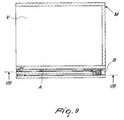
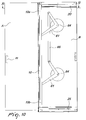
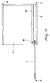
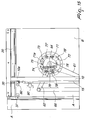
- the device 1 being considered is composed of an upright 10 constituted by a profile, in which the upper end 10a and the lower end 10b are rendered able to slide along the respective profile guides 20 and 25, which are fixed horizontally on the outer surface of the side of the internal space V to which a retractable door A is to be applied.
- the retractable door A and the device 1 being considered can be advantageously accommodated in a retraction compartment B, which is adjacent to the useful internal space V of the piece of furniture M and is completed by an outside wall, with the ceiling and footing of the same piece of furniture.
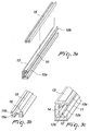
- the upright or profile 10 has an outer longitudinal groove thereof 11, with a longitudinal cavity that has a semicircular cross-section 12, and an inner longitudinal groove 12a, in addition to a lateral shoulder 13 thereof which is T-shaped.
- the profile 10 is furthermore provided with a wall or longitudinal rib 14 which forms an intermediate compartment 12b, which is open toward the semicircular cavity 12 due to the presence of the longitudinal groove 12a.
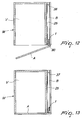
- the shoulder 13 of the upright 10 is designed to accommodate the internal compartment 15a of a profile 15 which is provided with a length that is slightly shorter than the length of the upright 10 and has double-C shape, having a compartment 15b which is arranged opposite the compartment 15a and is designed to accommodate the bases of a series of hinges 90, as specified better hereinafter.
- the compartment 15a of the profile 15 is designed to accommodate the shoulder 13 of the upright 10, after longitudinal sliding, in order to be adjusted and locked axially and transversely thereto, according to one of the methods of the already-known type and indicated by way of example with the fixing seat 16 in Figure 3 .
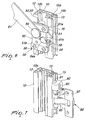
- the upright 10 is rendered able to slide along the guides 20 and 25 by interposition respectively of an upper carriage 30 and of a lower carriage 40, which are conveniently fixed respectively to its ends 10a and 10b.
- an upper carriage 30 is constituted by a plate 31 for supporting a pair of free pulleys 32-33, the plate 31 being provided with a stem 31a with a base plate 31 b on which a pair of screws 34 is rendered able to pass and is adapted to screw onto the threaded seat of at least one contrast plate 35.
- Such contrast plate 35 is accommodated in the compartment 12b of the end 10a of the upright 10 and is provided preferably with shoulders 35b which are adapted to be guided within the groove 12b of the upright 10. The screwing of the screws 34 therefore allows perfect locking of the carriage 30 in the correct position of the end 10a of the upright 10, such position being defined by a head shoulder of the contrast plate 35.
- the carriage 30 is naturally applied to the upper guide 20, accommodating the grooves of the pulleys 32-33 along the rail 21, so as to render it able to slide along the compartment 22 of the upper guide 20, which also inhibits its lateral escape in the presence of its perpendicular upper edge 23.
- the upper guide 20 is provided with a lower compartment 24, which allows the passage of the stroke limiting block 36, which is adapted to abut against an adapted abutment 37, in order to delimit the stopping point of the carriage 30 and therefore of the upright 10 and of the door A in the front part of the retraction compartment B.
- the upright 10 is also provided with a pair of devices 80 for preventing the retraction of the door A into the compartment B, which are actuated by the door A itself which acts on the circular rubber pad 83 of the elastic arm 81, to the opposite end of which a roller 82 is applied.
- the rollers 82 are pushed laterally into a compartment that is provided on the surface of the shoulder of the piece of furniture M, in order to prevent the unwanted retraction of the upright 10 into the retraction compartment B.
- a lower carriage 40 is constituted by a plate 41 for supporting a pair of free rollers 42-43, the plate 41 being provided with a substantially perpendicular stem 41a which is arranged in the compartment 12b of the upright 10 and is associated by means of at least one screw 44 with an external contrast plate 45, which is accommodated in the compartment 11 of the upright 10, for the correct locking of the carriage 40 to its end 10b.
- the lower carriage 40 is naturally applied to the lower guide 25, accommodating its rollers 42-43 along the guiding seat 27, which allows its stroke in depth within the retraction compartment B.
- the lower guide 25 is provided with an upper compartment 28, which allows the passage of the stroke limiting block 46, which is adapted to abut against an abutment 37, in order to delimit the stopping point of the carriage 40, therefore of the upright 10 and of the door A at the rear end of the retraction compartment B.
- a device 80 is provided for preventing the return of the door A into the compartment B, as specified above.
- the positioning and locking of the carriages 30-40 at the ends 10a-10b of the upright 10 allows a perfectly parallel arrangement in the stroke of the carriages 30-40 along the respective guides 20-25 at any time of its motion or positioning of the door A within the retraction compartment B.
- the semicylindrical cavity 12 of the upright 10 is designed to accommodate a pair of annular free wheels 52-53 of two carriages 50, which are inserted therein in the intermediate part of the upright 10, before applying and fixing the upper carriages 30 and/or the lower carriage 40 described so far.
- the intermediate carriages 50 are meant to ensure a dynamic connection of the upright 10, therefore of the door A integrally hinged thereto, with a respective end or arm 61 of a pair of rockers 60 which are described better hereinafter.
- an intermediate carriage 50 is constituted substantially by a plate 51 which, by means of adapted pivots (not shown), is adapted to support the pair of free wheels 52-53, which are accommodated in the semicylindrical cavity 12 of the upright 10, while a contrast plate 54 is guided therein and retained by a pair of lateral guides 51a-51b, which are joined to the base plate 51 for example by means of four screws 56.
- a pivot 59 is integrally applied to the contrast plate 54 and, through the possible interposition of bearings or bushings, hinges the end of an arm 61 of a rocker 60.
- the contrast plate 54 is provided with a nut or threaded protrusion 54a into which the stem of a screw 58 is screwed whose head is accommodated in a compartment 51 c of the base plate 51.
- the contrast plate 54 is forced to perform a translational motion along the guides 51a-51b, with a consequent transverse movement of the pivot 59 and of the end of the arm 61 of the rocker 60.
- By acting on the screw 58 of at least one of the carriages 50 it is thus possible to adjust and fix stably the perfect verticality of the door A and of its upright 10, both during retraction into the compartment B and during swing closure onto the useful internal space V of the piece of furniture M.
- the minimum and maximum length of the stroke of the contrast plate 54 is delimited by a pawl (not shown), which is integral with the plate 51 and can slide within a slot (55) of the contrast plate 54.
- a pair of rockers 60 is associated with the upright 10 by a corresponding number of carriages 50.
- Each rocker 60 is constituted not only by the arm 61 for oscillating connection, which can translate vertically, to the upright 10 by interposition of the respective carriage 50, but also by a second arm 62, which is rigidly connected to the other arm 61, in a position which is for example perpendicular, and is provided with its own oscillation pivot 64.
- each rocker 60 is preferably welded or in any case stably joined to a disk 63 which is coaxial to the pivot 64 and is designed for a possible application of a device for damping the opening and closing motion of the sliding door, as specified better hereinafter.
- the pivot 64 of both rockers 60 is associated stably with the outer surface of the shoulder of the piece of furniture that already supports the depth guides 20-25 within the retraction compartment B, allowing the oscillation of the rockers 60 by interposition, for example, of adapted bushings or bearings (not shown).
- the arms 62 of the two rockers 60 are mutually joined and pivoted by means of a distribution bar 66, which ensures a synchronized oscillation thereof, with respect to the positioning and pushing or pulling motion of the upright 10 and of the door A, along the guides 20 and 25, within the retraction compartment B.
- the sliding door or wing A is stably associated and hinged to the upright 10 by interposition of a portion of a profile 15 which is shaped like a double letter C, as exemplified in particular in Figure 3 , and the internal compartment 15a of which accommodates the crossmember of the profile 13 of the upright 10, after suitable adjustment and locking 16.
- the outer compartment 15b of the portion of profile 15 is designed to accommodate the base 91 of a series of hinges 90, each of which is locked in the chosen vertical position of the profile 15, with the closure and locking of at least one block 92, by means of at least one screw 93, against the outer surface of the profile 15 which is already rendered integral with the upright 10.
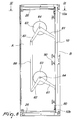
- a door A for closing the internal space V of the piece of furniture M is shown in its condition of full retraction within the compartment B of the piece of furniture M, in order to leave the useful internal space V completely open and accessible, being guided and retained therein in this condition by the device 1 being considered.
- the upright 10 In the retraction condition, the upright 10 is accommodated at the rear end of the compartment B, supported and guided vertically by its head carriages 30-40, which slide along the respective guides 20-25 and in turn supporting the door A by means of the series of hinges 90.
- the stable retention of the door A in its condition of full retraction within the compartment B is ensured by the presence of the two arms 61 of the two rockers 60, which can move along the upright 10, by means of the respective carriages 50, thus having their second arms 62, joined by the bar 66, synchronized in the oscillation of the rockers 60, maintaining the verticality of the upright 10 and therefore of the door A at all times of translation and positioning.
- the rotation of the arms 61 of course entails the rotation also of the perpendicular arms 62 of the two respective rockers 60, such rotation being necessarily synchronized due to the presence of the distribution bar 66 which is pivoted to the arms 62.
- the two arms 61 would rotate in a manner which is not synchronized and parallel, with a variation of their distance or center distance along the upright 10, so that the same door A might be extracted in an inclined form, then maintaining a lack of verticality with respect to the piece of furniture M.
- the function of the distribution bar 66 is indeed to always ensure the perfect balancing of the door A and of its upright 10, distributing on the upright 10 not only the cantilever weight of the door A, but also any irregular pulling or pushing motion of t door A moving within the compartment B.
- the device 1 applied to the lateral shoulder of the door A, allows a better utilization of the depth of the internal space V than all the other known solutions. Due to these constructive and functional characterizations, the device 1 being considered therefore allows the application to the piece of furniture M of retracting doors A that are provided as a single panel, even of considerable size and weight, without having to render them folding so that they can be accommodated in the retraction compartment B, with simplicity and safety, in accordance with the specified aim.
- Figures 12 and 13 show that the series of hinges 90 preferably applied to the piece of furniture M is of the double-lever type 95-96, with the result that when the door A is completely closed the door A can be superimposed on the shoulders of the lateral uprights of the piece of furniture M, ensuring their visual concealment, with a considerable aesthetic and visual advantage, in addition to being able to ensure the maximum extent of the useful volume of the piece of furniture M, in accordance with another one of the specified objects.
- the device 1 instead of being applied to the outer surface of the wall of the useful internal space V, can be applied to the internal surface of the outer wall of the retraction compartment B, thus arranging on such surface the guides 20-25 and the pivot 64 of the rockers 60, in addition to the optional box 72 of the damping system cited above and described better hereinafter.
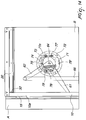
- the internal side of the disk 63 of at least one rocker 60 is provided with a surface in relief 71 which is cam-shaped and is oriented conveniently with respect to the position of the arms 61-62 of the rocker 60.
- the disk or cover 63 is rendered able to rotate on the raised edge of a box 72, which is fixed to the same outer surface of the useful internal space of the piece of furniture M where also the guides 20-25 are fixed and on the bottom of which the pivot 64 for the rotation of each rocker 60 is fixed.
- a pivot 73 is rigidly fixed on the bottom of the box 72, and the end of an arm 74 is pivoted, such arm being provided with a probe roller 75, the opposite end being associated with the end of one or more elastic means 76 whose opposite end is integral with the bottom of the box 72. Due to the traction force of the elastic means 76, the probe 75 is constantly placed in contact with the cam-like profile 71 of the cover 63 of the rocker 60.
- the base of the box 72 is also provided with a series of dampers or oil pressure-controlled braking devices 77, which act in contrast against a series of portions of circular rack 78 which are arranged in suitable grip positions.
- the elastic means 76 return the accumulated effort, pushing the door A toward the outlet of the compartment B. In the final part of the exit, the thrust force of the elastic means 76 is contrasted by the action of the dampers 77 on the racks 78.
- Figures 14-15 and 16 clearly shows that the device 1 being considered also allows a positive application of a damping device in the step of entry and exit of the door A from its retraction compartment B, in order to make the retraction even easier and safer in addition to further increasing its duration over time, in accordance with another one of the specified objects.
- the constructive solution of the device 1 described and illustrated so far can be changed and adapted to different conditions of use.
- the device 1 can also be applied to doors A that are made up of two or more wings which are mutually joined and rendered able to fold by hinges in order to be accommodated in a retraction compartment that must have an adequate width, and likewise it is possible to provide for the application of two mutually opposite retracting doors on the two sides or shoulders of a single piece of furniture.
Landscapes
- Engineering & Computer Science (AREA)
- Mechanical Engineering (AREA)
- Hinges (AREA)
- Cabinets, Racks, Or The Like Of Rigid Construction (AREA)
- Extensible Doors And Revolving Doors (AREA)
- Legs For Furniture In General (AREA)
Applications Claiming Priority (2)
| Application Number | Priority Date | Filing Date | Title |
|---|---|---|---|
| ITBL2010A000020A IT1402815B1 (it) | 2010-12-03 | 2010-12-03 | Dispositivo per l'applicazione di porte a scomparsa laterale, particolarmente per mobili |
| PCT/EP2011/071512 WO2012072738A1 (en) | 2010-12-03 | 2011-12-01 | Device for applying laterally retracting doors, particularly for pieces of furniture |
Publications (2)
| Publication Number | Publication Date |
|---|---|
| EP2655768A1 EP2655768A1 (en) | 2013-10-30 |
| EP2655768B1 true EP2655768B1 (en) | 2016-08-03 |
Family
ID=43736746
Family Applications (1)
| Application Number | Title | Priority Date | Filing Date |
|---|---|---|---|
| EP11790969.7A Active EP2655768B1 (en) | 2010-12-03 | 2011-12-01 | Device for applying laterally retracting doors, particularly for pieces of furniture |
Country Status (9)
| Country | Link |
|---|---|
| US (1) | US9057216B2 (ru) |
| EP (1) | EP2655768B1 (ru) |
| JP (1) | JP6006728B2 (ru) |
| CN (1) | CN103443378B (ru) |
| BR (1) | BR112013013053B1 (ru) |
| ES (1) | ES2602558T3 (ru) |
| IT (1) | IT1402815B1 (ru) |
| RU (1) | RU2567717C2 (ru) |
| WO (1) | WO2012072738A1 (ru) |
Families Citing this family (26)
| Publication number | Priority date | Publication date | Assignee | Title |
|---|---|---|---|---|
| US9976336B2 (en) * | 2014-07-11 | 2018-05-22 | B/E Aerospace, Inc. | Telescoping aircraft panel door |
| US9440727B2 (en) * | 2014-07-11 | 2016-09-13 | B/E Aerospace, Inc. | Telescoping aircraft panel door |
| AT516567B1 (de) * | 2014-11-26 | 2018-01-15 | Blum Gmbh Julius | Anordnung aus einer Möbeltüre und einem Hohlraum |
| US9598887B2 (en) * | 2015-02-18 | 2017-03-21 | Margaret B. Reed | Hidden hinge door system and method for use in residential and commercial buildings |
| CN108290635B (zh) * | 2015-10-14 | 2021-06-15 | B/E航空公司 | 飞机乘客套间隐私屏风控制设备及方法 |
| US9894996B1 (en) * | 2016-10-31 | 2018-02-20 | Larry Mitchell Grela | Cabinet |
| AT519246B1 (de) * | 2017-01-13 | 2018-05-15 | Blum Gmbh Julius | Führungssystem zur Führung eines bewegbar gelagerten Möbelteiles |
| AT519515B1 (de) * | 2017-01-13 | 2023-02-15 | Blum Gmbh Julius | Einrichtungsanordnung |
| DE102017104182A1 (de) * | 2017-02-28 | 2018-08-30 | ambigence GmbH & Co. KG | Möbel |
| DE102017104181A1 (de) * | 2017-02-28 | 2018-08-30 | ambigence GmbH & Co. KG | Möbel |
| AT519903B1 (de) * | 2017-05-11 | 2022-09-15 | Blum Gmbh Julius | Schiene zur Führung eines Schlittens einer Möbeltüre |
| IT201700078326A1 (it) * | 2017-07-12 | 2019-01-12 | Bortoluzzi Sistemi Spa | “mobile con ante scorrevoli e ripiegabili a scomparsa” |
| CN107461097B (zh) * | 2017-09-01 | 2022-11-18 | 广东东泰五金精密制造有限公司 | 一种家具推拉门的转动轮弹性活动结构 |
| WO2019106508A1 (en) * | 2017-11-28 | 2019-06-06 | Bortoluzzi Sistemi S.P.A. | Servomechanism for furniture leaf |
| CN108060848B (zh) * | 2018-01-05 | 2023-08-15 | 广东东泰五金精密制造有限公司 | 一种家具回转开闭锁定结构 |
| DE102018100674B4 (de) * | 2018-01-12 | 2020-03-05 | Hettich-Oni Gmbh & Co. Kg | Möbelplatte mit einem Scharnier und Möbel mit einer derartigen Möbelplatte |
| PL3569806T3 (pl) * | 2018-05-17 | 2022-01-17 | Kesseböhmer Holding Kg | Okucie frontowe do uchylnego mocowania frontu meblowego na korpusie meblowym |
| DE102018120661A1 (de) * | 2018-08-23 | 2020-02-27 | ambigence GmbH & Co. KG | Möbelkomponente und Verfahren zur Herstellung |
| AT521133B1 (de) * | 2018-11-14 | 2019-11-15 | Blum Gmbh Julius | Führungssystem zur Führung eines bewegbar gelagerten Türflügels |
| AT521365B1 (de) | 2018-12-20 | 2020-01-15 | Blum Gmbh Julius | Führungssystem zur Führung wenigstens eines bewegbar gelagerten Türflügels |
| EP3980619B1 (de) * | 2019-06-07 | 2023-09-13 | Hawa Sliding Solutions AG | Möbelstück mit einer von einer verschiebevorrichtung gehaltenen tür |
| AT17257U1 (de) * | 2019-12-19 | 2021-10-15 | Blum Gmbh Julius | Verfahren zur Montage einer Führungsanordnung für ein bewegbares Möbelteil |
| AT523270B1 (de) * | 2019-12-19 | 2021-07-15 | Blum Gmbh Julius | Anordnung zur Führung einer Schiebetür oder Falt-Schiebetür |
| CN111749584A (zh) * | 2020-06-19 | 2020-10-09 | 广东威法定制家居股份有限公司 | 侧推隐藏门连接装置及置物柜 |
| AT524324B1 (de) * | 2020-12-17 | 2022-05-15 | Blum Gmbh Julius | Lagerungsvorrichtung zur Lagerung wenigstens eines Türflügels |
| EP4269735A1 (en) * | 2022-03-22 | 2023-11-01 | Griffo, Cristofaro | Double-sided door with integrated universal hinge |
Family Cites Families (49)
| Publication number | Priority date | Publication date | Assignee | Title |
|---|---|---|---|---|
| US245605A (en) * | 1881-08-16 | Door-hanger | ||
| US423280A (en) * | 1890-03-11 | Door-hanger | ||
| US352906A (en) * | 1886-11-23 | James allan | ||
| US511208A (en) * | 1893-12-19 | Sliding-door hanger | ||
| US374859A (en) * | 1887-12-13 | Sliding-door hanger | ||
| US863286A (en) * | 1905-07-21 | 1907-08-13 | James L Kershaw | Sectional bookcase. |
| US899049A (en) * | 1908-01-27 | 1908-09-22 | Frederick Joseph Honor | Bookcase. |
| US972412A (en) * | 1909-08-04 | 1910-10-11 | Maurice Taussig | Disappearing door. |
| US984793A (en) * | 1909-10-05 | 1911-02-21 | Frank Olander | Equalizer. |
| US1348680A (en) * | 1918-09-17 | 1920-08-03 | Solomon Himmel | Door-equalizer |
| US1513849A (en) * | 1923-07-25 | 1924-11-04 | Mortimer H Moore | Safe |
| US1720050A (en) * | 1928-03-27 | 1929-07-09 | Grand Rapids Store Equip Co | Disappearing door structure |
| US1930547A (en) * | 1930-06-07 | 1933-10-17 | Lyon Metal Products Inc | Cabinet construction |
| US1909849A (en) * | 1931-03-17 | 1933-05-16 | Remington Rand Inc | Door mounting for safes |
| US1933904A (en) * | 1931-05-16 | 1933-11-07 | Miles W Hawks | Garage door operating mechanism |
| US2632926A (en) * | 1950-08-14 | 1953-03-31 | Dowlong Mfg Co | Sliding door and hardware therefor |
| US2709029A (en) * | 1952-11-12 | 1955-05-24 | Paul F Nockels | Packaging machine for cartons |
| US2774644A (en) * | 1954-02-15 | 1956-12-18 | Ray A Patterson | Drawer and stabilizing means therefor |
| US3359684A (en) * | 1965-08-02 | 1967-12-26 | Dura Corp | Actuator with fixed pivot |
| US3456995A (en) * | 1967-04-11 | 1969-07-22 | Gen Electric | Slide-in cabinet door |
| US3570579A (en) * | 1968-03-18 | 1971-03-16 | Nippon Musical Instruments Mfg | Sliding cover and housing device thereof |
| US3724133A (en) * | 1970-04-03 | 1973-04-03 | Nippon Denso Co | Means for opening and closing a window assembly of a vehicle |
| DE2263073C2 (de) * | 1972-12-22 | 1982-11-25 | Robert Krause KG Zweigniederlassung Weilheim/Teck, 7315 Weilheim | Ausziehbeschlag für eine erste Platte und eine zweite Platte, wie einer Tisch- oder Arbeitsplatte |
| JPH021427Y2 (ru) * | 1981-02-02 | 1990-01-12 | ||
| CH670224A5 (ru) * | 1983-04-20 | 1989-05-31 | Cwa Const Sa | |
| JPS6219112A (ja) * | 1985-07-19 | 1987-01-27 | 大建工業株式会社 | 収納装置 |
| CH670555A5 (ru) * | 1986-07-02 | 1989-06-30 | Karl Haab | |
| AT392321B (de) * | 1986-10-16 | 1991-03-11 | Alfit Gmbh | Beschlag fuer mit schwenk-schiebetueren ausgestattete kastenmoebel u. dgl. |
| US4729612A (en) * | 1987-02-27 | 1988-03-08 | Stone Allen F | Hinge support system |
| US4821375A (en) * | 1988-01-29 | 1989-04-18 | Viking Metal Cabinet Co., Inc. | Recessing hinge mechanism |
| US4976502A (en) * | 1989-04-25 | 1990-12-11 | Herman Miller, Inc. | Cabinet with pocketing doors |
| US5078461A (en) * | 1989-04-25 | 1992-01-07 | Herman Miller, Inc. | Cabinet with pocketing doors |
| DD297317A5 (de) * | 1989-03-14 | 1992-01-09 | Karl Haab Und Otto Haab,Ch | Moebelstueck mit versenkbarer tuere |
| DE59003645D1 (de) * | 1989-03-14 | 1994-01-13 | Karl Haab | Möbelstück mit versenkbarer Türe. |
| US4974912A (en) * | 1989-04-05 | 1990-12-04 | Standard Precision, Inc. | Pocket door suspension system |
| FR2651530A1 (fr) | 1989-09-07 | 1991-03-08 | Azoulay Benjamin | Porte coulissante suspendue escamotable. |
| IT1259209B (it) | 1992-04-02 | 1996-03-11 | Armadio con ante pieghevoli e scorrevoli a scomparsa | |
| JP2518473Y2 (ja) * | 1992-11-18 | 1996-11-27 | 高橋金物株式会社 | 垂直型フリッパードアの取付構造 |
| JP2593774Y2 (ja) * | 1993-12-29 | 1999-04-12 | スガツネ工業株式会社 | フリッパー扉を有するキャビネット |
| CH693070A5 (de) * | 1998-02-02 | 2003-02-14 | Hawa Ag | Befestigungsvorrichtung einer faltbaren Tür. |
| DE29808185U1 (de) * | 1998-05-06 | 1998-08-27 | Salice Arturo Spa | Möbel mit einem durch eine zweiflügelige Faltschiebetür verschließbaren Korpusteil |
| US6994410B2 (en) * | 2002-09-10 | 2006-02-07 | Knape & Vogt Manufacturing Co. | Pocket door slide |
| DE102005020440A1 (de) * | 2005-04-29 | 2006-11-09 | Glasbau Hahn Gmbh + Co. Kg | Vitrine zur Aufbewahrung und/oder Zurschaustellung von Gegenständen |
| ITMI20060943A1 (it) * | 2006-05-12 | 2007-11-13 | System Holz Spa | Nessuno |
| ITMI20061214A1 (it) * | 2006-06-23 | 2007-12-24 | Dada S P A | Armadio o mobile similare con sportelli pieghevoli e scorrevoli a scomparsa |
| US20080218043A1 (en) * | 2006-11-15 | 2008-09-11 | Angelo Gianelo | Drawer guidance mechanism |
| US20080297015A1 (en) * | 2007-05-30 | 2008-12-04 | Steelcase Inc. | Storage unit back stop and method |
| EP2527576B1 (de) * | 2009-04-28 | 2014-07-16 | Hawa Ag | Scharnier insbesondere für eine Verschiebevorrichtung |
| DE202011002810U1 (de) * | 2011-02-16 | 2011-06-09 | Inter Ikea Systems B.V. | Mechanismus für Schiebetür |
-
2010
- 2010-12-03 IT ITBL2010A000020A patent/IT1402815B1/it active
-
2011
- 2011-12-01 US US13/884,400 patent/US9057216B2/en active Active
- 2011-12-01 EP EP11790969.7A patent/EP2655768B1/en active Active
- 2011-12-01 JP JP2013541351A patent/JP6006728B2/ja active Active
- 2011-12-01 ES ES11790969.7T patent/ES2602558T3/es active Active
- 2011-12-01 RU RU2013130228/12A patent/RU2567717C2/ru active
- 2011-12-01 WO PCT/EP2011/071512 patent/WO2012072738A1/en active Application Filing
- 2011-12-01 BR BR112013013053A patent/BR112013013053B1/pt active IP Right Grant
- 2011-12-01 CN CN201180057854.8A patent/CN103443378B/zh active Active
Also Published As
| Publication number | Publication date |
|---|---|
| IT1402815B1 (it) | 2013-09-27 |
| ITBL20100020A1 (it) | 2012-06-04 |
| CN103443378B (zh) | 2015-09-09 |
| JP6006728B2 (ja) | 2016-10-12 |
| BR112013013053A2 (pt) | 2016-08-09 |
| RU2567717C2 (ru) | 2015-11-10 |
| US20130232878A1 (en) | 2013-09-12 |
| ES2602558T3 (es) | 2017-02-21 |
| EP2655768A1 (en) | 2013-10-30 |
| RU2013130228A (ru) | 2015-01-10 |
| JP2014500417A (ja) | 2014-01-09 |
| WO2012072738A1 (en) | 2012-06-07 |
| CN103443378A (zh) | 2013-12-11 |
| US9057216B2 (en) | 2015-06-16 |
| BR112013013053B1 (pt) | 2020-04-14 |
Similar Documents
| Publication | Publication Date | Title |
|---|---|---|
| EP2655768B1 (en) | Device for applying laterally retracting doors, particularly for pieces of furniture | |
| JP2014500417A5 (ru) | ||
| US8763205B2 (en) | Running gear arrangement having a guide rail for a sliding door | |
| EP2167769B1 (en) | Mechanism for the aligned closure of sliding doors, in particular for units of furniture or compartments with two or more doors | |
| US8671633B2 (en) | Foldable sliding wall and carriage | |
| TWI665372B (zh) | 用於家具部件的引導系統 | |
| AU2012223029B2 (en) | Sectional door particularly for garage | |
| EP2032791B1 (en) | Cabinet or similar article of furniture with a sliding foldaway door | |
| FI84289C (fi) | Monteringsanordning foer en foenster- eller doerrhalva eller motsvarande. | |
| EP2021567B1 (en) | Hanging cabinet with overturning doors | |
| NO174976B (no) | Svingbar innglassingskonstruksjon for altaner | |
| CN108301718B (zh) | 一种回转推拉开闭家具的调节机构 | |
| US2577884A (en) | Folding door | |
| RU2600922C2 (ru) | Фурнитура для створки окна или двери, отставляемой в положении, по меньшей мере приближённом к параллельному, и горизонтально перемещаемой в этом параллельно-отставленном положении | |
| TW201829897A (zh) | 用於門扇的引導系統 | |
| CA2162176C (en) | Sliding door or sliding window system | |
| RU2547647C2 (ru) | Фурнитура для сдвижной створки окна или двери | |
| US6243988B1 (en) | Actuating device for a closing element movable in a vertical direction | |
| EP2801686B1 (en) | Opening ddevice for coplanar doors | |
| IT201900009945A1 (it) | Cerniera a scomparsa regolabile per serramenti | |
| JPS61282575A (ja) | 垂直移動窓 | |
| JP3538577B2 (ja) | 吊支式引戸装置における引戸の移動規制装置 | |
| RU2187614C1 (ru) | Устройство для навешивания створок дверей и окон | |
| IT201900002052U1 (it) | Cerniera a scomparsa regolabile per serramenti |
Legal Events
| Date | Code | Title | Description |
|---|---|---|---|
| PUAI | Public reference made under article 153(3) epc to a published international application that has entered the european phase |
Free format text: ORIGINAL CODE: 0009012 |
|
| 17P | Request for examination filed |
Effective date: 20130605 |
|
| AK | Designated contracting states |
Kind code of ref document: A1 Designated state(s): AL AT BE BG CH CY CZ DE DK EE ES FI FR GB GR HR HU IE IS IT LI LT LU LV MC MK MT NL NO PL PT RO RS SE SI SK SM TR |
|
| RIN1 | Information on inventor provided before grant (corrected) |
Inventor name: GIROTTO, ADRIANO Inventor name: BORTOLUZZI, GUIDO |
|
| DAX | Request for extension of the european patent (deleted) | ||
| 17Q | First examination report despatched |
Effective date: 20150512 |
|
| RAP1 | Party data changed (applicant data changed or rights of an application transferred) |
Owner name: BORTOLUZZI SISTEMI S.P.A. |
|
| GRAP | Despatch of communication of intention to grant a patent |
Free format text: ORIGINAL CODE: EPIDOSNIGR1 |
|
| INTG | Intention to grant announced |
Effective date: 20160218 |
|
| GRAS | Grant fee paid |
Free format text: ORIGINAL CODE: EPIDOSNIGR3 |
|
| GRAA | (expected) grant |
Free format text: ORIGINAL CODE: 0009210 |
|
| AK | Designated contracting states |
Kind code of ref document: B1 Designated state(s): AL AT BE BG CH CY CZ DE DK EE ES FI FR GB GR HR HU IE IS IT LI LT LU LV MC MK MT NL NO PL PT RO RS SE SI SK SM TR |
|
| REG | Reference to a national code |
Ref country code: GB Ref legal event code: FG4D |
|
| REG | Reference to a national code |
Ref country code: CH Ref legal event code: EP Ref country code: AT Ref legal event code: REF Ref document number: 817461 Country of ref document: AT Kind code of ref document: T Effective date: 20160815 |
|
| REG | Reference to a national code |
Ref country code: IE Ref legal event code: FG4D |
|
| REG | Reference to a national code |
Ref country code: DE Ref legal event code: R096 Ref document number: 602011028845 Country of ref document: DE |
|
| REG | Reference to a national code |
Ref country code: FR Ref legal event code: PLFP Year of fee payment: 6 |
|
| REG | Reference to a national code |
Ref country code: NL Ref legal event code: MP Effective date: 20160803 |
|
| REG | Reference to a national code |
Ref country code: LT Ref legal event code: MG4D |
|
| REG | Reference to a national code |
Ref country code: AT Ref legal event code: MK05 Ref document number: 817461 Country of ref document: AT Kind code of ref document: T Effective date: 20160803 |
|
| PG25 | Lapsed in a contracting state [announced via postgrant information from national office to epo] |
Ref country code: IS Free format text: LAPSE BECAUSE OF FAILURE TO SUBMIT A TRANSLATION OF THE DESCRIPTION OR TO PAY THE FEE WITHIN THE PRESCRIBED TIME-LIMIT Effective date: 20161203 Ref country code: HR Free format text: LAPSE BECAUSE OF FAILURE TO SUBMIT A TRANSLATION OF THE DESCRIPTION OR TO PAY THE FEE WITHIN THE PRESCRIBED TIME-LIMIT Effective date: 20160803 Ref country code: NL Free format text: LAPSE BECAUSE OF FAILURE TO SUBMIT A TRANSLATION OF THE DESCRIPTION OR TO PAY THE FEE WITHIN THE PRESCRIBED TIME-LIMIT Effective date: 20160803 Ref country code: RS Free format text: LAPSE BECAUSE OF FAILURE TO SUBMIT A TRANSLATION OF THE DESCRIPTION OR TO PAY THE FEE WITHIN THE PRESCRIBED TIME-LIMIT Effective date: 20160803 Ref country code: NO Free format text: LAPSE BECAUSE OF FAILURE TO SUBMIT A TRANSLATION OF THE DESCRIPTION OR TO PAY THE FEE WITHIN THE PRESCRIBED TIME-LIMIT Effective date: 20161103 Ref country code: FI Free format text: LAPSE BECAUSE OF FAILURE TO SUBMIT A TRANSLATION OF THE DESCRIPTION OR TO PAY THE FEE WITHIN THE PRESCRIBED TIME-LIMIT Effective date: 20160803 Ref country code: LT Free format text: LAPSE BECAUSE OF FAILURE TO SUBMIT A TRANSLATION OF THE DESCRIPTION OR TO PAY THE FEE WITHIN THE PRESCRIBED TIME-LIMIT Effective date: 20160803 |
|
| REG | Reference to a national code |
Ref country code: ES Ref legal event code: FG2A Ref document number: 2602558 Country of ref document: ES Kind code of ref document: T3 Effective date: 20170221 |
|
| PG25 | Lapsed in a contracting state [announced via postgrant information from national office to epo] |
Ref country code: AT Free format text: LAPSE BECAUSE OF FAILURE TO SUBMIT A TRANSLATION OF THE DESCRIPTION OR TO PAY THE FEE WITHIN THE PRESCRIBED TIME-LIMIT Effective date: 20160803 Ref country code: GR Free format text: LAPSE BECAUSE OF FAILURE TO SUBMIT A TRANSLATION OF THE DESCRIPTION OR TO PAY THE FEE WITHIN THE PRESCRIBED TIME-LIMIT Effective date: 20161104 Ref country code: PT Free format text: LAPSE BECAUSE OF FAILURE TO SUBMIT A TRANSLATION OF THE DESCRIPTION OR TO PAY THE FEE WITHIN THE PRESCRIBED TIME-LIMIT Effective date: 20161205 Ref country code: PL Free format text: LAPSE BECAUSE OF FAILURE TO SUBMIT A TRANSLATION OF THE DESCRIPTION OR TO PAY THE FEE WITHIN THE PRESCRIBED TIME-LIMIT Effective date: 20160803 Ref country code: LV Free format text: LAPSE BECAUSE OF FAILURE TO SUBMIT A TRANSLATION OF THE DESCRIPTION OR TO PAY THE FEE WITHIN THE PRESCRIBED TIME-LIMIT Effective date: 20160803 Ref country code: SE Free format text: LAPSE BECAUSE OF FAILURE TO SUBMIT A TRANSLATION OF THE DESCRIPTION OR TO PAY THE FEE WITHIN THE PRESCRIBED TIME-LIMIT Effective date: 20160803 |
|
| PG25 | Lapsed in a contracting state [announced via postgrant information from national office to epo] |
Ref country code: EE Free format text: LAPSE BECAUSE OF FAILURE TO SUBMIT A TRANSLATION OF THE DESCRIPTION OR TO PAY THE FEE WITHIN THE PRESCRIBED TIME-LIMIT Effective date: 20160803 Ref country code: RO Free format text: LAPSE BECAUSE OF FAILURE TO SUBMIT A TRANSLATION OF THE DESCRIPTION OR TO PAY THE FEE WITHIN THE PRESCRIBED TIME-LIMIT Effective date: 20160803 |
|
| REG | Reference to a national code |
Ref country code: DE Ref legal event code: R097 Ref document number: 602011028845 Country of ref document: DE |
|
| PG25 | Lapsed in a contracting state [announced via postgrant information from national office to epo] |
Ref country code: BE Free format text: LAPSE BECAUSE OF FAILURE TO SUBMIT A TRANSLATION OF THE DESCRIPTION OR TO PAY THE FEE WITHIN THE PRESCRIBED TIME-LIMIT Effective date: 20160803 Ref country code: DK Free format text: LAPSE BECAUSE OF FAILURE TO SUBMIT A TRANSLATION OF THE DESCRIPTION OR TO PAY THE FEE WITHIN THE PRESCRIBED TIME-LIMIT Effective date: 20160803 Ref country code: SM Free format text: LAPSE BECAUSE OF FAILURE TO SUBMIT A TRANSLATION OF THE DESCRIPTION OR TO PAY THE FEE WITHIN THE PRESCRIBED TIME-LIMIT Effective date: 20160803 Ref country code: SK Free format text: LAPSE BECAUSE OF FAILURE TO SUBMIT A TRANSLATION OF THE DESCRIPTION OR TO PAY THE FEE WITHIN THE PRESCRIBED TIME-LIMIT Effective date: 20160803 Ref country code: CZ Free format text: LAPSE BECAUSE OF FAILURE TO SUBMIT A TRANSLATION OF THE DESCRIPTION OR TO PAY THE FEE WITHIN THE PRESCRIBED TIME-LIMIT Effective date: 20160803 Ref country code: BG Free format text: LAPSE BECAUSE OF FAILURE TO SUBMIT A TRANSLATION OF THE DESCRIPTION OR TO PAY THE FEE WITHIN THE PRESCRIBED TIME-LIMIT Effective date: 20161103 |
|
| PLBE | No opposition filed within time limit |
Free format text: ORIGINAL CODE: 0009261 |
|
| STAA | Information on the status of an ep patent application or granted ep patent |
Free format text: STATUS: NO OPPOSITION FILED WITHIN TIME LIMIT |
|
| 26N | No opposition filed |
Effective date: 20170504 |
|
| REG | Reference to a national code |
Ref country code: CH Ref legal event code: PL |
|
| PG25 | Lapsed in a contracting state [announced via postgrant information from national office to epo] |
Ref country code: SI Free format text: LAPSE BECAUSE OF FAILURE TO SUBMIT A TRANSLATION OF THE DESCRIPTION OR TO PAY THE FEE WITHIN THE PRESCRIBED TIME-LIMIT Effective date: 20160803 |
|
| PG25 | Lapsed in a contracting state [announced via postgrant information from national office to epo] |
Ref country code: MC Free format text: LAPSE BECAUSE OF FAILURE TO SUBMIT A TRANSLATION OF THE DESCRIPTION OR TO PAY THE FEE WITHIN THE PRESCRIBED TIME-LIMIT Effective date: 20160803 |
|
| REG | Reference to a national code |
Ref country code: IE Ref legal event code: MM4A |
|
| PG25 | Lapsed in a contracting state [announced via postgrant information from national office to epo] |
Ref country code: LU Free format text: LAPSE BECAUSE OF NON-PAYMENT OF DUE FEES Effective date: 20161201 Ref country code: LI Free format text: LAPSE BECAUSE OF NON-PAYMENT OF DUE FEES Effective date: 20161231 Ref country code: CH Free format text: LAPSE BECAUSE OF NON-PAYMENT OF DUE FEES Effective date: 20161231 |
|
| REG | Reference to a national code |
Ref country code: FR Ref legal event code: PLFP Year of fee payment: 7 |
|
| PG25 | Lapsed in a contracting state [announced via postgrant information from national office to epo] |
Ref country code: IE Free format text: LAPSE BECAUSE OF NON-PAYMENT OF DUE FEES Effective date: 20161201 |
|
| PG25 | Lapsed in a contracting state [announced via postgrant information from national office to epo] |
Ref country code: CY Free format text: LAPSE BECAUSE OF FAILURE TO SUBMIT A TRANSLATION OF THE DESCRIPTION OR TO PAY THE FEE WITHIN THE PRESCRIBED TIME-LIMIT Effective date: 20160803 Ref country code: HU Free format text: LAPSE BECAUSE OF FAILURE TO SUBMIT A TRANSLATION OF THE DESCRIPTION OR TO PAY THE FEE WITHIN THE PRESCRIBED TIME-LIMIT; INVALID AB INITIO Effective date: 20111201 |
|
| PG25 | Lapsed in a contracting state [announced via postgrant information from national office to epo] |
Ref country code: MK Free format text: LAPSE BECAUSE OF FAILURE TO SUBMIT A TRANSLATION OF THE DESCRIPTION OR TO PAY THE FEE WITHIN THE PRESCRIBED TIME-LIMIT Effective date: 20160803 |
|
| PG25 | Lapsed in a contracting state [announced via postgrant information from national office to epo] |
Ref country code: MT Free format text: LAPSE BECAUSE OF NON-PAYMENT OF DUE FEES Effective date: 20161201 |
|
| PG25 | Lapsed in a contracting state [announced via postgrant information from national office to epo] |
Ref country code: AL Free format text: LAPSE BECAUSE OF FAILURE TO SUBMIT A TRANSLATION OF THE DESCRIPTION OR TO PAY THE FEE WITHIN THE PRESCRIBED TIME-LIMIT Effective date: 20160803 |
|
| REG | Reference to a national code |
Ref country code: DE Ref legal event code: R082 Ref document number: 602011028845 Country of ref document: DE Representative=s name: SCHIEBER - FARAGO PATENTANWAELTE, DE Ref country code: DE Ref legal event code: R082 Ref document number: 602011028845 Country of ref document: DE Representative=s name: FARAGO PATENTANWALTSGESELLSCHAFT MBH, DE |
|
| REG | Reference to a national code |
Ref country code: DE Ref legal event code: R082 Ref document number: 602011028845 Country of ref document: DE Representative=s name: SCHIEBER - FARAGO PATENTANWAELTE, DE |
|
| PGFP | Annual fee paid to national office [announced via postgrant information from national office to epo] |
Ref country code: IT Payment date: 20221122 Year of fee payment: 12 |
|
| PGFP | Annual fee paid to national office [announced via postgrant information from national office to epo] |
Ref country code: ES Payment date: 20230102 Year of fee payment: 12 |
|
| P01 | Opt-out of the competence of the unified patent court (upc) registered |
Effective date: 20230515 |
|
| PGFP | Annual fee paid to national office [announced via postgrant information from national office to epo] |
Ref country code: GB Payment date: 20231121 Year of fee payment: 13 |
|
| PGFP | Annual fee paid to national office [announced via postgrant information from national office to epo] |
Ref country code: TR Payment date: 20231123 Year of fee payment: 13 Ref country code: FR Payment date: 20231122 Year of fee payment: 13 Ref country code: DE Payment date: 20231121 Year of fee payment: 13 |
|
| PGFP | Annual fee paid to national office [announced via postgrant information from national office to epo] |
Ref country code: ES Payment date: 20240102 Year of fee payment: 13 |