EP2654825B1 - Cassettes de fluide médical et systèmes et procédés afférents - Google Patents
Cassettes de fluide médical et systèmes et procédés afférents Download PDFInfo
- Publication number
- EP2654825B1 EP2654825B1 EP11808070.4A EP11808070A EP2654825B1 EP 2654825 B1 EP2654825 B1 EP 2654825B1 EP 11808070 A EP11808070 A EP 11808070A EP 2654825 B1 EP2654825 B1 EP 2654825B1
- Authority
- EP
- European Patent Office
- Prior art keywords
- cassette
- actuator
- membrane
- medical fluid
- dome
- Prior art date
- Legal status (The legal status is an assumption and is not a legal conclusion. Google has not performed a legal analysis and makes no representation as to the accuracy of the status listed.)
- Active
Links
- 239000012530 fluid Substances 0.000 title claims description 220
- 238000000034 method Methods 0.000 title description 21
- 239000012528 membrane Substances 0.000 claims description 163
- 238000005086 pumping Methods 0.000 claims description 62
- 230000005291 magnetic effect Effects 0.000 claims description 56
- 239000000696 magnetic material Substances 0.000 claims description 8
- 210000004379 membrane Anatomy 0.000 description 156
- 239000000385 dialysis solution Substances 0.000 description 66
- -1 polyoxymethylene Polymers 0.000 description 61
- 239000004743 Polypropylene Substances 0.000 description 57
- 229920001155 polypropylene Polymers 0.000 description 57
- 229910000831 Steel Inorganic materials 0.000 description 26
- 239000010959 steel Substances 0.000 description 26
- 239000000463 material Substances 0.000 description 25
- 238000010168 coupling process Methods 0.000 description 17
- 238000000502 dialysis Methods 0.000 description 16
- 230000037361 pathway Effects 0.000 description 16
- 230000008878 coupling Effects 0.000 description 15
- 238000005859 coupling reaction Methods 0.000 description 15
- 239000008280 blood Substances 0.000 description 11
- 210000004369 blood Anatomy 0.000 description 11
- 239000010935 stainless steel Substances 0.000 description 11
- 229910001220 stainless steel Inorganic materials 0.000 description 11
- 238000002716 delivery method Methods 0.000 description 10
- 229920001343 polytetrafluoroethylene Polymers 0.000 description 9
- 239000004810 polytetrafluoroethylene Substances 0.000 description 9
- 230000007423 decrease Effects 0.000 description 8
- 239000000560 biocompatible material Substances 0.000 description 7
- 238000010276 construction Methods 0.000 description 6
- 230000007246 mechanism Effects 0.000 description 6
- 229910052751 metal Inorganic materials 0.000 description 6
- 239000002184 metal Substances 0.000 description 6
- 150000002739 metals Chemical class 0.000 description 6
- 238000000576 coating method Methods 0.000 description 5
- XEEYBQQBJWHFJM-UHFFFAOYSA-N Iron Chemical compound [Fe] XEEYBQQBJWHFJM-UHFFFAOYSA-N 0.000 description 4
- 239000011248 coating agent Substances 0.000 description 4
- DDRJAANPRJIHGJ-UHFFFAOYSA-N creatinine Chemical compound CN1CC(=O)NC1=N DDRJAANPRJIHGJ-UHFFFAOYSA-N 0.000 description 4
- 238000001631 haemodialysis Methods 0.000 description 4
- 230000000322 hemodialysis Effects 0.000 description 4
- 210000003200 peritoneal cavity Anatomy 0.000 description 4
- 230000002829 reductive effect Effects 0.000 description 4
- 239000011347 resin Substances 0.000 description 4
- 229920005989 resin Polymers 0.000 description 4
- 230000004044 response Effects 0.000 description 4
- 210000001015 abdomen Anatomy 0.000 description 3
- 229920000249 biocompatible polymer Polymers 0.000 description 3
- 230000006835 compression Effects 0.000 description 3
- 238000007906 compression Methods 0.000 description 3
- 230000003247 decreasing effect Effects 0.000 description 3
- 239000003302 ferromagnetic material Substances 0.000 description 3
- 238000001746 injection moulding Methods 0.000 description 3
- 238000009434 installation Methods 0.000 description 3
- 230000013011 mating Effects 0.000 description 3
- 239000003973 paint Substances 0.000 description 3
- 210000004303 peritoneum Anatomy 0.000 description 3
- 229920000515 polycarbonate Polymers 0.000 description 3
- 239000004417 polycarbonate Substances 0.000 description 3
- 239000004800 polyvinyl chloride Substances 0.000 description 3
- 229920000915 polyvinyl chloride Polymers 0.000 description 3
- 230000000717 retained effect Effects 0.000 description 3
- 229920004943 Delrin® Polymers 0.000 description 2
- DGAQECJNVWCQMB-PUAWFVPOSA-M Ilexoside XXIX Chemical compound C[C@@H]1CC[C@@]2(CC[C@@]3(C(=CC[C@H]4[C@]3(CC[C@@H]5[C@@]4(CC[C@@H](C5(C)C)OS(=O)(=O)[O-])C)C)[C@@H]2[C@]1(C)O)C)C(=O)O[C@H]6[C@@H]([C@H]([C@@H]([C@H](O6)CO)O)O)O.[Na+] DGAQECJNVWCQMB-PUAWFVPOSA-M 0.000 description 2
- PXHVJJICTQNCMI-UHFFFAOYSA-N Nickel Chemical compound [Ni] PXHVJJICTQNCMI-UHFFFAOYSA-N 0.000 description 2
- 229930040373 Paraformaldehyde Natural products 0.000 description 2
- 239000004696 Poly ether ether ketone Substances 0.000 description 2
- XSQUKJJJFZCRTK-UHFFFAOYSA-N Urea Chemical compound NC(N)=O XSQUKJJJFZCRTK-UHFFFAOYSA-N 0.000 description 2
- 238000004026 adhesive bonding Methods 0.000 description 2
- 229910052782 aluminium Inorganic materials 0.000 description 2
- XAGFODPZIPBFFR-UHFFFAOYSA-N aluminium Chemical compound [Al] XAGFODPZIPBFFR-UHFFFAOYSA-N 0.000 description 2
- JUPQTSLXMOCDHR-UHFFFAOYSA-N benzene-1,4-diol;bis(4-fluorophenyl)methanone Chemical compound OC1=CC=C(O)C=C1.C1=CC(F)=CC=C1C(=O)C1=CC=C(F)C=C1 JUPQTSLXMOCDHR-UHFFFAOYSA-N 0.000 description 2
- 239000004202 carbamide Substances 0.000 description 2
- 150000001875 compounds Chemical class 0.000 description 2
- 229940109239 creatinine Drugs 0.000 description 2
- 238000009792 diffusion process Methods 0.000 description 2
- PCHJSUWPFVWCPO-UHFFFAOYSA-N gold Chemical compound [Au] PCHJSUWPFVWCPO-UHFFFAOYSA-N 0.000 description 2
- 239000010931 gold Substances 0.000 description 2
- 229910052737 gold Inorganic materials 0.000 description 2
- 230000002401 inhibitory effect Effects 0.000 description 2
- 239000007924 injection Substances 0.000 description 2
- 238000002347 injection Methods 0.000 description 2
- 229910052742 iron Inorganic materials 0.000 description 2
- 238000003754 machining Methods 0.000 description 2
- 239000004033 plastic Substances 0.000 description 2
- 229920003023 plastic Polymers 0.000 description 2
- 229920000052 poly(p-xylylene) Polymers 0.000 description 2
- 229920002492 poly(sulfone) Polymers 0.000 description 2
- 229920002530 polyetherether ketone Polymers 0.000 description 2
- 229920000642 polymer Polymers 0.000 description 2
- 229920006324 polyoxymethylene Polymers 0.000 description 2
- 230000008569 process Effects 0.000 description 2
- 229910052708 sodium Inorganic materials 0.000 description 2
- 239000011734 sodium Substances 0.000 description 2
- 239000000243 solution Substances 0.000 description 2
- 229920006132 styrene block copolymer Polymers 0.000 description 2
- 239000000126 substance Substances 0.000 description 2
- 229920002725 thermoplastic elastomer Polymers 0.000 description 2
- 239000002699 waste material Substances 0.000 description 2
- XLYOFNOQVPJJNP-UHFFFAOYSA-N water Substances O XLYOFNOQVPJJNP-UHFFFAOYSA-N 0.000 description 2
- 229910001369 Brass Inorganic materials 0.000 description 1
- 229910000906 Bronze Inorganic materials 0.000 description 1
- 229920000049 Carbon (fiber) Polymers 0.000 description 1
- VGGSQFUCUMXWEO-UHFFFAOYSA-N Ethene Chemical compound C=C VGGSQFUCUMXWEO-UHFFFAOYSA-N 0.000 description 1
- 239000005977 Ethylene Substances 0.000 description 1
- VEXZGXHMUGYJMC-UHFFFAOYSA-N Hydrochloric acid Chemical compound Cl VEXZGXHMUGYJMC-UHFFFAOYSA-N 0.000 description 1
- 239000004677 Nylon Substances 0.000 description 1
- FAPWRFPIFSIZLT-UHFFFAOYSA-M Sodium chloride Chemical compound [Na+].[Cl-] FAPWRFPIFSIZLT-UHFFFAOYSA-M 0.000 description 1
- 229920006465 Styrenic thermoplastic elastomer Polymers 0.000 description 1
- RTAQQCXQSZGOHL-UHFFFAOYSA-N Titanium Chemical compound [Ti] RTAQQCXQSZGOHL-UHFFFAOYSA-N 0.000 description 1
- 229920004738 ULTEM® Polymers 0.000 description 1
- 229920000122 acrylonitrile butadiene styrene Polymers 0.000 description 1
- 229910045601 alloy Inorganic materials 0.000 description 1
- 239000000956 alloy Substances 0.000 description 1
- 230000000712 assembly Effects 0.000 description 1
- 238000000429 assembly Methods 0.000 description 1
- 230000008081 blood perfusion Effects 0.000 description 1
- 210000001124 body fluid Anatomy 0.000 description 1
- 239000010951 brass Substances 0.000 description 1
- 239000010974 bronze Substances 0.000 description 1
- 239000004917 carbon fiber Substances 0.000 description 1
- 238000005266 casting Methods 0.000 description 1
- 239000010941 cobalt Substances 0.000 description 1
- 229910017052 cobalt Inorganic materials 0.000 description 1
- GUTLYIVDDKVIGB-UHFFFAOYSA-N cobalt atom Chemical compound [Co] GUTLYIVDDKVIGB-UHFFFAOYSA-N 0.000 description 1
- 238000004891 communication Methods 0.000 description 1
- 229920001577 copolymer Polymers 0.000 description 1
- KUNSUQLRTQLHQQ-UHFFFAOYSA-N copper tin Chemical compound [Cu].[Sn] KUNSUQLRTQLHQQ-UHFFFAOYSA-N 0.000 description 1
- 238000013479 data entry Methods 0.000 description 1
- 238000010438 heat treatment Methods 0.000 description 1
- 238000001802 infusion Methods 0.000 description 1
- 230000000977 initiatory effect Effects 0.000 description 1
- 238000003780 insertion Methods 0.000 description 1
- 230000037431 insertion Effects 0.000 description 1
- 238000001990 intravenous administration Methods 0.000 description 1
- 210000003734 kidney Anatomy 0.000 description 1
- 230000003907 kidney function Effects 0.000 description 1
- 239000004816 latex Substances 0.000 description 1
- 229920000126 latex Polymers 0.000 description 1
- 239000007788 liquid Substances 0.000 description 1
- 235000015250 liver sausages Nutrition 0.000 description 1
- 230000014759 maintenance of location Effects 0.000 description 1
- 238000004519 manufacturing process Methods 0.000 description 1
- VNWKTOKETHGBQD-UHFFFAOYSA-N methane Chemical compound C VNWKTOKETHGBQD-UHFFFAOYSA-N 0.000 description 1
- 238000000465 moulding Methods 0.000 description 1
- 229910001172 neodymium magnet Inorganic materials 0.000 description 1
- 229910052759 nickel Inorganic materials 0.000 description 1
- 229920001778 nylon Polymers 0.000 description 1
- 230000036961 partial effect Effects 0.000 description 1
- 239000002245 particle Substances 0.000 description 1
- 229920006124 polyolefin elastomer Polymers 0.000 description 1
- 229920000379 polypropylene carbonate Polymers 0.000 description 1
- 230000002028 premature Effects 0.000 description 1
- 238000003825 pressing Methods 0.000 description 1
- 230000037452 priming Effects 0.000 description 1
- 230000001846 repelling effect Effects 0.000 description 1
- 230000002441 reversible effect Effects 0.000 description 1
- 238000007789 sealing Methods 0.000 description 1
- 239000011780 sodium chloride Substances 0.000 description 1
- 229920001935 styrene-ethylene-butadiene-styrene Polymers 0.000 description 1
- 239000010936 titanium Substances 0.000 description 1
- 229910052719 titanium Inorganic materials 0.000 description 1
- 239000003053 toxin Substances 0.000 description 1
- 231100000765 toxin Toxicity 0.000 description 1
- 108700012359 toxins Proteins 0.000 description 1
Images


Classifications
-
- A—HUMAN NECESSITIES
- A61—MEDICAL OR VETERINARY SCIENCE; HYGIENE
- A61M—DEVICES FOR INTRODUCING MEDIA INTO, OR ONTO, THE BODY; DEVICES FOR TRANSDUCING BODY MEDIA OR FOR TAKING MEDIA FROM THE BODY; DEVICES FOR PRODUCING OR ENDING SLEEP OR STUPOR
- A61M1/00—Suction or pumping devices for medical purposes; Devices for carrying-off, for treatment of, or for carrying-over, body-liquids; Drainage systems
- A61M1/14—Dialysis systems; Artificial kidneys; Blood oxygenators ; Reciprocating systems for treatment of body fluids, e.g. single needle systems for hemofiltration or pheresis
- A61M1/16—Dialysis systems; Artificial kidneys; Blood oxygenators ; Reciprocating systems for treatment of body fluids, e.g. single needle systems for hemofiltration or pheresis with membranes
-
- A—HUMAN NECESSITIES
- A61—MEDICAL OR VETERINARY SCIENCE; HYGIENE
- A61M—DEVICES FOR INTRODUCING MEDIA INTO, OR ONTO, THE BODY; DEVICES FOR TRANSDUCING BODY MEDIA OR FOR TAKING MEDIA FROM THE BODY; DEVICES FOR PRODUCING OR ENDING SLEEP OR STUPOR
- A61M1/00—Suction or pumping devices for medical purposes; Devices for carrying-off, for treatment of, or for carrying-over, body-liquids; Drainage systems
- A61M1/14—Dialysis systems; Artificial kidneys; Blood oxygenators ; Reciprocating systems for treatment of body fluids, e.g. single needle systems for hemofiltration or pheresis
- A61M1/15—Dialysis systems; Artificial kidneys; Blood oxygenators ; Reciprocating systems for treatment of body fluids, e.g. single needle systems for hemofiltration or pheresis with a cassette forming partially or totally the flow circuit for the treating fluid, e.g. the dialysate fluid circuit or the treating gas circuit
- A61M1/152—Details related to the interface between cassette and machine
- A61M1/1522—Details related to the interface between cassette and machine the interface being evacuated interfaces to enhance contact
-
- A—HUMAN NECESSITIES
- A61—MEDICAL OR VETERINARY SCIENCE; HYGIENE
- A61M—DEVICES FOR INTRODUCING MEDIA INTO, OR ONTO, THE BODY; DEVICES FOR TRANSDUCING BODY MEDIA OR FOR TAKING MEDIA FROM THE BODY; DEVICES FOR PRODUCING OR ENDING SLEEP OR STUPOR
- A61M1/00—Suction or pumping devices for medical purposes; Devices for carrying-off, for treatment of, or for carrying-over, body-liquids; Drainage systems
- A61M1/14—Dialysis systems; Artificial kidneys; Blood oxygenators ; Reciprocating systems for treatment of body fluids, e.g. single needle systems for hemofiltration or pheresis
- A61M1/15—Dialysis systems; Artificial kidneys; Blood oxygenators ; Reciprocating systems for treatment of body fluids, e.g. single needle systems for hemofiltration or pheresis with a cassette forming partially or totally the flow circuit for the treating fluid, e.g. the dialysate fluid circuit or the treating gas circuit
- A61M1/152—Details related to the interface between cassette and machine
- A61M1/1524—Details related to the interface between cassette and machine the interface providing means for actuating on functional elements of the cassette, e.g. plungers
-
- A—HUMAN NECESSITIES
- A61—MEDICAL OR VETERINARY SCIENCE; HYGIENE
- A61M—DEVICES FOR INTRODUCING MEDIA INTO, OR ONTO, THE BODY; DEVICES FOR TRANSDUCING BODY MEDIA OR FOR TAKING MEDIA FROM THE BODY; DEVICES FOR PRODUCING OR ENDING SLEEP OR STUPOR
- A61M1/00—Suction or pumping devices for medical purposes; Devices for carrying-off, for treatment of, or for carrying-over, body-liquids; Drainage systems
- A61M1/14—Dialysis systems; Artificial kidneys; Blood oxygenators ; Reciprocating systems for treatment of body fluids, e.g. single needle systems for hemofiltration or pheresis
- A61M1/15—Dialysis systems; Artificial kidneys; Blood oxygenators ; Reciprocating systems for treatment of body fluids, e.g. single needle systems for hemofiltration or pheresis with a cassette forming partially or totally the flow circuit for the treating fluid, e.g. the dialysate fluid circuit or the treating gas circuit
- A61M1/155—Dialysis systems; Artificial kidneys; Blood oxygenators ; Reciprocating systems for treatment of body fluids, e.g. single needle systems for hemofiltration or pheresis with a cassette forming partially or totally the flow circuit for the treating fluid, e.g. the dialysate fluid circuit or the treating gas circuit with treatment-fluid pumping means or components thereof
-
- A—HUMAN NECESSITIES
- A61—MEDICAL OR VETERINARY SCIENCE; HYGIENE
- A61M—DEVICES FOR INTRODUCING MEDIA INTO, OR ONTO, THE BODY; DEVICES FOR TRANSDUCING BODY MEDIA OR FOR TAKING MEDIA FROM THE BODY; DEVICES FOR PRODUCING OR ENDING SLEEP OR STUPOR
- A61M1/00—Suction or pumping devices for medical purposes; Devices for carrying-off, for treatment of, or for carrying-over, body-liquids; Drainage systems
- A61M1/14—Dialysis systems; Artificial kidneys; Blood oxygenators ; Reciprocating systems for treatment of body fluids, e.g. single needle systems for hemofiltration or pheresis
- A61M1/15—Dialysis systems; Artificial kidneys; Blood oxygenators ; Reciprocating systems for treatment of body fluids, e.g. single needle systems for hemofiltration or pheresis with a cassette forming partially or totally the flow circuit for the treating fluid, e.g. the dialysate fluid circuit or the treating gas circuit
- A61M1/156—Constructional details of the cassette, e.g. specific details on material or shape
- A61M1/1561—Constructional details of the cassette, e.g. specific details on material or shape at least one cassette surface or portion thereof being flexible, e.g. the cassette having a rigid base portion with preformed channels and being covered with a foil
-
- A—HUMAN NECESSITIES
- A61—MEDICAL OR VETERINARY SCIENCE; HYGIENE
- A61M—DEVICES FOR INTRODUCING MEDIA INTO, OR ONTO, THE BODY; DEVICES FOR TRANSDUCING BODY MEDIA OR FOR TAKING MEDIA FROM THE BODY; DEVICES FOR PRODUCING OR ENDING SLEEP OR STUPOR
- A61M1/00—Suction or pumping devices for medical purposes; Devices for carrying-off, for treatment of, or for carrying-over, body-liquids; Drainage systems
- A61M1/14—Dialysis systems; Artificial kidneys; Blood oxygenators ; Reciprocating systems for treatment of body fluids, e.g. single needle systems for hemofiltration or pheresis
- A61M1/15—Dialysis systems; Artificial kidneys; Blood oxygenators ; Reciprocating systems for treatment of body fluids, e.g. single needle systems for hemofiltration or pheresis with a cassette forming partially or totally the flow circuit for the treating fluid, e.g. the dialysate fluid circuit or the treating gas circuit
- A61M1/159—Dialysis systems; Artificial kidneys; Blood oxygenators ; Reciprocating systems for treatment of body fluids, e.g. single needle systems for hemofiltration or pheresis with a cassette forming partially or totally the flow circuit for the treating fluid, e.g. the dialysate fluid circuit or the treating gas circuit specially adapted for peritoneal dialysis
-
- A—HUMAN NECESSITIES
- A61—MEDICAL OR VETERINARY SCIENCE; HYGIENE
- A61M—DEVICES FOR INTRODUCING MEDIA INTO, OR ONTO, THE BODY; DEVICES FOR TRANSDUCING BODY MEDIA OR FOR TAKING MEDIA FROM THE BODY; DEVICES FOR PRODUCING OR ENDING SLEEP OR STUPOR
- A61M1/00—Suction or pumping devices for medical purposes; Devices for carrying-off, for treatment of, or for carrying-over, body-liquids; Drainage systems
- A61M1/14—Dialysis systems; Artificial kidneys; Blood oxygenators ; Reciprocating systems for treatment of body fluids, e.g. single needle systems for hemofiltration or pheresis
- A61M1/28—Peritoneal dialysis ; Other peritoneal treatment, e.g. oxygenation
-
- F—MECHANICAL ENGINEERING; LIGHTING; HEATING; WEAPONS; BLASTING
- F04—POSITIVE - DISPLACEMENT MACHINES FOR LIQUIDS; PUMPS FOR LIQUIDS OR ELASTIC FLUIDS
- F04B—POSITIVE-DISPLACEMENT MACHINES FOR LIQUIDS; PUMPS
- F04B43/00—Machines, pumps, or pumping installations having flexible working members
- F04B43/02—Machines, pumps, or pumping installations having flexible working members having plate-like flexible members, e.g. diaphragms
-
- A—HUMAN NECESSITIES
- A61—MEDICAL OR VETERINARY SCIENCE; HYGIENE
- A61M—DEVICES FOR INTRODUCING MEDIA INTO, OR ONTO, THE BODY; DEVICES FOR TRANSDUCING BODY MEDIA OR FOR TAKING MEDIA FROM THE BODY; DEVICES FOR PRODUCING OR ENDING SLEEP OR STUPOR
- A61M2205/00—General characteristics of the apparatus
- A61M2205/12—General characteristics of the apparatus with interchangeable cassettes forming partially or totally the fluid circuit
- A61M2205/121—General characteristics of the apparatus with interchangeable cassettes forming partially or totally the fluid circuit interface between cassette and base
Definitions
- This disclosure relates to medical fluid cassettes and related systems and methods.
- Dialysis is a treatment used to support a patient with insufficient renal function.
- the two principal dialysis methods are hemodialysis and peritoneal dialysis.
- the patient's blood is passed through a dialyzer of a dialysis machine while also passing a dialysis solution or dialysate through the dialyzer.
- a semi-permeable membrane in the dialyzer separates the blood from the dialysate within the dialyzer and allows diffusion and osmosis exchanges to take place between the dialysate and the blood stream. These exchanges across the membrane result in the removal of waste products, including solutes like urea and creatinine, from the blood. These exchanges also regulate the levels of other substances, such as sodium and water, in the blood. In this way, the dialysis machine acts as an artificial kidney for cleansing the blood.
- peritoneal dialysis a patient's peritoneal cavity is periodically infused with dialysis solution or dialysate.
- the membranous lining of the patient's peritoneum acts as a natural semi-permeable membrane that allows diffusion and osmosis exchanges to take place between the solution and the blood stream.
- These exchanges across the patient's peritoneum like the continuous exchange across the dialyzer in HD, result in the removal of waste products, including solutes like urea and creatinine, from the blood, and regulate the levels of other substances, such as sodium and water, in the blood.
- Many PD machines are designed to automatically infuse, dwell, and drain dialysate to and from the patient's peritoneal cavity.
- the treatment typically lasts for several hours, often beginning with an initial drain cycle to empty the peritoneal cavity of used or spent dialysate.
- the sequence then proceeds through the succession of fill, dwell, and drain phases that follow one after the other. Each phase is called a cycle.
- a medical fluid pumping system can include a medical fluid pumping machine defining a cassette enclosure and including an actuator.
- the system also includes a medical fluid cassette configured to be disposed within the cassette enclosure of the medical fluid pumping machine.
- the medical fluid cassette includes a base and a membrane attached to the base. The membrane and a region of the base cooperate to define a fluid pump chamber, and the cassette is positionable within the cassette enclosure of the medical fluid pumping machine so that the actuator is substantially aligned with the fluid pump chamber.
- a member is disposed within the fluid pump chamber and is magnetically attracted to the actuator such that the member and the actuator can be coupled together with a portion of the membrane positioned between the actuator and the member when the cassette is disposed within the cassette enclosure.
- a medical fluid cassette can include a base and a membrane attached to the base. The membrane and a region of the base cooperate to define a fluid pump chamber.
- the medical fluid cassette also includes a member disposed within the fluid pump chamber. The member is shaped to substantially conform to the region of the base that defines the fluid pump chamber, and the member is magnetically attracted to an actuator of a medical fluid pumping machine when the medical fluid cassette is disposed within a cassette enclosure of the medical fluid pumping machine.
- a medical fluid pumping machine can include a base and a door secured to the base.
- the base and the door together define a cassette enclosure when the door is closed.
- At least one actuator is at least partially disposed in a port defined by the base.
- the actuator is magnetically attracted to a member disposed within a fluid pump chamber of a medical fluid cassette when the medical fluid cassette is disposed within the cassette enclosure of the medical fluid pumping machine.
- a medical fluid delivery method can include magnetically coupling an actuator of a medical fluid pumping machine to a member disposed in a fluid pump chamber of a medical fluid cassette and, while the actuator and the member are coupled to one another, retracting the actuator and the member to increase the volume of the fluid pump chamber and draw fluid into the fluid pump chamber of the medical fluid cassette.
- a medical fluid delivery method can include drawing medical fluid into a fluid pump chamber defined between a membrane and a rigid base of a medical fluid cassette by magnetically attracting a member disposed in the fluid pump chamber to an actuator and retracting the actuator such that a portion of the membrane disposed between the member and the actuator is moved outwardly, thereby increasing the volume of the pump chamber.
- a medical fluid pumping system can include a medical fluid pumping machine defining a cassette enclosure and including a piston with a magnetic piston head.
- the system also includes a medical fluid cassette configured to be disposed within the cassette enclosure of the medical fluid pumping machine.
- the medical fluid cassette includes a base and a membrane attached to the base. The membrane and a region of the base cooperate to define a fluid pump chamber, and the cassette is positionable within the cassette enclosure of the medical fluid pumping machine so that the piston head is substantially aligned with the fluid pump chamber.
- the membrane is magnetically attracted to the piston head such that the membrane and the piston can be coupled together when the cassette is disposed within the cassette enclosure.
- a medical fluid cassette can include a base and a membrane attached to the base.
- the membrane and a region of the base cooperate to define a fluid pump chamber, and the membrane is magnetically attracted to a piston head of a medical fluid pumping machine when the medical fluid cassette is disposed within a cassette enclosure of the medical fluid pumping machine.
- a medical fluid pumping machine can include a base and a door secured to the base. The base and the door together define a cassette enclosure when the door is closed.
- a piston is at least partially disposed in a port defined by the base, and the piston includes a piston head that is magnetically attracted to a portion of a membrane overlying a fluid pump chamber of a medical fluid cassette when the medical fluid cassette is disposed within the cassette enclosure of the medical fluid pumping machine.
- a medical fluid delivery method can include magnetically coupling a piston head of a medical fluid pumping machine to a portion of a membrane overlying and at least partially defining a fluid pump chamber of a medical fluid cassette, and, while the piston head and the membrane are coupled to one another, retracting the piston head and the membrane to increase the volume of the fluid pump chamber and draw fluid into the fluid pump chamber of the medical fluid cassette.
- Implementations can include one or more of the following features.
- the member is shaped to substantially conform to a recess in the region of the base that cooperates with the membrane to form the fluid pump chamber.
- the member and the recess in the region of the base that cooperates with the membrane to form the fluid pump chamber are substantially dome-shaped.
- the actuator includes one or more magnets
- the member includes a magnetic material that is attracted to the magnets.
- the member includes a magnetic plate that is secured to a non-magnetic material.
- the magnetic plate is surrounded by the non-magnetic material.
- the non-magnetic material is a polymeric material (e.g., polyoxymethylene).
- the magnetic plate includes a ferromagnetic material (e.g., steel).
- the actuator includes a magnet plate that defines multiple recesses and multiple magnets disposed in the recesses.
- a magnetic force of the actuator can be altered by altering the number of magnets disposed within the recesses of the magnet plate.
- a magnetic field surrounding the actuator is no greater than about 10 Gauss (e.g., no greater than about 5 Gauss) at a distance of about 3.8 cm (1.5 inches) from the magnet plate.
- the magnets are arranged in the recesses such that at least some adjacent magnets have opposite polarities.
- At least some of the magnets are arranged in a circular pattern, and all circumferentially adjacent magnets within the circular pattern have opposite polarities.
- the actuator further includes a cover plate that can be secured to the magnet plate that defines the recesses to retain the magnets within the recesses.
- the region of the base that together with the membrane defines the fluid pump chamber is a recessed region of the base.
- the member has a substantially flat surface that abuts a substantially flat surface of the actuator.
- the member is attached to the membrane of the cassette.
- the member includes a first portion and multiple resilient legs extending from the first portion.
- the base defines channels configured to receive the legs to hold the member in a desired position within the chamber.
- the resilient legs collapse when a force of at least about 9N ( 2.0 lbf) is applied to the member in the direction of the rigid base.
- the first portion is substantially dome-shaped.
- the actuator and the member can be magnetically coupled together with a force of at least about 44.5 N(10 lbf) (e.g., at least about 67 N(15 lbf) about 44.5 N (10 lbf) to about 98 N (22lbf)).
- the magnetic attraction between the member and the actuator is sufficient to create a vacuum pressure of about 15 kPa to about 20 kPa (150 mbar to about 200 mbar) within the fluid pump chamber when the actuator is retracted.
- the actuator can be retracted a sufficient distance away from the base of the cassette to decouple the actuator from the member.
- the medical fluid pumping machine includes a feature that is arranged to be received in a bore at least partially formed by the actuator as the actuator is retracted, and the feature can prevent movement of the member in a direction of the retracting piston to facilitate decoupling of the actuator from the member.
- the medical fluid pumping machine includes a post that is arranged to be received in a bore formed by the actuator as the actuator is retracted, and the post can prevent movement of the member in a direction of the retracting piston to facilitate decoupling of the actuator from the member.
- the membrane together with the base further defines a flow pathway that leads from the fluid pump chamber to an inlet of the cassette and a flow pathway that leads from the fluid pump chamber to an outlet of the cassette.
- the medical fluid pumping machine includes first and second actuators, and the membrane and regions of the base cooperate to define first and second fluid pump chambers.
- the cassette is positionable within the cassette enclosure of the medical fluid pumping machine so that the first and second actuators substantially align with the first and second fluid pump chambers, and first and second members are disposed within the first and second fluid pump chambers, respectively.
- the members are magnetically attracted to the actuators when the cassette is disposed within the cassette enclosure.
- the base of the cassette is a molded tray-like base.
- the membrane is attached only to a perimeter region of the base.
- the base includes a planar surface and multiple raised features extending from the planar surface, and the plurality of raised features contact the inner surface of the membrane when the membrane is pressed against the base.
- At least one of the raised features cooperates with the membrane to form the fluid pump chamber when the membrane is pressed against the base.
- At least some of the raised features cooperate with the membrane to form fluid pathways in fluid communication with the fluid pump chamber when the membrane is pressed against the base.
- the medical fluid pumping system further includes a cover that releasably attaches to the cassette.
- the cover includes a projection that holds the member in contact with or in near contact with the base of the cassette when the cover is attached to the cassette.
- the medical fluid pumping system is a dialysis system (e.g., a peritoneal dialysis system).
- the medical fluid cassette is disposable.
- magnetically coupling the actuator to the member includes advancing the actuator toward the medical fluid cassette.
- the actuator includes one or more magnets and the member includes a material that is attracted to the one or more magnets.
- the medical fluid delivery method further includes advancing the actuator toward the medical fluid cassette to expel fluid from the fluid pump chamber.
- the medical fluid delivery method further includes retracting the actuator a sufficient distance to decouple the actuator from the member.
- the medical fluid delivery method further includes inhibiting movement of the member in the direction in which the actuator is retracting to facilitate decoupling of the actuator from the member.
- inhibiting movement of the member includes drawing the member against a fixed feature that extends into a bore at least partially formed by the actuator.
- the fluid pump chamber is formed between a membrane and a base of the cassette, and retracting the actuator and the member causes a portion of the membrane disposed between the actuator and the member to retract.
- the medical fluid delivery method further includes expelling the medical fluid from the fluid pump chamber by applying an inward force to an outer surface of the portion of the membrane overlying the fluid pump chamber.
- a vacuum pressure of about 15 kPa to about 20 kPa (150 mbar to about 200 mbar) is created within the fluid pump chamber.
- an outward force of about 20N to about 100N is applied to the membrane by the member.
- the medical fluid includes dialysis solution.
- the piston head includes an electromagnet.
- the system is configured to apply electric current to the electromagnet in a first direction to cause a magnetic attraction between the piston head and the membrane.
- the system is configured to apply electric current to the electromagnet in a second direction to cause a repellant force between the piston head and the membrane.
- the piston head is substantially dome-shaped.
- the membrane includes a body and a layer of magnetically attractive material secured to the body.
- the magnetically attractive material is restricted to a portion of the membrane overlying the fluid pump chamber.
- the medical fluid pumping machine includes first and second piston heads, and the membrane and regions of the base cooperate to define first and second fluid pump chambers.
- the cassette is positionable within the cassette enclosure of the medical fluid pumping machine so that the first and second piston heads substantially align with the first and second fluid pump chambers, and the membrane is magnetically attracted to the first and second piston heads when the cassette is disposed within the cassette enclosure.
- the medical fluid delivery method further includes applying a first electric current to an electromagnet of the piston head to cause a magnetic attraction between the piston head and the membrane.
- the medical fluid delivery method further includes applying a second electric current, opposite to the first electric current, to the electromagnet of the piston head to cause the piston head to repel the membrane.
- magnetically coupling the piston head to the membrane includes advancing the piston head toward the medical fluid cassette.
- Implementations can include one or more of the following advantages.
- the member disposed in the chamber is attracted to (e.g., magnetically attracted to) the actuator such that the member moves in unison with the actuator, which is positioned on the opposite side of the cassette membrane from the member.
- the actuator when the actuator is retracted, the member applies an outward force to the inner surface of the membrane causing the volume of the fluid pump chamber to increase and drawing medical fluid into the fluid pump chamber.
- This arrangement allows the fluid to be drawn into the fluid pump chamber without requiring vacuum pressure to be applied to the outside of the membrane.
- the complexity and cost of the medical fluid pumping machine can be reduced, and the noise levels resulting from operation of the machine can be reduced relative to vacuum-based systems.
- the medical fluid pumping machine and the medical fluid cassette are configured such that the actuator can be automatically decoupled from the member in the fluid pump chamber of the cassette.
- Automatic decoupling of the actuator from the member can, for example, be achieved by holding the cassette membrane and the member in place while retracting the actuator.
- the user can simply remove the cassette from the cassette compartment of the medical fluid pumping machine upon completion of treatment without having to take additional time and make additional effort to manually decouple the member from the actuator.
- the member disposed within the fluid pump chamber is shaped to conform to the inner surface of the fluid pump chamber.
- the conforming shapes of the member and the fluid pump chamber can help to increase pumping accuracy of the medical fluid pumping system.
- the member is retained in a substantially centered position within the pump chamber. This arrangement can help to increase the volumetric accuracy with which the medical fluid pumping system is able to deliver fluid during a treatment cycle.
- the actuator includes an array of magnets that are arranged in an alternating polarity pattern.
- the magnets can be arranged in one or more substantially circular patterns such that all circumferentially adjacent magnets within the circumferential pattern(s) have opposite polarity.
- the actuator includes an array of recesses in which magnets can be retained and the actuator can be easily disassembled to insert magnets into or remove magnets from the actuator.
- the actuator can be easily disassembled and reassembled to add or remove magnets, the magnetic force of the actuator can easily be tailored to a particular application.
- the actuator and the member disposed in the fluid pump chamber are configured so that the actuator and the member become decoupled from one another when the pulling force of the actuator relative to the member exceeds a certain value.
- This can help to prevent the vacuum pressure applied to the patient from exceeding a desired limit.
- this arrangement can help to maintain the vacuum or suction pressure within a desired range in the event that an obstruction or blockage occurs in a delivery line that is fluidly connected to the fluid pump chamber.
- an obstruction or blockage occurs in the patient line leading to the cassette and causes the fluid flow rate into the fluid pump chamber to decrease, the retracting actuator head will separate from the member disposed in the chamber.
- the cassette membrane includes a magnetically attractive material such that the membrane itself can be coupled to the actuator during use.
- the fluid pump chamber of the cassette typically does not include a separate magnetically attractive member disposed therein.
- the actuator is equipped with an electromagnet such that the magnetic attraction between the actuator and the magnetically attractive member or magnetically attractive membrane of the cassette can be controlled as desired.
- the electromagnet can be activated after the cassette has been properly aligned. This can help to ensure that the actuator is properly aligned with the fluid pump chamber of the cassette during use and can thus increase pumping accuracy.
- the electromagnet is deactivated prior to removing the cassette from the medical fluid pumping machine. This can make removal of the cassette from the machine easier while decreasing the risk of tearing the membrane during the decoupling process.
- the strength of the electromagnet can be modulated to adjust the strength of the magnetic attraction between the actuator and the magnetically attractive member or magnetically attractive membrane of the cassette for a given situation.
- the current delivered to the electromagnet can be reversed prior to removing the cassette from the machine. Reversing the current in this manner can cause the actuator to repel the magnetically attractive member or magnetically attractive membrane of the cassette, which can facilitate the decoupling and removal process and reduce the risk of damage to the membrane.
- a medical fluid cassette (e.g., a dialysis fluid cassette) includes a member disposed in a fluid pump chamber formed between a membrane and a base of the cassette.
- the medical fluid cassette is configured to be disposed in a cassette compartment of a medical fluid pumping machine (e.g., a dialysis machine) in a manner such that an actuator of the medical fluid pumping machine is substantially aligned with the fluid pump chamber.
- the member is attractive (e.g., magnetically attractive) to the actuator such that the actuator and the member can be coupled together with a flexible membrane of the cassette compressed therebetween.
- the actuator is advanced to apply an inward force to the membrane and the member, forcing fluid out of the fluid pump chamber.
- the member and the actuator Due to the attraction between the member and the actuator, the member and the actuator become coupled together as the actuator is advanced and the cassette membrane becomes compressed between the member and the actuator.
- the actuator is subsequently retracted causing the member disposed in the fluid pump chamber to retract and apply an outward force to the membrane. This increases the volume of the fluid pump chamber, causing fluid to be drawn into the chamber.
- the volume of the fluid pump chamber can be increased by simply retracting the actuator.
- an external vacuum to be applied to the cassette membrane to increase the volume of the fluid pump chamber.
- a peritoneal dialysis (“PD") system 100 includes a PD cycler (also referred to as a PD machine) 102 seated on a cart 104.
- the PD cycler 102 includes a housing 106, a door 108, and a cassette interface 110 that mates with a disposable PD cassette 112 when the cassette 112 is disposed within a cassette compartment 114 formed between the cassette interface 110 and the closed door 108.
- the cassette 112 includes fluid pump chambers 138A, 138B formed between a rigid base 156 and a flexible membrane 140 (shown in FIGS. 5 and 7 ). Magnetically attractive dome-shaped members 161A, 161B are disposed in the fluid pump chambers 138A, 138B.
- a heater tray 116 is positioned on top of the housing 106.
- the heater tray 116 is sized and shaped to accommodate a bag of dialysis solution (e.g., a five liter bag of dialysis solution).
- the PD cycler 102 also includes a touch screen 118 and additional control buttons 120 that can be operated by a user (e.g., a patient) to allow, for example, set-up, initiation, and/or termination of a PD treatment.
- dialysis solution bags 122 are suspended from fingers on the sides of the cart 104, and a heater bag 124 is positioned on the heater tray 116.
- the dialysis solution bags 122 and the heater bag 124 are connected to the cassette 112 (shown in FIG. 2 ) via dialysis solution bag lines 126 and a heater bag line 128, respectively.
- the dialysis solution bag lines 126 can be used to pass dialysis solution from the dialysis solution bags 122 to the cassette 112 during use
- the heater bag line 128 can be used to pass dialysis solution back and forth between the cassette 112 and the heater bag 124 during use.
- a patient line 130 and a drain line 132 are connected to the cassette 112.
- the patient line 130 can be connected to a patient's abdomen via a catheter and can be used to pass dialysis solution back and forth between the cassette 112 and the patient during use.
- the drain line 132 can be connected to a drain or drain receptacle and can be used to pass dialysis solution from the cassette 112 to the drain or drain receptacle during use.
- Fig. 3 shows a more detailed view of the cassette interface 110 and the door 108 of the PD cycler 102.
- the PD cycler 102 includes actuators (also referred to as pistons) 133A, 133B that contain multiple magnets 135.
- the actuators 133A, 133B are connected to a motor (e.g., a stepper motor) positioned in the housing 106 of the PD cycler102 so that the actuators 133A, 133B can be axially moved within actuator access ports 136A, 136B formed in the cassette interface 110.
- a motor e.g., a stepper motor
- the magnetic actuators 133A, 133B can be coupled to the magnetically attractive dome-shaped members 161A, 161B of the cassette 112 when the cassette 112 is disposed within the cassette enclosure 114 during use such that the dome-shaped members 161A, 161B can be reciprocated along with the actuators 133A, 133B.
- FIG. 4 illustrates an exploded view of the actuator 133A. Only the actuator 133A will be described here since the other actuator 133B has the same construction and operates in the same way as the actuator 133A.
- the actuator 133A includes a magnet plate 137A that has a concentric circular array of recesses 139A in which the magnets 135 are disposed.
- a cap plate 141A is disposed over the back side of the magnet plate 137A in order to hold the magnets 135 within the recesses 139A of the magnet plate 137A.
- An adaptor 143A includes a threaded stem 145A that is inserted through a central bore 147A in the cap plate 141A and matingly engages a threaded bore 149A in the magnet plate 137A to secure the cap plate 141A to the magnet plate 137A.
- a plunger shaft 151A of the actuator 133A is secured at one end to the adapter 143A and at its opposite end to the motor in the housing 106 of the PD cycler 102. Any of various mechanical coupling techniques can be used to secure the plunger shaft 151A to the adapter 143A. Similarly, any of various suitable connection mechanisms, such as lead screw mechanisms, ball screw mechanisms, or other gear-type mechanisms, can be used to connect the plunger shaft 151A to the motor. Operation of the motor causes the actuator 133A to reciprocate within the actuator access port 136A formed in the cassette interface 110 (shown in FIG. 3 ).
- one magnet 135 is disposed within each of the recesses 139A to form one circular grouping of magnets located near the center of the magnet plate 137A and another circular grouping of magnets positioned around a circumferential edge region of the magnet plate 137A. Every other magnet around each of the substantially circular magnet groupings has opposite polarity such that circumferentially adjacent magnets within the groupings have opposite polarities. It has been found that this arrangement of alternating polarity advantageously decreases the magnetic field present external to the PD cycler 102.
- the magnetic field typically has a strength of less than 10 Gauss (e.g., less than 5 Gauss) at a distance of about 3.8 cm (1.5 inches) in front of the actuator 133A.
- the magnet plate 137A, the cap plate 141A, the adapter 143A, and the plunger shaft 151A are typically formed of one or more non-magnetic materials. In some implementations, these actuator components are formed of aluminum. Other metals, such as brass, bronze, non-magnetic stainless steel, and titanium, can alternatively or additional be used to form the magnet plate 137A, the cap plate 141A, the adapter 143A, and/or the plunger shaft 151A.
- certain plastics such as ABS, Delrin, polycarbonate, PEEK, fiber-reinforced PEEK, carbon fiber, nylon, Ultem, PVC, and PPC, can be used to form the magnet plate 137A, the cap plate 141A, the adapter 143A, and/or the plunger shaft 151A.
- the magnet plate 137A and cap plate 141A of the actuator 133A generally have diameters that are substantially equal to the diameter of the associated dome-shaped member 161A disposed within the pump chamber 138A of the cassette 112. In some implementations, the magnet plate 137A and cap plate 141A have diameters of about 2.5 cm (1.0 inch) to about 7.6 cm (3.0 inch) (e.g., about 5.1 cm (2.0 inch)).
- the magnet plate 137A has a large enough thickness so that the recesses 139A formed in the magnet pate 137A can accommodate the magnets 135.
- the front wall portion of the magnet plate 137A that sits adjacent each magnet 135 is sufficiently thin so that the magnetic force of the magnets 135 can penetrate through the front wall of the magnet plate 137A and allow the actuator 133A to be coupled to the dome-shaped member 161A with a desired force (e.g., at least about 40 N (10 lbf), at least about 67 N (15 lbf), about 40 N to about 98 N (10 lbf to about 22 lbf)).
- a desired force e.g., at least about 40 N (10 lbf), at least about 67 N (15 lbf), about 40 N to about 98 N (10 lbf to about 22 lbf).
- the magnet plate 137A has a thickness of about 0.5 cm to about 0.76 cm (0.20 inch to about 0.30 inch) (e.g., about 0.63 cm (0.25 inch)), and the recesses formed in the magnet plate 137A have diameters of about 0.35 inch to about 0.45 inch (e.g., about 0.38 inch) and depths of about 0.495 cm (0.195 inch to about 0.75 cm (0.295 inch) (e.g., about 0.62 cm (0.245 inch)).
- the thickness of the front wall of the magnet plate 137A in the areas overlying the recesses 139A is about 0.01 cm (0.005 inch). Using such a thin wall in the areas overlying the recesses 139A can help to ensure that a desired amount of magnetic force extends beyond the front face of the actuator 133A.
- the magnets 135 can be any of various different types of magnets that are together capable of providing the desired coupling force between the actuator 133A and the dome-shaped member 161A of the cassette 112.
- the magnets are formed of NdFeB and plated with NiCuNi.
- Each of the magnets can have a diameter of about 0.876 cm (0.345 inch) to about 1.13 cm (0.445 inch) (e.g., about 0.953 cm (0.375 inch)) and a thickness of about 0.19 cm (0.075 inch) to about 0.445 cm 0.175 inch) (e.g., about 0.318 cm 0.125 inch)).
- Suitable magnets are available from K&J Magnetics, Inc., under product number D62-N52.
- the magnetic actuators 133A, 133B of the PD cycler 102 align with pump chambers 138A, 138B of the cassette 112 such that the magnetically attractive dome-shaped members 161A, 161B disposed in the chambers 138A, 138B become magnetically coupled to the actuators 133A, 133B with portions of the cassette membrane 140 that overlie the pump chambers 138A, 138B compressed between the actuators 133A, 133B and the dome-shaped members 161A, 161B.
- the actuators 133A, 133B, the dome-shaped members 161 A, 161 B, and the portions of the cassette membrane 140 compressed therebetween can be advanced to decrease the volume defined by the pump chambers 138A, 138B and force dialysis solution out of the pump chambers 138A, 138B.
- the actuators 133A, 133B, the dome-shaped members 161A, 161B, and the portions of the cassette membrane 140 compressed therebetween can then be retracted to decrease the volume defined by the pump chambers 138A, 138B and draw dialysis solution into the pump chambers 138A, 138B.
- the PD cycler 102 also includes multiple inflatable members 142 positioned within inflatable member access ports 144 in the cassette interface 110.
- the inflatable members 142 align with depressible dome regions 146 of the cassette 112 (shown in FIGS. 5-7 ) when the cassette 112 is positioned within the cassette compartment 114. While only one of the inflatable members 142 is labeled in FIG. 3 , it should be understood that the PD cycler 102 includes an inflatable member 142 associated with each of the depressible dome regions 146 of the cassette 112.
- the inflatable members 142 act as valves to direct dialysis solution through the cassette 112 in a desired manner during use.
- the inflatable members 142 bulge outward beyond the surface of the cassette interface 110 and into contact with the depressible dome regions 146 of the cassette 112 when inflated, and retract into the inflatable member access ports 144 and out of contact with the cassette 112 when deflated.
- certain fluid flow paths within the cassette 112 can be occluded.
- dialysis solution can be pumped through the cassette 112 by actuating the actuators 133A, 133B, and can be guided along desired flow paths within the cassette 112 by selectively inflating and deflating the inflatable members 142.
- locating pins 148 extend from the cassette interface 110.
- the cassette 112 can be loaded onto the cassette interface 110 by positioning the top portion of the cassette 112 under the locating pins 148 and pushing the bottom portion of the cassette 112 toward the cassette interface 110.
- the cassette 112 is dimensioned to remain securely positioned between the locating pins 148 and a lower ledge 150 extending from the cassette interface 110 to allow the door 108 to be closed over the cassette 112.
- the locating pins 148 help to ensure that the pump chambers 138A, 138B of the cassette 112 are aligned with the actuators 133A, 133B when the cassette 112 is positioned in the cassette compartment 114 between the closed door 108 and the cassette interface 110.
- the door 108 defines recesses 152A, 152B that substantially align with the actuators 133A, 133B when the door 108 is in the closed position.
- hollow projections 154A, 154B of the cassette 112 (shown in FIG. 6 ), inner surfaces of which cooperate with the membrane 140 to form the pump chambers 138A, 138B, fit within the recesses 152A, 152B.
- the door 108 further includes a pad that can be inflated during use to compress the cassette 112 between the door 108 and the cassette interface 110.
- the portions of the door 108 forming the recesses 152A, 152B support the projections 154A, 154B and the planar surface of the door 108 supports the other regions of the cassette 112.
- the door 108 can counteract the forces applied by the actuators 133A, 133B and the inflatable members 142 and thus allows the actuators 133A, 133B to depress the portions of the membrane 140 overlying the pump chambers 138A, 138B and similarly allows the inflatable members 142 to actuate the depressible dome regions 146 on the cassette 112.
- the PD cycler 102 includes various other features not described in detail herein. Further details regarding the PD cycler 102 and its various components can be found in U.S. Patent Application Publication No. 2007/0112297 , which is incorporated by reference herein.
- FIGS. 5 and 6 are perspective views from the membrane side and rigid base side, respectively, of the cassette 112, and FIG. 7 is an exploded, perspective view of the cassette 112.
- the cassette 112 includes the tray-like rigid base 156, the flexible membrane 140, which is attached to the periphery of the base 156, and the magnetically attractive dome-shaped members 161A, 161B, which are disposed in recessed regions 163A, 163B formed by the hollow projections 154A, 154B of the base 156.
- the recessed regions 163A, 163B of the base 156 cooperate with the flexible membrane 140 to form the pump chambers 138A, 138B when the cassette 112 is compressed between the door 108 and the cassette interface 110 of the PD cycler 102 resulting in the flexible membrane 140 being pressed against raised ridges 165A, 165B that extend from the base 156 and surround the recessed regions 163A, 163B.
- the volumes between the membrane 140 and the hollow projections 154A, 154B that form the recessed regions 163A, 163B of the base 156 serve as the pump chambers 138A, 138B.
- dome-shaped members 161A, 161B are attached (e.g., thermally or adhesively bonded) to the inner surface of portions of the membrane 140 overlying the pump chambers 138A, 138B.
- the dome-shaped members 161A, 161B are shaped to generally conform to the recessed regions 163A, 163B of the base 156 of the cassette 112.
- the dome-shaped members 161A, 161B include internal magnetically attractive, steel plates 162A, 162B that cause the dome-shaped members 161A, 161B to be attracted to the magnetic actuators 133A, 133B of the PD cycler 102. Due to this construction, the actuators 133A, 133B can be used to advance the dome-shaped members 161A, 161B toward the base 156 and thus decrease the volume of the pump chambers 138A, 138B, or to retract the dome-shaped members 161A, 161B away from the base 156 of the cassette 112 and thus decrease the volume of the pump chambers 138A, 138B.
- Decreasing the volume of the pump chambers 138A, 138B causes fluid (e.g., about 12-13 ml of fluid) to be expelled from the pump chambers 138A, 138B via fluid outlet ports 169A, 169B, while increasing the volume of the pump chambers 138A, 138B causes fluid (e.g., about 12-13 ml of fluid) to be drawn into the pump chambers 138A, 138B via fluid inlet ports 171A, 171B.
- fluid e.g., about 12-13 ml of fluid
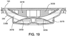
- FIG. 8 shows a perspective, cross-sectional view of the dome-shaped member 161A.
- the other dome-shaped member 161B is identical to the illustrated dome-shaped member 161A and thus, for simplicity, is not shown here.
- the dome-shaped member 161A includes a dome-shaped polypropylene portion 173A, a polypropyline bio-fine film 175A, and the magnetically attractive steel plate 162A sealed between the polypropylene portion 173A and the polypropylene film 175A.
- the polypropylene materials used for the dome-shaped portion 173A and the film 175A are biocompatible. Due to the construction of the dome-shaped member 161A, bodily fluids of a patient will only contact the biocompatible polypropylene portion 173A and the biocompatible polypropylene film 175A, and not the steel plate 162A.
- a pre-form of the dome-shaped portion 173A is first formed using an injection molding technique.
- the steel plate 162A is then positioned within a recess of the pre-form of the dome-shaped portion 173A, and the assembly of steel plate 162A and the preform are subjected to an overmolding technique in which the steel plate 162A is disposed and securely held within a mold into which molten polypropylene is injected.
- the injected molten polypropylene is allowed to solidify and form the remainder of the dome-shaped portion 173A, which partially encapsulates the steel plate 162A.
- the circumferential region of the steel plate 162A as shown in FIG.
- the polypropylene film 175A is then placed over the steel plate 162A and the dome-shaped portion 173A, and the circumferential edge region of the polypropylene film 175A is laser welded to the circumferential edge region of the dome-shaped polypropylene portion 173A. This laser weld creates a liquid-tight seal and thus seals the steel plate 162A in a liquid-tight manner between the polypropylene film 175A and the dome-shaped polypropylene portion 173A.
- any of various mechanical coupling techniques such as screwing the steel plate 162A to the dome-shaped polypropylene portion 173A and snap fitting these components together, can be used.
- a laser weld to secure the polypropylene film 175A to the dome-shaped polypropylene portion 173A
- other thermal bonding techniques that create a suitable bond can be used.
- dome-shaped portion 173A and the film 175A have been described as being formed of polypropylene, one or more other biocompatible polymers can alternatively or additionally be used.
- one or both of these components are formed of polyoxymethylene (marketed under the trade name Delrin available from Dupont of Wilmington, DE).
- Other suitable biocompatible polymers include polytetrafluoroethylene (PTFE), polyvinyl chloride, polycarbonate, and polysulfone.
- the magnetically attractive plate 162A has been described as being formed of steel, one or more other ferromagnetic materials can alternatively or additionally be used.
- Other examples of ferromagnetic materials from which the magnetically attractive plate 162A can be formed include stainless steel, iron, nickel, and cobalt.
- the thickness of the magnetically attractive plate 162A depends on the type of material from which the magnetically attractive plate 162A is formed and the desired magnetic force to be applied between the plate 162A and the actuator 133A. In some implementations, the plate 162A has a thickness of about 0.05 cm to about 0.15 cm (0.020 inch to about 0.060) inch (e.g., about 0.1 cm (0.040 inch)). In certain implementations, the magnetically attractive plate 162A is a magnet.
- the membrane 140 when compressed against the base 156, also cooperates with a series of raised ridges 167 extending from the base 156 to form a series of fluid pathways 158 and to form the multiple, depressible dome regions 146, which are widened portions (e.g., substantially circular widened portions) of the fluid pathways 158.
- the dialysis solution flows to and from the pump chambers 138A, 138B through the fluid pathways 158 and dome regions 146.
- the membrane 140 can be deflected to contact the surface of the base 156 from which the raised ridges 167 extend.
- Such contact can substantially impede (e.g., prevent) the flow of dialysis solution along the region of the pathway 158 associated with that dome region 146 during use.
- the flow of dialysis solution through the cassette 112 can be controlled through the selective depression of the depressible dome regions 146 by selectively inflating the inflatable members 142 of the PD cycler 102.
- the rigidity of the base 156 helps to hold the cassette 112 in place within the cassette compartment 114 of the PD cycler 102 and to prevent the base 156 from flexing and deforming in response to forces applied to the projections 154A, 154B by the dome-shaped members 161A, 161B and in response to forces applied to the planar surface of the base 156 by the inflatable members 142.
- the base 156 can be formed of any of various relatively rigid materials.
- the base 156 is formed of one or more polymers, such as polypropylene, polyvinyl chloride, polycarbonate, polysulfone, and other medical grade plastic materials.
- the base 156 is formed of one or more metals or alloys, such as stainless steel.
- the base 156 can alternatively be formed of various different combinations of the above-noted polymers and metals.
- the base 156 can be formed using any of various different techniques, including machining, molding, and casting techniques.
- fluid line connectors 160 are positioned along the bottom edge of the cassette 112.
- the fluid pathways 158 in the cassette 112 lead from the pumping chambers 138A, 138B to the various connectors 160.
- the connectors 160 are positioned asymmetrically along the width of the cassette 112. The asymmetrical positioning of the connectors 160 helps to ensure that the cassette 112 will be properly positioned in the cassette compartment 114 with the membrane 140 of the cassette 112 facing the cassette interface 110.
- the connectors 160 are configured to receive fittings on the ends of the dialysis solution bag lines 126, the heater bag line 128, the patient line 130, and the drain line 132.
- One end of the fitting can be inserted into and bonded to its respective line and the other end can be inserted into and bonded to its associated connector 160.
- the connectors 160 allow dialysis solution to flow into and out of the cassette 112 during use.
- the membrane 140 is attached to the periphery of the base 156.
- the portion of the membrane 140 overlying the central portion of the base 156 is typically not attached to the base 156. Rather, this portion of the membrane 140 sits loosely atop the raised ridges 165A, 165B, and 167 extending from the planar surface of the base 156.
- Any of various attachment techniques such as adhesive bonding and thermal bonding, can be used to attach the membrane 140 to the periphery of the base 156.
- the thickness and material(s) of the membrane 140 are selected so that the membrane 140 has sufficient flexibility to flex toward the base 156 in response to the force applied to the membrane 140 by the actuators 133A, 133B and the inflatable members 142.
- the membrane 140 is about 0.100 micron to about 0.150 micron in thickness. However, other thicknesses may be sufficient depending on the type of material used to form the membrane 140.
- the membrane 140 includes a three-layer laminate.
- inner and outer layers of the laminate are formed of a compound that is made up of 60 percent Septon ® 8004 thermoplastic rubber (i.e., hydrogenated styrenic block copolymer) and 40 percent ethylene
- a middle layer is formed of a compound that is made up of 25 percent Tuftec ® H1062(SEBS: hydrogenated styrenic thermoplastic elastomer), 40 percent Engage ® 8003 polyolefin elastomer (ethylene octene copolymer), and 35 percent Septon ® 8004 thermoplastic rubber (i.e., hydrogenated styrenic block copolymer).
- SEBS hydrogenated styrenic thermoplastic elastomer
- Engage ® 8003 polyolefin elastomer ethylene octene copolymer
- 35 percent Septon ® 8004 thermoplastic rubber i.e., hydrogenated styrenic block copolymer.
- the membrane can alternatively include more or
- the rigid base 156, the membrane 140, and the dome-shaped members 161A, 161B are typically formed separately and then assembled to make the cassette 112.
- the dome-shaped members 161A, 161B are attached (e.g., welded) to the membrane 140 and then inserted into the recesses 163A, 163B formed by the hollow protrusions 154A, 154B of the rigid base 156.
- the membrane 140 is then attached to the perimeter of the rigid base 156.
- a rigid cover 177 is snapped onto the cassette 112 to hold the dome-shaped members 161A, 161B in place within the pump chambers 138A, 138B.
- the cover 177 is a rigid polymeric member that has resilient tabs 179 that fit around side edge regions of the cassette 112 to firmly hold the cover against the cassette 112.
- the cover 177 includes projections 181 A, 181B that extend from a relatively planar section 183 of the cover 177 and are sized and shaped to fit within the recessed regions 163A, 163B of the base 156 of the cassette 112.
- the projections 181A, 181B extend a sufficient distance from the planar section 183 of the cover 177 to press the dome-shaped members 161A, 161B of the cassette 112 against the base 156 of the cassette 112 when the cover is snapped onto the cassette 112.
- the dome-shaped members 161A, 161B are prevented from moving around within the pump chambers 138A, 138B and potentially becoming damaged.
- the door 108 of the PD cycler 102 is opened to expose the cassette interface 110, and the cassette 112 is positioned with its membrane 140 adjacent to the cassette interface 110.
- the cassette 112 is positioned such that the pump chambers 138A, 138B of the cassette 112 are aligned with the actuators 133A, 133B.
- the cassette 112 is positioned between the locating pins 148 and the lower ledge 150 extending from the cassette interface 110.
- the asymmetrically positioned connectors 160 of the cassette act as keying features to reduce the likelihood that the cassette 112 will be installed with the membrane 140 facing in the wrong direction (e.g., facing outward toward the door 108). Additionally or alternatively, the locating pins 148 can be dimensioned to be less than the maximum protrusion of the projections 154A, 154B such that the cassette 112 cannot contact the locating pins 148 if the membrane 140 is facing outward toward the door 108.
- the actuators 133A, 133B While loading the cassette 112 into the PD cycler 102, the actuators 133A, 133B are typically retracted completely into the actuator access ports 136A, 136B. This positioning of the actuators 133A, 133B can reduce the likelihood of damage to the actuators 133A, 133B during installation of the cassette 112. In addition, retracting the actuators 133A, 133B into the access ports 136A, 136B helps to prevent the actuators 133A, 133B from being prematurely coupled to the dome-shaped members 161A, 161B in the pump chambers 138A, 138B of the cassette 112 during insertion of the cassette 112 into the cassette enclosure 114.
- FIGS. 11A-11C illustrate the pump chamber 138A and its associated dome-shaped member 161A and actuator 133A throughout different phases of operation.
- the other dome-shaped member 161B and actuator 133B operate in a similar manner to pump dialysis solution to and from the other pump chamber 138B and thus, for simplicity, the operation of those components will not be separately described.
- FIG. 11A With the cassette 112 positioned adjacent to the cassette interface 110, the door 108 is closed over the cassette 112 such that the cassette 112 is contained within the cassette compartment 114 between the door 108 and the cassette interface 110. An inflatable pad within the door 108 is then inflated to compress the cassette 112 between the door 108 and the cassette interface 110.
- This compression of the cassette 112 holds the projections 154A, 154B of the cassette 112 in the recesses 152A, 152B of the door 108 and presses the membrane 140 tightly against the raised ridges 165A, 165B, 167 extending from the planar surface of the rigid base 156 to form the enclosed fluid pathways 158, dome regions 146, and pump chambers 138A, 138B (shown in FIGS. 5 and 6 ).
- the actuator 133A is advanced toward the cassette 112 such that the magnetic actuator 133A becomes coupled to the magnetically attractive dome-shaped member 161A in the pump chamber 138A. Because the dome-shaped member 161A is attached to the membrane 140 in a manner such that the dome-shaped member 161A is centered within the pump chamber and because the cassette 112 is maintained in a desired position relative to the cassette interface 110 of the PD cycler 102, the actuator 133A is properly aligned with the dome-shaped member 161 A as the actuator 133A is advanced.
- the actuator 133A and the dome-shaped member 161A become properly coupled by simply advancing the actuator 133A.
- the actuator is further advanced to deform the membrane 140 and force the dome-shaped member 161A toward the rigid base 156 of the cassette 112.
- the volume of the pump chamber 138A decreases, causing dialysis solution to be expelled from the pump chamber 138A via the fluid pathways 158 of the cassette 112 (shown in FIGS. 5-7 ).
- the actuator 133A After expelling the dialysis solution from the pump chamber 138A, the actuator 133A is again retracted, as shown in FIG. 11C .
- the magnetic coupling of the dome-shaped member 161A causes the dome-shaped member 161A to move the membrane 140 in the same direction as the retracting actuator 133A, thereby increasing the volume of the pump chamber 138A and generating vacuum pressure of about 150 mbar to about 200 mbar within the pump chamber 138A.
- dialysis solution is drawn into the pump chamber 138A of the cassette 112 via the fluid pathways 158 of the cassette 112 (shown in FIGS. 5-7 ).
- the dialysis solution can then be forced out of the pump chamber 138A by again returning the actuator 133A to the position shown in FIG. 11B , causing the membrane 140 and the dome-shaped member 161A to move toward the rigid base 156 and thus decreasing the volume of the pump chambers 138A, 138B.
- the actuators 133A, 133B are reciprocated to sequentially alter the volume of each of the pump chambers 138A, 138B.
- the other actuator head 134B is retracted, and vice versa.
- dialysis solution is expelled from the pump chamber 138A at the same time that dialysis solution is drawn into the pump chamber 138B, and vice versa.
- certain inflatable members 142 of the PD cycler 102 can be selectively inflated to direct the pumped dialysis solution along desired pathways in the cassette 112.
- the patient line 130 is connected to a patient's abdomen via a catheter, and the drain line 132 is connected to a drain or drain receptacle.
- the PD treatment typically begins by emptying the patient of spent dialysis solution that remains in the patient's abdomen from the previous treatment.
- the pump of the PD cycler 102 is activated to cause the actuators 133A, 133B to reciprocate and selected inflatable members 142 are inflated to cause the spent dialysis solution to be drawn into the pump chambers 138A, 138B of the cassette 112 from the patient and then pumped from the pump chambers 138A, 138B to the drain via the drain line 132.
- heated dialysis solution is transferred from the heater bag 124 to the patient.
- the pump of the PD cycler 102 is activated to cause the actuators 133A, 133B to reciprocate and certain inflatable members 142 of the PD cycler 102 are inflated to cause the spent dialysis solution to be drawn into the pump chambers 138A, 138B of the cassette 112 from the heater bag 124 via the heater bag line 128 and then pumped from the pump chambers 138A, 138B to the patient via the patient line 130.
- the dialysis solution is allowed to dwell within the patient for a period of time. During this dwell period, toxins cross the peritoneum into the dialysis solution from the patient's blood. As the dialysis solution dwells within the patient, the PD cycler 102 prepares fresh dialysate for delivery to the patient in a subsequent cycle. In particular, the PD cycler 102 pumps fresh dialysis solution from one of the four full dialysis solution bags 122 into the heater bag 124 for heating.
- the pump of the PD cycler 102 is activated to cause the actuators 133A, 133B to reciprocate and certain inflatable members 142 of the PD cycler 102 are inflated to cause the dialysis solution to be drawn into the pump chambers 138A, 138B of the cassette 112 from the selected dialysis solution bag 122 via its associated line 126 and then pumped from the pump chambers 138A, 138B to the heater bag 124 via the heater bag line 128.
- the spent dialysis solution is pumped from the patient to the drain.
- the heated dialysis solution is then pumped from the heater bag 124 to the patient where it dwells for a desired period of time.
- These steps are repeated with the dialysis solution from two of the three remaining dialysis solution bags 122.
- the dialysis solution from the last dialysis solution bag 122 is typically delivered to the patient and left in the patient until the subsequent PD treatment.
- dialysis solution has been described as being pumped into the heater bag 124 from a single dialysis solution bag 122, dialysis solution can alternatively be pumped into the heater bag 124 from multiple dialysis solution bags 122. Such a technique may be advantageous, for example, where the dialysis solutions in the bags 122 have different concentrations and a desired concentration for treatment is intermediate to the concentrations of the dialysis solution in two or more of the bags 122.
- the actuators 133A, 133B are retracted away from the cassette 112 to a sufficient distance to decouple the actuators 133A, 133B and the dome-shaped members 161A, 161B of the cassette 112. As the actuators 133A, 133B are retracted away from the cassette 112, the dome-shaped members 161A, 161B retract along with the actuators 133A, 133B and cause the membrane 140 to stretch.
- the resistance applied to the dome-shaped members 161A, 161B increases until eventually the resistive force applied to the dome-shaped members 161A, 161B by the membrane exceeds the attractive force between the actuators 133A, 133B and the dome-shaped members 161A, 161B, which causes the actuators 133A, 133B to become decoupled from the dome-shaped members 161A, 161B.
- the door 108 of the PD cycler 102 is then opened and the cassette 112 is removed from the cassette compartment 114 and discarded.
- the PD system 100 does not require a vacuum system to move the portions of the membrane 140 overlying the pump chambers 138A, 138B, a substantially airtight seal between the door 108 and the cassette interface 110 is typically not required.
- the door sealing mechanism of the PD cycler 102 can be simpler and more cost effective.
- FIGS. 13-16 While the magnets 135 of the actuators 133A, 133B have been described as being arranged in the roughly concentric circular pattern shown in FIG. 12 , other magnet arrangements are possible. Examples of other magnet arrangements are illustrated in FIGS. 13-16 . In each of FIGS. 13-16 , the recesses 139A of the magnet plate 137A in which magnets 135 are disposed are shaded, and the recesses 139A that do not contain magnets are unshaded. As shown, in each of the illustrated magnet configurations, the positive poles of some of the magnets face outward and the positive poles of other magnets face inward. It has been found that this type of arrangement helps to reduce the magnetic field to which users of the PD cycler 102 are likely to be exposed.
- these magnet arrangements can result in a magnetic field of no more than about 10 Gauss (e.g., no more than about 5 Gauss) at a distance of about 3.8 cm (1.5 inches) from the actuator 133A, 133B while providing a magnetic force of at least about 44 N (10 lbf) (e.g., at least about 66 N (15 lbf)) with the dome-shaped member 161A coupled thereto.
- 10 Gauss e.g., no more than about 5 Gauss
- a magnetic force of at least about 44 N (10 lbf) e.g., at least about 66 N (15 lbf)
- the actuators 133A, 133B can be easily disassembled and re-assembled.
- the magnet arrangements can be changed between uses to ensure that an optimal magnetic force is achieved between the actuators 133A, 133B and the dome-shaped members 161A, 161B.
- dome-shaped member 161A has been described as including the film 175A bonded around the perimeter of the dome-shaped portion 173A to seal the magnetically attractive plate 162A between the film 175A and the dome-shaped portion 173A
- the cassette membrane 140 itself is bonded to the perimeter region of the dome-shaped portion 173A in order to seal the magnetically attractive plate 162A between the membrane 140 and the dome-shaped portion 173A.
- dome-shaped member 161A has been described as including the film 175A bonded around the perimeter of the dome-shaped portion 173A to seal the magnetically attractive plate 162A between the film 175A and the dome-shaped portion 173A
- a thicker and more rigid polymeric member can be used in place of the film 175A.
- a dome-shaped member 661A includes the magnetically attractive plate 162A sealed between a dome-shaped polypropylene portion 673A and a polypropylene cap 675A.
- the polypropylene cap 675A is thicker and more rigid than the film 175A and is, in many situations, more resistant than the film 175A to tearing or other damage that may jeopardize the biocompatible seal formed around the magnetically attractive plate 162A. Due to the thickness of the polypropylene cap 675A, it is typically impractical to use laser welds or certain other thermal bonds to secure the polypropylene cap 675A to the dome-shaped polypropylene portion 673A. Instead, barbs 676A extend from the polypropylene cap 675A and into mating recesses 674A in the dome-shaped polypropylene portion 673A to mechanically secure the polypropylene cap 675A to the dome-shaped polypropylene portion 673A.
- the dome-shaped polypropylene member 673A is first injection molded.
- the magnetically attractive plate 162A is then disposed in a cavity formed in the dome-shaped polypropylene member 673A, and the assembly of the magnetically attractive plate 162A and the dome-shaped polypropylene member 673A is then inserted into a mold into which molten polypropylene is injected to overmold the polypropylene cap 675A.
- the injected molten polypropylene flows into the recesses 674A in the dome-shaped polypropylene portion 673A.
- the barbs 676A are formed.
- the barbs 676A mechanically connect the polypropylene cap 675A to the dome-shaped polypropylene portion 673A.
- the polypropylene of the cap 675A bonds with the polypropylene of the dome-shaped portion 673A to further secure the polypropylene cap 675A to the dome-shaped polypropylene portion 673A.
- the mold into which the molten polypropylene is injected to form the polypropylene cap 675A is configured to include a gap between the outer perimeter of the dome-shaped polypropylene portion 673A and the inner surface of the mold.
- the molten polypropylene which will eventually solidify and form the cap, is allowed to flow around the outer perimeter of the dome-shaped portion 673A and solidify to form a wall that wraps around the circumferential edge of the dome-shaped polypropylene portion 673A and secures the cap to the dome-shaped portion 673A.
- caps and the dome-shaped portions have been described as being formed of polypropylene, it should be understood that these components can be formed of any of the various biocompatible polymeric materials discussed above with respect to the dome-shaped portion 173A and the film 175A.
- the dome-shaped member is formed using an insert injection molding technique.
- a two-part mold is opened and a steel plate is positioned between the two mold parts.
- the mold parts are then brought together to form a dome-shaped cavity in which the steel plate is positioned.
- molten biocompatible resin is injected into the cavity so that the steel plate becomes encapsulated within the molten resin.
- the mold parts are again pulled apart and the dome-shaped member is removed.
- dome-shaped members 161A, 661A can be used to form the dome-shaped members 161A, 661A.
- the polymeric portions 173A, 175A, 673A, 675A and the magnetic plate 162A are all separately made and then attached (e.g., thermally or adhesively bonded or mechanically assembled) to one another to form the dome-shaped members 161A, 661A.
- the magnetically attractive plate is coated with a biocompatible material, such as polytetrafluoroehtylene (PTFE), and the coated plate itself forms the rear surface of the dome-shaped members.
- a dome-shaped member 761A includes a PTFE-coated steel plate 762A that is secured to dome-shaped portion 773A.
- the PTFE-coated steel plate 762A simply includes the steel plate 162A described above with a PTFE coating 764A that encapsulates the plate 162A.
- the steel plate 162A is first coated with PTFE to form the coated plate 762A.
- a pre-form of the dome-shaped portion 773A is then injection molded.
- the coated plate 762A is then placed within a recessed region of the pre-form of the dome-shaped portion 773A, and the assembly of the coated plate 762A and the pre-form are disposed in a mold into which molten polypropylene is injected.
- the molten polypropylene covers the circumferential region of the coated plate 762A and solidifies to encapsulate the circumferential region of the coated plate 762A within polypropylene and thereby form the remainder of the dome-shaped polypropylene portion 773A.
- a central portion of the rear surface of the coated plate 762A remains exposed.
- the coating of the coated plate 762A has been described as being formed of PTFE, other types of coatings can alternatively or additionally be used. In certain implementations, for example, the coating is formed of gold or Parylene. Similarly, while the plate has been described as being formed of steel and the dome-shaped portion 763A has been described as being formed polypropylene, those components can alternatively be formed of any of the various other materials described above with respect to the corresponding components in the dome-shaped members 161A and 661A.
- FIG. 17 illustrates an exploded perspective view of an alternative dome-shaped member 261, which includes a biocompatible, magnetically attractive plate 262 secured to a dome-shaped biocompatible, polymeric member 273.
- the plate 262 includes a threaded bore 264 that can matingly engage threads of a threaded stem 274 extending from the dome-shaped polymeric member 273 to secure the plate 262 and the dome-shaped member 273 together. Because the plate 262 is not encapsulated, it may be exposed to fluid within the pump chamber of the cassette that is to be delivered to a patient. Thus, the plate 262 is formed of a biocompatible material.
- the plate 262 is formed of stainless steel, such as stainless steel 417, stainless steel 410, or stainless steel 17-4.
- stainless steel other types of magnetically attractive, biocompatible materials can be used to form the plate 262 of the dome-shaped member 261.
- the plate 262 can, for example, include a steel plate or magnet that is coated with a biocompatible material, such as PTFE, gold, or Parylene.
- a biocompatible coating can be applied over a non-biocompatible magnetically attractive material, such as steel.
- dome-shaped member 273 has been described as being formed of a biocompatible polymeric material, biocompatible materials of other types, such as biocompatible metals, can alternatively or additionally be used.
- both the magnetic plate 262 and the dome-shaped member 273 are formed of stainless steel.
- pump chambers 138A, 138B have been described as being sized to pump about 12-13 ml of fluid with each actuator stroke, the pump chambers 138A, 138B and the dome-shaped members 161A, 161B disposed in those chambers can be sized to pump different volumes of fluid. In certain implementations, for example, the pump chambers 138A, 138B are sized to pump about 25-30 ml of fluid per actuator stroke.
- the cassette includes members that are not attached to the cassette membrane 140.
- the dome-shaped members are provided with magnets that are attracted to the magnets of the actuators. As a result of the strong attraction between these magnets, the magnets can help to properly align the dome-shaped members within the pump chambers.
- a PD cassette 312 includes a magnetically attractive member 361B that is mechanically restrained within a pump chamber 338B formed between a rigid base 356 and the membrane 140 to maintain proper alignment of the member 361B within the pump chamber 338B.
- Amagnetically attractive member 361A that is identical to the member 361B is typically positioned in an additional pump chamber 338A formed between the rigid base 356 and the membrane 140.
- the member 361A is not shown in the pump chamber 338A in FIG. 18 in order to provide a clearer view of the portion of the rigid base 356 that forms the pump chamber 338A, which is similar to the portion of the rigid base 356 that forms the pump chamber 338B. As shown in FIGS.
- the magnetically attractive member 361B includes a dome-shaped portion 363B that is similar in construction to the dome-shaped member 161A described above.
- Four resilient legs 365B extend from the dome-shaped portion 363B and sit within slots 367B formed by the base 356.
- the top surface of the member 361B is in contact with or in near contact with the membrane 140 when the member 361B is in an uncompressed state. As a result, the resilient legs 365B are retained in the slots 367B of the base 356.
- the cassette 312 can be used in the PD cycler 102 in generally the same way as the cassettes described above.
- the resilient legs 367B of the member 361B collapse and allow the hemispherical portion 363B of the member 361B to come into contact with or into near contact with the base 356.
- the resilient legs 367B can, for example, collapse upon being subjected to a compression force of about two pounds or greater (e.g., about five pounds or greater).
- the volume of the pump chamber 338B decreases as a result of this movement, causing fluid to be expelled from the pump chamber 338B.
- the actuator 133B is subsequently retracted, and the magnetic coupling between the actuator 133B and the magnetically attractive plate within the hemispherical portion 363B of the member 361 causes the member 361B to be retracted along with the actuator 133B.
- the volume of the pump chamber 338B increases as a result of this movement, causing fluid to be drawn into the pump chamber 338B.
- FIGS. 20A and 20B show the operation of a PD cycler 402 that includes decoupling posts 410 and an actuator 433A that has bores 412 that extend through a magnet plate 437A and cap plate 441A of the actuator 433A.
- the bores 412 are sized and arranged to receive the decoupling posts 410 of the PD cycler 402.
- the PD cycler 402 is substantially the same as the PD cycler 102 described above. As with the PD cycler 102 described above, the PD cycler 402 also includes a second actuator that is similar to the actuator 433A.
- the cassette 112 is disposed within a cassette enclosure 414 of the PD cycler 402 such that the actuators of the PD cycler 402 align with the pump chambers 138A, 138B of the cassette. For simplicity, only the operation of the actuator 433A associated with the pump chamber 138A is shown and described with respect to FIGS. 20A and 20B .
- the PD cycler 402 is generally operated in the same manner as the PD cycler 102 described above. As shown in FIG. 20A , as the actuator 433A is advanced to expel fluid from the pump chamber 138A, the membrane 140 of the cassette 112 is not in contact with the decoupling posts 410. Rather, the decoupling posts 410 terminate at points within the bores 412 of the actuator 433A. As the actuator 433A is reciprocated during use to draw fluid into and pump fluid out of the pump chamber 138A, the decoupling posts 410 remain out of contact with the membrane 140. Thus, fluid can be expelled from and drawn into the pump chamber 138A without interference from the decoupling posts 410.
- the actuator 433A Upon completion of the treatment, the actuator 433A is retracted into the actuator access port 136A.
- the decoupling posts 410 are held in a fixed position. As a result, as the actuator 433A, the membrane 140, and the dome-shaped member 161A are together retracted, the ends of the decoupling posts 410 contact the membrane 140 and resist further axial movement of the membrane 140 and the dome-shaped member 161A. Due to the bores 412 formed in the actuator 433A, the actuator 433A is able to be drawn proximal to the ends of the decoupling posts 410. Continued retraction of the actuator 433A causes the dome-shaped member 161A to become decoupled from the magnets 135 of the actuator 433A, as shown in FIG. 21B .
- the decoupling posts 410 advantageously allow the actuator 433A and the dome-shaped member 161A to be decoupled from one another without excessively stretching the membrane 140 of the cassette 112.
- magnetically attractive members and the pump chambers of the above-described cassettes have been described as being dome-shaped, magnetically attractive members and pump chambers of other mating shapes can be used.
- the magnetically attractive members and pump chambers can be cylindrical, rectangular, etc.
- the magnetically attractive members that are disposed within the cassette pump chambers have been described as including one or more biocompatible polymers, they can alternatively be formed of other types of biocompatible materials, such as biocompatible metals.
- the dome-shaped members are formed entirely of stainless steel.
- the actuators of the PD cyclers described above include permanent magnets, other types of magnetic devices can be used.
- the actuators are equipped with electromagnetic devices.
- the magnetic coupling between the actuators and the members disposed within the pump chambers of the cassette can be broken by simply turning off the current to the electromagnetic device.
- the magnets 135 have been described as being contained in the actuators of the PD cycler and the members disposed within the pump chambers of the cassettes have been described as including magnetically attractive materials that can be attracted to the magnets in the actuators, in some implementations, the members disposed within the pump chambers contain the magnets and the actuators include the magnetically attractive materials that can be attracted to the magnets. In still other implementations, both the member disposed within the pump chambers and the actuators of the PD cycler contain magnets.
- a dialysis system includes a dialysis machine having magnetic actuators that are magnetically coupled directly to a magnetically attractive membrane that partially forms the pump chambers of the cassette.
- a PD system 500 includes a PD cycler 502 having pistons (also referred to as actuators) 533A, 533B that include electromagnetic, dome-shaped piston heads 534A, 534B attached (e.g., engaged by mating threads, thermally bonded, adhesively bonded, snap fit, etc.) to piston shafts 543A, 543B.
- Each of the piston heads 534A, 534B includes a cavity in which an electromagnet is contained.
- Each of the piston heads 534A, 534B can, for example, include a rear end cap that can be secured to the front dome-shaped portion of the piston head to form the cavity in which the electromagnet is contained.
- the electromagnet can be threadedly engaged with or otherwise attached to the front dome-shaped member of the piston head.
- a power source e.g., a battery or a mains power supply to which the PD cycler 502 is connected
- a power source can be connected to the electromagnets in the piston heads 534A, 534B via lead lines such that current can be transmitted to the electromagnets.
- the magnetic field surrounding the piston heads 534A, 534B is very weak such that little or no attraction is experienced between the piston heads 534A, 534B and magnetically attractive objects in close proximity to the piston heads 534A, 534B.
- a current flowing in a first direction through the electromagnet creates a magnetic field causing magnets in close proximity to the piston heads 534A, 534B to be attracted to the piston heads 534A, 534B, and a current flowing in a second, opposite direction through the piston heads 534A, 534B creates a magnetic field causing magnets (of the same polarity as the magnets mentioned above) in close proximity to the piston heads 534A, 534B to be repelled away from the piston heads 534A, 534B.
- the piston heads 534A, 534B are typically formed of stainless steel. However, other metals, such as aluminum, and certain polymeric materials can alternatively or additionally be used to the form the piston heads 534A, 534B.
- electromagnet An example of a suitable electromagnet is the EM050-12-222 electromagnet, available from APW Company (Rockaway, NJ). However, other types of electromagnets can alternatively or additionally be used.
- Each of the pistons 533A, 533B is connected to a motor (e.g., a stepper motor) positioned in the housing 106 of the PD cycler 502 so that the pistons 533A, 533B can be axially moved within the access ports 136A, 136B formed in the cassette interface 110 of the PD cycler 502.
- a motor e.g., a stepper motor
- the PD cycler 502 has generally the same structure as and operates in a similar manner to the PD cycler 102 described above.
- the PD system illustrated in Fig. 21 also includes a PD cassette 512 that includes a magnetically attractive membrane 540 (shown in Figs. 22A-22C ) attached to the base 156 of the cassette 512. Similar to the membrane 140 described above, the magnetically attractive membrane 540 covers substantially the entire base 156 and is attached (e.g., thermally or adhesively bonded) only to the periphery of the base 156.
- the magnetically attractive membrane 540 is typically formed of the same materials as the membrane 140 but also includes an outer layer of magnetically attractive material.
- the outer layer can, for example, be a layer of magnetically attractive paint. The outer layer is typically restricted only to those portions of the membrane overlying the fluid pump chambers 538A, 538B.
- the outer layer of magnetically attractive material can alternatively be applied to the entire surface of the membrane.
- a suitable magnetically attractive paint is RUST-OLEUM ® Specialty magnetic latex primer, available from RUST-OLEUM ® Corporation (Vernon Hills, IL).
- the PD cassette 512 does not include magnetically attractive dome-shaped members inside its pump chambers 538A, 538B. Instead, the pump chambers 538A, 538B are vacant, except for containing liquid during use. As described in greater detail below, when the electromagnetic piston heads 534A, 534B are magnetically activated, they can be coupled directly to the magnetically attractive membrane 540 of the cassette 512 such that the magnetically attractive membrane 540 can be reciprocated along with the piston heads 534A, 534B.
- the cassette 512 is loaded into the cassette compartment 114 of the PD cycler 502 in much the same way that the cassette 112 was previously described as being loaded into the cassette compartment 114 of the PD cycler 102. While loading the cassette 512 into the PD cycler 502, current does not flow through the electromagnets 535A, 535B of the pistons 533A, 533B such that little or no magnetic attraction is experienced between the magnetic piston heads 534A, 534B and the magnetically attractive membrane 540 of the cassette 512. In addition, the pistons 533A, 533B are typically retracted completely into the access ports 136A, 136B to reduce the likelihood of damage to the membrane 540 during installation of the cassette 512.
- Retracting the pistons 533A, 533B into the access ports 136A, 136B can also help to prevent the piston heads 534A, 534B from being prematurely coupled to the magnetically attractive membrane 540 during installation, which could result in the piston heads 534A, 534B being misaligned with respect to the pump chambers 538A, 538B and could lead to inaccurate fluid pumping.
- FIGS. 22A-22C illustrate the portion of the cassette 512 including the pump chamber 538A and its associated piston 533A throughout different phases of operation.
- the other piston 533B and pump chamber 538B cooperate in a similar manner to pump dialysis solution to and from the other pump chamber 538B and thus, for simplicity, the operation of those components will not be separately described.
- the door 108 of the PD cycler 502 is closed over the cassette 512 such that the cassette 512 is contained within the cassette compartment 114 between the door 108 and the cassette interface 110.
- An inflatable pad within the door 108 is then inflated to compress the cassette 512 between the door 108 and the cassette interface 110.
- This compression of the cassette 512 holds the projections 154A, 154B of the cassette 512 in the recesses 152A, 152B of the door 108 and presses the membrane 540 tightly against the raised ridges extending from the planar surface of the rigid base 156 to form the various fluid pathways and chambers of the cassette 512.
- a current is applied to the piston head 534A to magnetically activate the piston head 534A, and the piston 533A is advanced toward the cassette 512 such that the piston head 534A becomes coupled to the portion of the magnetically attractive membrane 540 overlying the pump chamber 538A of the cassette 512.
- the piston 533A is then further advanced to deform the membrane 540 toward the rigid base 156 of the cassette 512, causing dialysis solution to be expelled from the pump chamber 538A via the fluid pathways of the cassette 512.
- the piston 533A is again retracted, as shown in FIG. 22C . Due to the magnetic coupling between the piston head 534A and the membrane 540, the membrane 540 is retracted along with the piston 533A, thereby increasing the volume of the pump chamber 538A and generating vacuum pressure of about 150 mbar to about 200 mbar within the pump chamber 538A. As a result, dialysis solution is drawn into the pump chamber 538A via the fluid pathways of the cassette 512.
- This technique can be used to carry out a PD treatment in much the same way as described above with respect to the PD system 100.
- the current applied to the electromagnets 535A, 535B in the piston heads 534A, 534B is reverse, causing a repelling force between the piston heads 534A, 534B and the membrane 540. This allows the user to easily remove the cassette 512 from the cassette compartment 114 with reduced risk of tearing the membrane 540.
- piston heads 534A, 534B have been described as including electromagnets, permanently magnetic piston heads can alternatively or additionally be used. In such cases, permanent magnets, rather than electromagnets, can be contained in the cavities of the piston heads. In order to release the coupling between the permanently magnetic piston heads and the magnetically attractive membrane after treatment, the piston heads would be retracted a sufficient distance to overcome the magnetic coupling force.
- each of the piston heads 534A, 534B has been described as including a single magnet (electromagnet or permanent magnet), it should be understood that multiple magnets can be contained within the piston heads 534A, 534B to achieve a desired magnetic force.
- the membrane 540 has been described as including an outer layer of magnetically attractive material, such as paint or primer, in certain implementations, the magnetically attractive material is incorporated into the body of the membrane.
- the magnetically attractive material is incorporated into the body of the membrane.
- iron particles can be suspended within the body of the membrane.
- membranes 140, 540 have been described as being attached only to the periphery of the base 156 of the cassettes 112, 512, in certain implementations the membranes 140, 540 are also attached (e.g., thermally or adhesively bonded) to the raised features 165A, 165B, 167 extending from the planar surface of the base 156.
- membranes 140, 540 have been described as covering substantially the entire surface of the base 156 of the cassettes 112, 512, membranes covering only the pump chambers can alternatively be used.
- the fluid pathways extending from the pump chambers of the cassette can be provided by tubing that is fluidly connected to the pump chambers.
- cassettes discussed above have been described as having two pump chambers, the cassettes can alternatively have more or fewer than two pump chambers.
- each of the pump chambers of the cassettes described above has been described as including a fluid inlet port and a fluid outlet port, the pump chambers can alternatively include a single port that is used as both an inlet and an outlet.
- cassettes have been described as being positioned between locating pins and a lower ledge extending from a cassette interface of the PD cycler in order to hold the cassette in a position such that the actuator heads align with the pump chambers of the cassette
- other techniques for ensuring that the actuator heads align with the pump chambers can alternatively or additionally be used.
- the cassette is placed against the door of the PD cycler with the hollow projections of the cassette disposed in recesses of the PD cycler's door. The cassette is held in this position by retainer clips attached to the door. Upon closing the door, the actuator heads of the PD cycler align with the pump chambers of the cassette.
- the PD cycler can include other types of screens and user data entry systems.
- the cycler includes a display screen with buttons (e.g., feathertouch buttons) arranged on the console adjacent the display screen.
- buttons e.g., feathertouch buttons
- Certain buttons can be arranged to be aligned with operational options displayed on the screen during use such that the user can select a desired operational option by pressing the button aligned with that operational option.
- Additional buttons in the form of arrow buttons can also be provided to allow the user to navigate through the various display screens and/or the various items displayed on a particular screen.
- Other buttons can be in the form of a numerical keypad to allow the user to input numerical values in order, for example, to input operational parameters.
- a select or enter button can also be provided to allow the user to select an operational option to which the user navigated by using the arrow keys and/or to allow the user to enter values that the user inputted using the numerical keypad.
- doors of the PD cyclers described above are shown as being positioned on a front face of the PD cyclers, the doors can alternatively be positioned at various other locations on the PD cyclers.
- the doors could be positioned on a top face of the PD cycler such that the cassette is slid into the cassette compartment in a substantially horizontal orientation instead of a substantially vertical orientation.
- the PD cyclers discussed above include inflatable pads in their doors to compress the cassette between the door and the cassette interface
- the PD cyclers can alternatively or additionally include inflatable pads positioned behind the cassette interface.
- other mechanisms suitable for compressing the cassette can be used.
- cassettes described above have been described as being part of a PD system, these types of cassettes can be used in any of various other types of cassette-based medical fluid pumping systems.
- Other examples of medical fluid pumping systems with which cassettes described herein can be used include hemodialysis systems, blood perfusion systems, and intravenous infusion systems.
- cassettes have been described as being used to pump dialysis solution
- other types of dialysis fluids can be pumped through the cassettes.
- blood can be pumped through the cassettes.
- priming solutions such as saline
- any of various other types of medical fluids can be pumped through the above-described cassettes depending on the type of medical fluid pumping machines with which the cassettes are used.
Landscapes
- Health & Medical Sciences (AREA)
- Heart & Thoracic Surgery (AREA)
- Urology & Nephrology (AREA)
- Emergency Medicine (AREA)
- Engineering & Computer Science (AREA)
- Hematology (AREA)
- Anesthesiology (AREA)
- Biomedical Technology (AREA)
- Vascular Medicine (AREA)
- Life Sciences & Earth Sciences (AREA)
- Animal Behavior & Ethology (AREA)
- General Health & Medical Sciences (AREA)
- Public Health (AREA)
- Veterinary Medicine (AREA)
- Mechanical Engineering (AREA)
- General Engineering & Computer Science (AREA)
- External Artificial Organs (AREA)
- Infusion, Injection, And Reservoir Apparatuses (AREA)
Claims (10)
- Système de pompage de fluide médical, comprenant :une machine de pompage de fluide médical (402) définissant un coffret à cassette (114), la machine de pompage de fluide médical (402) comprenant un dispositif d'actionnement (433A) ; etune cassette de fluide médical (112) configurée pour être disposée à l'intérieur du coffret à cassette (114) de la machine de pompage de fluide médical (402), la cassette de fluide médical comprenant :une base (156) ;une membrane (140) fixée à la base (156), la membrane (140) et une région de la base (156) coopérant de façon à définir une chambre de pompe à fluide (138A), la cassette (112) pouvant être positionnée à l'intérieur du coffret à cassette (114) de la machine de pompage de fluide médical de telle sorte que le dispositif d'actionnement (433A) soit essentiellement aligné sur la chambre de pompe à fluide (138A) ; etun organe (161A) disposé à l'intérieur de la chambre de pompe à fluide (138A), l'organe (161A) ayant une attraction magnétique à l'égard du dispositif d'actionnement (433A) de telle sorte que l'organe (161A) et le dispositif d'actionnement (433A) soient configurés pour être accouplés l'un à l'autre avec une partie de la membrane (140) positionnée entre le dispositif d'actionnement (433A) et l'organe (161A) lorsque la cassette (112) est disposée à l'intérieur du coffret à cassette (114), dans lequel le dispositif d'actionnement (433A) est configuré pour être rétracté d'une certaine distance vis-à-vis de la base (156) de la cassette (112) afin de désaccoupler le dispositif d'actionnement (433A) de l'organe (161A), dans lequel la machine de pompage de fluide médical (402) comprend une broche de désaccouplement (410) qui est conçue pour être reçue dans un orifice (412) au moins partiellement formé par le dispositif d'actionnement (433A) lorsque le dispositif d'actionnement (433A) est rétracté, et la broche de désaccouplement (410) est configurée pour empêcher un déplacement de l'organe (161A) dans une direction de rétraction du dispositif d'actionnement (433A) afin de faciliter le désaccouplement du dispositif d'actionnement (433A) vis-à-vis de l'organe (161A).
- Système de pompage de fluide médical selon la revendication 1, dans lequel l'organe (161A) est profilé de façon à épouser essentiellement un évidement dans la région de la base qui coopère avec la membrane afin de former la chambre de pompe à fluide (138A), dans lequel l'organe (161A) et l'évidement dans la région de la base qui coopère avec la membrane afin de former la chambre de pompe à fluide (138A) sont essentiellement en forme de dôme.
- Système de pompage de fluide médical selon la revendication 1, dans lequel le dispositif d'actionnement (433A) comprend un ou plusieurs aimants, et l'organe (161A) comprend un matériau magnétique qui a une attraction à l'égard des aimants, dans lequel l'organe (161A) comprend une plaque magnétique qui est assujettie à un matériau non magnétique, et dans lequel la plaque magnétique est entourée par le matériau non magnétique.
- Système de pompage de fluide médical selon la revendication 1, dans lequel le dispositif d'actionnement (433A) comprend une plaque à aimants (437A) qui définit une pluralité d'évidements et une pluralité d'aimants (135) disposés dans les évidements.
- Système de pompage de fluide médical selon la revendication 4, dans lequel les aimants sont placés dans les évidements de telle sorte qu'au moins certains aimants adjacents présentent des polarités opposées, dans lequel au moins certains des aimants sont agencés selon un motif circulaire, et tous les aimants circonférentiellement adjacents au sein du motif circulaire présentent des polarités opposées.
- Système de pompage de fluide médical selon la revendication 4, dans lequel le dispositif d'actionnement (433A) comprend en outre une plaque de couverture qui peut être assujettie à la plaque à aimants qui définit les évidements afin de retenir les aimants à l'intérieur des évidements.
- Système de pompage de fluide médical selon la revendication 1, dans lequel l'organe (161A) comporte une surface essentiellement plane qui s'accole à une surface essentiellement plane du dispositif d'actionnement, ou dans lequel l'organe (161A) est fixé à la membrane de la cassette.
- Système de pompage de fluide médical selon la revendication 1, dans lequel l'organe (161A) comprend une première partie et une pluralité de pattes élastiques s'étendant à partir de la première partie, dans lequel la base définit des canaux configurés pour recevoir les pattes afin de maintenir l'organe (161A) dans une position souhaitée à l'intérieur de la chambre (138A) ; et/ou dans lequel la première partie est essentiellement en forme de dôme.
- Système de pompage de fluide médical selon la revendication 1, dans lequel la machine de pompage de fluide médical (402) comprend un second dispositif d'actionnement (133B), et la membrane et des régions de la base (156) coopèrent afin de définir une seconde chambre de pompe à fluide (138B), la cassette pouvant être positionnée à l'intérieur du coffret à cassette de la machine de pompage de fluide médical (402) de telle sorte que les dispositifs d'actionnement (133A, 133B) s'alignent essentiellement sur les chambres de pompe à fluide (138A, 138B), et un second organe (161B) est disposés à l'intérieur de la chambre de pompe à fluide, respectivement, les organes (161A, 161B) ayant une attraction magnétique à l'égard des dispositifs d'actionnement lorsque la cassette (112) est disposée à l'intérieur du coffret à cassette (114).
- Système de pompage de fluide médical selon la revendication 1, dans lequel le dispositif d'actionnement (433A) comprend un aimant permanent et/ou un aimant électromagnétique.
Applications Claiming Priority (2)
| Application Number | Priority Date | Filing Date | Title |
|---|---|---|---|
| US201061425050P | 2010-12-20 | 2010-12-20 | |
| PCT/US2011/065415 WO2012087798A2 (fr) | 2010-12-20 | 2011-12-16 | Cassettes de fluide médical et systèmes et procédés afférents |
Publications (2)
| Publication Number | Publication Date |
|---|---|
| EP2654825A2 EP2654825A2 (fr) | 2013-10-30 |
| EP2654825B1 true EP2654825B1 (fr) | 2017-08-02 |
Family
ID=45476642
Family Applications (1)
| Application Number | Title | Priority Date | Filing Date |
|---|---|---|---|
| EP11808070.4A Active EP2654825B1 (fr) | 2010-12-20 | 2011-12-16 | Cassettes de fluide médical et systèmes et procédés afférents |
Country Status (3)
| Country | Link |
|---|---|
| US (1) | US9694125B2 (fr) |
| EP (1) | EP2654825B1 (fr) |
| WO (1) | WO2012087798A2 (fr) |
Families Citing this family (66)
| Publication number | Priority date | Publication date | Assignee | Title |
|---|---|---|---|---|
| US7744553B2 (en) | 2003-12-16 | 2010-06-29 | Baxter International Inc. | Medical fluid therapy flow control systems and methods |
| WO2006086490A1 (fr) | 2005-02-07 | 2006-08-17 | Medtronic, Inc. | Detecteur de desequilibre ionique |
| US9399091B2 (en) | 2009-09-30 | 2016-07-26 | Medtronic, Inc. | System and method to regulate ultrafiltration |
| DE112012001381T5 (de) | 2011-03-23 | 2014-01-02 | Nxstage Medical, Inc. | Peritoneal-Dialyse-Systeme, -Vorrichtungen und -Verfahren |
| US9861733B2 (en) | 2012-03-23 | 2018-01-09 | Nxstage Medical Inc. | Peritoneal dialysis systems, devices, and methods |
| US9561316B2 (en) | 2011-04-29 | 2017-02-07 | Medtronic, Inc. | Intersession monitoring for blood fluid removal therapy |
| US9456755B2 (en) | 2011-04-29 | 2016-10-04 | Medtronic, Inc. | Method and device to monitor patients with kidney disease |
| US9848778B2 (en) | 2011-04-29 | 2017-12-26 | Medtronic, Inc. | Method and device to monitor patients with kidney disease |
| ES2647775T3 (es) | 2011-08-02 | 2017-12-26 | Medtronic, Inc. | Sistema de hemodiálisis que tiene una trayectoria de flujo con un volumen distensible controlado |
| US10857277B2 (en) | 2011-08-16 | 2020-12-08 | Medtronic, Inc. | Modular hemodialysis system |
| US9713668B2 (en) | 2012-01-04 | 2017-07-25 | Medtronic, Inc. | Multi-staged filtration system for blood fluid removal |
| US10905816B2 (en) | 2012-12-10 | 2021-02-02 | Medtronic, Inc. | Sodium management system for hemodialysis |
| US9707328B2 (en) | 2013-01-09 | 2017-07-18 | Medtronic, Inc. | Sorbent cartridge to measure solute concentrations |
| US11565029B2 (en) | 2013-01-09 | 2023-01-31 | Medtronic, Inc. | Sorbent cartridge with electrodes |
| US9713666B2 (en) | 2013-01-09 | 2017-07-25 | Medtronic, Inc. | Recirculating dialysate fluid circuit for blood measurement |
| US11154648B2 (en) | 2013-01-09 | 2021-10-26 | Medtronic, Inc. | Fluid circuits for sorbent cartridge with sensors |
| US10850016B2 (en) | 2013-02-01 | 2020-12-01 | Medtronic, Inc. | Modular fluid therapy system having jumpered flow paths and systems and methods for cleaning and disinfection |
| US10010663B2 (en) | 2013-02-01 | 2018-07-03 | Medtronic, Inc. | Fluid circuit for delivery of renal replacement therapies |
| US9526822B2 (en) | 2013-02-01 | 2016-12-27 | Medtronic, Inc. | Sodium and buffer source cartridges for use in a modular controlled compliant flow path |
| US9623164B2 (en) | 2013-02-01 | 2017-04-18 | Medtronic, Inc. | Systems and methods for multifunctional volumetric fluid control |
| US10543052B2 (en) | 2013-02-01 | 2020-01-28 | Medtronic, Inc. | Portable dialysis cabinet |
| US9827361B2 (en) | 2013-02-02 | 2017-11-28 | Medtronic, Inc. | pH buffer measurement system for hemodialysis systems |
| US9144640B2 (en) | 2013-02-02 | 2015-09-29 | Medtronic, Inc. | Sorbent cartridge configurations for improved dialysate regeneration |
| US9714650B2 (en) * | 2013-06-11 | 2017-07-25 | Matthew G. Morris, Jr. | Pumping system |
| DE102013013415A1 (de) | 2013-08-09 | 2015-02-12 | Fresenius Medical Care Deutschland Gmbh | Kassettenmodul |
| WO2015066731A2 (fr) | 2013-11-04 | 2015-05-07 | Medtronic, Inc. | Procédé et dispositif pour gérer des volumes de fluides dans le corps |
| US9884145B2 (en) | 2013-11-26 | 2018-02-06 | Medtronic, Inc. | Parallel modules for in-line recharging of sorbents using alternate duty cycles |
| US10537875B2 (en) | 2013-11-26 | 2020-01-21 | Medtronic, Inc. | Precision recharging of sorbent materials using patient and session data |
| CN105992552B (zh) | 2013-11-27 | 2019-06-18 | 美敦力公司 | 精确透析监测及同步系统 |
| DE102014103506A1 (de) * | 2014-03-14 | 2015-09-17 | Fresenius Medical Care Deutschland Gmbh | Blutbehandlungskassette mit gedelltem Folienventil sowie Blutbehandlungsvorrichtung |
| WO2015147617A1 (fr) * | 2014-03-28 | 2015-10-01 | 엘지전자 주식회사 | Procédé pour une opération de dispositif à dispositif (d2d) réalisée par un terminal dans un système de communication sans fil, et terminal utilisant le procédé |
| JP2015213596A (ja) * | 2014-05-09 | 2015-12-03 | ニプロ株式会社 | 携帯型血液透析用除水ポンプ |
| USD724741S1 (en) * | 2014-06-05 | 2015-03-17 | Deka Products Limited Partnership | Enclosure skirt for a peritoneal dialysis device |
| USD725782S1 (en) | 2014-06-05 | 2015-03-31 | Deka Products Limited Partnership | Bottom panel of an enclosure |
| USD725277S1 (en) * | 2014-06-05 | 2015-03-24 | Deka Products Limited Partnership | Door for a peritoneal dialysis device |
| USD725780S1 (en) * | 2014-06-05 | 2015-03-31 | Deka Products Limited Partnership | Heater tray for a peritoneal dialysis device |
| USD724742S1 (en) | 2014-06-05 | 2015-03-17 | Deka Products Limited Partnership | Rear panel of an enclosure |
| USD725781S1 (en) * | 2014-06-05 | 2015-03-31 | Deka Products Limited Partnership | Container holder for a peritoneal dialysis device |
| USD724740S1 (en) * | 2014-06-05 | 2015-03-17 | Deka Products Limited Partnership | Enclosure for a peritoneal dialysis device |
| WO2015199766A1 (fr) | 2014-06-24 | 2015-12-30 | Medtronic, Inc. | Ensemble de régénération de dialysat modulaire |
| WO2015199768A1 (fr) | 2014-06-24 | 2015-12-30 | Medtronic, Inc. | Ensemble sorbant empilé |
| US10697447B2 (en) * | 2014-08-21 | 2020-06-30 | Fenwal, Inc. | Magnet-based systems and methods for transferring fluid |
| US10098993B2 (en) | 2014-12-10 | 2018-10-16 | Medtronic, Inc. | Sensing and storage system for fluid balance |
| US9713665B2 (en) | 2014-12-10 | 2017-07-25 | Medtronic, Inc. | Degassing system for dialysis |
| US9895479B2 (en) | 2014-12-10 | 2018-02-20 | Medtronic, Inc. | Water management system for use in dialysis |
| US10874787B2 (en) | 2014-12-10 | 2020-12-29 | Medtronic, Inc. | Degassing system for dialysis |
| WO2017078965A1 (fr) | 2015-11-06 | 2017-05-11 | Medtronic, Inc | Optimisation de prescription de dialyse pour réduire le risque d'arythmie |
| US10874790B2 (en) | 2016-08-10 | 2020-12-29 | Medtronic, Inc. | Peritoneal dialysis intracycle osmotic agent adjustment |
| US10994064B2 (en) | 2016-08-10 | 2021-05-04 | Medtronic, Inc. | Peritoneal dialysate flow path sensing |
| US11013843B2 (en) | 2016-09-09 | 2021-05-25 | Medtronic, Inc. | Peritoneal dialysis fluid testing system |
| US10441702B2 (en) * | 2016-10-04 | 2019-10-15 | Fresenius Medical Care Holdings, Inc. | Medical fluid temperature control |
| US10981148B2 (en) | 2016-11-29 | 2021-04-20 | Medtronic, Inc. | Zirconium oxide module conditioning |
| US10960381B2 (en) | 2017-06-15 | 2021-03-30 | Medtronic, Inc. | Zirconium phosphate disinfection recharging and conditioning |
| US11278654B2 (en) | 2017-12-07 | 2022-03-22 | Medtronic, Inc. | Pneumatic manifold for a dialysis system |
| US11033667B2 (en) | 2018-02-02 | 2021-06-15 | Medtronic, Inc. | Sorbent manifold for a dialysis system |
| US11110215B2 (en) | 2018-02-23 | 2021-09-07 | Medtronic, Inc. | Degasser and vent manifolds for dialysis |
| JP2021516089A (ja) | 2018-02-28 | 2021-07-01 | ネクステージ メディカル インコーポレイテッド | 流体調製および処置装置、方法、およびシステム |
| US11115073B2 (en) | 2018-04-20 | 2021-09-07 | Huawei Technologies Co., Ltd. | Method and device for decreasing electromagnetic radiation specific absorption rate |
| US11213616B2 (en) | 2018-08-24 | 2022-01-04 | Medtronic, Inc. | Recharge solution for zirconium phosphate |
| US11806457B2 (en) | 2018-11-16 | 2023-11-07 | Mozarc Medical Us Llc | Peritoneal dialysis adequacy meaurements |
| US11806456B2 (en) | 2018-12-10 | 2023-11-07 | Mozarc Medical Us Llc | Precision peritoneal dialysis therapy based on dialysis adequacy measurements |
| US11207452B2 (en) | 2019-08-30 | 2021-12-28 | Fresenius Medical Care Holdings, Inc. | Multi-lumen tube assemblies for medical fluid pumping systems |
| US11850344B2 (en) | 2021-08-11 | 2023-12-26 | Mozarc Medical Us Llc | Gas bubble sensor |
| US11965763B2 (en) | 2021-11-12 | 2024-04-23 | Mozarc Medical Us Llc | Determining fluid flow across rotary pump |
| US11944733B2 (en) | 2021-11-18 | 2024-04-02 | Mozarc Medical Us Llc | Sodium and bicarbonate control |
| US20230181809A1 (en) * | 2021-12-13 | 2023-06-15 | Medtronic Xomed, Inc. | Surgical devices, systems, and methods facilitating multiple flow path fluid management |
Family Cites Families (321)
| Publication number | Priority date | Publication date | Assignee | Title |
|---|---|---|---|---|
| US329773A (en) | 1885-11-03 | perry | ||
| US5935099A (en) | 1992-09-09 | 1999-08-10 | Sims Deltec, Inc. | Drug pump systems and methods |
| US6241704B1 (en) | 1901-11-22 | 2001-06-05 | Sims Deltec, Inc. | Drug pump systems and methods |
| US2383193A (en) | 1943-11-01 | 1945-08-21 | Oliver United Felters Inc | Diaphragm pump |
| US2886281A (en) | 1957-03-05 | 1959-05-12 | Otis Eng Co | Control valve |
| US3083943A (en) | 1959-07-06 | 1963-04-02 | Anbrey P Stewart Jr | Diaphragm-type valve |
| GB1096644A (en) | 1964-05-06 | 1967-12-29 | Applic Gomma Anti Vibranti S A | Resilient suspension system, more particularly for motor vehicles |
| DE1816596A1 (de) * | 1968-12-23 | 1970-07-02 | Kafka Dipl Ing Wilhelm | Kuenstliches Herz |
| US3556465A (en) | 1969-06-09 | 1971-01-19 | Rkl Controls | Diaphragm valve assembly and method of making same |
| US3689025A (en) | 1970-07-30 | 1972-09-05 | Elmer P Kiser | Air loaded valve |
| US4370983A (en) | 1971-01-20 | 1983-02-01 | Lichtenstein Eric Stefan | Computer-control medical care system |
| US6189857B1 (en) | 1971-04-13 | 2001-02-20 | The United States Of America As Represented By The United States Department Of Energy | Fluid-actuated rapid closure valve |
| US3927955A (en) | 1971-08-23 | 1975-12-23 | East West Medical Products Inc | Medical cassette pump |
| DE2355966A1 (de) | 1973-11-09 | 1975-05-22 | Medac Klinische Spezialpraep | Pumpenanordnung, insbesondere fuer blutpumpen |
| US3880053A (en) * | 1974-05-31 | 1975-04-29 | Tl Systems Corp | Pump |
| US3985135A (en) | 1975-03-31 | 1976-10-12 | Baxter Laboratories, Inc. | Dual chamber reservoir |
| US4026669A (en) | 1975-07-14 | 1977-05-31 | Baxter Laboratories, Inc. | Variable capacity reservoir assembly |
| GB1483702A (en) | 1976-01-14 | 1977-08-24 | Instr Constr & Maintenance Ltd | Fluid valve |
| DE2628238A1 (de) | 1976-06-24 | 1978-01-05 | Gerhard Dr Ing Kunz | Ventil zum aufrechterhalten von gegendruecken in von medien durchstroemten leitungen |
| US4436620A (en) | 1977-05-09 | 1984-03-13 | Baxter Travenol Laboratories, Inc. | Integral hydraulic circuit for hemodialysis apparatus |
| US4333452A (en) | 1977-06-24 | 1982-06-08 | Au Anthony S | Pressure control systems |
| US4178940A (en) | 1977-06-24 | 1979-12-18 | Au Anthony S | Pressure control systems |
| US4273121A (en) | 1978-02-17 | 1981-06-16 | Andros Incorporated | Medical infusion system |
| US4410322A (en) | 1979-03-09 | 1983-10-18 | Avi, Inc. | Nonpulsating TV pump and disposable pump chamber |
| US4382753A (en) | 1979-03-09 | 1983-05-10 | Avi, Inc. | Nonpulsating IV pump and disposable pump chamber |
| US4303376A (en) | 1979-07-09 | 1981-12-01 | Baxter Travenol Laboratories, Inc. | Flow metering cassette and controller |
| US4453932A (en) | 1980-08-01 | 1984-06-12 | Oximetrix, Inc. | Intravenous metering device |
| US4411603A (en) | 1981-06-24 | 1983-10-25 | Cordis Dow Corp. | Diaphragm type blood pump for medical use |
| US4703913A (en) | 1982-09-22 | 1987-11-03 | California Institute Of Technology | Diaphragm valve |
| US4597412A (en) | 1982-09-29 | 1986-07-01 | Stark Anton W | Valve for sequential chemical operations |
| US4662598A (en) | 1982-12-02 | 1987-05-05 | Bermad Kibbutz Evron | Sleeve valve with integral control chamber |
| US4569378A (en) | 1982-12-13 | 1986-02-11 | National Instrument Company Inc. | Filling machine with tandem-operated diaphragm filling units |
| JPS60500159A (ja) | 1982-12-28 | 1985-02-07 | バクスタ−、トラベノ−ル、ラボラトリ−ズ インコ−ポレイテッド | 加えた圧力に応答して作動し得るポンプおよびバルブエレメントを有するあらかじめ実装された流体処理モジュ−ル |
| US4479762A (en) | 1982-12-28 | 1984-10-30 | Baxter Travenol Laboratories, Inc. | Prepackaged fluid processing module having pump and valve elements operable in response to applied pressures |
| US5100380A (en) | 1984-02-08 | 1992-03-31 | Abbott Laboratories | Remotely programmable infusion system |
| US4572724A (en) | 1984-04-12 | 1986-02-25 | Pall Corporation | Blood filter |
| US4558715A (en) | 1984-05-16 | 1985-12-17 | Kowatachi International, Ltd. | Apparatus for injecting measured quantities of liquid into a fluid stream |
| US4628499A (en) | 1984-06-01 | 1986-12-09 | Scientific-Atlanta, Inc. | Linear servoactuator with integrated transformer position sensor |
| ATE93149T1 (de) * | 1984-06-06 | 1993-09-15 | Medrad Inc | Angiographie-spritze fuer verwendung mit einem angiographie-injektor. |
| FR2566508B1 (fr) | 1984-06-26 | 1987-01-02 | Electricite De France | Dispositif d'obturation d'une ouverture et vanne-tiroir comportant un tel dispositif |
| DE3428828A1 (de) | 1984-08-04 | 1986-02-13 | Karl-Theo 6652 Bexbach Braun | Vorrichtung zur foerderung von gegen mechanische beanspruchung hochempfindlichen fluessigkeiten |
| US4902282A (en) | 1984-10-09 | 1990-02-20 | Baxter Travenol Labs. Inc. | Tuned cycler set |
| US4623328A (en) | 1984-10-29 | 1986-11-18 | Mcneilab, Inc. | Pump monitor for photoactivation patient treatment system |
| US4643713A (en) | 1984-11-05 | 1987-02-17 | Baxter Travenol Laboratories, Inc. | Venous reservoir |
| US4657490A (en) | 1985-03-27 | 1987-04-14 | Quest Medical, Inc. | Infusion pump with disposable cassette |
| US4840542A (en) | 1985-03-27 | 1989-06-20 | Quest Medical, Inc. | Infusion pump with direct pressure sensing |
| US4676467A (en) | 1985-10-31 | 1987-06-30 | Cobe Laboratories, Inc. | Apparatus for supporting a fluid flow cassette |
| US4710166A (en) | 1985-11-08 | 1987-12-01 | Quest Medical, Inc. | Automated drug additive infusion system |
| US4639245A (en) | 1985-12-20 | 1987-01-27 | Oximetrix, Inc. | Fluid infusion pump driver |
| US5353837A (en) | 1986-03-04 | 1994-10-11 | Deka Products Limited Partnership | Quick-disconnect valve |
| US5193990A (en) | 1986-03-04 | 1993-03-16 | Deka Products Limited Partnership | Fluid management system with auxiliary dispensing chamber |
| US5211201A (en) | 1986-03-04 | 1993-05-18 | Deka Products Limited Partnership | Intravenous fluid delivery system with air elimination |
| US5178182A (en) | 1986-03-04 | 1993-01-12 | Deka Products Limited Partnership | Valve system with removable fluid interface |
| US5088515A (en) | 1989-05-01 | 1992-02-18 | Kamen Dean L | Valve system with removable fluid interface |
| US4976162A (en) | 1987-09-03 | 1990-12-11 | Kamen Dean L | Enhanced pressure measurement flow control system |
| US6406276B1 (en) | 1986-03-04 | 2002-06-18 | Deka Products Limited Partnership | Constant-pressure fluid supply system with multiple fluid capability |
| US4826482A (en) | 1986-03-04 | 1989-05-02 | Kamen Dean L | Enhanced pressure measurement flow control system |
| US5116021A (en) | 1986-03-04 | 1992-05-26 | Deka Products Limited Partnership | Quick-disconnect valve |
| US4778451A (en) | 1986-03-04 | 1988-10-18 | Kamen Dean L | Flow control system using boyle's law |
| US4784577A (en) | 1986-09-02 | 1988-11-15 | Critikon, Inc. | Pump pressure sensor |
| US4842584A (en) | 1987-05-01 | 1989-06-27 | Abbott Laboratories | Disposable fluid infusion pumping chamber cassette and drive mechanism thereof |
| US4927411A (en) | 1987-05-01 | 1990-05-22 | Abbott Laboratories | Drive mechanism for disposable fluid infusion pumping cassette |
| IL83259A (en) | 1987-07-20 | 1992-05-25 | D F Lab Ltd | Disposable cell and diaphragm pump for use of same |
| DE3877852T2 (de) | 1987-08-03 | 1993-05-19 | Gelman Sciences Inc | Selbsttaetig arbeitender filter. |
| GB8825816D0 (en) | 1988-11-04 | 1988-12-07 | Danby Medical Eng Ltd | Pumping device |
| US5036886A (en) | 1988-12-12 | 1991-08-06 | Olson Controls, Inc. | Digital servo valve system |
| US4950134A (en) | 1988-12-27 | 1990-08-21 | Cybor Corporation | Precision liquid dispenser |
| DE4006785A1 (de) | 1989-03-03 | 1990-09-06 | Passavant Werke | Dehnkoerperverschluss |
| US5167837A (en) | 1989-03-28 | 1992-12-01 | Fas-Technologies, Inc. | Filtering and dispensing system with independently activated pumps in series |
| US5279556A (en) | 1989-04-28 | 1994-01-18 | Sharp Kabushiki Kaisha | Peristaltic pump with rotary encoder |
| US6828125B1 (en) | 1989-05-10 | 2004-12-07 | Baxter Biotech Technology, S.A.R.L. | DNA encoding fused di-alpha globins and use thereof |
| US5599907A (en) | 1989-05-10 | 1997-02-04 | Somatogen, Inc. | Production and use of multimeric hemoglobins |
| IT1231308B (it) | 1989-07-27 | 1991-11-28 | Tetra Dev Co | Unita' a pistone con membrana a rotolamento |
| US5100699A (en) | 1989-08-24 | 1992-03-31 | Minnesota Mining And Manufacturing Company | Method and apparatus for precision pumping, ratioing, and dispensing of work fluid(s) |
| JPH0396850A (ja) | 1989-09-08 | 1991-04-22 | Fuji Electric Co Ltd | 分極計測用電解セル |
| US4997464A (en) | 1990-03-23 | 1991-03-05 | Kopf Henry B | Deaeration apparatus |
| US5171029A (en) | 1990-04-26 | 1992-12-15 | Minnesota Mining And Manufacturing Company | Seal construction for pump apparatus |
| US5061236A (en) | 1990-07-16 | 1991-10-29 | Baxter International Inc. | Venous reservoir with improved inlet configuration and integral screen for bubble removal |
| US5713888A (en) | 1990-10-31 | 1998-02-03 | Baxter International, Inc. | Tissue implant systems |
| JP3141395B2 (ja) | 1990-11-27 | 2001-03-05 | 富士ゼロックス株式会社 | 記録装置 |
| US5098262A (en) | 1990-12-28 | 1992-03-24 | Abbott Laboratories | Solution pumping system with compressible pump cassette |
| US5116316A (en) | 1991-02-25 | 1992-05-26 | Baxter International Inc. | Automatic in-line reconstitution system |
| US6099492A (en) | 1991-03-12 | 2000-08-08 | Le Boeuf; Guy | Electronic apparatus for blood transfusion |
| US5247434A (en) | 1991-04-19 | 1993-09-21 | Althin Medical, Inc. | Method and apparatus for kidney dialysis |
| US5486286A (en) | 1991-04-19 | 1996-01-23 | Althin Medical, Inc. | Apparatus for performing a self-test of kidney dialysis membrane |
| US5146713A (en) | 1991-05-02 | 1992-09-15 | American Sterilizer Company | Hydraulic door operating system for autoclaves and sterilizers |
| DE4118628A1 (de) | 1991-06-06 | 1992-12-10 | Wilhelm Sauer Gmbh & Co Kg | Elektrische membranpumpe |
| US5755683A (en) | 1995-06-07 | 1998-05-26 | Deka Products Limited Partnership | Stopcock valve |
| US5641892A (en) | 1995-06-07 | 1997-06-24 | Deka Products Limited Partnership | Intravenous-line air-detection system |
| US5713865A (en) | 1991-11-15 | 1998-02-03 | Deka Products Limited Partnership | Intravenous-line air-elimination system |
| US5772637A (en) | 1995-06-07 | 1998-06-30 | Deka Products Limited Partnership | Intravenous-line flow-control system |
| US5431634A (en) | 1992-03-06 | 1995-07-11 | Baxter International Inc. | Ambulatory pump |
| US5578070A (en) | 1992-04-30 | 1996-11-26 | Medisystems Technology Corporation | Blow molded venous drip chamber for hemodialysis |
| CA2094102A1 (fr) | 1992-04-30 | 1993-10-31 | David S. Utterberg | Piege a bulles |
| US5328461A (en) | 1992-04-30 | 1994-07-12 | Utterberg David S | Blow molded venous drip chamber for hemodialysis |
| US5554013A (en) | 1992-05-01 | 1996-09-10 | Mcgaw, Inc. | Disposable cassette with negative head height fluid supply |
| US5302093A (en) | 1992-05-01 | 1994-04-12 | Mcgaw, Inc. | Disposable cassette with negative head height fluid supply and method |
| JPH062650A (ja) | 1992-06-16 | 1994-01-11 | F D K Eng:Kk | 計量ポンプ装置 |
| US5252044A (en) | 1992-10-20 | 1993-10-12 | Medflow, Inc. | Parenteral fluid pump with disposable cassette |
| JPH06154314A (ja) | 1992-11-17 | 1994-06-03 | Nikkiso Co Ltd | 自動腹膜透析装置 |
| DE4336336A1 (de) | 1992-11-23 | 1994-05-26 | Lang Volker | Kasetteninfusionssystem |
| CA2145294A1 (fr) | 1992-12-18 | 1994-07-07 | John E. Ogden | Systeme de pompage de solution parenterale a debit maximal sous pression minimale |
| CA2145295A1 (fr) | 1992-12-30 | 1994-07-21 | Kent D. Abrahamson | Membrane pour systeme de pompage de solution parenterale |
| US5840151A (en) | 1993-02-04 | 1998-11-24 | Baxter International Inc. | Apparatus and dies for forming peelable tube assemblies |
| US5441636A (en) | 1993-02-12 | 1995-08-15 | Cobe Laboratories, Inc. | Integrated blood treatment fluid module |
| US5540808A (en) | 1993-02-24 | 1996-07-30 | Deka Products Limited Partnership | Energy director for ultrasonic welding and joint produced thereby |
| US5474683A (en) | 1993-03-03 | 1995-12-12 | Deka Products Limited Partnership | Peritoneal dialysis systems and methods employing pneumatic pressure and temperature-corrected liquid volume measurements |
| ATE170759T1 (de) | 1993-03-03 | 1998-09-15 | Deka Products Lp | Vorrichtung zur peritonaldialyse mit einer zur luftabscheidung ausgerüsteten flüssigkeitsverteil- und pumpenkassette. |
| US5438510A (en) | 1993-03-03 | 1995-08-01 | Deka Products Limited Partnership | User interface and monitoring functions for automated peritoneal dialysis systems |
| US5324422A (en) | 1993-03-03 | 1994-06-28 | Baxter International Inc. | User interface for automated peritoneal dialysis systems |
| USD351470S (en) | 1993-03-03 | 1994-10-11 | Baxter International Inc. | Peritoneal dialysis cycler |
| US5431626A (en) | 1993-03-03 | 1995-07-11 | Deka Products Limited Partnership | Liquid pumping mechanisms for peritoneal dialysis systems employing fluid pressure |
| US5350357A (en) | 1993-03-03 | 1994-09-27 | Deka Products Limited Partnership | Peritoneal dialysis systems employing a liquid distribution and pumping cassette that emulates gravity flow |
| US5540568A (en) | 1993-07-26 | 1996-07-30 | National Instrument Co., Inc. | Disposable rolling diaphragm filling unit |
| US5395351A (en) | 1993-09-29 | 1995-03-07 | Baxter International Inc. | Self-valving connector and interface system and a method of using same |
| CN1133020A (zh) | 1993-10-14 | 1996-10-09 | 纳幕尔杜邦公司 | 自动装卸样品容器的离心机及其中所用转子 |
| US5431627A (en) | 1993-11-12 | 1995-07-11 | Abbott Laboratories | Cassette identification system for use with a multi-program drug infusion pump |
| US5746708A (en) | 1993-12-22 | 1998-05-05 | Baxter International Inc. | Peristaltic pump tube holder with pump tube shield and cover |
| US5462416A (en) | 1993-12-22 | 1995-10-31 | Baxter International Inc. | Peristaltic pump tube cassette for blood processing systems |
| US5462417A (en) | 1993-12-22 | 1995-10-31 | Baxter International Inc. | Peristaltic pump with linear pump roller positioning mechanism |
| US5514069A (en) | 1993-12-22 | 1996-05-07 | Baxter International Inc. | Stress-bearing umbilicus for a compact centrifuge |
| US5482440A (en) | 1993-12-22 | 1996-01-09 | Baxter Int | Blood processing systems using a peristaltic pump module with valve and sensing station for operating a peristaltic pump tube cassette |
| US5551942A (en) | 1993-12-22 | 1996-09-03 | Baxter International Inc. | Centrifuge with pivot-out, easy-load processing chamber |
| US5480294A (en) | 1993-12-22 | 1996-01-02 | Baxter International Inc. | Peristaltic pump module having jaws for gripping a peristaltic pump tube cassett |
| US5484239A (en) | 1993-12-22 | 1996-01-16 | Baxter International Inc. | Peristaltic pump and valve assembly for fluid processing systems |
| US5445506A (en) | 1993-12-22 | 1995-08-29 | Baxter International Inc. | Self loading peristaltic pump tube cassette |
| US5427509A (en) | 1993-12-22 | 1995-06-27 | Baxter International Inc. | Peristaltic pump tube cassette with angle pump tube connectors |
| CA2155641A1 (fr) | 1993-12-22 | 1995-06-29 | Paul Diperna | Centrifugeuse avec un axe de rotation incline et un tableau de commande incline |
| EP0695200A4 (fr) | 1993-12-22 | 1997-06-18 | Baxter Int | Chambre de goutte-a-goutte a amor age automatique offrant une visibilite amelioree |
| US5447286A (en) | 1994-01-21 | 1995-09-05 | Deka Products Limited Partnership | High flow valve |
| FR2715393B1 (fr) | 1994-01-25 | 1996-04-12 | Saumur Ateliers Aeronautiques | Procédé et dispositif pour le transfert de liquides, et leur utilisation dans un système de dialyse péritonéale. |
| US5482438A (en) | 1994-03-09 | 1996-01-09 | Anderson; Robert L. | Magnetic detent and position detector for fluid pump motor |
| US5658133A (en) | 1994-03-09 | 1997-08-19 | Baxter International Inc. | Pump chamber back pressure dissipation apparatus and method |
| US5482446A (en) | 1994-03-09 | 1996-01-09 | Baxter International Inc. | Ambulatory infusion pump |
| US5630710A (en) | 1994-03-09 | 1997-05-20 | Baxter International Inc. | Ambulatory infusion pump |
| US5478211A (en) | 1994-03-09 | 1995-12-26 | Baxter International Inc. | Ambulatory infusion pump |
| AU695256B2 (en) | 1994-04-06 | 1998-08-13 | Baxter International Inc. | Method and apparatus for a tidal oscillating pulse peritoneal dialysis |
| FR2719873A1 (fr) | 1994-05-11 | 1995-11-17 | Debiotech Sa | Dispositif de pompe péristaltique. |
| ATE245040T1 (de) | 1994-05-13 | 2003-08-15 | Abbott Lab | Einweginfusionskassette mit einem druckknopfbetätigten apsperrventil |
| US5421208A (en) | 1994-05-19 | 1995-06-06 | Baxter International Inc. | Instantaneous volume measurement system and method for non-invasively measuring liquid parameters |
| DE4419593A1 (de) | 1994-06-03 | 1995-12-07 | Fresenius Ag | Vorrichtung zum Messen des Drucks eines Mediums |
| WO1995035124A1 (fr) | 1994-06-17 | 1995-12-28 | Baxter International Inc. | Procede et appareil pour dialyse peritoneale pulsee purifiee |
| US5538405A (en) | 1994-07-01 | 1996-07-23 | Baxter International Inc. | Peristaltic pulse pumping systems and methods |
| JP3706399B2 (ja) | 1994-07-20 | 2005-10-12 | クリナップ株式会社 | 気泡浴槽装置 |
| US5993174A (en) | 1994-08-23 | 1999-11-30 | Nikkiso Co., Ltd. | Pulsation free pump |
| US5725928A (en) | 1995-02-17 | 1998-03-10 | Velcro Industries B.V. | Touch fastener with magnetic attractant |
| DK0728509T3 (da) | 1995-02-24 | 2000-06-13 | Fresenius Medical Care De Gmbh | Indretning til udskillelse af luftbobler fra medicinske væsker |
| US5775371A (en) | 1995-03-08 | 1998-07-07 | Abbott Laboratories | Valve control |
| US5640995A (en) | 1995-03-14 | 1997-06-24 | Baxter International Inc. | Electrofluidic standard module and custom circuit board assembly |
| US5799207A (en) | 1995-03-28 | 1998-08-25 | Industrial Technology Research Institute | Non-blocking peripheral access architecture having a register configure to indicate a path selection for data transfer between a master, memory, and an I/O device |
| US7267666B1 (en) | 1995-04-20 | 2007-09-11 | Acist Medical Systems, Inc. | Angiographic injector system with multiple processor redundancy |
| US5772635A (en) | 1995-05-15 | 1998-06-30 | Alaris Medical Systems, Inc. | Automated infusion system with dose rate calculator |
| US5873853A (en) | 1995-05-23 | 1999-02-23 | Baxter International Inc. | Portable pump apparatus for continuous ambulatory peritoneal dialysis and a method for providing same |
| US5676644A (en) | 1995-06-07 | 1997-10-14 | Cobe Laboratories, Inc. | Extracorporeal blood processing methods and apparatus |
| AU708099B2 (en) | 1995-06-07 | 1999-07-29 | Gambro Inc | Extracorporeal blood processing methods and apparatus |
| US6709417B1 (en) | 1995-06-07 | 2004-03-23 | Deka Products Limited Partnership | Valve for intravenous-line flow-control system |
| US5795317A (en) | 1995-06-07 | 1998-08-18 | Cobe Laboratories, Inc. | Extracorporeal blood processing methods and apparatus |
| US5738644A (en) | 1995-06-07 | 1998-04-14 | Cobe Laboratories, Inc. | Extracorporeal blood processing methods and apparatus |
| US6165154A (en) | 1995-06-07 | 2000-12-26 | Deka Products Limited Partnership | Cassette for intravenous-line flow-control system |
| US6790195B2 (en) | 1995-06-07 | 2004-09-14 | Gambro Inc | Extracorporeal blood processing methods and apparatus |
| US6364857B1 (en) | 1995-06-07 | 2002-04-02 | Deka Products Limited Partnership | Cassette for intravenous-line flow-control system |
| US5925011A (en) | 1995-08-30 | 1999-07-20 | Baxter International Inc. | System and method for providing sterile fluids for admixed solutions in automated peritoneal dialysis |
| US5938634A (en) | 1995-09-08 | 1999-08-17 | Baxter International Inc. | Peritoneal dialysis system with variable pressure drive |
| NL1001528C2 (nl) | 1995-10-30 | 1997-05-02 | Cerato B V | Dialyse-inrichting. |
| US5843035A (en) | 1996-04-10 | 1998-12-01 | Baxter International Inc. | Air detector for intravenous infusion system |
| US5764034A (en) | 1996-04-10 | 1998-06-09 | Baxter International Inc. | Battery gauge for a battery operated infusion pump |
| GB9607471D0 (en) | 1996-04-10 | 1996-06-12 | Baxter Int | Volumetric infusion pump |
| US5782805A (en) | 1996-04-10 | 1998-07-21 | Meinzer; Randolph | Medical infusion pump |
| USD390654S (en) | 1996-04-26 | 1998-02-10 | Baxter International Inc. | Volumetric infusion pump |
| US5823747A (en) | 1996-05-29 | 1998-10-20 | Waters Investments Limited | Bubble detection and recovery in a liquid pumping system |
| DE19634922C2 (de) | 1996-08-29 | 2000-03-23 | Knf Neuberger Gmbh | Membranpumpe |
| CA2268278A1 (fr) | 1996-10-18 | 1998-04-30 | Somatogen, Inc. | Procedes de reduction de taux de protoporphyrine ix dans des preparations d'hemoglobine recombinee |
| US5769387A (en) | 1996-11-20 | 1998-06-23 | Perez C.; Sergio | Flow valves operated by flow transfer means which regulate small flows of control |
| US5921951A (en) | 1996-11-22 | 1999-07-13 | Therakos, Inc. | Apparatus for pumping fluid at a steady flow rate |
| CA2272304C (fr) | 1996-11-22 | 2007-01-23 | Therakos, Inc. | Cassette integree jouant le role de soupape, de pompe et de regulateur de mouvement de fluides |
| US6036680A (en) | 1997-01-27 | 2000-03-14 | Baxter International Inc. | Self-priming solution lines and a method and system for using same |
| US5771914A (en) | 1997-02-13 | 1998-06-30 | Baxter International Inc. | Flexible fluid junction |
| US6053191A (en) | 1997-02-13 | 2000-04-25 | Hussey; James J. | Mud-saver valve |
| US6852090B2 (en) | 1997-02-14 | 2005-02-08 | Nxstage Medical, Inc. | Fluid processing systems and methods using extracorporeal fluid flow panels oriented within a cartridge |
| US6979309B2 (en) | 1997-02-14 | 2005-12-27 | Nxstage Medical Inc. | Systems and methods for performing blood processing and/or fluid exchange procedures |
| AU6852198A (en) | 1997-04-17 | 1998-11-11 | Fujimori Kogyo Co. Ltd. | Chemical indicator sheets and packaging bags for sterilization made with the useof the same |
| WO1998050430A2 (fr) | 1997-05-02 | 1998-11-12 | Somatogen, Inc. | Mutants d'hemoglobine avec expression soluble accrue et/ou evacuation reduite d'oxyde nitrique |
| US6228047B1 (en) | 1997-07-28 | 2001-05-08 | 1274515 Ontario Inc. | Method and apparatus for performing peritoneal dialysis |
| AU9028498A (en) | 1997-08-22 | 1999-03-16 | Deka Products Limited Partnership | System, method and cassette for mixing and delivering intravenous drugs |
| US6200287B1 (en) | 1997-09-05 | 2001-03-13 | Gambro, Inc. | Extracorporeal blood processing methods and apparatus |
| US6280406B1 (en) | 1997-09-12 | 2001-08-28 | Gambro, Inc | Extracorporeal blood processing system |
| DE19742632A1 (de) | 1997-09-26 | 1999-04-08 | Fresenius Medical Care De Gmbh | Pump- und Dosiervorrichtung |
| US6118207A (en) | 1997-11-12 | 2000-09-12 | Deka Products Limited Partnership | Piezo-electric actuator operable in an electrolytic fluid |
| GB9724988D0 (en) | 1997-11-27 | 1998-01-28 | Cole David J | Valve |
| DE19802615A1 (de) | 1998-01-24 | 1999-08-12 | Manfred Adolfs | Verbindungselement zur Verbindung eines Meßwertaufnehmers mit einem abgedichteten Fluidsystem |
| JP3997318B2 (ja) | 1998-02-16 | 2007-10-24 | 株式会社サタコ | ポンプの制御方法及び制御装置 |
| DE19814101A1 (de) | 1998-03-30 | 1999-10-14 | Fresenius Medical Care De Gmbh | Verfahren zur luftdichten Verbindung zweier Membranen |
| DE19814695C2 (de) | 1998-04-01 | 2001-09-13 | Fresenius Medical Care De Gmbh | Kassette zur Förderung von Flüssigkeiten, insbesondere Dialyseflüssigkeiten, Dialysegerät und Verfahren zum Fördern, Bilanzieren, Dosieren und Beheizen eines medizinischen Fluids |
| AU2950399A (en) | 1998-04-02 | 1999-10-25 | Debiotech S.A. | Device for peritoneal dialysis and method for using said device |
| JP3364155B2 (ja) | 1998-06-05 | 2003-01-08 | 東京エレクトロン株式会社 | 塗布膜形成装置及びその方法 |
| US6343614B1 (en) | 1998-07-01 | 2002-02-05 | Deka Products Limited Partnership | System for measuring change in fluid flow rate within a line |
| US6041801A (en) | 1998-07-01 | 2000-03-28 | Deka Products Limited Partnership | System and method for measuring when fluid has stopped flowing within a line |
| DE19837667A1 (de) | 1998-08-19 | 2000-03-02 | Fresenius Medical Care De Gmbh | Multifunktionssensor |
| US6337049B1 (en) | 1998-08-28 | 2002-01-08 | Yehuda Tamari | Soft shell venous reservoir |
| JP2000070358A (ja) | 1998-09-01 | 2000-03-07 | Nissho Corp | 医療用ポンプ |
| WO2000023140A1 (fr) | 1998-10-16 | 2000-04-27 | Mission Medical, Inc. | Systeme de traitement du sang |
| US6223130B1 (en) | 1998-11-16 | 2001-04-24 | Deka Products Limited Partnership | Apparatus and method for detection of a leak in a membrane of a fluid flow control system |
| US6383158B1 (en) | 1998-12-01 | 2002-05-07 | Dsu Medical Corporation | Dialysis pressure monitoring with clot suppression |
| DE19856744C2 (de) | 1998-12-09 | 2003-06-26 | Plasmaselect Ag | Pumpschlauchsystem zur peristaltischen Förderung von flüssigen oder gasförmigen Medien |
| US6227807B1 (en) | 1999-02-02 | 2001-05-08 | Eric Chase | Constant flow fluid pump |
| US6645177B1 (en) | 1999-02-09 | 2003-11-11 | Alaris Medical Systems, Inc. | Directly engaged syringe driver system |
| DE19919572C2 (de) | 1999-04-29 | 2002-04-18 | Fresenius Medical Care De Gmbh | Verfahren und Vorrichtung zur Bestimmung von Gas in medizinischen Flüssigkeiten |
| JP2000346214A (ja) | 1999-06-07 | 2000-12-15 | Watanabegumi:Kk | バルーン弁 |
| US6164621A (en) | 1999-07-09 | 2000-12-26 | Deka Products Limited Partnership | Simplified piezoelectric valve |
| US6382923B1 (en) | 1999-07-20 | 2002-05-07 | Deka Products Ltd. Partnership | Pump chamber having at least one spacer for inhibiting the pumping of a gas |
| US6905479B1 (en) | 1999-07-20 | 2005-06-14 | Deka Products Limited Partnership | Pumping cartridge having an integrated filter and method for filtering a fluid with the cartridge |
| US6416293B1 (en) | 1999-07-20 | 2002-07-09 | Deka Products Limited Partnership | Pumping cartridge including a bypass valve and method for directing flow in a pumping cartridge |
| US6604908B1 (en) | 1999-07-20 | 2003-08-12 | Deka Products Limited Partnership | Methods and systems for pulsed delivery of fluids from a pump |
| US6949079B1 (en) | 1999-09-03 | 2005-09-27 | Baxter International Inc. | Programmable, fluid pressure actuated blood processing systems and methods |
| US6294094B1 (en) | 1999-09-03 | 2001-09-25 | Baxter International Inc. | Systems and methods for sensing red blood cell hematocrit |
| US6322488B1 (en) | 1999-09-03 | 2001-11-27 | Baxter International Inc. | Blood separation chamber with preformed blood flow passages and centralized connection to external tubing |
| US6284142B1 (en) | 1999-09-03 | 2001-09-04 | Baxter International Inc. | Sensing systems and methods for differentiating between different cellular blood species during extracorporeal blood separation or processing |
| US6296450B1 (en) | 1999-09-03 | 2001-10-02 | Baxter International Inc. | Systems and methods for control of pumps employing gravimetric sensing |
| US6759007B1 (en) | 1999-09-03 | 2004-07-06 | Baxter International Inc. | Blood processing systems and methods employing fluid pressure actuated pumps and valves |
| US7041076B1 (en) | 1999-09-03 | 2006-05-09 | Baxter International Inc. | Blood separation systems and methods using a multiple function pump station to perform different on-line processing tasks |
| US6270673B1 (en) | 1999-09-03 | 2001-08-07 | Baxter International Inc. | Door latching assembly for holding a fluid pressure actuated cassette during use |
| US6723062B1 (en) | 1999-09-03 | 2004-04-20 | Baxter International Inc. | Fluid pressure actuated blood pumping systems and methods with continuous inflow and pulsatile outflow conditions |
| US6315707B1 (en) | 1999-09-03 | 2001-11-13 | Baxter International Inc. | Systems and methods for seperating blood in a rotating field |
| US6261065B1 (en) | 1999-09-03 | 2001-07-17 | Baxter International Inc. | System and methods for control of pumps employing electrical field sensing |
| US6524231B1 (en) | 1999-09-03 | 2003-02-25 | Baxter International Inc. | Blood separation chamber with constricted interior channel and recessed passage |
| US6348156B1 (en) | 1999-09-03 | 2002-02-19 | Baxter International Inc. | Blood processing systems and methods with sensors to detect contamination due to presence of cellular components or dilution due to presence of plasma |
| US6325775B1 (en) | 1999-09-03 | 2001-12-04 | Baxter International Inc. | Self-contained, transportable blood processsing device |
| US6709412B2 (en) | 1999-09-03 | 2004-03-23 | Baxter International Inc. | Blood processing systems and methods that employ an in-line leukofilter mounted in a restraining fixture |
| US6481980B1 (en) | 1999-09-03 | 2002-11-19 | Baxter International Inc. | Fluid flow cassette with pressure actuated pump and valve stations |
| US6297322B1 (en) | 1999-09-09 | 2001-10-02 | Baxter International Inc. | Cycloolefin blends and method for solvent bonding polyolefins |
| US6250502B1 (en) | 1999-09-20 | 2001-06-26 | Daniel A. Cote | Precision dispensing pump and method of dispensing |
| US7255680B1 (en) | 1999-10-27 | 2007-08-14 | Cardinal Health 303, Inc. | Positive pressure infusion system having downstream resistance measurement capability |
| US6285155B1 (en) | 1999-10-29 | 2001-09-04 | Abbott Laboratories | Pseudo half-step motor drive method and apparatus |
| US6517508B1 (en) | 1999-11-03 | 2003-02-11 | Dsu Medical Corporation | Set for blood processing |
| US6670323B1 (en) | 1999-11-12 | 2003-12-30 | Baxter International, Inc. | Reduced side-effect hemoglobin compositions |
| US6519569B1 (en) | 1999-12-01 | 2003-02-11 | B. Braun Medical, Inc. | Security infusion pump with bar code reader |
| US7645258B2 (en) | 1999-12-01 | 2010-01-12 | B. Braun Medical, Inc. | Patient medication IV delivery pump with wireless communication to a hospital information management system |
| US6790198B1 (en) | 1999-12-01 | 2004-09-14 | B-Braun Medical, Inc. | Patient medication IV delivery pump with wireless communication to a hospital information management system |
| US6208107B1 (en) | 1999-12-03 | 2001-03-27 | Abbott Laboratories | Use of digital current ramping to reduce audible noise in stepper motor |
| EP1258075B1 (fr) | 2000-02-01 | 2005-12-07 | Tritex Corporation | Rotor filete moule par injection et son procede de fabrication |
| US6497676B1 (en) | 2000-02-10 | 2002-12-24 | Baxter International | Method and apparatus for monitoring and controlling peritoneal dialysis therapy |
| WO2001066172A2 (fr) | 2000-03-09 | 2001-09-13 | Gambro, Inc. | Technique et dispositif de traitement extra-corporel du sang |
| US6485465B2 (en) | 2000-03-29 | 2002-11-26 | Medtronic Minimed, Inc. | Methods, apparatuses, and uses for infusion pump fluid pressure and force detection |
| US6503062B1 (en) | 2000-07-10 | 2003-01-07 | Deka Products Limited Partnership | Method for regulating fluid pump pressure |
| DE10042324C1 (de) | 2000-08-29 | 2002-02-07 | Fresenius Medical Care De Gmbh | Blutbehandlungseinrichtung und Disposable für eine Blutbehandlungseinrichtung |
| DE10046651A1 (de) | 2000-09-20 | 2002-04-04 | Fresenius Medical Care De Gmbh | Ventil |
| US6398513B1 (en) | 2000-09-20 | 2002-06-04 | Fluid Management, Inc. | Fluid dispensers |
| EP1258260A3 (fr) | 2000-10-04 | 2003-11-26 | Terumo Kabushiki Kaisha | Appareil de dialyse péritonéale |
| DE10049900C1 (de) | 2000-10-10 | 2001-10-25 | Fresenius Medical Care De Gmbh | Verfahren zur Bestimmung des Intraperitonealvolumens und Vorrichtung zur Peritonealdialyse |
| DE10053441B4 (de) | 2000-10-27 | 2004-04-15 | Fresenius Medical Care Deutschland Gmbh | Disposablekassette mit Dichtungsmembran sowie Ventilaktor hierfür |
| US6489896B1 (en) | 2000-11-03 | 2002-12-03 | Baxter International Inc. | Air in-line sensor for ambulatory drug infusion pump |
| US6572604B1 (en) | 2000-11-07 | 2003-06-03 | Baxter International Inc. | Occlusion detection method and system for ambulatory drug infusion pump |
| US6603229B1 (en) | 2000-11-15 | 2003-08-05 | Tri-Tech, Inc. | Linear actuator with threaded captivation sleeve, captive lead screw, and spring pre-load adjustment |
| US6471855B1 (en) | 2000-11-22 | 2002-10-29 | Baxter International Inc. | Cassette with integral separation device |
| JP2004532664A (ja) | 2000-12-21 | 2004-10-28 | インシュレット コーポレイション | 医療機器の遠隔制御装置及び方法 |
| SE523860C2 (sv) | 2001-01-08 | 2004-05-25 | Gambro Lundia Ab | Kopplingsanordning och medicinsk ledningsuppsättning med sådan kopplingsanordning |
| DK1399193T3 (da) | 2001-02-16 | 2014-03-31 | Piedmont Renal Clinics P A | Automatiseret peritoneal-dialysesystem og fremgangsmåde med in-line-sterilisation af dialysatet |
| US6529573B2 (en) | 2001-03-09 | 2003-03-04 | The Regents Of The University Of California | Proton recoil scintillator neutron rem meter |
| US6494694B2 (en) | 2001-04-25 | 2002-12-17 | Abbott Laboratories | Disposable infusion cassette with low air bubble retention and improved valves |
| US7306578B2 (en) | 2002-01-04 | 2007-12-11 | Deka Products Limited Partnership | Loading mechanism for infusion pump |
| ITTO20010583A1 (it) | 2001-06-15 | 2002-12-15 | Gambro Dasco Spa | Circuito di circolazione del sangue per una macchina di dialisi e relativa macchina di dialisi. |
| US7345025B2 (en) | 2001-07-10 | 2008-03-18 | Johnson & Johnson Research Pty. Limited | Methods for genetic modification of hematopoietic progenitor cells and uses of the modified cells |
| US6775577B2 (en) | 2001-07-18 | 2004-08-10 | Fresenius Usa, Inc. | Method and system for controlling a medical device |
| US6834647B2 (en) | 2001-08-07 | 2004-12-28 | Datex-Ohmeda, Inc. | Remote control and tactile feedback system for medical apparatus |
| DE10143137C1 (de) | 2001-09-03 | 2003-04-17 | Fresenius Medical Care De Gmbh | Meßvorrichtung und -verfahren zur Bestimmung von Parametern medizinischer Flüssigkeiten sowie Verfahren zur Kalibrierung einer derartigen Vorrichtung |
| DE10157924C1 (de) | 2001-11-26 | 2003-06-26 | Fresenius Medical Care De Gmbh | Vorrichtung zur Behandlung einer medizinischen Flüssigkeit |
| US7107837B2 (en) | 2002-01-22 | 2006-09-19 | Baxter International Inc. | Capacitance fluid volume measurement |
| US7238165B2 (en) * | 2002-02-21 | 2007-07-03 | Design Mentor, Inc. | Fluid pump |
| AU2003230862A1 (en) | 2002-04-11 | 2003-10-27 | Deka Products Limited Partnership | System and method for delivering a target volume of fluid |
| US7021148B2 (en) | 2002-04-30 | 2006-04-04 | Baxter International Inc. | Apparatus and method for sealing pressure sensor membranes |
| US6764761B2 (en) | 2002-05-24 | 2004-07-20 | Baxter International Inc. | Membrane material for automated dialysis system |
| US7115228B2 (en) | 2002-05-24 | 2006-10-03 | Baxter International Inc. | One-piece tip protector and organizer |
| US20030217957A1 (en) | 2002-05-24 | 2003-11-27 | Bowman Joseph H. | Heat seal interface for a disposable medical fluid unit |
| US20030220607A1 (en) | 2002-05-24 | 2003-11-27 | Don Busby | Peritoneal dialysis apparatus |
| US6929751B2 (en) | 2002-05-24 | 2005-08-16 | Baxter International Inc. | Vented medical fluid tip protector methods |
| US7153286B2 (en) | 2002-05-24 | 2006-12-26 | Baxter International Inc. | Automated dialysis system |
| US6814547B2 (en) | 2002-05-24 | 2004-11-09 | Baxter International Inc. | Medical fluid pump |
| US7033539B2 (en) | 2002-05-24 | 2006-04-25 | Baxter International Inc. | Graphical user interface for automated dialysis system |
| US20030217961A1 (en) | 2002-05-24 | 2003-11-27 | Peter Hopping | Electrically insulated automated dialysis system |
| US7175606B2 (en) | 2002-05-24 | 2007-02-13 | Baxter International Inc. | Disposable medical fluid unit having rigid frame |
| DE10224750A1 (de) | 2002-06-04 | 2003-12-24 | Fresenius Medical Care De Gmbh | Vorrichtung zur Behandlung einer medizinischen Flüssigkeit |
| US7404809B2 (en) | 2004-10-12 | 2008-07-29 | Iradimed Corporation | Non-magnetic medical infusion device |
| US7267661B2 (en) | 2002-06-17 | 2007-09-11 | Iradimed Corporation | Non-magnetic medical infusion device |
| US7553295B2 (en) | 2002-06-17 | 2009-06-30 | Iradimed Corporation | Liquid infusion apparatus |
| ES2324707T3 (es) | 2002-06-24 | 2009-08-13 | Gambro Lundia Ab | Dispositivo de separacion de gas. |
| ATE353229T1 (de) | 2002-07-19 | 2007-02-15 | Terumo Corp | Gerät zur peritonealdialyse und datenträger mit kontrollverfahren hierfür |
| EP1523347B1 (fr) | 2002-07-19 | 2011-05-18 | Baxter International Inc. | Systemes et procedes de dialyse peritoneale |
| AU2003249297A1 (en) | 2002-07-19 | 2004-02-09 | Baxter Healthcare S.A. | Systems and methods for peritoneal dialysis |
| US7238164B2 (en) | 2002-07-19 | 2007-07-03 | Baxter International Inc. | Systems, methods and apparatuses for pumping cassette-based therapies |
| AU2003256696B2 (en) | 2002-07-24 | 2008-12-11 | Deka Products Limited Partnership | Optical displacement sensor for infusion devices |
| US6746514B2 (en) | 2002-08-08 | 2004-06-08 | Baxter International Inc. | Gas venting device and a system and method for venting a gas from a liquid delivery system |
| AU2003254565A1 (en) | 2002-09-11 | 2004-05-04 | Fresenius Medical Care Deutschland Gmbh | Method for returning blood from a blood treatment device, and device for carrying out this method |
| US8182440B2 (en) | 2002-09-27 | 2012-05-22 | Baxter International Inc. | Dialysis machine having combination display and handle |
| US6846161B2 (en) | 2002-10-24 | 2005-01-25 | Baxter International Inc. | Blood component processing systems and methods using fluid-actuated pumping elements that are integrity tested prior to use |
| US7297272B2 (en) | 2002-10-24 | 2007-11-20 | Fenwal, Inc. | Separation apparatus and method |
| US7618948B2 (en) | 2002-11-26 | 2009-11-17 | Medtronic, Inc. | Devices, systems and methods for improving and/or cognitive function through brain delivery of siRNA |
| US7223338B2 (en) | 2003-02-07 | 2007-05-29 | Gambro Lundia Ab | Support element for an integrated module for blood treatment, an integrated module for blood treatment, and a manufacturing process for an integrated module for blood treatment |
| US7559911B2 (en) | 2003-09-05 | 2009-07-14 | Gambro Lundia Ab | Blood chamber for extracorporeal blood circuits and a process for manufacturing the blood chamber |
| US7160087B2 (en) | 2003-09-19 | 2007-01-09 | Hospira, Inc. | Pump tube set handling system |
| US7258534B2 (en) | 2003-09-22 | 2007-08-21 | Hospira, Inc. | Fluid delivery device identification and loading system |
| US7490021B2 (en) | 2003-10-07 | 2009-02-10 | Hospira, Inc. | Method for adjusting pump screen brightness |
| WO2005042065A2 (fr) | 2003-10-28 | 2005-05-12 | Baxter International Inc. | Procedes et dispositifs d'amorçage, d'integrite et de hauteur de tete ameliores pour systemes de liquides medicaux |
| US7896572B2 (en) | 2003-10-30 | 2011-03-01 | Hospira, Inc. | Medical device system |
| US8038639B2 (en) * | 2004-11-04 | 2011-10-18 | Baxter International Inc. | Medical fluid system with flexible sheeting disposable unit |
| KR101099962B1 (ko) | 2003-11-07 | 2011-12-28 | 감브로 룬디아 아베 | 유체 분배 모듈 및 이러한 유체 분배 모듈을 포함하는 체외혈액 회로 |
| US7232435B2 (en) | 2004-02-06 | 2007-06-19 | Medtronic, Inc. | Delivery of a sympatholytic cardiovascular agent to the central nervous system to counter heart failure and pathologies associated with heart failure |
| US7422905B2 (en) | 2004-02-27 | 2008-09-09 | Medtronic, Inc. | Blood coagulation test cartridge, system, and method |
| US7399637B2 (en) | 2004-04-19 | 2008-07-15 | Medtronic, Inc. | Blood coagulation test cartridge, system, and method |
| WO2005116623A2 (fr) | 2004-05-17 | 2005-12-08 | Medtronic, Inc. | Systeme de determination de l'heparine selon les points d'intervention |
| FR2881116A1 (fr) * | 2005-01-21 | 2006-07-28 | Gambro Lundia Ab | Dispositif de conditionnement pour article medical |
| US20060195064A1 (en) | 2005-02-28 | 2006-08-31 | Fresenius Medical Care Holdings, Inc. | Portable apparatus for peritoneal dialysis therapy |
| US7935074B2 (en) | 2005-02-28 | 2011-05-03 | Fresenius Medical Care Holdings, Inc. | Cassette system for peritoneal dialysis machine |
| US8197231B2 (en) | 2005-07-13 | 2012-06-12 | Purity Solutions Llc | Diaphragm pump and related methods |
| US8317492B2 (en) | 2007-02-27 | 2012-11-27 | Deka Products Limited Partnership | Pumping cassette |
| US7892332B2 (en) | 2007-10-01 | 2011-02-22 | Baxter International Inc. | Dialysis systems having air traps with internal structures to enhance air removal |
| US7871462B2 (en) | 2007-10-01 | 2011-01-18 | Baxter International Inc. | Dialysis systems having air separation chambers with internal structures to enhance air removal |
| US7892331B2 (en) | 2007-10-01 | 2011-02-22 | Baxter International Inc. | Dialysis systems having air separation chambers with internal structures to enhance air removal |
| DE102007059239A1 (de) | 2007-12-07 | 2009-06-10 | Thomas Magnete Gmbh | Membran, und Hubkolben-Membranpumpe |
| US8192401B2 (en) | 2009-03-20 | 2012-06-05 | Fresenius Medical Care Holdings, Inc. | Medical fluid pump systems and related components and methods |
| KR101753134B1 (ko) * | 2009-04-23 | 2017-07-03 | 프레제니우스 메디칼 케어 도이칠란드 게엠베하 | 외부 기능 장치, 이 외부 기능 장치를 수용하기 위한 혈액 처리 장치 및 방법 |
| WO2010128914A1 (fr) * | 2009-05-08 | 2010-11-11 | Xavitech Ab | Pompe à membrane |
-
2011
- 2011-12-16 EP EP11808070.4A patent/EP2654825B1/fr active Active
- 2011-12-16 US US13/994,286 patent/US9694125B2/en active Active
- 2011-12-16 WO PCT/US2011/065415 patent/WO2012087798A2/fr active Application Filing
Non-Patent Citations (1)
| Title |
|---|
| None * |
Also Published As
| Publication number | Publication date |
|---|---|
| EP2654825A2 (fr) | 2013-10-30 |
| US20140018728A1 (en) | 2014-01-16 |
| US9694125B2 (en) | 2017-07-04 |
| WO2012087798A2 (fr) | 2012-06-28 |
| WO2012087798A3 (fr) | 2013-09-12 |
Similar Documents
| Publication | Publication Date | Title |
|---|---|---|
| EP2654825B1 (fr) | Cassettes de fluide médical et systèmes et procédés afférents | |
| US9500188B2 (en) | Medical fluid cassettes and related systems and methods | |
| US11478578B2 (en) | Medical fluid cassettes and related systems and methods | |
| US9624915B2 (en) | Medical fluid delivery sets and related systems and methods | |
| US11524103B2 (en) | Hemodiafiltration system with disposable pumping unit | |
| US10143791B2 (en) | Medical fluid pumping systems and related devices and methods | |
| US10428828B2 (en) | Centrifugal pumps for medical uses | |
| US10507276B2 (en) | Medical fluid cassettes and related systems and methods | |
| US10377097B2 (en) | Centrifugal pumps for medical uses |
Legal Events
| Date | Code | Title | Description |
|---|---|---|---|
| PUAI | Public reference made under article 153(3) epc to a published international application that has entered the european phase |
Free format text: ORIGINAL CODE: 0009012 |
|
| 17P | Request for examination filed |
Effective date: 20130617 |
|
| AK | Designated contracting states |
Kind code of ref document: A2 Designated state(s): AL AT BE BG CH CY CZ DE DK EE ES FI FR GB GR HR HU IE IS IT LI LT LU LV MC MK MT NL NO PL PT RO RS SE SI SK SM TR |
|
| REG | Reference to a national code |
Ref country code: HK Ref legal event code: DE Ref document number: 1187561 Country of ref document: HK |
|
| DAX | Request for extension of the european patent (deleted) | ||
| GRAP | Despatch of communication of intention to grant a patent |
Free format text: ORIGINAL CODE: EPIDOSNIGR1 |
|
| INTG | Intention to grant announced |
Effective date: 20170228 |
|
| RIN1 | Information on inventor provided before grant (corrected) |
Inventor name: ORTEGA, ANTHONY THOMAS Inventor name: FARRELL, SEAN Inventor name: PLAHEY, KULWINDER S. Inventor name: OHLINE, ROBERT MATTHEW |
|
| GRAS | Grant fee paid |
Free format text: ORIGINAL CODE: EPIDOSNIGR3 |
|
| GRAJ | Information related to disapproval of communication of intention to grant by the applicant or resumption of examination proceedings by the epo deleted |
Free format text: ORIGINAL CODE: EPIDOSDIGR1 |
|
| GRAL | Information related to payment of fee for publishing/printing deleted |
Free format text: ORIGINAL CODE: EPIDOSDIGR3 |
|
| INTC | Intention to grant announced (deleted) | ||
| GRAR | Information related to intention to grant a patent recorded |
Free format text: ORIGINAL CODE: EPIDOSNIGR71 |
|
| GRAA | (expected) grant |
Free format text: ORIGINAL CODE: 0009210 |
|
| INTG | Intention to grant announced |
Effective date: 20170622 |
|
| AK | Designated contracting states |
Kind code of ref document: B1 Designated state(s): AL AT BE BG CH CY CZ DE DK EE ES FI FR GB GR HR HU IE IS IT LI LT LU LV MC MK MT NL NO PL PT RO RS SE SI SK SM TR |
|
| REG | Reference to a national code |
Ref country code: CH Ref legal event code: EP Ref country code: AT Ref legal event code: REF Ref document number: 913772 Country of ref document: AT Kind code of ref document: T Effective date: 20170815 |
|
| REG | Reference to a national code |
Ref country code: IE Ref legal event code: FG4D |
|
| REG | Reference to a national code |
Ref country code: DE Ref legal event code: R096 Ref document number: 602011040240 Country of ref document: DE |
|
| REG | Reference to a national code |
Ref country code: SE Ref legal event code: TRGR |
|
| REG | Reference to a national code |
Ref country code: FR Ref legal event code: PLFP Year of fee payment: 7 |
|
| REG | Reference to a national code |
Ref country code: NL Ref legal event code: MP Effective date: 20170802 |
|
| REG | Reference to a national code |
Ref country code: AT Ref legal event code: MK05 Ref document number: 913772 Country of ref document: AT Kind code of ref document: T Effective date: 20170802 |
|
| REG | Reference to a national code |
Ref country code: LT Ref legal event code: MG4D |
|
| PG25 | Lapsed in a contracting state [announced via postgrant information from national office to epo] |
Ref country code: FI Free format text: LAPSE BECAUSE OF FAILURE TO SUBMIT A TRANSLATION OF THE DESCRIPTION OR TO PAY THE FEE WITHIN THE PRESCRIBED TIME-LIMIT Effective date: 20170802 Ref country code: AT Free format text: LAPSE BECAUSE OF FAILURE TO SUBMIT A TRANSLATION OF THE DESCRIPTION OR TO PAY THE FEE WITHIN THE PRESCRIBED TIME-LIMIT Effective date: 20170802 Ref country code: LT Free format text: LAPSE BECAUSE OF FAILURE TO SUBMIT A TRANSLATION OF THE DESCRIPTION OR TO PAY THE FEE WITHIN THE PRESCRIBED TIME-LIMIT Effective date: 20170802 Ref country code: NL Free format text: LAPSE BECAUSE OF FAILURE TO SUBMIT A TRANSLATION OF THE DESCRIPTION OR TO PAY THE FEE WITHIN THE PRESCRIBED TIME-LIMIT Effective date: 20170802 Ref country code: HR Free format text: LAPSE BECAUSE OF FAILURE TO SUBMIT A TRANSLATION OF THE DESCRIPTION OR TO PAY THE FEE WITHIN THE PRESCRIBED TIME-LIMIT Effective date: 20170802 Ref country code: NO Free format text: LAPSE BECAUSE OF FAILURE TO SUBMIT A TRANSLATION OF THE DESCRIPTION OR TO PAY THE FEE WITHIN THE PRESCRIBED TIME-LIMIT Effective date: 20171102 |
|
| PG25 | Lapsed in a contracting state [announced via postgrant information from national office to epo] |
Ref country code: GR Free format text: LAPSE BECAUSE OF FAILURE TO SUBMIT A TRANSLATION OF THE DESCRIPTION OR TO PAY THE FEE WITHIN THE PRESCRIBED TIME-LIMIT Effective date: 20171103 Ref country code: IS Free format text: LAPSE BECAUSE OF FAILURE TO SUBMIT A TRANSLATION OF THE DESCRIPTION OR TO PAY THE FEE WITHIN THE PRESCRIBED TIME-LIMIT Effective date: 20171202 Ref country code: ES Free format text: LAPSE BECAUSE OF FAILURE TO SUBMIT A TRANSLATION OF THE DESCRIPTION OR TO PAY THE FEE WITHIN THE PRESCRIBED TIME-LIMIT Effective date: 20170802 Ref country code: LV Free format text: LAPSE BECAUSE OF FAILURE TO SUBMIT A TRANSLATION OF THE DESCRIPTION OR TO PAY THE FEE WITHIN THE PRESCRIBED TIME-LIMIT Effective date: 20170802 Ref country code: BG Free format text: LAPSE BECAUSE OF FAILURE TO SUBMIT A TRANSLATION OF THE DESCRIPTION OR TO PAY THE FEE WITHIN THE PRESCRIBED TIME-LIMIT Effective date: 20171102 Ref country code: RS Free format text: LAPSE BECAUSE OF FAILURE TO SUBMIT A TRANSLATION OF THE DESCRIPTION OR TO PAY THE FEE WITHIN THE PRESCRIBED TIME-LIMIT Effective date: 20170802 Ref country code: PL Free format text: LAPSE BECAUSE OF FAILURE TO SUBMIT A TRANSLATION OF THE DESCRIPTION OR TO PAY THE FEE WITHIN THE PRESCRIBED TIME-LIMIT Effective date: 20170802 |
|
| REG | Reference to a national code |
Ref country code: HK Ref legal event code: GR Ref document number: 1187561 Country of ref document: HK |
|
| PG25 | Lapsed in a contracting state [announced via postgrant information from national office to epo] |
Ref country code: RO Free format text: LAPSE BECAUSE OF FAILURE TO SUBMIT A TRANSLATION OF THE DESCRIPTION OR TO PAY THE FEE WITHIN THE PRESCRIBED TIME-LIMIT Effective date: 20170802 Ref country code: DK Free format text: LAPSE BECAUSE OF FAILURE TO SUBMIT A TRANSLATION OF THE DESCRIPTION OR TO PAY THE FEE WITHIN THE PRESCRIBED TIME-LIMIT Effective date: 20170802 Ref country code: CZ Free format text: LAPSE BECAUSE OF FAILURE TO SUBMIT A TRANSLATION OF THE DESCRIPTION OR TO PAY THE FEE WITHIN THE PRESCRIBED TIME-LIMIT Effective date: 20170802 |
|
| REG | Reference to a national code |
Ref country code: DE Ref legal event code: R097 Ref document number: 602011040240 Country of ref document: DE |
|
| PG25 | Lapsed in a contracting state [announced via postgrant information from national office to epo] |
Ref country code: SM Free format text: LAPSE BECAUSE OF FAILURE TO SUBMIT A TRANSLATION OF THE DESCRIPTION OR TO PAY THE FEE WITHIN THE PRESCRIBED TIME-LIMIT Effective date: 20170802 Ref country code: SK Free format text: LAPSE BECAUSE OF FAILURE TO SUBMIT A TRANSLATION OF THE DESCRIPTION OR TO PAY THE FEE WITHIN THE PRESCRIBED TIME-LIMIT Effective date: 20170802 Ref country code: EE Free format text: LAPSE BECAUSE OF FAILURE TO SUBMIT A TRANSLATION OF THE DESCRIPTION OR TO PAY THE FEE WITHIN THE PRESCRIBED TIME-LIMIT Effective date: 20170802 |
|
| PLBE | No opposition filed within time limit |
Free format text: ORIGINAL CODE: 0009261 |
|
| STAA | Information on the status of an ep patent application or granted ep patent |
Free format text: STATUS: NO OPPOSITION FILED WITHIN TIME LIMIT |
|
| 26N | No opposition filed |
Effective date: 20180503 |
|
| PG25 | Lapsed in a contracting state [announced via postgrant information from national office to epo] |
Ref country code: SI Free format text: LAPSE BECAUSE OF FAILURE TO SUBMIT A TRANSLATION OF THE DESCRIPTION OR TO PAY THE FEE WITHIN THE PRESCRIBED TIME-LIMIT Effective date: 20170802 |
|
| REG | Reference to a national code |
Ref country code: IE Ref legal event code: MM4A |
|
| PG25 | Lapsed in a contracting state [announced via postgrant information from national office to epo] |
Ref country code: LU Free format text: LAPSE BECAUSE OF NON-PAYMENT OF DUE FEES Effective date: 20171216 Ref country code: MT Free format text: LAPSE BECAUSE OF NON-PAYMENT OF DUE FEES Effective date: 20171216 |
|
| REG | Reference to a national code |
Ref country code: BE Ref legal event code: MM Effective date: 20171231 |
|
| PG25 | Lapsed in a contracting state [announced via postgrant information from national office to epo] |
Ref country code: IE Free format text: LAPSE BECAUSE OF NON-PAYMENT OF DUE FEES Effective date: 20171216 |
|
| PG25 | Lapsed in a contracting state [announced via postgrant information from national office to epo] |
Ref country code: BE Free format text: LAPSE BECAUSE OF NON-PAYMENT OF DUE FEES Effective date: 20171231 |
|
| PG25 | Lapsed in a contracting state [announced via postgrant information from national office to epo] |
Ref country code: MC Free format text: LAPSE BECAUSE OF FAILURE TO SUBMIT A TRANSLATION OF THE DESCRIPTION OR TO PAY THE FEE WITHIN THE PRESCRIBED TIME-LIMIT Effective date: 20170802 Ref country code: HU Free format text: LAPSE BECAUSE OF FAILURE TO SUBMIT A TRANSLATION OF THE DESCRIPTION OR TO PAY THE FEE WITHIN THE PRESCRIBED TIME-LIMIT; INVALID AB INITIO Effective date: 20111216 |
|
| PG25 | Lapsed in a contracting state [announced via postgrant information from national office to epo] |
Ref country code: CY Free format text: LAPSE BECAUSE OF NON-PAYMENT OF DUE FEES Effective date: 20170802 |
|
| PG25 | Lapsed in a contracting state [announced via postgrant information from national office to epo] |
Ref country code: MK Free format text: LAPSE BECAUSE OF FAILURE TO SUBMIT A TRANSLATION OF THE DESCRIPTION OR TO PAY THE FEE WITHIN THE PRESCRIBED TIME-LIMIT Effective date: 20170802 |
|
| PG25 | Lapsed in a contracting state [announced via postgrant information from national office to epo] |
Ref country code: TR Free format text: LAPSE BECAUSE OF FAILURE TO SUBMIT A TRANSLATION OF THE DESCRIPTION OR TO PAY THE FEE WITHIN THE PRESCRIBED TIME-LIMIT Effective date: 20170802 |
|
| PG25 | Lapsed in a contracting state [announced via postgrant information from national office to epo] |
Ref country code: PT Free format text: LAPSE BECAUSE OF FAILURE TO SUBMIT A TRANSLATION OF THE DESCRIPTION OR TO PAY THE FEE WITHIN THE PRESCRIBED TIME-LIMIT Effective date: 20170802 |
|
| PG25 | Lapsed in a contracting state [announced via postgrant information from national office to epo] |
Ref country code: AL Free format text: LAPSE BECAUSE OF FAILURE TO SUBMIT A TRANSLATION OF THE DESCRIPTION OR TO PAY THE FEE WITHIN THE PRESCRIBED TIME-LIMIT Effective date: 20170802 |
|
| PGFP | Annual fee paid to national office [announced via postgrant information from national office to epo] |
Ref country code: SE Payment date: 20201124 Year of fee payment: 10 |
|
| REG | Reference to a national code |
Ref country code: SE Ref legal event code: EUG |
|
| PG25 | Lapsed in a contracting state [announced via postgrant information from national office to epo] |
Ref country code: SE Free format text: LAPSE BECAUSE OF NON-PAYMENT OF DUE FEES Effective date: 20211217 |
|
| PGFP | Annual fee paid to national office [announced via postgrant information from national office to epo] |
Ref country code: IT Payment date: 20221122 Year of fee payment: 12 |
|
| P01 | Opt-out of the competence of the unified patent court (upc) registered |
Effective date: 20230602 |
|
| PGFP | Annual fee paid to national office [announced via postgrant information from national office to epo] |
Ref country code: GB Payment date: 20231121 Year of fee payment: 13 |
|
| PGFP | Annual fee paid to national office [announced via postgrant information from national office to epo] |
Ref country code: FR Payment date: 20231122 Year of fee payment: 13 Ref country code: DE Payment date: 20231121 Year of fee payment: 13 |
|
| PGFP | Annual fee paid to national office [announced via postgrant information from national office to epo] |
Ref country code: CH Payment date: 20240101 Year of fee payment: 13 |