EP2653244A1 - Procédé et dispositif pour le formage d'une pièce - Google Patents
Procédé et dispositif pour le formage d'une pièce Download PDFInfo
- Publication number
- EP2653244A1 EP2653244A1 EP12002781.8A EP12002781A EP2653244A1 EP 2653244 A1 EP2653244 A1 EP 2653244A1 EP 12002781 A EP12002781 A EP 12002781A EP 2653244 A1 EP2653244 A1 EP 2653244A1
- Authority
- EP
- European Patent Office
- Prior art keywords
- workpiece
- forming
- die
- punch
- roller
- Prior art date
- Legal status (The legal status is an assumption and is not a legal conclusion. Google has not performed a legal analysis and makes no representation as to the accuracy of the status listed.)
- Granted
Links
Images


Classifications
-
- B—PERFORMING OPERATIONS; TRANSPORTING
- B21—MECHANICAL METAL-WORKING WITHOUT ESSENTIALLY REMOVING MATERIAL; PUNCHING METAL
- B21D—WORKING OR PROCESSING OF SHEET METAL OR METAL TUBES, RODS OR PROFILES WITHOUT ESSENTIALLY REMOVING MATERIAL; PUNCHING METAL
- B21D22/00—Shaping without cutting, by stamping, spinning, or deep-drawing
- B21D22/20—Deep-drawing
- B21D22/21—Deep-drawing without fixing the border of the blank
-
- B—PERFORMING OPERATIONS; TRANSPORTING
- B21—MECHANICAL METAL-WORKING WITHOUT ESSENTIALLY REMOVING MATERIAL; PUNCHING METAL
- B21D—WORKING OR PROCESSING OF SHEET METAL OR METAL TUBES, RODS OR PROFILES WITHOUT ESSENTIALLY REMOVING MATERIAL; PUNCHING METAL
- B21D22/00—Shaping without cutting, by stamping, spinning, or deep-drawing
- B21D22/14—Spinning
-
- B—PERFORMING OPERATIONS; TRANSPORTING
- B21—MECHANICAL METAL-WORKING WITHOUT ESSENTIALLY REMOVING MATERIAL; PUNCHING METAL
- B21D—WORKING OR PROCESSING OF SHEET METAL OR METAL TUBES, RODS OR PROFILES WITHOUT ESSENTIALLY REMOVING MATERIAL; PUNCHING METAL
- B21D53/00—Making other particular articles
- B21D53/26—Making other particular articles wheels or the like
- B21D53/261—Making other particular articles wheels or the like pulleys
Definitions
- the invention relates to a method and an apparatus for forming a workpiece according to the preambles of claims 1 and 11.
- the workpiece to be formed has a center axis, a radially inner region and a radially outer region.
- the radially inner region of the workpiece is deformed by means of a punch and a die by drawing in the axial direction. In this case, an axial mold section is formed.
- the apparatus comprises a die and a punch for forming the radially inner region of the workpiece by drawing.
- the shapes produced by drawing or deep drawing usually have a radial flange portion and an axial shape portion.
- the axial shape section is to be understood as meaning, in particular, a workpiece section projecting out of the plane of the radial flange section.
- a known weak point in the forming by deep drawing is the edge or the transition between the radial flange portion and the axial mold portion. In this area, material weakening often occurs, which in the worst case can lead to material breakage. To avoid excessive material weakening, it is known, for example, the workpiece To heat during forming, provide relatively large bending radii in the transition region and / or perform the drawing process in several stages.
- bowls By pulling or deep drawing, for example, bowls can be produced.
- the forming by deep drawing requires high axial pressing forces.
- Another application for drawing or deep drawing is the production of transmission parts with a central hub.
- the method is used, for example, in the manufacture of pulleys or disc carriers.
- deep drawing first a preform is made with a hub, which is then further formed, for example, on a press or flow-forming machine.
- the deep drawing of a workpiece for producing a plate carrier is for example in the DE 43 27 746 A1 described.
- an outer portion of the workpiece is reshaped by means of a spinning roller and the resulting material is formed into a cylindrical projection around a tool pin penetrating the workpiece.
- This method for producing a hub having a transmission part is for example in the DE 44 00 257 C1 described.
- the invention has for its object to provide a method and an apparatus for forming a workpiece, which allow a particularly economical and efficient forming.
- the method according to the invention is characterized in that during the forming by pulling the workpiece about the center axis in rotation and is applied when rotating workpiece, the radially outer region of the workpiece by means of at least one forming roller, wherein a material flow generated in the direction of the radially inner region of the workpiece or supported.
- the die and the punch are rotatably mounted and that a forming roller is arranged, through which a radially outer region of the workpiece can be acted upon during the forming of the workpiece by pulling, wherein a material flow in the direction of the radially inner region of the workpiece is generated.
- a basic idea of the invention is to bring about or assist in material displacement by means of the forming roller from the radially outer region into the radially inner region during the drawing process.
- the application or deformation of the radially outer region of the workpiece by means of the forming roller can be carried out in such a way that a material flow directed radially inward is generated in a targeted manner, ie material is displaced radially inward.
- the material flow generated by the forming roll supports the material flow during drawing.
- the material weakening at the edge between the draw-formed radially inner region and the radially outer region of the workpiece is substantially reduced.
- the method and apparatus are particularly suitable for the production of transmission parts, such as hub discs, pulleys, disc carriers or torsional vibration dampers, in which just this transition region is exposed to high loads.
- smaller radii can be formed at the transition or the edge without material weakening. By pushing material inward, the required pressing forces between punch and die can be reduced.
- exposure to a forming roller can contribute to a stress reduction in the radially outer region and thus to reduce the formation of waves.
- Another advantage of the method according to the invention is that a high strain hardening of the.
- forming the outer region by means of forming Material can be effected.
- a particularly resilient component can be produced economically.
- the deformation of the radially inner region by pulling also allows a largely free shape design, whereby non-rotationally symmetrical contours, such as polygonal contours or corrugations, can be formed. Due to the improved material flow complex workpiece shapes can be produced.
- the workpiece to be reshaped may in particular be a flat material, in particular a sheet metal blank, with a main direction of extension transverse or radial to the center axis.
- the workpiece may be a round blank.
- the starting workpiece is at least substantially rotationally symmetrical to the center axis before the forming according to the invention.
- the drawing of the workpiece preferably takes place in a drawing gap between the punch and the die.
- the die has for this purpose a central receiving or free space, in which the punch is retracted for forming the workpiece by pulling.
- the deformation takes place by coaxial retraction of the punch in the receiving space of the die.
- the workpiece is simultaneously machined, at least during a certain processing time, by drawing by means of punch and die and by application of the shaping roller.
- the device is configured accordingly to ensure simultaneous machining of the workpiece by the die and the punch and by the forming roller.
- the axial mold section may for example have an annular, in particular cylindrical or conical wall, which extends around the center axis of the workpiece.
- a radially outer area of the workpiece referred to as a flange section, is formed on the radially outer area.
- the forming roller may in particular be a spinning roller or a pressure roller.
- the forming roller takes place with rotating workpiece. It can also be used a profiling roll for upsetting or thickening of the material, which is preferably delivered radially.
- An effective, inwardly directed flow of material can be achieved in particular by delivering the forming roller in the direction of the radially inner region of the workpiece or in the direction of the axial shaping section.
- the forming roller is in this case initially delivered axially to the outer region of the workpiece and then moved radially inward.
- the material displacement inward reduces the axial extent, that is to say the thickness, of the radial outer area in the applied area.
- the radially outer region of the workpiece for limiting an outwardly directed flow of material is supported circumferentially.
- the support is preferably via an abutment, such as a ring, which limits emigration of the material to the outside.
- the abutment forms a stop for the outer region of the workpiece. The material can thus largely escape inwardly when acted upon by the forming roller, whereby an effective flow of material takes place in the direction of the drawing gap between the punch and die or the transition edge between the flange portion and the axial mold portion.
- the radially outer region of the workpiece is preferably held down by means of a hold-down roller.
- the hold-down roller abuts against the outer region of the workpiece and presses axially against it, so that bulging in the axial direction is prevented.
- the hold-down roller preferably no active deformation of the workpiece.
- a particularly economical method can be achieved in that the radially outer region of the workpiece is formed on a pressing surface of the die.
- the die thus also serves as a forming tool for the drawing of the workpiece and as a spinning chuck for forming by means of the forming roller.
- the workpiece can thus be simultaneously formed on the die by drawing or deep drawing and by pressing or spin forming.
- a cup-shaped or sleeve-shaped contour By drawing the radially inner region of the workpiece, for example, a cup-shaped or sleeve-shaped contour can be formed.
- a center opening can be introduced into the workpiece or an initial workpiece with a center opening can be used.
- the central opening can be widened by means of the punch and the die by pulling.
- the opening can be increased during the forming, so that material is displaced by the drawing tool from the center to a larger diameter.
- the inner region of the workpiece is stretched during drawing by means of an ironing ring.
- the wall thickness of the axial section can be efficiently reduced during drawing and produce additional solidification of the material.
- the at least one forming roller leads to the drawing gap required for the stretching and / or forming material.
- a defined structure is formed in the radially outer region of the workpiece during forming of the workpiece by means of the forming roller.
- the pressing surface of the die preferably has a corresponding, defined structure into which the material is molded by means of the forming roller.
- a defined structure in particular projections, notches, grooves, grooves, or gears are understood.
- the outer area of the workpiece can thus be designed particularly effectively.
- the reliability of the deformation of the workpiece can be further increased by the fact that the punch is driven into the die pulsating. Preferably takes place, in particular in a very short time sequence, after each delivery stroke shorter return stroke to relieve material.
- the combination of a continuous movement of the forming roller with a pulsating movement of the punch during the pressing process causes a particularly good shape expression and material consolidation, in particular at the transition edge between the outer flange and the axial mold section. In addition, it reduces the force in the axial forming of gears by means of the punch.
- Incremental drawing or deep drawing also reduces the risk of cracking in the workpiece.
- the workpiece is first pulled forward at standstill, that is to say without rotation, by means of the punch and then pulled further when the workpiece is rotating and under the action of the forming roller.
- the preference without being acted upon by the forming roller allows a reliable centering of the workpiece and a reduction of the cycle time or the forming time.
- the deformation of the workpiece takes place at least substantially while maintaining the diameter, ie substantially without diameter reduction.
- the radially outer region of the workpiece can be correspondingly fixed to the die.
- an interpolating delivery of the forming roller to the stamp Preferably, an interpolating delivery of the forming roller to the stamp.
- further forming steps are preferably carried out after drawing, in particular by pressing, flow-forming, ironing, splitting and / or profiling, while the workpiece is clamped between the die and the punch.
- the drawing area can then be further deformed on the device by at least one forming roller.
- the drawing area can also be further deformed by at least one pressure roller and the wall thickness can be at least partially reduced.
- the displaced material form an external toothing.
- a plurality of forming steps can preferably be carried out on one and the same machine, whereby the holding of the workpiece between the die and the punch is maintained.
- other holding devices may also be provided for the workpiece between die and punch.
- the die forms a spinning chuck for the forming roll and has an annular pressing surface.
- the pressing surface extends in this case transversely to the center axis of the workpiece or transversely to the axis of rotation of the device. On the pressing surface of the outer region of the workpiece can be acted upon or reshaped by the forming roller.
- the die For forming a defined surface structure in the radially outer region of the workpiece, the die preferably has a pressing surface with a corresponding, defined structure.
- the structured pressing surface may, for example, have projections, indentations, grooves, grooves, teeth or the like.
- the die and / or the punch can have a corresponding, defined contour, in particular a polygonal contour and / or a profiling.
- the receiving space of the die may have a defined inner contour, which corresponds to the outer contour of the workpiece to be formed in the region of the axial mold section.
- the punch may have a corresponding outer contour.
- the device according to the invention can be set up to produce non-rotationally symmetrical shapes in addition to rotationally symmetrical shapes. For example, a polygonal or corrugated axial section of the workpiece can be produced.
- an internal and / or an external mold preferably a spline
- a serration can be formed or embossed outside and / or inside, preferably in the cup or hub area, on the bottom and / or on the flange area.
- a support ring provided which for limiting a material flow to the outside provides a stop surface for an outer circumference of the workpiece and / or serves for centering the workpiece and / or for transmitting torque to the workpiece.
- the support ring can also be made split, wherein the individual parts or segments are then preferably movable in the radial direction.
- the die preferably comprises an ironing ring.
- the ironing ring can cause a dilution of material when pulling the axial portion of the workpiece.
- both the die and the punch are rotationally driven.
- a synchronization device is provided which synchronizes the rotational speeds of the die and the punch. Due to the rotating drive of the die and the punch, a particularly precise forming can be achieved.
- a release agent in particular a lubricant, is preferably used, which facilitates the drawing process and the subsequent removal of the component.
- a release agent an emulsion can be used, which allows a higher heat dissipation during the process.
- a drawing ring can be used to hold down the material during the drawing process.
- an additional role can be used as an anvil.
- the device may preferably be provided with an ejector and / or an automatic loading and unloading.
- the delivery of the punch and / or the forming roller can preferably be carried out as a path-controlled or force-controlled axis, in particular as an interpolating path-controlled or force-controlled axis.
- a second, axially extending, hub-shaped region which can also extend in the opposite direction to the drawing region.
- the Anformung the other hub for example, by spin forming or splitting and / or with a chambered Forming roll done.
- the use of sliding sleeve tools for forming a third hub in one clamping is also possible.
- the method allows the formation of hubs, which have almost the wall thickness of the starting material.
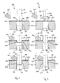
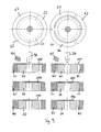
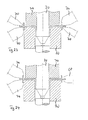
- FIGS. 1 and 2 show basic aspects of the method according to the invention and the device 10 according to the invention by the example of the non-cutting shaping of a cup or a hub to a preferably substantially rotationally symmetrical workpiece 100, for example a blank or preform.
- the apparatus 10 for reshaping the workpiece 100 has a die 20 with an approximately central receiving opening 22 into which a ram 30 can be inserted linearly in an axial direction.
- the die 20 and the punch 30 are matched to one another such that a drawing gap is formed between them, in which an inner region 102 of the workpiece 100 is pulled into the die 20 when the punch 30 is retracted.
- Die 20 and punch 30 are rotatably mounted about a rotation axis 12 on a machine bed, not shown, and rotationally driven.
- the workpiece 100 can be positioned on the die 20 and can also be rotated about it.
- the workpiece 100 is optionally centered on the die 20 and is held in position by the die 20 and the punch 30 during the forming.
- For a particularly effective forming of the punch 30 can be driven in addition to the die 20 speed or rotational angle synchronous.
- the apparatus 10 comprises one or more forming rollers 40 which are adapted to an outer, substantially radially extending Area 104 of the workpiece 100 to be delivered axially and / or radially, while the inner portion 102 of the workpiece 100 by means of the punch 30 and the die 20 is transformed.
- the at least one forming roller 40 is rotatably mounted about an axis of rotation 42 which preferably extends transversely or obliquely to the axis of rotation 12.
- the die 20 has a pressing surface 24 which extends substantially transverse to the axis of rotation 12 and is mounted on a shaft 14.
- the die 20 For forming the workpiece 100, this is arranged on the die 20.
- the punch 30 is moved axially along the axis of rotation 12 or coaxially with the axis of rotation 12 in the direction of the die 20, so that the workpiece 100 is clamped between the die 20 and the punch 30.
- Die 20 and punch 30 are rotated about the axis of rotation 12, which also represents a center axis 112 of the workpiece, in rotation.
- the workpiece 100 is also rotated via the die 20 in rotation.
- stamp 30 and die 20 are arranged and guided centric or coaxial with each other.
- a compressive and / or tensile stress acts on the workpiece 100.
- a forming roller 40 is delivered to the radially outer portion 104 of the workpiece 100 and actively causes a flow of material from the radially outer portion 104 in the direction of the radially inner portion 102.
- Umformrolle 40 is in the formed area material in shifted radial and / or axial direction and reduces an axial thickness of the area 104.
- the forming roller 40 in particular pushes material radially inwards and leads this to the drawing gap.
- the forming roller 40 is preferably to move radially inward, like the Figures 1.b and 1.c respectively 2.b and 2.c can be seen.
- forming roller 40 in particular spinning roller or pressure roller, a compressive stress and / or tensile stress is exerted on the workpiece 100 to be formed, which supports the flow of material during the forming process of the punch 30.
- the deformation of the workpiece 100 thus takes place by a combination of a deep-drawing process and an axial and / or radial flow-forming process.
- Fig. 1 shows an inventive method and components of the device according to the invention using the example of the forming of a ronde-shaped workpiece 100 to a component having an axial mold portion 106 in the form of a cup-shaped inner region.
- the punch 30 has a preferably substantially cylindrical shape with a cylindrical outer surface 32.
- Fig. 2 shows an embodiment of the method according to the invention based on the deformation of a substantially circular-shaped workpiece 100 with a central center opening 110 to a component with an axial shape portion 106 in the form of a sleeve-shaped inner region.
- the punch 30 has an approximately conical portion 34 for expanding the workpiece 100 and an inserting portion 35 for inserting and centering the workpiece 100.
- the insertion section 35 is first inserted into the center central opening 110 of the workpiece 100.
- the punch 30 is retracted into the receiving opening 22 and the workpiece 100 drawn into the drawing gap between the die 20 and punch 30, wherein the center opening 110 is widened.
- the radially outer region 104 is acted upon by a forming roller 40, thus producing a targeted flow of material in the direction of the drawing gap.
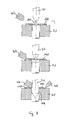
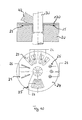
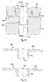
- Fig. 3 1 shows an embodiment of the method in which the workpiece 100 is preformed by the forming roller 40 before the draw forming of the radially inner region 102 and the workpiece 100 is centered on the die 20.
- the centering takes place by pressing the workpiece 100 into a contour of the die 20.
- the outer region of the workpiece 100 is pressed into an annular groove in the die 20.
- the preforming of the radially outer region 104 of the workpiece 100 fixes the workpiece 100 in the radial direction on the die 20.
- the radial extent of the workpiece 100 remains unchanged due to the circumferential profile of the region 104. This results in the pulling of the workpiece 100 particularly large pulling forces that without applying the radial Outer portion 104 during drawing forming would mean a loss of centering and / or a significant risk of fracture of the workpiece 100.
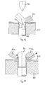
- Fig. 4 shows another way to fix the workpiece to the die 20.
- the die 20 comprises an outer peripheral region 26, which is angled in relation to an inner surface section against which the workpiece 100 rests.
- the workpiece 100 is applied to form an approximately annular kink on the outer peripheral portion 26 of the die 20.
- the workpiece 100 can be fixed by means of a hold-down ring 28, wherein the workpiece 100 is clamped between the die 20 and the hold-down ring 28.
- the radially inner portion 102 of the workpiece 100 as described above, formed by drawing, wherein at the same time the radially outer portion 104 is applied by the forming roller 40 or deformed.
- a hold-down roller 66 is shown which holds down the workpiece 100 in the axial direction and prevents the workpiece 100 or material from rearing up.
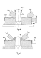
- Fig. 5 corresponds essentially to the representation of the Figures 1.b respectively 2 B , wherein the punch 30 is additionally supported by a support roller 54.
- the support roller 54 is rotatably supported substantially parallel to the punch 30 and bears against a peripheral surface of the punch 30. It can also be arranged distributed around the punch 30 in the circumferential direction a plurality of support rollers 54.
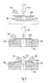
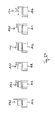
- FIGS. 6 to 8 show ways to limit or prevent material flow to the outside when forming the outer region 104 and / or support.
- a pressure roller 68 is arranged, which presses the workpiece 100 radially inwardly.
- a material flow is prevented to the outside and generated by the action of the forming roller 40, a substantially exclusively radially inward material flow.
- the radial material flow can be supported by the radial displacement of the roller 68.
- An axial upsetting of the material in the outer region 104 is prevented or minimized by the paired use of the rollers 66 and 67.
- Fig. 7 shows to prevent a flow of material to the outside a support ring 60 which is arranged around the workpiece 100. An outer peripheral portion of the workpiece 100 abuts on the support ring 60.
- Fig. 8 shows a further embodiment of a pressure roller 68, which in contrast to the in Fig. 6 illustrated design has a chamber, which fixes the workpiece 100 in the axial direction and / or can be used for targeted thickening of the outer radial portion 104.
- FIGS. 6 and 8 2 further show a hold-down roller 66 above the workpiece 100 and a counter-roller 67 on a side of the workpiece 100 opposite the hold-down roller 66, next to the die 20.
- the rollers 66 and 67 can limit the axial material flow in the region 104.
- FIG Fig. 9 An embodiment of a support ring 60 is shown in FIG Fig. 9 shown.
- the support ring 60 includes a plurality of ring segments 62, which are each arranged radially displaceable. By radially inwardly moving the ring segments 62, the workpiece 100 can be clamped or supported, as in the respective lower representations of Fig. 9 is shown.
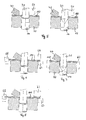
- Fig. 10 1 illustrates a possibility of introducing a defined structure into the radially outer region 104 of the workpiece 100.
- the die 20 comprises on its pressing surface 24 a correspondingly defined structure 25 with a plurality of structural elements, for example for forming stiffening ribs, reinforcing points or a toothing on the radially outer region 104 of the workpiece 100.
- the structural elements can in principle be arranged arbitrarily, although not one -rotation symmetric arrangement is possible.
- FIGS. 11 to 13 show possibilities of shaping a contour or profiling on the radially inner region 102 of the workpiece 100 Fig. 11
- the die 20 has at its receiving opening 22 a defined contour 23 in the form of a profiling into which the material is pressed during drawing, so that a profiled or corrugated axial section of the workpiece 100 can be formed.
- the punch 30 in Fig. 12 a structured outer contour 33, through which a structured region can be introduced into the axial section of the workpiece 100.
- polygonal contours 118 are formed as in FIG Fig. 13 shown.
- Fig. 14 shows an embodiment of the method in which the material is drawn while pulling. As a result, the material thickness in the drawing region or the axial shaping section 106 of the workpiece 100 can be reduced to a desired thickness.
- an ironing 56 is introduced, which surrounds the receiving opening 22 annular and has a Abstreckabexcellent whose diameter is less than the diameter of the receiving opening 22.
- On the left side of the Fig. 14 is a stage of the process at the beginning of the forming and on the right side of a process stage with completed drawing process shown.
- Fig. 15 shows an embodiment in which the shaft 14 and the pusher is designed as a counter punch.
- a bottom portion 114 can be contoured in the pull portion of the workpiece 100.
- punches 30 and counter punches each comprise an axial end face which corresponds to the contour of the finished shaped workpiece 100.
- FIGS. 16 to 27 show further forming steps that can be carried out in particular after the drawing process.
- Fig. 16 an embodiment in which the workpiece 100 remains after the drawing process between the die 20 and punch 30 on the die 20 and the punch 30 is withdrawn.
- a Nachformrolle 70 which is designed in the present case as an inner roller, the axial shape portion 106 of the workpiece 100 can be reshaped, in particular be stretched. At this time, the inner diameter of the mold section 106 is reduced.
- the radially outer portion 104 of the workpiece 100 may be urged by the forming roll 40 to push additional material into the axial forming portion 106.
- Fig. 17 shows a way to form on the axial shape portion 106 of the workpiece 100 axially opposite side, a second axial mold portion 106.
- a forming roller 40a, 40b further material from the radially outer portion 104 is displaced inwardly and integrally formed on the punch 30.
- the punch and / or the forming roller 40a, 40b have a chamber 38.
- the forming rollers 40a, 40b may in principle also be the same forming roller 40 used during the drawing operation.
- FIGS. 18 and 19 the use of a sliding sleeve 74 is shown in order to further increase the flexibility of the method and to be able to produce complex components.
- the sliding sleeve 74 is arranged annularly around the punch 30 and axially displaceable relative to the punch 30.
- the sliding sleeve 74 may be retracted to allow the forming roller 40 to be moved up to the punch 30 to effectively move material radially inward toward the drawing nip.
- the sliding sleeve 74 can be axially moved up to the workpiece 100 to form a spinning mandrel for a second axial section, as in Fig. 19 shown.
- the radial extent of the sliding sleeve 74 is in principle freely selectable, so that a very wide variety of shapes of the workpiece 100 can be produced.
- FIGS. 23 and 24 Further Nachform suitse are shown to form an outer region of the workpiece 100.
- the die 20 and a sliding sleeve 74 serve as spinning mandrels against the outer peripheries material is pressed.
- Fig. 25 shows a complex component which can be produced by the method according to the invention. To form multiple hub sections different sliding sleeves 74 are used.
- FIG. 12 shows the upset of a hub of a workpiece 100 as a follow-up of the manufacture of the hub by drawing and simultaneously forming the flange portion 108.
- Fig. 27 shows further examples of components that can be produced by forming a workpiece 100 by means of the method according to the invention and the device according to the invention.
Landscapes
- Engineering & Computer Science (AREA)
- Mechanical Engineering (AREA)
- Shaping Metal By Deep-Drawing, Or The Like (AREA)
Priority Applications (7)
| Application Number | Priority Date | Filing Date | Title |
|---|---|---|---|
| EP12002781.8A EP2653244B1 (fr) | 2012-04-20 | 2012-04-20 | Procédé et dispositif pour le formage d'une pièce |
| ES12002781.8T ES2532217T3 (es) | 2012-04-20 | 2012-04-20 | Procedimiento y dispositivo para la conformación de una pieza de trabajo |
| JP2015506133A JP6131317B2 (ja) | 2012-04-20 | 2013-03-05 | ワークピースを再成形するための方法およびデバイス |
| US14/394,529 US9669445B2 (en) | 2012-04-20 | 2013-03-05 | Method and device for reshaping a workpiece by displacing material in the workpiece |
| CN201380020971.6A CN104395008B (zh) | 2012-04-20 | 2013-03-05 | 用于对工件进行再成形的方法和装置 |
| KR1020147029327A KR101910395B1 (ko) | 2012-04-20 | 2013-03-05 | 워크피스의 재형성 방법 및 장치 |
| PCT/EP2013/054388 WO2013156193A1 (fr) | 2012-04-20 | 2013-03-05 | Procédé et dispositif de formage d'une pièce |
Applications Claiming Priority (1)
| Application Number | Priority Date | Filing Date | Title |
|---|---|---|---|
| EP12002781.8A EP2653244B1 (fr) | 2012-04-20 | 2012-04-20 | Procédé et dispositif pour le formage d'une pièce |
Publications (2)
| Publication Number | Publication Date |
|---|---|
| EP2653244A1 true EP2653244A1 (fr) | 2013-10-23 |
| EP2653244B1 EP2653244B1 (fr) | 2014-12-17 |
Family
ID=48141902
Family Applications (1)
| Application Number | Title | Priority Date | Filing Date |
|---|---|---|---|
| EP12002781.8A Active EP2653244B1 (fr) | 2012-04-20 | 2012-04-20 | Procédé et dispositif pour le formage d'une pièce |
Country Status (7)
| Country | Link |
|---|---|
| US (1) | US9669445B2 (fr) |
| EP (1) | EP2653244B1 (fr) |
| JP (1) | JP6131317B2 (fr) |
| KR (1) | KR101910395B1 (fr) |
| CN (1) | CN104395008B (fr) |
| ES (1) | ES2532217T3 (fr) |
| WO (1) | WO2013156193A1 (fr) |
Cited By (2)
| Publication number | Priority date | Publication date | Assignee | Title |
|---|---|---|---|---|
| WO2016079024A1 (fr) | 2014-11-17 | 2016-05-26 | Wf-Maschinenbau Und Blechformtechnik Gmbh & Co. Kg | Procédé de fabrication d'un élément moulé à symétrie de révolution |
| EP3736920A1 (fr) * | 2019-05-06 | 2020-11-11 | Nexans | Borne de contact et son procédé de fabrication |
Families Citing this family (9)
| Publication number | Priority date | Publication date | Assignee | Title |
|---|---|---|---|---|
| WO2014196127A1 (fr) * | 2013-06-04 | 2014-12-11 | 川崎重工業株式会社 | Procédé d'épaississement et de formage par rotation et dispositif pour l'épaississement et le formage par rotation |
| JP6445779B2 (ja) | 2014-04-21 | 2018-12-26 | 川崎重工業株式会社 | 予備成形体および軸対称部品の製造方法 |
| DE102016205492A1 (de) * | 2016-04-04 | 2017-10-05 | Thyssenkrupp Ag | Verfahren und Vorrichtung zum Umformen eines Halbzeugs |
| CN106514154B (zh) * | 2016-12-12 | 2018-12-28 | 南通福乐达汽车配件有限公司 | 一种曲轴硅油减震器壳体的整体旋压成型方法 |
| DE102018208820A1 (de) * | 2018-06-05 | 2019-12-05 | BSH Hausgeräte GmbH | Elektrischer Antriebsmotor, Nassläufer-Pumpe und Haushaltsgerät |
| CN108723190B (zh) * | 2018-07-21 | 2024-03-22 | 扬州广菱电子有限公司 | 一种齿状载体补强连续模结构 |
| EP3856429A4 (fr) * | 2018-09-27 | 2022-06-22 | Inno-Spin LLC | Procédés, systèmes et produits de formation de rouleaux multiaxes |
| CN114227161B (zh) * | 2021-12-15 | 2023-04-28 | 中国航发动力股份有限公司 | 一种燃烧室内壳体的整体成形方法 |
| CN117753860A (zh) * | 2023-12-21 | 2024-03-26 | 镇江先锋汽车零部件有限公司 | 一种机壳产品材料的定向流动拉伸方法 |
Citations (5)
| Publication number | Priority date | Publication date | Assignee | Title |
|---|---|---|---|---|
| DE4400257C1 (de) | 1993-12-09 | 1994-12-01 | Wf Maschinenbau Blechformtech | Drückverfahren zur spanlosen Herstellung einer Nabe eines die Nabe aufweisenden Getriebeteiles |
| DE4327746A1 (de) | 1993-08-18 | 1995-02-23 | Herzing & Schroth Gmbh & Co Kg | Verfahren zum Herstellen eines rotationssymmetrischen Körpers |
| EP0997210A2 (fr) | 1998-10-29 | 2000-05-03 | Leico GmbH & Co. Werkzeugmaschinenbau | Procédé de fabrication d'objets en forme de disque avec moyeu et rouleau de pression pour exécuter ledit procédé |
| EP1136150A2 (fr) * | 2000-03-14 | 2001-09-26 | Nissan Motor Co., Ltd. | Méthode de formage d' une projection intégrale dans une pièce par fluotournage et article produit par cette méthode |
| DE10061403A1 (de) * | 2000-12-09 | 2002-06-27 | Wf Maschinenbau Blechformtech | Verfahren zur Herstellung eines rotationssymmetrischen Formkörpers |
Family Cites Families (13)
| Publication number | Priority date | Publication date | Assignee | Title |
|---|---|---|---|---|
| US3120206A (en) * | 1959-03-09 | 1964-02-04 | Lodge & Shipley Co | Metal working |
| US5031296A (en) * | 1990-05-14 | 1991-07-16 | S.C. S.R.L. | Machine tool for manufacturing pulleys or wheels |
| EP0725693B1 (fr) * | 1993-12-09 | 1997-07-30 | Wf-Maschinenbau Und Blechformtechnik Gmbh & Co. Kg | Procedes de realisation sans enlevement de copeaux d'un moyeu d'organe de transmission |
| JPH08174114A (ja) * | 1994-12-20 | 1996-07-09 | Shin Kobe Electric Mach Co Ltd | 円筒形電池缶の成形法 |
| US5947853A (en) * | 1996-08-15 | 1999-09-07 | The Gates Corporation | Spun pulley with thick hub |
| JP2002122209A (ja) * | 2000-10-11 | 2002-04-26 | Exedy Corp | 流体式回転羽根車用シェル、その製造方法及び流体式回転羽根車 |
| JP2002122210A (ja) * | 2000-10-11 | 2002-04-26 | Exedy Corp | 流体式トルク伝達装置のタービンシェル及びその製造方法 |
| JP4066239B2 (ja) * | 2002-06-28 | 2008-03-26 | 関西ティー・エル・オー株式会社 | 深絞り加工装置 |
| JP4781137B2 (ja) * | 2006-03-20 | 2011-09-28 | 株式会社Neomaxマテリアル | プレス成形用クラッド材及びそのクラッド材によってプレス成形されたシームレス缶 |
| DE102006039656B4 (de) * | 2006-08-24 | 2008-12-18 | Leifeld Metal Spinning Gmbh | Vorrichtung und Verfahren zum Herstellen eines Hohlkörpers aus einem rondenförmigen Werkstück |
| JP2008260042A (ja) | 2007-04-12 | 2008-10-30 | Enami Seiki:Kk | プレス成形装置 |
| CN100589896C (zh) | 2007-07-10 | 2010-02-17 | 柳州市龙杰汽车配件有限责任公司 | 一种不等径钣制旋压皮带轮的连续旋压成型方法 |
| JP2010214449A (ja) * | 2009-03-18 | 2010-09-30 | Nippon Spindle Mfg Co Ltd | 塑性加工装置及び塑性加工方法 |
-
2012
- 2012-04-20 ES ES12002781.8T patent/ES2532217T3/es active Active
- 2012-04-20 EP EP12002781.8A patent/EP2653244B1/fr active Active
-
2013
- 2013-03-05 JP JP2015506133A patent/JP6131317B2/ja active Active
- 2013-03-05 WO PCT/EP2013/054388 patent/WO2013156193A1/fr active Application Filing
- 2013-03-05 US US14/394,529 patent/US9669445B2/en active Active
- 2013-03-05 KR KR1020147029327A patent/KR101910395B1/ko active IP Right Grant
- 2013-03-05 CN CN201380020971.6A patent/CN104395008B/zh not_active Expired - Fee Related
Patent Citations (5)
| Publication number | Priority date | Publication date | Assignee | Title |
|---|---|---|---|---|
| DE4327746A1 (de) | 1993-08-18 | 1995-02-23 | Herzing & Schroth Gmbh & Co Kg | Verfahren zum Herstellen eines rotationssymmetrischen Körpers |
| DE4400257C1 (de) | 1993-12-09 | 1994-12-01 | Wf Maschinenbau Blechformtech | Drückverfahren zur spanlosen Herstellung einer Nabe eines die Nabe aufweisenden Getriebeteiles |
| EP0997210A2 (fr) | 1998-10-29 | 2000-05-03 | Leico GmbH & Co. Werkzeugmaschinenbau | Procédé de fabrication d'objets en forme de disque avec moyeu et rouleau de pression pour exécuter ledit procédé |
| EP1136150A2 (fr) * | 2000-03-14 | 2001-09-26 | Nissan Motor Co., Ltd. | Méthode de formage d' une projection intégrale dans une pièce par fluotournage et article produit par cette méthode |
| DE10061403A1 (de) * | 2000-12-09 | 2002-06-27 | Wf Maschinenbau Blechformtech | Verfahren zur Herstellung eines rotationssymmetrischen Formkörpers |
Cited By (4)
| Publication number | Priority date | Publication date | Assignee | Title |
|---|---|---|---|---|
| WO2016079024A1 (fr) | 2014-11-17 | 2016-05-26 | Wf-Maschinenbau Und Blechformtechnik Gmbh & Co. Kg | Procédé de fabrication d'un élément moulé à symétrie de révolution |
| KR20170092584A (ko) * | 2014-11-17 | 2017-08-11 | 베에프-마쉰넨바우 운트 블레히포름테크닉 게엠베하 운트 컴파니 카게 | 회전 대칭 성형품을 제조하기 위한 방법 |
| EP3221068B1 (fr) * | 2014-11-17 | 2021-04-14 | WF Maschinenbau- und Blechformtechnik GmbH & Co. KG | Procédé de fabrication d'un élément moulé à symétrie de révolution |
| EP3736920A1 (fr) * | 2019-05-06 | 2020-11-11 | Nexans | Borne de contact et son procédé de fabrication |
Also Published As
| Publication number | Publication date |
|---|---|
| JP6131317B2 (ja) | 2017-05-17 |
| EP2653244B1 (fr) | 2014-12-17 |
| JP2015514588A (ja) | 2015-05-21 |
| WO2013156193A1 (fr) | 2013-10-24 |
| CN104395008B (zh) | 2016-05-25 |
| US20150089986A1 (en) | 2015-04-02 |
| KR20150007288A (ko) | 2015-01-20 |
| US9669445B2 (en) | 2017-06-06 |
| CN104395008A (zh) | 2015-03-04 |
| ES2532217T3 (es) | 2015-03-25 |
| KR101910395B1 (ko) | 2018-10-22 |
Similar Documents
| Publication | Publication Date | Title |
|---|---|---|
| EP2653244B1 (fr) | Procédé et dispositif pour le formage d'une pièce | |
| EP2127775B1 (fr) | Procédé et maschine de fluotournage pour la fabrication de pièces | |
| DE19861391B4 (de) | Verfahren zum Formen einer Nabenscheibe und Drückrolle zur Verwendung beim Formen einer Nabenscheibe | |
| DE2927755A1 (de) | Verfahren zum ziehen eines duennwandigen konischen behaelters sowie vorrichtung zum durchfuehren des verfahrens | |
| EP1108483B1 (fr) | Procédé et dispositif pour le fluotournage | |
| DE10005578C2 (de) | Verfahren und Drückwalzvorrichtung zum Herstellen eines Hohlkörpers | |
| EP0955110B1 (fr) | Procédé et dispositif pour le fluotournage | |
| DE19723073C2 (de) | Verfahren zur Herstellung eines rotationssymmetrischen Werkstücks | |
| DE102009001305B4 (de) | Verfahren zur Herstellung eines Profils an einem Blechteil, Vorrichtung zur Durchführung des Verfahrens sowie Blechteil, herstellbar nach dem Verfahren | |
| EP0997210B1 (fr) | Procédé de fabrication d'objets en forme de disque avec moyeu et rouleau de pression pour exécuter ledit procédé | |
| DE4032424C2 (de) | Verfahren und Vorrichtung zur Herstellung von gefalzten Rohren | |
| DE102015108768A1 (de) | Verfahren und Vorrichtung zur Erzielung von großen Kragenlängen | |
| EP3246104B1 (fr) | Procede et dispositif de fabrication d'une piece de formage | |
| DE19849981C2 (de) | Verfahren zum Formen eines scheibenförmigen Teiles mit Nabe und Drückrolle für das Verfahren | |
| DE102010011809B4 (de) | Verfahren und Drückwalz- und Profiliermaschine zum Herstellen eines rotationssymmetrischen Werkstückes sowie Profilrolle hierfür | |
| DE19632279C2 (de) | Verfahren zur Herstellung eines scheibenförmigen Teiles | |
| DE19724657C2 (de) | Verfahren und Vorrichtung zum Herstellen eines rotationssymmetrischen Körpers | |
| DE102015114317A1 (de) | Auskragen mit großer Kragenwanddicke | |
| DE19946508C2 (de) | Verfahren zum Herstellen einer Welle mit durchmessergrößerem Flansch | |
| EP1163961B2 (fr) | Procédé et dispositif de fabrication d'un élement de transmission | |
| EP1362652B1 (fr) | Méthode et dispositif de fluotournage pour le formage d' un moyeu sans enlèvement de copeaux | |
| DE10121546A1 (de) | Verfahren und Drückrolle zum Anformen einer Nabe | |
| EP2506996B1 (fr) | Procédé et dispositif de production d'une pièce façonnée présentant un trou traversant | |
| EP1382404B1 (fr) | Méthode, rouleau et machine de fluotournage pour le formage d' un moyeu cylindrique sans enlèvement de copeaux | |
| EP2604358B1 (fr) | Procédé de fabrication d'une pièce usinée en tôle en forme de pot |
Legal Events
| Date | Code | Title | Description |
|---|---|---|---|
| PUAI | Public reference made under article 153(3) epc to a published international application that has entered the european phase |
Free format text: ORIGINAL CODE: 0009012 |
|
| 17P | Request for examination filed |
Effective date: 20120827 |
|
| AK | Designated contracting states |
Kind code of ref document: A1 Designated state(s): AL AT BE BG CH CY CZ DE DK EE ES FI FR GB GR HR HU IE IS IT LI LT LU LV MC MK MT NL NO PL PT RO RS SE SI SK SM TR |
|
| AX | Request for extension of the european patent |
Extension state: BA ME |
|
| RBV | Designated contracting states (corrected) |
Designated state(s): AL AT BE BG CH CY CZ DE DK EE ES FI FR GB GR HR HU IE IS IT LI LT LU LV MC MK MT NL NO PL PT RO RS SE SI SK SM TR |
|
| GRAP | Despatch of communication of intention to grant a patent |
Free format text: ORIGINAL CODE: EPIDOSNIGR1 |
|
| INTG | Intention to grant announced |
Effective date: 20140718 |
|
| GRAS | Grant fee paid |
Free format text: ORIGINAL CODE: EPIDOSNIGR3 |
|
| GRAA | (expected) grant |
Free format text: ORIGINAL CODE: 0009210 |
|
| AK | Designated contracting states |
Kind code of ref document: B1 Designated state(s): AL AT BE BG CH CY CZ DE DK EE ES FI FR GB GR HR HU IE IS IT LI LT LU LV MC MK MT NL NO PL PT RO RS SE SI SK SM TR |
|
| REG | Reference to a national code |
Ref country code: GB Ref legal event code: FG4D Free format text: NOT ENGLISH |
|
| REG | Reference to a national code |
Ref country code: CH Ref legal event code: EP |
|
| REG | Reference to a national code |
Ref country code: IE Ref legal event code: FG4D Free format text: LANGUAGE OF EP DOCUMENT: GERMAN |
|
| REG | Reference to a national code |
Ref country code: AT Ref legal event code: REF Ref document number: 701509 Country of ref document: AT Kind code of ref document: T Effective date: 20150115 |
|
| REG | Reference to a national code |
Ref country code: DE Ref legal event code: R096 Ref document number: 502012001801 Country of ref document: DE Effective date: 20150129 |
|
| REG | Reference to a national code |
Ref country code: ES Ref legal event code: FG2A Ref document number: 2532217 Country of ref document: ES Kind code of ref document: T3 Effective date: 20150325 |
|
| REG | Reference to a national code |
Ref country code: FR Ref legal event code: PLFP Year of fee payment: 4 |
|
| PG25 | Lapsed in a contracting state [announced via postgrant information from national office to epo] |
Ref country code: NO Free format text: LAPSE BECAUSE OF FAILURE TO SUBMIT A TRANSLATION OF THE DESCRIPTION OR TO PAY THE FEE WITHIN THE PRESCRIBED TIME-LIMIT Effective date: 20150317 Ref country code: LT Free format text: LAPSE BECAUSE OF FAILURE TO SUBMIT A TRANSLATION OF THE DESCRIPTION OR TO PAY THE FEE WITHIN THE PRESCRIBED TIME-LIMIT Effective date: 20141217 Ref country code: FI Free format text: LAPSE BECAUSE OF FAILURE TO SUBMIT A TRANSLATION OF THE DESCRIPTION OR TO PAY THE FEE WITHIN THE PRESCRIBED TIME-LIMIT Effective date: 20141217 |
|
| REG | Reference to a national code |
Ref country code: LT Ref legal event code: MG4D |
|
| PG25 | Lapsed in a contracting state [announced via postgrant information from national office to epo] |
Ref country code: SE Free format text: LAPSE BECAUSE OF FAILURE TO SUBMIT A TRANSLATION OF THE DESCRIPTION OR TO PAY THE FEE WITHIN THE PRESCRIBED TIME-LIMIT Effective date: 20141217 Ref country code: LV Free format text: LAPSE BECAUSE OF FAILURE TO SUBMIT A TRANSLATION OF THE DESCRIPTION OR TO PAY THE FEE WITHIN THE PRESCRIBED TIME-LIMIT Effective date: 20141217 Ref country code: HR Free format text: LAPSE BECAUSE OF FAILURE TO SUBMIT A TRANSLATION OF THE DESCRIPTION OR TO PAY THE FEE WITHIN THE PRESCRIBED TIME-LIMIT Effective date: 20141217 Ref country code: GR Free format text: LAPSE BECAUSE OF FAILURE TO SUBMIT A TRANSLATION OF THE DESCRIPTION OR TO PAY THE FEE WITHIN THE PRESCRIBED TIME-LIMIT Effective date: 20150318 Ref country code: RS Free format text: LAPSE BECAUSE OF FAILURE TO SUBMIT A TRANSLATION OF THE DESCRIPTION OR TO PAY THE FEE WITHIN THE PRESCRIBED TIME-LIMIT Effective date: 20141217 |
|
| PG25 | Lapsed in a contracting state [announced via postgrant information from national office to epo] |
Ref country code: NL Free format text: LAPSE BECAUSE OF FAILURE TO SUBMIT A TRANSLATION OF THE DESCRIPTION OR TO PAY THE FEE WITHIN THE PRESCRIBED TIME-LIMIT Effective date: 20141217 |
|
| PG25 | Lapsed in a contracting state [announced via postgrant information from national office to epo] |
Ref country code: EE Free format text: LAPSE BECAUSE OF FAILURE TO SUBMIT A TRANSLATION OF THE DESCRIPTION OR TO PAY THE FEE WITHIN THE PRESCRIBED TIME-LIMIT Effective date: 20141217 Ref country code: RO Free format text: LAPSE BECAUSE OF FAILURE TO SUBMIT A TRANSLATION OF THE DESCRIPTION OR TO PAY THE FEE WITHIN THE PRESCRIBED TIME-LIMIT Effective date: 20141217 Ref country code: CZ Free format text: LAPSE BECAUSE OF FAILURE TO SUBMIT A TRANSLATION OF THE DESCRIPTION OR TO PAY THE FEE WITHIN THE PRESCRIBED TIME-LIMIT Effective date: 20141217 Ref country code: SK Free format text: LAPSE BECAUSE OF FAILURE TO SUBMIT A TRANSLATION OF THE DESCRIPTION OR TO PAY THE FEE WITHIN THE PRESCRIBED TIME-LIMIT Effective date: 20141217 |
|
| PG25 | Lapsed in a contracting state [announced via postgrant information from national office to epo] |
Ref country code: PL Free format text: LAPSE BECAUSE OF FAILURE TO SUBMIT A TRANSLATION OF THE DESCRIPTION OR TO PAY THE FEE WITHIN THE PRESCRIBED TIME-LIMIT Effective date: 20141217 Ref country code: IS Free format text: LAPSE BECAUSE OF FAILURE TO SUBMIT A TRANSLATION OF THE DESCRIPTION OR TO PAY THE FEE WITHIN THE PRESCRIBED TIME-LIMIT Effective date: 20150417 |
|
| REG | Reference to a national code |
Ref country code: DE Ref legal event code: R097 Ref document number: 502012001801 Country of ref document: DE |
|
| PLBE | No opposition filed within time limit |
Free format text: ORIGINAL CODE: 0009261 |
|
| STAA | Information on the status of an ep patent application or granted ep patent |
Free format text: STATUS: NO OPPOSITION FILED WITHIN TIME LIMIT |
|
| PG25 | Lapsed in a contracting state [announced via postgrant information from national office to epo] |
Ref country code: DK Free format text: LAPSE BECAUSE OF FAILURE TO SUBMIT A TRANSLATION OF THE DESCRIPTION OR TO PAY THE FEE WITHIN THE PRESCRIBED TIME-LIMIT Effective date: 20141217 |
|
| 26N | No opposition filed |
Effective date: 20150918 |
|
| PG25 | Lapsed in a contracting state [announced via postgrant information from national office to epo] |
Ref country code: LU Free format text: LAPSE BECAUSE OF FAILURE TO SUBMIT A TRANSLATION OF THE DESCRIPTION OR TO PAY THE FEE WITHIN THE PRESCRIBED TIME-LIMIT Effective date: 20150420 Ref country code: MC Free format text: LAPSE BECAUSE OF FAILURE TO SUBMIT A TRANSLATION OF THE DESCRIPTION OR TO PAY THE FEE WITHIN THE PRESCRIBED TIME-LIMIT Effective date: 20141217 |
|
| REG | Reference to a national code |
Ref country code: CH Ref legal event code: PL |
|
| PG25 | Lapsed in a contracting state [announced via postgrant information from national office to epo] |
Ref country code: IT Free format text: LAPSE BECAUSE OF FAILURE TO SUBMIT A TRANSLATION OF THE DESCRIPTION OR TO PAY THE FEE WITHIN THE PRESCRIBED TIME-LIMIT Effective date: 20141217 |
|
| REG | Reference to a national code |
Ref country code: IE Ref legal event code: MM4A |
|
| PG25 | Lapsed in a contracting state [announced via postgrant information from national office to epo] |
Ref country code: LI Free format text: LAPSE BECAUSE OF NON-PAYMENT OF DUE FEES Effective date: 20150430 Ref country code: CH Free format text: LAPSE BECAUSE OF NON-PAYMENT OF DUE FEES Effective date: 20150430 |
|
| PG25 | Lapsed in a contracting state [announced via postgrant information from national office to epo] |
Ref country code: SI Free format text: LAPSE BECAUSE OF FAILURE TO SUBMIT A TRANSLATION OF THE DESCRIPTION OR TO PAY THE FEE WITHIN THE PRESCRIBED TIME-LIMIT Effective date: 20141217 |
|
| PG25 | Lapsed in a contracting state [announced via postgrant information from national office to epo] |
Ref country code: IE Free format text: LAPSE BECAUSE OF NON-PAYMENT OF DUE FEES Effective date: 20150420 |
|
| REG | Reference to a national code |
Ref country code: FR Ref legal event code: PLFP Year of fee payment: 5 |
|
| GBPC | Gb: european patent ceased through non-payment of renewal fee |
Effective date: 20160420 |
|
| PG25 | Lapsed in a contracting state [announced via postgrant information from national office to epo] |
Ref country code: MT Free format text: LAPSE BECAUSE OF FAILURE TO SUBMIT A TRANSLATION OF THE DESCRIPTION OR TO PAY THE FEE WITHIN THE PRESCRIBED TIME-LIMIT Effective date: 20141217 |
|
| PG25 | Lapsed in a contracting state [announced via postgrant information from national office to epo] |
Ref country code: GB Free format text: LAPSE BECAUSE OF NON-PAYMENT OF DUE FEES Effective date: 20160420 |
|
| REG | Reference to a national code |
Ref country code: FR Ref legal event code: PLFP Year of fee payment: 6 |
|
| PG25 | Lapsed in a contracting state [announced via postgrant information from national office to epo] |
Ref country code: HU Free format text: LAPSE BECAUSE OF FAILURE TO SUBMIT A TRANSLATION OF THE DESCRIPTION OR TO PAY THE FEE WITHIN THE PRESCRIBED TIME-LIMIT; INVALID AB INITIO Effective date: 20120420 Ref country code: SM Free format text: LAPSE BECAUSE OF FAILURE TO SUBMIT A TRANSLATION OF THE DESCRIPTION OR TO PAY THE FEE WITHIN THE PRESCRIBED TIME-LIMIT Effective date: 20141217 Ref country code: BG Free format text: LAPSE BECAUSE OF FAILURE TO SUBMIT A TRANSLATION OF THE DESCRIPTION OR TO PAY THE FEE WITHIN THE PRESCRIBED TIME-LIMIT Effective date: 20141217 |
|
| PG25 | Lapsed in a contracting state [announced via postgrant information from national office to epo] |
Ref country code: CY Free format text: LAPSE BECAUSE OF FAILURE TO SUBMIT A TRANSLATION OF THE DESCRIPTION OR TO PAY THE FEE WITHIN THE PRESCRIBED TIME-LIMIT Effective date: 20141217 |
|
| PG25 | Lapsed in a contracting state [announced via postgrant information from national office to epo] |
Ref country code: BE Free format text: LAPSE BECAUSE OF NON-PAYMENT OF DUE FEES Effective date: 20150430 Ref country code: PT Free format text: LAPSE BECAUSE OF FAILURE TO SUBMIT A TRANSLATION OF THE DESCRIPTION OR TO PAY THE FEE WITHIN THE PRESCRIBED TIME-LIMIT Effective date: 20150417 |
|
| REG | Reference to a national code |
Ref country code: DE Ref legal event code: R082 Ref document number: 502012001801 Country of ref document: DE Representative=s name: WUNDERLICH & HEIM PATENTANWAELTE PARTNERSCHAFT, DE |
|
| REG | Reference to a national code |
Ref country code: FR Ref legal event code: PLFP Year of fee payment: 7 |
|
| REG | Reference to a national code |
Ref country code: AT Ref legal event code: MM01 Ref document number: 701509 Country of ref document: AT Kind code of ref document: T Effective date: 20170420 |
|
| PG25 | Lapsed in a contracting state [announced via postgrant information from national office to epo] |
Ref country code: MK Free format text: LAPSE BECAUSE OF FAILURE TO SUBMIT A TRANSLATION OF THE DESCRIPTION OR TO PAY THE FEE WITHIN THE PRESCRIBED TIME-LIMIT Effective date: 20141217 |
|
| PG25 | Lapsed in a contracting state [announced via postgrant information from national office to epo] |
Ref country code: AT Free format text: LAPSE BECAUSE OF NON-PAYMENT OF DUE FEES Effective date: 20170420 |
|
| PGFP | Annual fee paid to national office [announced via postgrant information from national office to epo] |
Ref country code: FR Payment date: 20180424 Year of fee payment: 7 |
|
| PG25 | Lapsed in a contracting state [announced via postgrant information from national office to epo] |
Ref country code: AL Free format text: LAPSE BECAUSE OF FAILURE TO SUBMIT A TRANSLATION OF THE DESCRIPTION OR TO PAY THE FEE WITHIN THE PRESCRIBED TIME-LIMIT Effective date: 20141217 |
|
| PGFP | Annual fee paid to national office [announced via postgrant information from national office to epo] |
Ref country code: ES Payment date: 20190520 Year of fee payment: 8 |
|
| PGFP | Annual fee paid to national office [announced via postgrant information from national office to epo] |
Ref country code: TR Payment date: 20190508 Year of fee payment: 8 |
|
| PG25 | Lapsed in a contracting state [announced via postgrant information from national office to epo] |
Ref country code: FR Free format text: LAPSE BECAUSE OF NON-PAYMENT OF DUE FEES Effective date: 20190430 |
|
| REG | Reference to a national code |
Ref country code: DE Ref legal event code: R082 Ref document number: 502012001801 Country of ref document: DE Representative=s name: WUNDERLICH & HEIM PATENTANWAELTE PARTNERSCHAFT, DE Ref country code: DE Ref legal event code: R081 Ref document number: 502012001801 Country of ref document: DE Owner name: LEIFELD METAL SPINNING GMBH, DE Free format text: FORMER OWNER: LEIFELD METAL SPINNING AG, 59229 AHLEN, DE |
|
| REG | Reference to a national code |
Ref country code: ES Ref legal event code: FD2A Effective date: 20210903 |
|
| PG25 | Lapsed in a contracting state [announced via postgrant information from national office to epo] |
Ref country code: ES Free format text: LAPSE BECAUSE OF NON-PAYMENT OF DUE FEES Effective date: 20200421 |
|
| PG25 | Lapsed in a contracting state [announced via postgrant information from national office to epo] |
Ref country code: TR Free format text: LAPSE BECAUSE OF NON-PAYMENT OF DUE FEES Effective date: 20200420 |
|
| P01 | Opt-out of the competence of the unified patent court (upc) registered |
Effective date: 20230508 |
|
| PGFP | Annual fee paid to national office [announced via postgrant information from national office to epo] |
Ref country code: DE Payment date: 20230426 Year of fee payment: 12 |