EP2649257B1 - Schwenkbares horizontales und vertikales gerüstelement und verfahren zur errichtung einer versetzten arbeitsbühne - Google Patents
Schwenkbares horizontales und vertikales gerüstelement und verfahren zur errichtung einer versetzten arbeitsbühne Download PDFInfo
- Publication number
- EP2649257B1 EP2649257B1 EP12845108.5A EP12845108A EP2649257B1 EP 2649257 B1 EP2649257 B1 EP 2649257B1 EP 12845108 A EP12845108 A EP 12845108A EP 2649257 B1 EP2649257 B1 EP 2649257B1
- Authority
- EP
- European Patent Office
- Prior art keywords
- scaffold
- horizontal
- truss
- vertical
- connectors
- Prior art date
- Legal status (The legal status is an assumption and is not a legal conclusion. Google has not performed a legal analysis and makes no representation as to the accuracy of the status listed.)
- Active
Links
- 238000000034 method Methods 0.000 title claims description 17
- 230000008878 coupling Effects 0.000 claims description 5
- 238000010168 coupling process Methods 0.000 claims description 5
- 238000005859 coupling reaction Methods 0.000 claims description 5
- 210000002105 tongue Anatomy 0.000 description 12
- 210000005069 ears Anatomy 0.000 description 7
- 230000009471 action Effects 0.000 description 6
- 238000009434 installation Methods 0.000 description 6
- 238000010276 construction Methods 0.000 description 4
- 230000009977 dual effect Effects 0.000 description 2
- 210000003127 knee Anatomy 0.000 description 2
- 230000007246 mechanism Effects 0.000 description 2
- 230000015556 catabolic process Effects 0.000 description 1
- 230000001419 dependent effect Effects 0.000 description 1
- 210000002414 leg Anatomy 0.000 description 1
- 230000003278 mimic effect Effects 0.000 description 1
- 230000004048 modification Effects 0.000 description 1
- 238000012986 modification Methods 0.000 description 1
- 238000000926 separation method Methods 0.000 description 1
- 239000013589 supplement Substances 0.000 description 1
Images


Classifications
-
- E—FIXED CONSTRUCTIONS
- E04—BUILDING
- E04G—SCAFFOLDING; FORMS; SHUTTERING; BUILDING IMPLEMENTS OR AIDS, OR THEIR USE; HANDLING BUILDING MATERIALS ON THE SITE; REPAIRING, BREAKING-UP OR OTHER WORK ON EXISTING BUILDINGS
- E04G7/00—Connections between parts of the scaffold
- E04G7/30—Scaffolding bars or members with non-detachably fixed coupling elements
- E04G7/302—Scaffolding bars or members with non-detachably fixed coupling elements for connecting crossing or intersecting bars or members
- E04G7/306—Scaffolding bars or members with non-detachably fixed coupling elements for connecting crossing or intersecting bars or members the added coupling elements are fixed at several bars or members to connect
- E04G7/307—Scaffolding bars or members with non-detachably fixed coupling elements for connecting crossing or intersecting bars or members the added coupling elements are fixed at several bars or members to connect with tying means for connecting the bars or members
-
- E—FIXED CONSTRUCTIONS
- E04—BUILDING
- E04G—SCAFFOLDING; FORMS; SHUTTERING; BUILDING IMPLEMENTS OR AIDS, OR THEIR USE; HANDLING BUILDING MATERIALS ON THE SITE; REPAIRING, BREAKING-UP OR OTHER WORK ON EXISTING BUILDINGS
- E04G1/00—Scaffolds primarily resting on the ground
- E04G1/14—Comprising essentially pre-assembled two-dimensional frame-like elements, e.g. of rods in L- or H-shape, with or without bracing
-
- E—FIXED CONSTRUCTIONS
- E04—BUILDING
- E04G—SCAFFOLDING; FORMS; SHUTTERING; BUILDING IMPLEMENTS OR AIDS, OR THEIR USE; HANDLING BUILDING MATERIALS ON THE SITE; REPAIRING, BREAKING-UP OR OTHER WORK ON EXISTING BUILDINGS
- E04G5/00—Component parts or accessories for scaffolds
- E04G5/001—Safety or protective measures against falling down relating to scaffoldings
-
- E—FIXED CONSTRUCTIONS
- E04—BUILDING
- E04G—SCAFFOLDING; FORMS; SHUTTERING; BUILDING IMPLEMENTS OR AIDS, OR THEIR USE; HANDLING BUILDING MATERIALS ON THE SITE; REPAIRING, BREAKING-UP OR OTHER WORK ON EXISTING BUILDINGS
- E04G5/00—Component parts or accessories for scaffolds
- E04G5/007—Devices and methods for erecting scaffolds, e.g. automatic scaffold erectors
-
- E—FIXED CONSTRUCTIONS
- E04—BUILDING
- E04G—SCAFFOLDING; FORMS; SHUTTERING; BUILDING IMPLEMENTS OR AIDS, OR THEIR USE; HANDLING BUILDING MATERIALS ON THE SITE; REPAIRING, BREAKING-UP OR OTHER WORK ON EXISTING BUILDINGS
- E04G5/00—Component parts or accessories for scaffolds
- E04G5/14—Railings
-
- E—FIXED CONSTRUCTIONS
- E04—BUILDING
- E04G—SCAFFOLDING; FORMS; SHUTTERING; BUILDING IMPLEMENTS OR AIDS, OR THEIR USE; HANDLING BUILDING MATERIALS ON THE SITE; REPAIRING, BREAKING-UP OR OTHER WORK ON EXISTING BUILDINGS
- E04G7/00—Connections between parts of the scaffold
- E04G7/30—Scaffolding bars or members with non-detachably fixed coupling elements
- E04G7/302—Scaffolding bars or members with non-detachably fixed coupling elements for connecting crossing or intersecting bars or members
- E04G7/306—Scaffolding bars or members with non-detachably fixed coupling elements for connecting crossing or intersecting bars or members the added coupling elements are fixed at several bars or members to connect
-
- E—FIXED CONSTRUCTIONS
- E04—BUILDING
- E04G—SCAFFOLDING; FORMS; SHUTTERING; BUILDING IMPLEMENTS OR AIDS, OR THEIR USE; HANDLING BUILDING MATERIALS ON THE SITE; REPAIRING, BREAKING-UP OR OTHER WORK ON EXISTING BUILDINGS
- E04G7/00—Connections between parts of the scaffold
- E04G7/30—Scaffolding bars or members with non-detachably fixed coupling elements
- E04G7/32—Scaffolding bars or members with non-detachably fixed coupling elements with coupling elements using wedges
-
- Y—GENERAL TAGGING OF NEW TECHNOLOGICAL DEVELOPMENTS; GENERAL TAGGING OF CROSS-SECTIONAL TECHNOLOGIES SPANNING OVER SEVERAL SECTIONS OF THE IPC; TECHNICAL SUBJECTS COVERED BY FORMER USPC CROSS-REFERENCE ART COLLECTIONS [XRACs] AND DIGESTS
- Y10—TECHNICAL SUBJECTS COVERED BY FORMER USPC
- Y10T—TECHNICAL SUBJECTS COVERED BY FORMER US CLASSIFICATION
- Y10T29/00—Metal working
- Y10T29/49—Method of mechanical manufacture
- Y10T29/49826—Assembling or joining
-
- Y—GENERAL TAGGING OF NEW TECHNOLOGICAL DEVELOPMENTS; GENERAL TAGGING OF CROSS-SECTIONAL TECHNOLOGIES SPANNING OVER SEVERAL SECTIONS OF THE IPC; TECHNICAL SUBJECTS COVERED BY FORMER USPC CROSS-REFERENCE ART COLLECTIONS [XRACs] AND DIGESTS
- Y10—TECHNICAL SUBJECTS COVERED BY FORMER USPC
- Y10T—TECHNICAL SUBJECTS COVERED BY FORMER US CLASSIFICATION
- Y10T403/00—Joints and connections
- Y10T403/32—Articulated members
- Y10T403/32114—Articulated members including static joint
- Y10T403/32163—Articulate joint intermediate end joints
Definitions
- Scaffold frames are a series of horizontal and vertical scaffold frame members that connect together to create a raised working platform.
- the overall structure is supported by the vertical scaffold members contacting the support surface, such as the ground.
- Scaffold frames can be constructed from tube and clamp frame members, or from system scaffold members (modular scaffold systems).
- system scaffolds the vertical scaffold members are coupled to horizontal scaffold members at a scaffold joint.
- a modular scaffold joint comprises a connector on the vertical scaffold member that is designed to couple or mate with a connector on a horizontal scaffold member, thereby joining together a horizontal and vertical scaffold member.
- Horizontal scaffold members will be referred to in general as “horizontals”, while vertical scaffold members will be referred to generally as “verticals” irrespective of the joint/connector type.
- One type of modular scaffold joint uses an end connector positioned on the end of a horizontal member, where the end connector has a lip or hook section.
- the lip sections are designed to engage or rest on the corresponding vertical joint connector, such as an upstanding cup or an annular ring positioned on a vertical scaffold member.
- One such joint is disclosed in U.S. patent number 4,445,307 , which discloses a connector positioned on a horizontal scaffold member, where the connector has two vertically spaced hook sections.
- the connector To lock the joint in place, the connector includes a wedge that is driven (generally by a hammer) into position below the upper ring member, thereby wedging the ring against the end connector hood section, latching the horizontal member to the vertical member.
- This type of connector is referred to as a Safway connector (see attached figure C).
- latching refers to the action of engaging a horizontal member to a vertical member, where the action of latching resists dislodgement of the horizontal member from the vertical member from an upwardly directed force.
- U.S. patent numbers 5,078,532 and 5,028,164 and in U.S. application number 12/489,166 show an end connector positioned on a horizontal scaffold member, where the connector has two vertically spaced hooked sections that couple with two vertically spaced upstanding cup or ring members located on the vertical scaffold member.
- the hooked sections engage the top edge of the cup, and a pivoting member or latch, positioned on the horizontal end connector, is pivoted into position below the cup member.
- the latch member has a distal end extending beyond the housing, shaped to allow for placement of the distal end beneath a cup positioned on a vertical scaffold member.
- FIG. 11/738,273 Another "cup” type of latching mechanism is disclosed in U.S. application number 11/738,273, filed April 20, 2007 .
- This application teaches a horizontal scaffold member having an end connector with two hook or engagement areas, each designed to couple with a cup on a vertical member.
- the connector includes an upper and a lower latch, each the respective upper and lower coupled ring or cup members.
- the two latches are mechanically coupled allowing for single action operation to engage or disengage both latches simultaneously.
- a system scaffold using a cup on the vertical member with a latch on the horizontal scaffold member (whether slidable or pivotable) will be referred to as a cup/latch scaffold system. This is also in the scope of an Excel connector.
- U.S. patent number 3,992,118 commonly referred to as the Cuplock system.
- the vertical scaffold member generally a pipe
- the vertical scaffold member has a fixed annular ring 10 forming an upstanding cup surrounding the vertical member with upward facing annular channel.
- a lug 20 Positioned above this upstanding cup at a set height is a lug 20.
- a reverse cup Slidably and rotationally positioned on the vertical scaffold member above this fixed cup, is a reverse cup (a cup facing downwardly) 14 that has a downward facing annular channel, and an outward projection 18 in the cup wall that forms a slot 17.
- the corresponding horizontal scaffold member (generally a pipe) has at each end, an upward facing ear or tongue 26 and a downward facing ear or tongue 27. Each respective tongue is shaped to fit in the annular channel formed in the respective upward and reverse cup.
- the downward tongue on the horizontal member is positioned in the upward annular channel of the upstanding cup.
- the reverse cup is then slid down the vertical member, past the lug 20 (by proper alignment of the slot 17), to capture the upstanding tongue within the downward facing annular on the reverse cup.
- the reverse cup is then rotated on the vertical horizontal member until the slot 17 is not aligned with lug 20, thereby "locking" the tongues of the horizontal between the upstanding cup, and the reverse cup (hence the name cuplock). (See attached figure B ).
- annular ring with openings in the ring may be used as the vertical connector on the vertical scaffold member, to couple to a connector on a horizontal scaffold member.
- annular ring/connector systems are shown in U.S. patent numbers 4,273,463 ; 6,027,276 ; 5,961,240 ; 5,605,204 ; 4,840,513 ; and PCT publication number WO 2011/094351 . These systems are generally referred to as wedge or pinlock scaffold systems.
- the pinlock system relies upon a wedge or pin being slidable (generally hammer driven) through the horizontal end connector and rosette. For instance, the joint of U.S.
- patent number 5,961,240 uses rosette rings 16 positioned on a vertical scaffold 14 member.
- the ring 16 has a series of openings 22 therethrough.
- the horizontal end connector 10 is a body with a horizontal slot or mouth 18 in the body to accommodate the rosette ring.
- Slidably positioned on the horizontal end connector is a pin 20, which is vertically slidable through a vertical slot 44 and 38 in the connector body.
- the rosette 16 is slid into the mouth 18 of the horizontal connector, with an opening 22 in the rosette aligned with the vertical slot 44 and 38 in the end connector.
- the pin 20 is then rotated upwardly, and then through the vertical slots 44 and 38, which wedges and holds the horizontal member to the vertical member.
- System scaffolds are used to allow for ease of erection of scaffold platforms. However, in some instances, it is not possible to erect a horizontal scaffold platform where the horizontal scaffold members are supported on four (or more) corners by downwardly extending ground supported vertical scaffold members.
- an elevated working surface may be needed that is connected to a self standing scaffold structure, but where the platform is offset or cantilevered from the scaffold frame structure in order to extend the working platform over a structure (such as a tank).
- An offset working surface may be created by using a triangular shaped frame member connected to the scaffold frame structure (generally, two vertical members of the frame) to create an offset "knee out" structure that will support a cantilevered horizontal working surface.
- One such structure is shown in U.S. application number 12/824,314 filed on June 28, 2010 .
- a knee out support structure may not be feasible.
- offset scaffold working surfaces with long platforms can be constructed by suspending the remote end (or intermediate portion) of the offset extended platform from the overhead structure.
- the suspended offset scaffold working surface makes long extended platforms feasible, but construction is arduous and dangerous.
- One method of erecting such an offset and suspended platform is as follows. A self standing scaffold structure is constructed adjacent to the overheard structure, with a working surface positioned at the desired height for the offset platform. From this working surface, a worker will couple an outwardly extending horizontal member to one of the vertical legs of the scaffold, to form an outwardly extending horizontal member supported only at one end by the couple to the vertical scaffold member.
- a worker would tie off to the scaffold structure, and walk out on the extended horizontal (which is coupled to the scaffold frame at only one end). The worker would then connect a vertical to the free end of the horizontal, and then support the vertical from the overhead structure (such as by tying a rope or chain between the overhead structure and the vertical).
- the worker would return to the platform, and install a second outwardly extending horizontal, and similarly, attach a vertical to the remote end of this horizontal, and suspend this vertical from the overhead structure. Scaffold planks are then laid over the two suspended horizontals, creating a deck or working surface. A worker would then take a third horizontal, and connect the two suspended verticals to form a more rigid support frame for the working surface. Handrails can then be installed as desired between the verticals of the scaffold main frame and the suspended verticals.
- this erection method requires a rigid joint between the horizontal and vertical scaffold member to allow a worker to safely walk out on an extended horizontal.
- the preferred joint for this structure is the pinlock system, such as shown in U.S. patent number 5,961,240 , as a tight joint is needed to support a worker while working out on the extended horizontal.
- the worker will generally be tied off to the overhead structure.
- the procedure is dangerous and awkward.
- To join a horizontal to a vertical the horizontal member must be held at a right angle to the vertical to allow the horizontal connector to couple to the vertical rosette or cup. This is difficult to accomplish due to the weight of the horizontal, and the length of the horizontal, 2.1-3 metres (7-10 feet).
- a safer apparatus and method of assembly is needed for building offset suspended scaffold decks.
- annular members Collectively, cups and rosettes, or other types of annular members on the vertical scaffold member used to couple to a horizontal end connector will be referred to collectively as annular members.
- US 2005/217936 discloses a work platform system comprising at least one hub, at least one joist interconnected with said at least one hub, and at least one section formed from said at least one hub and said at least one joist. Said at least one section can be articulated from a first position into a second position and said at least one section is capable of supporting without failure its own weight and at least about four times the maximum intended load applied or transmitted to it. It also discloses a method of installing a work platform support system to a structure comprising: providing a plurality of joists, providing at least one hub, pivotally attaching at least one hub to said plurality of joists and suspending said at least one hub from said structure.
- the scaffold horizontal truss of claim1 According to a first aspect of the present invention there is provided the scaffold horizontal truss of claim1.
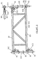
- FIG. 1 Shown in figure 1 is a horizontal scaffold truss member 1, described for background information.
- the truss member 1 has two parallel horizontal pipes, and upper pipe 10 and lower pipe 20, and support elements or bracing members 30 positioned between the two horizontal pipes.
- end connectors 90A, 90B, 90C and 90D (90A and 90C forming upper connectors on upper horizontal 10, and 90B and 9D forming lower connectors on lower horizontal 20).
- the end connectors 90 shown are similar to those shown in U.S. patent number 5,961,240 , but the invention is not so limited.
- the "vertical" separation between the two horizontal pipes 10 and 20 is such so each end connector will mate with a corresponding annular member or connector 80 (here a rosette) on the vertical member 100, as shown in figure 1 .
- upper end connector 90A is pivotally coupled to the end of the upper horizontal pipe 10.
- upper end connector 90A allows the upper horizontal pipe 10 to pivot in a vertical plane with respect to the end connector 90A, about pivot pin 60, allowing the truss member 1, when connector 90A is coupled to the corresponding vertical, to swing in a vertical plane, much like a drawbridge (as used, "vertical” is in a plane that passes through and substantially parallels the vertical scaffold member to which the truss is to be joined or the plane that passes though the parallel upper and lower members of the truss, while "horizontal" pivot implies pivoting in a plane substantially perpendicular to that plane containing the upper and lower members).
- vertical pivoting implies that the truss members distant end pivots toward or away from the ground, pivoting much like a vertically pivoting railroad crossing guard (e.g. a drawbridge type of action), while horizontal pivoting implies that the truss member swings outwardly from the vertical to which it is attached (much like a swinging hinged gate) without substantially changing its height (e.g. pivoting in a plane parallel to the ground).
- the horizontal connector body 90A (not shown in figure 5 ) is generally fixedly mounted on a U shaped connector body 300 having ears 301, shown in figure 5 .
- the connector body 300 then pivots with respect to the horizontal pipe 10 (the horizontal member is positioned interior or between the extending ears 301), by pivoting about a first pivot pin mounted though ears 301 and horizontal upper pipe 10.
- a second pin may be inserted through the pipe 10 and ears to lock the connector in a non-pivoting configuration about the horizontal pipe 10.
- Other means of allowing the connector to pivot with respect to the pipe could be used, as well as other locking means.
- the connector may be mounted to the exterior (or interior) of the pipe using a bearing.
- the connector body 300 may have a lower ear (not shown) used as a stop which would prevent the pipe from vertically pivoting past the projecting ear.
- the selected horizontal system horizontal end connect (not shown in figure 5 ) is mounted to (or integral with) the connector body 300.
- This truss member 1 will be used to form one side of the extended offset platform as follows. A worker, working from the existing scaffold supported platform, such as from a horizontal scaffold deck, will tie a rope to the truss, and suspend the truss upright from the established scaffold structure, or from an overhead structure (such as a bridge member), where the suspended truss upper horizontal 10 is positioned adjacent to the vertical scaffold member to which it is to be coupled, with the couple 90A positioned adjacent to the corresponding joint on the vertical member (here a rosette). The truss member 1 will generally be supported or suspend "above" the corresponding couple rosette point on the vertical that will couple with joint 90A on the suspended truss.
- the worker will then adjust the rope until the pivoting end of couple 90A on the top horizontal scaffold member 10 is directly adjacent to and insertable into the proper rosette.
- a second worker will then couple the horizontal connector 90A to the vertical connector (e.g. position the mouth of the horizontal connector body over the rosette by pivoting connector body 300 so that it is at substantially a right angle to the suspended upright horizontal member 10) and then lock the connector in place (drive in the pin through the connector and rosette opening).
- the first worker then lowers the rope, which results in the downward pivoting of the truss member about the coupled and locked joint 90A, in a vertical plane, until the lower connector body 90B is adjacent to the corresponding rosette on the vertical member.
- the second worker then connects connector 90B with the proper rosette and locks the connector in place.
- One of the workers may slide the locking pin into the aligned opening in the ears of the connector body 300 as a safety measure (not required) to resist further rotation of the truss.
- each end has downwardly extending U shaped connector bodies 300 to couple the plank to the respective horizontal (where the horizontal is a circular pipe member).
- the horizontal is a circular pipe member.
- a worker will then move out on the new deck or platform, carrying a vertical scaffold member. The worker will then attach the vertical to the connectors 90C and 90D, and support the attached vertical to the overhead structure.
- the overhead structure will have a component (such as a first beam) in a vertical plane that passes close to the vertical member to be suspended or the center of the resulting suspended platform (if the beam is substantially off "alignment" with the vertical to be supported, directly supporting the vertical to such a non-aligned overhead beam will not only provide an upward supporting force, but will also provide a horizontal force component, and a large horizontal force component is not preferred).
- a chain can be attached (such as looped around the overhead structure) to the overhead structure and tied to an eyebolt fixed or formed at the top of the vertical. A come-along can be used to shorten (or lengthen) the chain to position the truss member in a level position.
- a second vertical is coupled to the other truss member connectors 90Cand 90D, and similarly supported by or suspended from the overhead structure (again, preferably, the overhead structure includes a second component, such as a beam, in a vertical that passes through or close to the center of the extended platform) and then modify the chain length to level the truss. thereby leveling the resulting platform.
- the overhead structure includes a second component, such as a beam, in a vertical that passes through or close to the center of the extended platform
- Horizontals can then be positioned between the two suspended verticals at the rosettes between corresponding 90D joins and 90C joins, to form a three sided suspended frame for the deck or offset working surface.
- the fourth side of the frame is formed by the ground supported prior existing scaffold frame structure.
- a single horizontal member may be used to join the two suspended verticals, such as at the level of the upper pipes 10, or the lower pipes 20, or two horizontal members used, one between the upper members, and one between the lower members of the opposing trusses. Additional horizontals may be joined between the suspended verticals, and between the suspended verticals and verticals of the existing scaffold structure, as needed, at a height above the installed deck for a safety rail.
- the truss When the truss is initially installed and supported only on one end to a single vertical, the truss is supported on that vertical at two spaced apart locations - the upper joint 90A connection and the lower joint 90B connection to the vertical. This double connection creates a strong, stable joint. Additionally, because the truss itself forms a rigid structure, the single extended truss is more stable than a single extended horizontal. Although the truss member is heavier than a single horizontal, the pivoting joint allows the worker to install the truss vertically, reducing the torque forces that would be present in attempting to tie in the truss, or even a single horizontal at ninety degrees to a vertical (as the truss is supported as it is pivoted downward).
- a grab bar or handle may be included on the truss member to assist in operator manipulation of the truss during installation.
- a pivoting joint on a truss member has been described, a pivoting connector may also be on a single horizontal scaffold member, as opposed to a truss member. While installation is eased with a pivoting horizontal joint, the single horizontal is not as rigid as a truss, and hence is not preferred, but is within the scope of the disclosure.
- the pivoting joint connector is located on the top horizontal of the truss member.
- the pivoting joint member may be positioned on the bottom horizontal (e.g. joint 90B), but this is not preferred.
- the vertically supported upright truss is positioned so the top of the upright truss is positioned adjacent the lower connector on the vertical, with the lower horizontal 20 immediately adjacent the vertical scaffold member.
- the vertically suspended truss 1 is generally suspended below the rosette or annular member that will couple with joint 90B, and hence the suspended truss, once the couple with 90B is established, must now be rotated or pivoted "upwardly” to allow the connector 90A on the top horizontal 10 to come into alignment with the upper connector on the vertical member (as opposed to “lowering” the vertically suspended truss from a pivoting connector on the top horizontal) This raising movement is considered more arduous, and hence, the pivoting bottom connector 90B is not preferred.
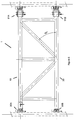
- a second vertically pivoting truss is shown for background information in figure 2 , however, shown in this truss member is a pivoting join on the horizontal that is of the cup/latch type of join. As shown in figure 2 , the truss contains only three connectors, pivoting connector 91A, and non-pivoting connectors 91C and 91 D. Shown attached to the lower truss member at location 91 B is an arcuate shaped body 95, a couple member, shaped to mimic the outer curvature or shape of the vertical scaffold pipe.
- “Arcuate” will be used to indicate that couple member's shape is comparable to that of the vertical for support by that vertical (for instance, if the vertical is square, “arcuate” indicates the couple member is shaped to rest on the vertical - i.e. forms three sides of a square).
- a connecter positioned on the lower truss member cannot properly engage the cup 81 by pivoting into place, as the front of the hook type connector, in a pivot action, would contact the exterior surface of the cup 81.
- the couple member is designed to engage and support the truss against the vertical scaffold member without using a connector to connect to a cup.
- the couple member 95 is preferably shaped to rest on a vertical member and help support the truss member.
- Couple member could also be a clamp positioned around the vertical and joined to the lower horizontal, such as a pivoting clamp.
- Couple member may also be two parallel opposing plates so that when the truss is installed, the vertical member is trapped between the two parallel plates (not shown).
- both ends of the lower horizontal could terminate in a couple member, such as an arcuate shaped coupled member, a clamp, etc.
- a horizontally pivoting embodiment may be used (as later described), or the bottom connector at position 91 B should be slidable vertically with respect to the horizontal member 20, so that the lower connecter 91 B can be moved vertically upwardly, to clear the cup, then downwardly to engage the cup; alternatively, in some connector arrangements, instead of sliding vertically, the second end connector on lower horizontal may be rotatable about an axis aligned with the center of the horizontal member, thereby allowing the second end connector to be positioned adjacent the corresponding cup or rosette or other connector on the vertical, and rotated into proper coupling orientation (not shown).
- the horizontal position of such a rotatable or vertically slidable horizontal end connector preferably is lockable, such as with a pin, to prevent unwanted movement after engagement with the respective cup or rosette.
- the truss member 1 is used to assemble an extended, vertically supported platform as the previous connector. Once one suspended offset platform is in place, this offset platform may now be used as the "fixed" scaffold, and another extended offset platform may now be attached, using a similar construction technique. For instance, if a 9.1 x3 metre (30x10 foot) extended platform is needed, the first 3 metre (ten foot) extended offset platform is erected as an outwardly extending platform from the fixed scaffold structure to create a 3x3 metre (10x10 foot) offset platform.
- a second offset 3 metre (ten foot) platform is built connected to the first offset platform at overhead supported end, thereby creating a 3x9.1 metre (10x30 foot) vertically supported offset platform, and so on (the suspended platform may also be 6x6 metre (20x20), having three parallel trusses each 3 metre (10 feet) across, etc.). Breakdown or disassembly of the platform is performed in substantially the reverse order as assembly.
- a pivoting truss member according to the invention is shown in figure 3 .
- Shown here is a truss member 1 having pivoting connectors 90AH and 90BH. These connectors are designed to pivot in the horizontal plane (like a swinging fence gate), where "horizontal plane” is a plane ninety degrees to the orientation of a vertical member (e.g. parallel to the ground).
- horizontal plane is a plane ninety degrees to the orientation of a vertical member (e.g. parallel to the ground).
- the preferred construction is to have the horizontal members 10 and 20 attached to a U shaped connector body 300, and the connector body 300 pivots with respect to the horizontal members 10 and 20.
- the ears 301 of the connector body 300 are positioned on “top” and “bottom” of the horizontal members s 10 and 20 to provide for horizontal pivoting (whereas the vertically pivoting truss has the ears mounted on the "sides" of the horizontal members).
- the truss is installed in its natural orientation, horizontally.
- the truss should be horizontal but not extending outwardly from the scaffold frame. Instead, the truss should be oriented so that it is adjacent the side of the scaffold platform. In this orientation, a worker can support the truss with almost no torque forces, if supported from the center of the truss (overhead support is not necessary).
- one worker supports the truss and connectors 90AH and 90BH are pivoted to face the respective annular members 80 for engagement and mounting.
- the second horizontally pivoting truss is similarly installed on an adjacent vertical.
- the installed trusses are rotated horizontally (swung outwardly) until they extend outwardly and generally are perpendicular to the scaffold frame.
- decking is laid, verticals are attached to the remote ends of the truss, and the verticals supported from an overhead structure.
- a similar horizontally pivoting truss in a cup/latch embodiment of the invention is shown in figure 4 .
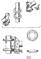
- FIG. 6 Another horizontally pivoting truss embodiment of the invention is shown in figure 6 , using end connectors similar to that shown in U.S. patent number 4,445,307 .
- the latch or lock member does not pivot with respect to the end connector, but is slidable with respect to the end connector (such as a wedge 102 that is slid into position underneath the respective cup in an assembled scaffold joint).
- the two horizontal members 10, and 20 each have horizontally pivoting end connectors 91A and 91 B. Pivoting end connectors are not required on the other end of the truss member. This truss is installed similarly to the truss described in Figure 3 .
- This end connector type may also be used in a vertically pivoting truss arrangement, but as with the vertically pivoting truss cup/latch system shown in figure 2 , the bottom end of the truss adjacent the top pivoting member preferably will not terminate in an end connector, but instead, with a couple member (such as an arcuate shaped member if the vertical is a circular pipe) that will bear against the vertical scaffold member.
- a couple member such as an arcuate shaped member if the vertical is a circular pipe
- the arcuate shaped member 191 may be a half cylinder, with an inner radius equal to that of the outer radius of a vertical scaffold pipe 100, or the couple member could be a clamp, or some combination.
- the end of the lower horizontal member 20 also has a lower cutout 105 to accommodate the adjacent cup 81 on the vertical scaffold member 100 (see, for instance, figure 2 detail).
- a clamp may be used to secure the arcuate shaped member to the vertical scaffold member, such as a pivoting "U" bolt clamp pivotally attached to the horizontal lower member 20 or the arcuate shaped end.
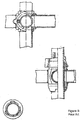
- FIG. 7 Another exemplary pivoting end connector truss is shown in figure 7 , using end connectors similar to those in U.S. patent number 3,992,118 .
- the pivoting end connectors 91A and 92B are horizontally pivoting end connectors - the end connector on the horizontal is basically a pivoting short piece of pipe terminating with an upwardly extending tongue member 301 and downwardly extending tongue member 302.
- the upper 91A and lower 91 B pivoting end connectors at one end of the truss are placed in the annular channels of the corresponding upstanding cups 81 or annular member on a vertical 100 (e.g.
- the downward extending tongues 302 are positioned in the annular channel formed by the upstanding cups 81) and then locked into place (here by sliding the reverse cup 305 on the vertical downward, with the slot in the reverse cup 305 aligned with lug 700 on the vertical member.
- the reverse cup 305 is slid sufficiently far down the vertical to extend past the lug 700, after which the reverse cup 305 is rotated to misalign the slot on the end connector with the lug 700 on the vertical member 100, thereby capturing the upstanding tongue 301 on the pivoting end connector in the annual ring of the reverse cup 305.
- the truss is then swung or pivoted outwardly like a swing gate into the proper orientation with the scaffold frame.
- This end connector type may also be used in a vertically pivoting arrangement, but as with the vertically pivoting truss cup/latch system shown in figure 2 , the bottom end of the truss adjacent the top pivoting member preferably will not terminate in a pivoting end connector.
- the horizontal end connector tongues may have suitable curvature to form the preferred arcuately couple member, suitably adapted (e.g. the downward facing tongue may not be present on this couple member to avoid interference with the corresponding cup on the vertical).
- a clamp or similar attachment can be positioned on the bottom end connector, which would then be clamped to the vertical scaffold member after the truss has been vertically swung into position, when the clamp would be adjacent to the vertical scaffold member.
- the pivoting truss system can be used with most connector types, including traditional tube and clamp scaffolding.
- Scaffold pipes may be round or other shape.
- Each connector is configured to "connect" with an annular member on a vertical scaffold member - that is, when the connector engages the annular member, the join supports the truss (the truss may rotate, for instance, but the truss is nevertheless supported by the engagement or connection).
- the connection may automatically "lock" the vertical to the horizontal (such as in the Excel type spring loaded latch type connectors), or may require action on the part of the operator to lock the horizontal to the vertical (such as in the cup-lock type of connectors, the Safway type of connectors, or the pin-lock type of connectors).
- truss member 1 has connectors 90A, 90B, 91A and 91B that are pin lock type connectors.
- Connector 91 A is mounted to the upper member 10 and is mounted to allow the truss member 1 to pivot vertically.
- Connector 90B is fixedly attached to lower member 20 on the same truss end as connector 90A, and does not pivot.
- the opposite end of truss member 1 has connectors 91A and 91 B attached to the upper and lower members respectively, and are configured to allow the truss member to pivot in the horizontal plane.
- This "dual" pivoting truss allows a single truss member to be used at the user's discretion for vertical or horizontal pivoting, thus eliminating the need to keep separate inventory of two different types of truss members.
- the “dual" pivoting truss can be used with end connectors other than pin lock type, as described previously.
- the jaws of the opening on the truss member fixed connector may be widened to assist installation (see figure 1 , where the upper 1000A and lower jaw 1000B are not parallel, but the upper jaw 1000A is set at an angle (here 28 degrees).
- the truss member connectors described as being fixedly attached to the upper or lower pipe may also be pivotally attached.
- the pivoting truss member is used to erect an overhead supported offset scaffold deck.
- the pivoting truss member is not limited to that application, as there may be applications where the stiffness and extra support of a truss member is needed in a non-overhead supported scaffold structure, and the pivoting truss allows for ease of installation in such applications.
Claims (9)
- Horizontaler Gerüstträger, der ein oberes horizontales Element (10) und ein unteres horizontales Element (20) umfasst, die voneinander getrennt, aber mit mindestens einem Aussteifungselement (30) fest zusammengefügt sind und einen Trägerrahmen bilden, wobei jedes horizontale Element jeweils ein erstes und ein zweites Ende aufweist;
zwei erste Verbinder (90C, 90D, 91C, 91D), die dazu ausgelegt sind, an einem Ringelement (80, 81), das an einem vertikalen Gerüstrohrelement (100) fest positioniert ist und sich davon nach außen erstreckt, entfernbar mit dem vertikalen Gerüstrohrelement (100) verbunden zu sein, wobei an jedem ersten Ende jedes des oberen und des unteren horizontalen Elements einer der zwei ersten Verbinder befestigt ist;
zwei zweite Verbinder (90AH, 90BH, 91 AH, 91BH, 91A, 91B), von denen jeder dazu ausgelegt ist, an einem Ringelement (80, 81), das an einem weiteren vertikalen Gerüstelement (100) fest positioniert ist und sich vom weiteren vertikalen Gerüstrohrelement nach außen erstreckt, entfernbar mit dem weiteren vertikalen Gerüstrohrelement (100) verbunden zu sein, wobei an jedem zweiten Ende jedes des oberen (10) und des unteren (20) horizontalen Elements einer der zwei zweiten Verbinder (90AH, 90BH, 91AH, 91BH, 91A, 91B) schwenkbar befestigt ist, wobei jeder zweite Verbinder mit Bezug auf den Trägerrahmen in einer horizontalen Ebene schwenkbar ist;
wobei jeder der zweiten Verbinder und der ersten Verbinder ein bewegbares Verriegelungselement (102) aufweist, das sich zwischen einer verriegelten Position und einer entriegelten Position bewegt, wobei in der verriegelten Position, wenn der jeweilige zweite Verbinder (90AH, 90BH, 91AH, 91BH, 91A, 91B) oder der jeweilige erste Verbinder (90C, 90D, 91C, 91D) an ein Ringelement (80, 81) an einem vertikalen Gerüstrohrelement (100) gekoppelt ist, das Verriegelungselement (102) der Entkopplung des jeweiligen gekoppelten zweiten Verbinders (90AH, 90BH, 91AH, 91BH, 91A, 91B) oder des jeweiligen gekoppelten ersten Verbinders (90C, 90D, 91C, 91D) aus dem Ringelement (80, 81) widersteht, der gekoppelte zweite Verbinder (90AH, 90BH, 91AH, 91BH, 91A, 91B) mit Bezug auf den Trägerrahmen aber schwenkbar bleibt;
und wobei jedes vertikale Gerüstelement (100) ein vertikales Element mit einer Reihe von vertikal beabstandeten Ringelementen (80, 81) umfasst, die am vertikalen Element positioniert sind, wobei sich jedes Ringelement vom vertikalen Element nach außen erstreckt. - Horizontaler Gerüstträger nach Anspruch 1, wobei (i) einer der ersten Verbinder (90C, 90D, 91C, 91D) am ersten Ende des oberen (10) oder unteren (20) horizontalen Elements nicht schwenkbar fest verbunden ist und der andere der ersten Verbinder am ersten Ende des anderen des oberen oder unteren Elements schwenkbar befestigt ist oder (ii) jeder der ersten Verbinder (90C, 90D, 91C, 91D) an einem der ersten Enden des oberen (10) und des unteren (20) horizontalen Elements nicht schwenkbar fest befestigt ist.
- Horizontaler Gerüstträger nach Anspruch 1, wobei einer der ersten Verbinder (90C, 90D, 91C, 91D) am ersten Ende des oberen (10) oder unteren (20) horizontalen Elements schwenkbar befestigt ist und wobei der schwenkbar befestigte erste Verbinder (90C, 90D, 91C, 91D) dazu ausgelegt ist, den horizontalen Gerüstträger in einer vertikalen Ebene zu schwenken, wenn der horizontale Gerüstträger an einem vertikalen Gerüstelement (100) am schwenkbar befestigten ersten Verbinder an ein Ringelement (80, 81) gekoppelt ist.
- Horizontaler Gerüstträger nach Anspruch 1, wobei die Verriegelungselemente (102) entweder gleitbar oder schwenkbar sind.
- Horizontaler Gerüstträger nach Anspruch 1 oder 3, wobei die zweiten Verbinder (90AH, 90BH, 91AH, 91BH, 91A, 91B) dazu ausgelegt sind, an einem Ringelement (80, 81), das eine Rosette (80) umfasst, die eine Öffnung (22) aufweist, und wobei das Verriegelungselement in der Rosettenöffnung gleitbar ist, entfernbar mit dem weiteren vertikalen Gerüstrohrelement (100) verbunden zu sein.
- Verfahren des Montierens einer hängenden Gerüstplattform an einer bestehenden Gerüststruktur, die vertikale Gerüstelemente aufweist, folgende Schritte umfassend:Bereitstellen eines ersten und eines zweiten horizontalen Gerüstträgerelements, von denen jedes ein oberes horizontales Element (10) und ein unteres horizontales Element (20) umfasst, die voneinander getrennt, aber mit mindestens einem Aussteifungselement (30) fest zusammengefügt sind und jeweils einen ersten und einen zweiten Trägerrahmen bilden, wobei jedes horizontale Element (10, 20) jedes horizontalen Gerüstträgerelements jeweils ein erstes und ein zweites Ende aufweist; dadurch gekennzeichnet, dass:jedes horizontale Gerüstträgerelement ferner Folgendes aufweist:zwei erste Verbinder (90C, 90D, 91C, 91D), die dazu ausgelegt sind, an einem Ringelement (80, 81), das an einem vertikalen Gerüstrohrelement (100) fest positioniert ist und sich davon nach außen erstreckt, entfernbar mit dem vertikalen Gerüstrohrelement (100) verbunden zu sein, wobei an jedem ersten Ende jedes des unteren (20) und des oberen (10) horizontalen Elements des ersten und des zweiten horizontalen Gerüstträgerelements einer der ersten Verbinder (90C, 90D, 91C, 91D) befestigt ist;zwei zweite Verbinder (90AH, 90BH, 91AH, 91BH, 91A, 91B), von denen jeder dazu ausgelegt ist, an einem Ringelement (80, 81), das an einem vertikalen Gerüstelement (100) fest positioniert ist und sich davon nach außen erstreckt, entfernbar mit dem weiteren vertikalen Gerüstrohrelement (100) verbunden zu sein, wobei an jedem zweiten Ende jedes des oberen (10) und des unteren (20) horizontalen Elements einer der zwei zweiten Verbinder (90AH, 90BH, 91AH, 91BH, 91A, 91B) schwenkbar befestigt ist, wobei jeder der zweiten Verbinder mit Bezug auf den zugehörigen Trägerrahmen in einer horizontalen Ebene schwenkbar ist;wobei jeder der zweiten Verbinder und der ersten Verbinder ein bewegbares Verriegelungselement (102) aufweist, das sich zwischen einer verriegeleten Position und einer entriegelten Position bewegt, wobei in der verriegelten Position, wenn der jeweilige zweite Verbinder (90AH, 90BH, 91AH, 91BH, 91A, 91B) oder der jeweilige erste Verbinder (90C, 90D, 91C, 91D) an ein Ringelement (80, 81) an einem vertikalen Gerüstrohrelement (100) gekoppelt ist, das Verriegelungselement (102) der Entkopplung des jeweiligen gekoppelten zweiten Verbinders (90AH, 90BH, 91AH, 91BH, 91A, 91B) oder des jeweiligen gekoppelten ersten Verbinders (90C, 90D, 91C, 91D) aus dem Ringelement (80, 81) widersteht, der gekoppelte zweite Verbinder (90AH, 90BH, 91AH, 91BH, 91A, 91B) mit Bezug auf den Trägerrahmen aber schwenkbar bleibt;wobei das Verfahren ferner die Schritte des Koppelns des ersten horizontalen Gerüstträgerelements an zwei Ringelemente (80, 81) an einem ersten vertikalen Gerüstrohrelement (100) der bestehenden Gerüststruktur umfasst, wobei jedes der zwei Ringelemente (80, 81) an einen der zweiten Verbinder (90AH, 90BH, 91AH, 91BH, 91A, 91B) gekoppelt ist, wobei sich jedes Ringelement (80, 81) vom vertikalen Gerüstrohrelement (100) nach außen erstreckt;des Bewegens jedes der Verriegelungselemente (102) an den zweiten Verbindern des ersten horizontalen Gerüstträgerelements in eine verriegelte Position;des Schwenkens des ersten horizontalen Gerüstträgerelements um die zweiten Verbinder (90AH, 90BH, 91AH, 91BH, 91A, 91B) am ersten horizontalen Gerüstträgerelement, um die ersten Enden der horizontalen Elemente des ersten horizontalen Gerüstträgerelements aus einer Lage proximal zur bestehenden Gerüststruktur in eine gewünschte Ausrichtung distal zur bestehenden Gerüststruktur zu bewegen;des Koppelns des zweiten horizontalen Gerüstträgerelements an zwei Ringelemente (80, 81, 16) an einem zweiten vertikalen Gerüstrohrelement (100) der bestehenden Gerüststruktur, wobei jedes der zwei Ringelemente (80, 81) an einen der zweiten Verbinder (90AH, 90BH, 91AH, 91BH, 91A) des zweiten horizontalen Gerüstträgerelements gekoppelt ist, wobei sich die Ringelemente (80, 81) am zweiten vertikalen Gerüstrohrelement (100) vom zweiten vertikalen Gerüstrohrelement nach außen erstrecken;des Bewegens der Verriegelungselemente (102) an den zweiten Verbindern am zweiten horizontalen Gerüstträgerelement in eine verriegelte Position;des Schwenkens des zweiten horizontalen Gerüstträgerelements horizontal um die zweiten Verbinder (90AH, 90BH, 91AH, 91BH, 91A, 91B) am zweiten horizontalen Gerüstträgerelement, um die ersten Enden der horizontalen Elemente des zweiten horizontalen Gerüstträgerelements aus einer Lage proximal zur bestehenden Gerüststruktur in eine gewünschte Ausrichtung distal zur bestehenden Gerüststruktur zu bewegen;des Platzierens von Gerüstbeplankungsbrettern, um zwischen dem geschwenkten ersten und zweiten horizontalen Gerüstträgerelement eine Arbeitsfläche zu erstellen;des Koppelns eines dritten vertikalen Gerüstrohrelements (100) an die ersten Verbinder des ersten horizontalen Gerüstträgerelements;des Koppelns eines vierten vertikalen Gerüstrohrelements (100) an die ersten Verbinder des zweiten horizontalen Gerüstträgerelements;des Stützens des dritten vertikalen Gerüstelements von einer Überkopfstruktur unddes Stützens des vierten vertikalen Gerüstelements von einer Überkopfstruktur.
- Verfahren nach Anspruch 6, wobei an einem oder an beiden der ersten Enden der horizontalen Elemente jedes des ersten horizontalen Gerüstträgerelements und des zweiten horizontalen Gerüstträgerelements jeweils einer von den zwei ersten Verbindern nicht schwenkbar fest befestigt ist.
- Verfahren nach Anspruch 6, wobei der Schritt des Schwenkens des ersten horizontalen Gerüstträgerelements vom Schritt des Schwenkens des zweiten horizontalen Gerüstträgerelements unabhängig ist
- Verfahren nach Anspruch 6, wobei einer der ersten Verbinder am ersten Ende des oberen (10) oder unteren (20) horizontalen Elements jedes des ersten horizontalen Gerüstträgers und des zweiten horizontalen Gerüstträgerelements schwenkbar befestigt ist und wobei der schwenkbar befestigte erste Verbinder dazu ausgelegt ist, den horizontalen Gerüstträger in einer vertikalen Ebene zu schwenken, wenn der horizontale Gerüstträger an einem vertikalen Gerüstelement (100) am schwenkbar befestigten ersten Verbinder an ein Ringelement (80, 81) gekoppelt ist.
Priority Applications (1)
| Application Number | Priority Date | Filing Date | Title |
|---|---|---|---|
| PL12845108T PL2649257T3 (pl) | 2011-11-02 | 2012-10-30 | Obrotowe poziome i pionowe elementy rusztowania i sposób stawiania wysuniętego pomostu rusztowania |
Applications Claiming Priority (3)
| Application Number | Priority Date | Filing Date | Title |
|---|---|---|---|
| US201161628607P | 2011-11-02 | 2011-11-02 | |
| US201261599118P | 2012-02-15 | 2012-02-15 | |
| PCT/US2012/062557 WO2013066859A1 (en) | 2011-11-02 | 2012-10-30 | Pivoting horizontal and vertical scaffold members and a method of erecting an offset scaffold platform |
Publications (3)
| Publication Number | Publication Date |
|---|---|
| EP2649257A1 EP2649257A1 (de) | 2013-10-16 |
| EP2649257A4 EP2649257A4 (de) | 2014-06-18 |
| EP2649257B1 true EP2649257B1 (de) | 2017-08-09 |
Family
ID=48192675
Family Applications (1)
| Application Number | Title | Priority Date | Filing Date |
|---|---|---|---|
| EP12845108.5A Active EP2649257B1 (de) | 2011-11-02 | 2012-10-30 | Schwenkbares horizontales und vertikales gerüstelement und verfahren zur errichtung einer versetzten arbeitsbühne |
Country Status (9)
| Country | Link |
|---|---|
| US (5) | US20140020982A1 (de) |
| EP (1) | EP2649257B1 (de) |
| AU (1) | AU2012332760C1 (de) |
| CA (1) | CA2824872C (de) |
| DK (1) | DK2649257T3 (de) |
| ES (1) | ES2644927T3 (de) |
| MX (1) | MX360841B (de) |
| PL (1) | PL2649257T3 (de) |
| WO (1) | WO2013066859A1 (de) |
Families Citing this family (19)
| Publication number | Priority date | Publication date | Assignee | Title |
|---|---|---|---|---|
| US7779599B2 (en) | 2004-03-31 | 2010-08-24 | Safway Services, Llc | Articulating work platform support system, work platform system, and methods of use thereof |
| DE102012109860A1 (de) * | 2012-10-16 | 2014-04-17 | Max Bögl Wind AG | Versorgungsgerüst für einen Turm,Turm mit einem Versorgungsgerüst sowie Verfahren zum Errichten eines Versorgungsgerüsts im Inneren eines Turms |
| US9476575B2 (en) * | 2013-03-04 | 2016-10-25 | Revolution Display, Llc | Video display module support assembly |
| SE538860C2 (sv) * | 2015-05-21 | 2017-01-10 | Mon Zon Dev Ab | Flexible fastening unit for a beam |
| DE102015213737A1 (de) * | 2015-07-21 | 2017-01-26 | Peri Gmbh | Kupplung und Gerüst mit einer solchen Kupplung |
| DE102015012275A1 (de) * | 2015-09-24 | 2017-03-30 | Wilhelm Layher Verwaltungs-Gmbh | Gitterträger und Gitterträgersystem, insbesondere zum universellen Einsatz innerhalb eines bekannten Arbeits- und Schutzgerüsts |
| US11624196B2 (en) | 2016-06-24 | 2023-04-11 | Apache Industrial Services, Inc | Connector end fitting for an integrated construction system |
| US10472823B2 (en) | 2016-06-24 | 2019-11-12 | Apache Industrial Services, Inc. | Formwork system |
| US10415262B2 (en) * | 2016-06-24 | 2019-09-17 | Apache Industrial Services, Inc. | Modular ledgers of an integrated construction system |
| US11306492B2 (en) | 2016-06-24 | 2022-04-19 | Apache Industrial Services, Inc | Load bearing components and safety deck of an integrated construction system |
| US10465399B2 (en) | 2016-06-24 | 2019-11-05 | Apache Industrial Services, Inc. | Integrated construction system |
| AU2017202444B2 (en) * | 2016-12-19 | 2019-06-20 | Voideck Ipco Limited | A void platform and a method for providing a platform support across a building void |
| WO2018140477A1 (en) * | 2017-01-25 | 2018-08-02 | Bechtel Oil, Gas And Chemicals, Inc. | Scaffolding system for use with curvilinear walls and method of use |
| NL2018515B1 (nl) * | 2017-03-15 | 2018-09-24 | Scafom Holding B V | Zwenkligger en steigersysteem met een dergelijk zwenkligger en een werkwijze voor het opbouwen van het steigersysteem. |
| US11332947B2 (en) * | 2017-03-23 | 2022-05-17 | Deltak Manufacturing, Inc. | Intermediate scaffold joint |
| US20190017282A1 (en) * | 2017-07-14 | 2019-01-17 | Dhs Fraco Ltee | Runback backstructure access system |
| DE102017216255A1 (de) * | 2017-09-14 | 2019-03-14 | Peri Gmbh | Gerüstriegel, Gerüst und Verfahren zum Aufbau eines Gerüsts |
| US11268288B2 (en) * | 2018-04-10 | 2022-03-08 | Deltak Manufacturing, Inc. | Triple latching horizontal scaffold member with three triggers |
| CN115613798B (zh) * | 2022-10-27 | 2023-10-03 | 北京房地集团有限公司 | 一种悬挑脚手架悬挑梁的安装结构及安装方法 |
Citations (3)
| Publication number | Priority date | Publication date | Assignee | Title |
|---|---|---|---|---|
| EP0623716A1 (de) * | 1993-05-04 | 1994-11-09 | Ulma, S.Coop. Ltda. | Verbessertes räumliches Gerüst |
| DE19637543A1 (de) * | 1996-09-14 | 1998-03-26 | Simon Gmbh & Co Kg Geruest Und | Traggestell für ein Arbeitsgerüst |
| DE19703558A1 (de) * | 1997-01-31 | 1998-08-06 | Georg Layher | Stabeinrichtung für ein Gerüstsystem |
Family Cites Families (45)
| Publication number | Priority date | Publication date | Assignee | Title |
|---|---|---|---|---|
| US3179212A (en) * | 1962-01-30 | 1965-04-20 | Kwikform Ltd | Builders' scaffolding |
| NL175840B (nl) | 1973-10-10 | 1984-08-01 | Sgb Group Plc | Verbindingsconstructie voor toepassing in een buisvormige steiger of stelling. |
| GB1507029A (en) * | 1974-07-19 | 1978-04-12 | Kwikform Ltd | Scaffolding constructions |
| DE2704398C3 (de) * | 1977-02-03 | 1980-08-21 | Plettac Gmbh, 5970 Plettenberg | Aus Ständern und Riegeln zusammensetzbares Gerüst |
| US4273463A (en) | 1979-10-03 | 1981-06-16 | Gerhard Dobersch | Steel tube scaffold |
| GB2066341B (en) * | 1979-12-21 | 1983-06-02 | Press Components Co Ltd | Scaffolding brace |
| ATE6801T1 (de) | 1980-01-15 | 1984-04-15 | Sgb Group Public Limited Company | Geruestsystem. |
| FR2522708A1 (fr) * | 1982-03-03 | 1983-09-09 | Comabi | Perfectionnement aux echafaudages |
| US4445307A (en) | 1982-11-08 | 1984-05-01 | Figgie International Inc. | Scaffold joint for a scaffold structure |
| US4525096A (en) * | 1983-04-18 | 1985-06-25 | Weldtec, Inc. | Connecting clamp for builder's scaffolding |
| US4624374A (en) * | 1984-09-20 | 1986-11-25 | Med Marine International Inc. | Universal connector |
| US4840513A (en) | 1986-11-05 | 1989-06-20 | Hackett Steven B | Scaffolding connector apparatus |
| DE3702057A1 (de) * | 1987-01-24 | 1988-08-04 | Langer Ruth Geb Layher | Geruest mit verbindungsvorrichtungen |
| FR2660708B1 (fr) * | 1990-04-04 | 1993-05-21 | Perruelle Claude | Piece d'assemblage pour elements longiformes. |
| US5028164A (en) | 1990-09-13 | 1991-07-02 | Williams Joe W | Scaffold connection |
| US5078532A (en) | 1990-09-13 | 1992-01-07 | Williams Joe W | Scaffold connection |
| CA2040341C (en) * | 1991-04-12 | 1999-07-13 | John Brasil | Connecting piece for scaffolding |
| US5207527A (en) * | 1992-04-13 | 1993-05-04 | Warren Duncan | System scaffold wedging arrangement |
| US5351784A (en) * | 1994-03-24 | 1994-10-04 | Sung Te Fu | Protective device for a scaffold |
| US5645271A (en) * | 1994-07-11 | 1997-07-08 | Nunez; Marcos D. | Metal fence post with adjustable rail mounting |
| FR2743103B1 (fr) * | 1995-12-27 | 1998-04-03 | Hussor Erecta Sa | Panneau garde-corps de securite, en particulier pour echafaudage multidirectionnel |
| DE19602737A1 (de) | 1996-01-26 | 1997-07-31 | Peri Gmbh | Gerüstknoten |
| CA2201535C (en) | 1997-04-02 | 2006-09-19 | Aluma Systems Corp. | Scaffolding connector |
| JP4268701B2 (ja) * | 1997-12-26 | 2009-05-27 | 辰雄 小野 | 枠体及び枠体を組付けた構造体 |
| DE69910347D1 (de) * | 1999-03-05 | 2003-09-18 | Hasegawa Kogyo Co | Hakenvorrichtung |
| DE19946929A1 (de) * | 1999-09-30 | 2001-04-05 | Assco Gerueste Gmbh & Co | Vorrichtung zur Verbindung zweier benachbarten Gerüststiele |
| SE519230C2 (sv) | 2000-09-06 | 2003-02-04 | Pluseight Technology Ab | Anordning för sammankoppling av ställningselement |
| US6575652B2 (en) * | 2001-01-16 | 2003-06-10 | Kurt F. Krauss | Structural couplings and system |
| SE521500C2 (sv) * | 2001-03-27 | 2003-11-04 | Pluseight Safety Ab | Anordning för personskydd vid byggnadsställningar och förfarande för att skydda personer medelst sådan anordning |
| DE10115232A1 (de) * | 2001-03-28 | 2002-10-02 | Lung Ching Shih | Stützenverbindungsring |
| DE602004029820D1 (de) * | 2004-03-16 | 2010-12-09 | Ulma C Y E S Coop | Stütze mit versteifungsmitteln |
| US7779599B2 (en) * | 2004-03-31 | 2010-08-24 | Safway Services, Llc | Articulating work platform support system, work platform system, and methods of use thereof |
| CA2535970C (en) * | 2006-02-10 | 2008-08-19 | Porfirio Simoes | Scaffold support bracket and assembly |
| US7971686B1 (en) * | 2007-04-20 | 2011-07-05 | Excel Modular Scaffold And Leasing Corporation | Double latched scaffold connector |
| GB0716658D0 (en) * | 2007-08-25 | 2007-10-03 | Owens Andrew C | Scaffolding stairway system |
| JP2009299307A (ja) * | 2008-06-11 | 2009-12-24 | Taisen Industry Co Ltd | ユニット式足場および連結具 |
| FR2934290B1 (fr) * | 2008-07-23 | 2016-07-29 | Tubesca | Element d'echafaudage pliant, application d'un tel element d'echafaudage pliant et echafaudage comportant un tel element d'echafaudage pliant |
| NL2003206C2 (nl) * | 2009-07-15 | 2011-01-18 | Scafom Internat B V | Steigersysteem, alsmede koppeling, liggerbuis en staanderbuis bestemd voor een dergelijk steigersysteem. |
| US9482020B2 (en) * | 2009-07-21 | 2016-11-01 | Deltak Manufacturing, Inc. | Method of assembling an offset working platform on a scaffold structure using a foldable knee-out scaffold frame member |
| EP2354375A1 (de) * | 2010-01-14 | 2011-08-10 | Jerslev Stilladsservice A/S | Gerüstsystem |
| US8393439B2 (en) | 2010-01-26 | 2013-03-12 | Steve Howard Thacker | Scaffold system and method |
| US20130126270A1 (en) * | 2011-11-17 | 2013-05-23 | Youngman Group Limited | Advanced guard rail |
| AU2013101084B4 (en) * | 2013-02-11 | 2015-02-05 | 4 Ken Pty Ltd | Method and system for oblique scaffold connection |
| SE538860C2 (sv) * | 2015-05-21 | 2017-01-10 | Mon Zon Dev Ab | Flexible fastening unit for a beam |
| JP2017114373A (ja) * | 2015-12-25 | 2017-06-29 | 矢崎総業株式会社 | ジャンクションボックス |
-
2012
- 2012-10-30 PL PL12845108T patent/PL2649257T3/pl unknown
- 2012-10-30 EP EP12845108.5A patent/EP2649257B1/de active Active
- 2012-10-30 US US13/997,101 patent/US20140020982A1/en not_active Abandoned
- 2012-10-30 MX MX2013011821A patent/MX360841B/es active IP Right Grant
- 2012-10-30 CA CA2824872A patent/CA2824872C/en active Active
- 2012-10-30 AU AU2012332760A patent/AU2012332760C1/en active Active
- 2012-10-30 WO PCT/US2012/062557 patent/WO2013066859A1/en active Application Filing
- 2012-10-30 ES ES12845108.5T patent/ES2644927T3/es active Active
- 2012-10-30 DK DK12845108.5T patent/DK2649257T3/en active
-
2014
- 2014-04-29 US US14/265,074 patent/US20140234014A1/en not_active Abandoned
-
2016
- 2016-02-25 US US15/053,894 patent/US10400460B2/en active Active
-
2019
- 2019-08-01 US US16/529,150 patent/US10995505B2/en active Active
-
2021
- 2021-03-16 US US17/202,824 patent/US20210270048A1/en not_active Abandoned
Patent Citations (3)
| Publication number | Priority date | Publication date | Assignee | Title |
|---|---|---|---|---|
| EP0623716A1 (de) * | 1993-05-04 | 1994-11-09 | Ulma, S.Coop. Ltda. | Verbessertes räumliches Gerüst |
| DE19637543A1 (de) * | 1996-09-14 | 1998-03-26 | Simon Gmbh & Co Kg Geruest Und | Traggestell für ein Arbeitsgerüst |
| DE19703558A1 (de) * | 1997-01-31 | 1998-08-06 | Georg Layher | Stabeinrichtung für ein Gerüstsystem |
Also Published As
| Publication number | Publication date |
|---|---|
| US10995505B2 (en) | 2021-05-04 |
| US20210270048A1 (en) | 2021-09-02 |
| MX360841B (es) | 2018-11-20 |
| US10400460B2 (en) | 2019-09-03 |
| WO2013066859A1 (en) | 2013-05-10 |
| EP2649257A4 (de) | 2014-06-18 |
| US20190390469A1 (en) | 2019-12-26 |
| AU2012332760B2 (en) | 2015-11-26 |
| CA2824872A1 (en) | 2013-05-10 |
| DK2649257T3 (en) | 2017-10-02 |
| MX2013011821A (es) | 2013-12-06 |
| AU2012332760C1 (en) | 2016-05-12 |
| US20140020982A1 (en) | 2014-01-23 |
| ES2644927T3 (es) | 2017-12-01 |
| US20160177581A1 (en) | 2016-06-23 |
| US20140234014A1 (en) | 2014-08-21 |
| PL2649257T3 (pl) | 2017-12-29 |
| CA2824872C (en) | 2016-10-04 |
| EP2649257A1 (de) | 2013-10-16 |
Similar Documents
| Publication | Publication Date | Title |
|---|---|---|
| US10995505B2 (en) | Pivoting horizontal and vertical scaffold members and a method of erecting an offset scaffold platform | |
| AU2012332760A1 (en) | Pivoting horizontal and vertical scaffold members and a method of erecting an offset scaffold platform | |
| US10968644B2 (en) | Kit for erecting a platform | |
| JP6813546B2 (ja) | 吊り下げられたパネル部を含むワークプラットフォームシステム及びワークプラットフォームシステムの実装方法 | |
| US9175487B2 (en) | Self-climbing perimetric protection system for construction works in buildings | |
| US20110132685A1 (en) | Scaffolding | |
| US20130043095A1 (en) | Masonry scaffold system with truss level rosettes | |
| KR100841240B1 (ko) | 건축용 조립식 비계 | |
| US4382488A (en) | Pump jack poles | |
| KR20160011714A (ko) | 현수된 패널형 부분을 포함하는 작업 플랫폼 시스템 및 그 구현 방법 | |
| US9260873B1 (en) | Truss member and truss connector | |
| US6006862A (en) | Temporary guard rail assembly for scaffolding | |
| KR20160045736A (ko) | 액세스 구조 통합 조립체 및 이를 이용한 통합형 액세스 시스템 및 방법 | |
| AU2012200673B2 (en) | Barrier | |
| JP2010196403A (ja) | 先行手摺 | |
| IES20090644A2 (en) | A method and apparatus for erecting a mobile scaffold tower | |
| EP2205808A2 (de) | Sicherheitsstruktur für ein gerüstsystem | |
| IE20100728U1 (en) | A guard rail system | |
| GB2427243A (en) | Scaffold tube coupler including clamp and hook |
Legal Events
| Date | Code | Title | Description |
|---|---|---|---|
| PUAI | Public reference made under article 153(3) epc to a published international application that has entered the european phase |
Free format text: ORIGINAL CODE: 0009012 |
|
| 17P | Request for examination filed |
Effective date: 20130708 |
|
| AK | Designated contracting states |
Kind code of ref document: A1 Designated state(s): AL AT BE BG CH CY CZ DE DK EE ES FI FR GB GR HR HU IE IS IT LI LT LU LV MC MK MT NL NO PL PT RO RS SE SI SK SM TR |
|
| A4 | Supplementary search report drawn up and despatched |
Effective date: 20140519 |
|
| RIC1 | Information provided on ipc code assigned before grant |
Ipc: E04G 1/14 20060101ALI20140513BHEP Ipc: E04G 7/30 20060101ALI20140513BHEP Ipc: E04G 7/32 20060101ALI20140513BHEP Ipc: E04G 1/06 20060101AFI20140513BHEP |
|
| RIN1 | Information on inventor provided before grant (corrected) |
Inventor name: HAYMAN, YATES, W. Inventor name: CURTIS, JOHNNY Inventor name: THACKER, STEPHEN |
|
| DAX | Request for extension of the european patent (deleted) | ||
| 17Q | First examination report despatched |
Effective date: 20150327 |
|
| REG | Reference to a national code |
Ref country code: DE Ref legal event code: R079 Ref document number: 602012035810 Country of ref document: DE Free format text: PREVIOUS MAIN CLASS: E04G0001060000 Ipc: E04G0005000000 |
|
| GRAP | Despatch of communication of intention to grant a patent |
Free format text: ORIGINAL CODE: EPIDOSNIGR1 |
|
| STAA | Information on the status of an ep patent application or granted ep patent |
Free format text: STATUS: GRANT OF PATENT IS INTENDED |
|
| RIC1 | Information provided on ipc code assigned before grant |
Ipc: E04G 1/14 20060101ALI20161103BHEP Ipc: E04G 7/30 20060101ALI20161103BHEP Ipc: E04G 5/00 20060101AFI20161103BHEP Ipc: E04G 7/32 20060101ALI20161103BHEP |
|
| INTG | Intention to grant announced |
Effective date: 20161117 |
|
| GRAJ | Information related to disapproval of communication of intention to grant by the applicant or resumption of examination proceedings by the epo deleted |
Free format text: ORIGINAL CODE: EPIDOSDIGR1 |
|
| STAA | Information on the status of an ep patent application or granted ep patent |
Free format text: STATUS: EXAMINATION IS IN PROGRESS |
|
| GRAP | Despatch of communication of intention to grant a patent |
Free format text: ORIGINAL CODE: EPIDOSNIGR1 |
|
| STAA | Information on the status of an ep patent application or granted ep patent |
Free format text: STATUS: GRANT OF PATENT IS INTENDED |
|
| INTC | Intention to grant announced (deleted) | ||
| INTG | Intention to grant announced |
Effective date: 20170313 |
|
| GRAS | Grant fee paid |
Free format text: ORIGINAL CODE: EPIDOSNIGR3 |
|
| GRAA | (expected) grant |
Free format text: ORIGINAL CODE: 0009210 |
|
| STAA | Information on the status of an ep patent application or granted ep patent |
Free format text: STATUS: THE PATENT HAS BEEN GRANTED |
|
| AK | Designated contracting states |
Kind code of ref document: B1 Designated state(s): AL AT BE BG CH CY CZ DE DK EE ES FI FR GB GR HR HU IE IS IT LI LT LU LV MC MK MT NL NO PL PT RO RS SE SI SK SM TR |
|
| REG | Reference to a national code |
Ref country code: GB Ref legal event code: FG4D |
|
| REG | Reference to a national code |
Ref country code: AT Ref legal event code: REF Ref document number: 917025 Country of ref document: AT Kind code of ref document: T Effective date: 20170815 Ref country code: CH Ref legal event code: EP |
|
| REG | Reference to a national code |
Ref country code: IE Ref legal event code: FG4D |
|
| REG | Reference to a national code |
Ref country code: CH Ref legal event code: NV Representative=s name: VENI GMBH, CH |
|
| REG | Reference to a national code |
Ref country code: DE Ref legal event code: R096 Ref document number: 602012035810 Country of ref document: DE |
|
| REG | Reference to a national code |
Ref country code: DK Ref legal event code: T3 Effective date: 20170929 |
|
| REG | Reference to a national code |
Ref country code: SE Ref legal event code: TRGR |
|
| REG | Reference to a national code |
Ref country code: FR Ref legal event code: PLFP Year of fee payment: 6 |
|
| REG | Reference to a national code |
Ref country code: NL Ref legal event code: FP |
|
| REG | Reference to a national code |
Ref country code: ES Ref legal event code: FG2A Ref document number: 2644927 Country of ref document: ES Kind code of ref document: T3 Effective date: 20171201 |
|
| REG | Reference to a national code |
Ref country code: NO Ref legal event code: T2 Effective date: 20170809 |
|
| REG | Reference to a national code |
Ref country code: LT Ref legal event code: MG4D |
|
| PG25 | Lapsed in a contracting state [announced via postgrant information from national office to epo] |
Ref country code: LT Free format text: LAPSE BECAUSE OF FAILURE TO SUBMIT A TRANSLATION OF THE DESCRIPTION OR TO PAY THE FEE WITHIN THE PRESCRIBED TIME-LIMIT Effective date: 20170809 Ref country code: HR Free format text: LAPSE BECAUSE OF FAILURE TO SUBMIT A TRANSLATION OF THE DESCRIPTION OR TO PAY THE FEE WITHIN THE PRESCRIBED TIME-LIMIT Effective date: 20170809 |
|
| PG25 | Lapsed in a contracting state [announced via postgrant information from national office to epo] |
Ref country code: GR Free format text: LAPSE BECAUSE OF FAILURE TO SUBMIT A TRANSLATION OF THE DESCRIPTION OR TO PAY THE FEE WITHIN THE PRESCRIBED TIME-LIMIT Effective date: 20171110 Ref country code: IS Free format text: LAPSE BECAUSE OF FAILURE TO SUBMIT A TRANSLATION OF THE DESCRIPTION OR TO PAY THE FEE WITHIN THE PRESCRIBED TIME-LIMIT Effective date: 20171209 Ref country code: RS Free format text: LAPSE BECAUSE OF FAILURE TO SUBMIT A TRANSLATION OF THE DESCRIPTION OR TO PAY THE FEE WITHIN THE PRESCRIBED TIME-LIMIT Effective date: 20170809 Ref country code: LV Free format text: LAPSE BECAUSE OF FAILURE TO SUBMIT A TRANSLATION OF THE DESCRIPTION OR TO PAY THE FEE WITHIN THE PRESCRIBED TIME-LIMIT Effective date: 20170809 Ref country code: BG Free format text: LAPSE BECAUSE OF FAILURE TO SUBMIT A TRANSLATION OF THE DESCRIPTION OR TO PAY THE FEE WITHIN THE PRESCRIBED TIME-LIMIT Effective date: 20171109 |
|
| PG25 | Lapsed in a contracting state [announced via postgrant information from national office to epo] |
Ref country code: CZ Free format text: LAPSE BECAUSE OF FAILURE TO SUBMIT A TRANSLATION OF THE DESCRIPTION OR TO PAY THE FEE WITHIN THE PRESCRIBED TIME-LIMIT Effective date: 20170809 Ref country code: RO Free format text: LAPSE BECAUSE OF FAILURE TO SUBMIT A TRANSLATION OF THE DESCRIPTION OR TO PAY THE FEE WITHIN THE PRESCRIBED TIME-LIMIT Effective date: 20170809 |
|
| REG | Reference to a national code |
Ref country code: DE Ref legal event code: R097 Ref document number: 602012035810 Country of ref document: DE |
|
| PG25 | Lapsed in a contracting state [announced via postgrant information from national office to epo] |
Ref country code: SM Free format text: LAPSE BECAUSE OF FAILURE TO SUBMIT A TRANSLATION OF THE DESCRIPTION OR TO PAY THE FEE WITHIN THE PRESCRIBED TIME-LIMIT Effective date: 20170809 Ref country code: SK Free format text: LAPSE BECAUSE OF FAILURE TO SUBMIT A TRANSLATION OF THE DESCRIPTION OR TO PAY THE FEE WITHIN THE PRESCRIBED TIME-LIMIT Effective date: 20170809 Ref country code: EE Free format text: LAPSE BECAUSE OF FAILURE TO SUBMIT A TRANSLATION OF THE DESCRIPTION OR TO PAY THE FEE WITHIN THE PRESCRIBED TIME-LIMIT Effective date: 20170809 Ref country code: MC Free format text: LAPSE BECAUSE OF FAILURE TO SUBMIT A TRANSLATION OF THE DESCRIPTION OR TO PAY THE FEE WITHIN THE PRESCRIBED TIME-LIMIT Effective date: 20170809 |
|
| PLBE | No opposition filed within time limit |
Free format text: ORIGINAL CODE: 0009261 |
|
| STAA | Information on the status of an ep patent application or granted ep patent |
Free format text: STATUS: NO OPPOSITION FILED WITHIN TIME LIMIT |
|
| 26N | No opposition filed |
Effective date: 20180511 |
|
| REG | Reference to a national code |
Ref country code: IE Ref legal event code: MM4A |
|
| PG25 | Lapsed in a contracting state [announced via postgrant information from national office to epo] |
Ref country code: LU Free format text: LAPSE BECAUSE OF NON-PAYMENT OF DUE FEES Effective date: 20171030 |
|
| PG25 | Lapsed in a contracting state [announced via postgrant information from national office to epo] |
Ref country code: SI Free format text: LAPSE BECAUSE OF FAILURE TO SUBMIT A TRANSLATION OF THE DESCRIPTION OR TO PAY THE FEE WITHIN THE PRESCRIBED TIME-LIMIT Effective date: 20170809 |
|
| PG25 | Lapsed in a contracting state [announced via postgrant information from national office to epo] |
Ref country code: MT Free format text: LAPSE BECAUSE OF NON-PAYMENT OF DUE FEES Effective date: 20171030 |
|
| REG | Reference to a national code |
Ref country code: FR Ref legal event code: PLFP Year of fee payment: 7 |
|
| PG25 | Lapsed in a contracting state [announced via postgrant information from national office to epo] |
Ref country code: IE Free format text: LAPSE BECAUSE OF NON-PAYMENT OF DUE FEES Effective date: 20171030 |
|
| PG25 | Lapsed in a contracting state [announced via postgrant information from national office to epo] |
Ref country code: HU Free format text: LAPSE BECAUSE OF FAILURE TO SUBMIT A TRANSLATION OF THE DESCRIPTION OR TO PAY THE FEE WITHIN THE PRESCRIBED TIME-LIMIT; INVALID AB INITIO Effective date: 20121030 |
|
| PG25 | Lapsed in a contracting state [announced via postgrant information from national office to epo] |
Ref country code: CY Free format text: LAPSE BECAUSE OF NON-PAYMENT OF DUE FEES Effective date: 20170809 |
|
| PG25 | Lapsed in a contracting state [announced via postgrant information from national office to epo] |
Ref country code: MK Free format text: LAPSE BECAUSE OF FAILURE TO SUBMIT A TRANSLATION OF THE DESCRIPTION OR TO PAY THE FEE WITHIN THE PRESCRIBED TIME-LIMIT Effective date: 20170809 |
|
| PG25 | Lapsed in a contracting state [announced via postgrant information from national office to epo] |
Ref country code: TR Free format text: LAPSE BECAUSE OF FAILURE TO SUBMIT A TRANSLATION OF THE DESCRIPTION OR TO PAY THE FEE WITHIN THE PRESCRIBED TIME-LIMIT Effective date: 20170809 |
|
| PG25 | Lapsed in a contracting state [announced via postgrant information from national office to epo] |
Ref country code: PT Free format text: LAPSE BECAUSE OF FAILURE TO SUBMIT A TRANSLATION OF THE DESCRIPTION OR TO PAY THE FEE WITHIN THE PRESCRIBED TIME-LIMIT Effective date: 20170809 |
|
| PG25 | Lapsed in a contracting state [announced via postgrant information from national office to epo] |
Ref country code: AL Free format text: LAPSE BECAUSE OF FAILURE TO SUBMIT A TRANSLATION OF THE DESCRIPTION OR TO PAY THE FEE WITHIN THE PRESCRIBED TIME-LIMIT Effective date: 20170809 |
|
| REG | Reference to a national code |
Ref country code: AT Ref legal event code: UEP Ref document number: 917025 Country of ref document: AT Kind code of ref document: T Effective date: 20170809 |
|
| PGFP | Annual fee paid to national office [announced via postgrant information from national office to epo] |
Ref country code: PL Payment date: 20221017 Year of fee payment: 11 Ref country code: BE Payment date: 20221019 Year of fee payment: 11 |
|
| PGFP | Annual fee paid to national office [announced via postgrant information from national office to epo] |
Ref country code: NL Payment date: 20231016 Year of fee payment: 12 |
|
| PGFP | Annual fee paid to national office [announced via postgrant information from national office to epo] |
Ref country code: GB Payment date: 20231006 Year of fee payment: 12 |
|
| PGFP | Annual fee paid to national office [announced via postgrant information from national office to epo] |
Ref country code: ES Payment date: 20231103 Year of fee payment: 12 |
|
| PGFP | Annual fee paid to national office [announced via postgrant information from national office to epo] |
Ref country code: SE Payment date: 20231010 Year of fee payment: 12 Ref country code: NO Payment date: 20231010 Year of fee payment: 12 Ref country code: IT Payment date: 20231010 Year of fee payment: 12 Ref country code: FR Payment date: 20231009 Year of fee payment: 12 Ref country code: FI Payment date: 20231011 Year of fee payment: 12 Ref country code: DK Payment date: 20231016 Year of fee payment: 12 Ref country code: DE Payment date: 20231010 Year of fee payment: 12 Ref country code: CH Payment date: 20231102 Year of fee payment: 12 Ref country code: AT Payment date: 20231009 Year of fee payment: 12 |
|
| PGFP | Annual fee paid to national office [announced via postgrant information from national office to epo] |
Ref country code: PL Payment date: 20231006 Year of fee payment: 12 Ref country code: BE Payment date: 20231016 Year of fee payment: 12 |