EP2645945B1 - Vorrichtung zur entnahme eines körpers aus einer rohrförmigen struktur - Google Patents
Vorrichtung zur entnahme eines körpers aus einer rohrförmigen struktur Download PDFInfo
- Publication number
- EP2645945B1 EP2645945B1 EP11845817.3A EP11845817A EP2645945B1 EP 2645945 B1 EP2645945 B1 EP 2645945B1 EP 11845817 A EP11845817 A EP 11845817A EP 2645945 B1 EP2645945 B1 EP 2645945B1
- Authority
- EP
- European Patent Office
- Prior art keywords
- strand
- distal
- conduit
- strands
- actuator
- Prior art date
- Legal status (The legal status is an assumption and is not a legal conclusion. Google has not performed a legal analysis and makes no representation as to the accuracy of the status listed.)
- Active
Links
- 239000012530 fluid Substances 0.000 claims description 30
- 229910001285 shape-memory alloy Inorganic materials 0.000 claims description 14
- 238000002788 crimping Methods 0.000 claims description 13
- 230000000295 complement effect Effects 0.000 claims description 5
- 230000000717 retained effect Effects 0.000 claims description 3
- 239000000560 biocompatible material Substances 0.000 claims description 2
- 238000004891 communication Methods 0.000 claims description 2
- 230000004044 response Effects 0.000 claims description 2
- 210000000056 organ Anatomy 0.000 description 45
- 238000000034 method Methods 0.000 description 16
- 230000007246 mechanism Effects 0.000 description 14
- 208000014674 injury Diseases 0.000 description 12
- 230000008733 trauma Effects 0.000 description 11
- 229910001000 nickel titanium Inorganic materials 0.000 description 9
- HLXZNVUGXRDIFK-UHFFFAOYSA-N nickel titanium Chemical compound [Ti].[Ti].[Ti].[Ti].[Ti].[Ti].[Ti].[Ti].[Ti].[Ti].[Ti].[Ni].[Ni].[Ni].[Ni].[Ni].[Ni].[Ni].[Ni].[Ni].[Ni].[Ni].[Ni].[Ni].[Ni] HLXZNVUGXRDIFK-UHFFFAOYSA-N 0.000 description 9
- 239000000463 material Substances 0.000 description 8
- 230000036961 partial effect Effects 0.000 description 8
- 241001465754 Metazoa Species 0.000 description 7
- 210000000013 bile duct Anatomy 0.000 description 4
- 230000006378 damage Effects 0.000 description 4
- 229910000734 martensite Inorganic materials 0.000 description 4
- 230000013011 mating Effects 0.000 description 4
- 239000004575 stone Substances 0.000 description 4
- 230000009466 transformation Effects 0.000 description 4
- 210000000626 ureter Anatomy 0.000 description 4
- 208000027418 Wounds and injury Diseases 0.000 description 3
- 210000003414 extremity Anatomy 0.000 description 3
- 239000002184 metal Substances 0.000 description 3
- 229910052751 metal Inorganic materials 0.000 description 3
- 238000003825 pressing Methods 0.000 description 3
- 230000007797 corrosion Effects 0.000 description 2
- 238000005260 corrosion Methods 0.000 description 2
- 210000000232 gallbladder Anatomy 0.000 description 2
- 238000003780 insertion Methods 0.000 description 2
- 230000037431 insertion Effects 0.000 description 2
- 210000000936 intestine Anatomy 0.000 description 2
- 230000001681 protective effect Effects 0.000 description 2
- 238000001356 surgical procedure Methods 0.000 description 2
- HZEWFHLRYVTOIW-UHFFFAOYSA-N [Ti].[Ni] Chemical compound [Ti].[Ni] HZEWFHLRYVTOIW-UHFFFAOYSA-N 0.000 description 1
- 230000009471 action Effects 0.000 description 1
- 230000006399 behavior Effects 0.000 description 1
- 230000015572 biosynthetic process Effects 0.000 description 1
- 210000004204 blood vessel Anatomy 0.000 description 1
- 230000008859 change Effects 0.000 description 1
- 230000006835 compression Effects 0.000 description 1
- 238000007906 compression Methods 0.000 description 1
- 230000008602 contraction Effects 0.000 description 1
- 230000001419 dependent effect Effects 0.000 description 1
- 238000005516 engineering process Methods 0.000 description 1
- 230000007717 exclusion Effects 0.000 description 1
- 238000000605 extraction Methods 0.000 description 1
- 230000002349 favourable effect Effects 0.000 description 1
- 210000003811 finger Anatomy 0.000 description 1
- 208000001130 gallstones Diseases 0.000 description 1
- 210000004247 hand Anatomy 0.000 description 1
- 230000002427 irreversible effect Effects 0.000 description 1
- 230000014759 maintenance of location Effects 0.000 description 1
- 230000003446 memory effect Effects 0.000 description 1
- 239000007769 metal material Substances 0.000 description 1
- 150000002739 metals Chemical class 0.000 description 1
- 238000012986 modification Methods 0.000 description 1
- 230000004048 modification Effects 0.000 description 1
- 239000008188 pellet Substances 0.000 description 1
- 230000008569 process Effects 0.000 description 1
- 230000004043 responsiveness Effects 0.000 description 1
- 230000002441 reversible effect Effects 0.000 description 1
- 238000007789 sealing Methods 0.000 description 1
- 239000007787 solid Substances 0.000 description 1
- 239000010935 stainless steel Substances 0.000 description 1
- 229910001220 stainless steel Inorganic materials 0.000 description 1
- 238000009864 tensile test Methods 0.000 description 1
- 238000012360 testing method Methods 0.000 description 1
- 210000003813 thumb Anatomy 0.000 description 1
- 238000012549 training Methods 0.000 description 1
- 238000012546 transfer Methods 0.000 description 1
- 230000007704 transition Effects 0.000 description 1
- 239000002699 waste material Substances 0.000 description 1
- 238000004804 winding Methods 0.000 description 1
Images


Classifications
-
- A—HUMAN NECESSITIES
- A61—MEDICAL OR VETERINARY SCIENCE; HYGIENE
- A61B—DIAGNOSIS; SURGERY; IDENTIFICATION
- A61B17/00—Surgical instruments, devices or methods, e.g. tourniquets
- A61B17/22—Implements for squeezing-off ulcers or the like on the inside of inner organs of the body; Implements for scraping-out cavities of body organs, e.g. bones; Calculus removers; Calculus smashing apparatus; Apparatus for removing obstructions in blood vessels, not otherwise provided for
- A61B17/221—Gripping devices in the form of loops or baskets for gripping calculi or similar types of obstructions
-
- A—HUMAN NECESSITIES
- A61—MEDICAL OR VETERINARY SCIENCE; HYGIENE
- A61B—DIAGNOSIS; SURGERY; IDENTIFICATION
- A61B17/00—Surgical instruments, devices or methods, e.g. tourniquets
- A61B17/22—Implements for squeezing-off ulcers or the like on the inside of inner organs of the body; Implements for scraping-out cavities of body organs, e.g. bones; Calculus removers; Calculus smashing apparatus; Apparatus for removing obstructions in blood vessels, not otherwise provided for
- A61B17/22031—Gripping instruments, e.g. forceps, for removing or smashing calculi
-
- A—HUMAN NECESSITIES
- A61—MEDICAL OR VETERINARY SCIENCE; HYGIENE
- A61B—DIAGNOSIS; SURGERY; IDENTIFICATION
- A61B17/00—Surgical instruments, devices or methods, e.g. tourniquets
- A61B17/50—Instruments, other than pincettes or toothpicks, for removing foreign bodies from the human body
-
- A—HUMAN NECESSITIES
- A61—MEDICAL OR VETERINARY SCIENCE; HYGIENE
- A61L—METHODS OR APPARATUS FOR STERILISING MATERIALS OR OBJECTS IN GENERAL; DISINFECTION, STERILISATION OR DEODORISATION OF AIR; CHEMICAL ASPECTS OF BANDAGES, DRESSINGS, ABSORBENT PADS OR SURGICAL ARTICLES; MATERIALS FOR BANDAGES, DRESSINGS, ABSORBENT PADS OR SURGICAL ARTICLES
- A61L29/00—Materials for catheters, medical tubing, cannulae, or endoscopes or for coating catheters
- A61L29/02—Inorganic materials
-
- A—HUMAN NECESSITIES
- A61—MEDICAL OR VETERINARY SCIENCE; HYGIENE
- A61M—DEVICES FOR INTRODUCING MEDIA INTO, OR ONTO, THE BODY; DEVICES FOR TRANSDUCING BODY MEDIA OR FOR TAKING MEDIA FROM THE BODY; DEVICES FOR PRODUCING OR ENDING SLEEP OR STUPOR
- A61M5/00—Devices for bringing media into the body in a subcutaneous, intra-vascular or intramuscular way; Accessories therefor, e.g. filling or cleaning devices, arm-rests
- A61M5/007—Devices for bringing media into the body in a subcutaneous, intra-vascular or intramuscular way; Accessories therefor, e.g. filling or cleaning devices, arm-rests for contrast media
-
- A—HUMAN NECESSITIES
- A61—MEDICAL OR VETERINARY SCIENCE; HYGIENE
- A61B—DIAGNOSIS; SURGERY; IDENTIFICATION
- A61B17/00—Surgical instruments, devices or methods, e.g. tourniquets
- A61B2017/00831—Material properties
- A61B2017/00867—Material properties shape memory effect
-
- A—HUMAN NECESSITIES
- A61—MEDICAL OR VETERINARY SCIENCE; HYGIENE
- A61B—DIAGNOSIS; SURGERY; IDENTIFICATION
- A61B17/00—Surgical instruments, devices or methods, e.g. tourniquets
- A61B17/22—Implements for squeezing-off ulcers or the like on the inside of inner organs of the body; Implements for scraping-out cavities of body organs, e.g. bones; Calculus removers; Calculus smashing apparatus; Apparatus for removing obstructions in blood vessels, not otherwise provided for
- A61B2017/22082—Implements for squeezing-off ulcers or the like on the inside of inner organs of the body; Implements for scraping-out cavities of body organs, e.g. bones; Calculus removers; Calculus smashing apparatus; Apparatus for removing obstructions in blood vessels, not otherwise provided for after introduction of a substance
-
- A—HUMAN NECESSITIES
- A61—MEDICAL OR VETERINARY SCIENCE; HYGIENE
- A61B—DIAGNOSIS; SURGERY; IDENTIFICATION
- A61B17/00—Surgical instruments, devices or methods, e.g. tourniquets
- A61B17/22—Implements for squeezing-off ulcers or the like on the inside of inner organs of the body; Implements for scraping-out cavities of body organs, e.g. bones; Calculus removers; Calculus smashing apparatus; Apparatus for removing obstructions in blood vessels, not otherwise provided for
- A61B17/221—Gripping devices in the form of loops or baskets for gripping calculi or similar types of obstructions
- A61B2017/2212—Gripping devices in the form of loops or baskets for gripping calculi or similar types of obstructions having a closed distal end, e.g. a loop
-
- A—HUMAN NECESSITIES
- A61—MEDICAL OR VETERINARY SCIENCE; HYGIENE
- A61B—DIAGNOSIS; SURGERY; IDENTIFICATION
- A61B17/00—Surgical instruments, devices or methods, e.g. tourniquets
- A61B17/22—Implements for squeezing-off ulcers or the like on the inside of inner organs of the body; Implements for scraping-out cavities of body organs, e.g. bones; Calculus removers; Calculus smashing apparatus; Apparatus for removing obstructions in blood vessels, not otherwise provided for
- A61B17/221—Gripping devices in the form of loops or baskets for gripping calculi or similar types of obstructions
- A61B2017/2217—Gripping devices in the form of loops or baskets for gripping calculi or similar types of obstructions single wire changing shape to a gripping configuration
Definitions
- Described embodiments generally relate to a device for retrieving a body from a tubular structure.
- the device may be used to retrieve an unwanted foreign or organic body within a tubular organ in a human or animal.
- Embodiments relate to the field of medical devices, specifically to devices meant for retrieving foreign bodies, more specifically, the stones from the ureter or bile duct.
- a surgical instrument for the extraction of concrements from tubular organs, specifically stones from the ureter or bile duct, equipped with a manipulator for moving, opening, closing and deploying a special wire trap exists ( US 6258101 , published 10/07/2001).
- This device includes an elongated frame for deploying surgical tools such as snares and baskets.
- a hinge mechanism to rotate the output shaft is mounted at the end of the frame. Holes for the fingers, located at the end of the handle as well as on the hinge mechanism, allow for manipulation of the device with one hand.
- a linear movement of a hinged mechanism is used to move of the output shaft and the basket, while the rotation of the shaft is achieved by the turning of the hinge mechanism from side to side relative to the direction of the straight-line motion.
- the device is designed in such a way that the output shaft can rotate in all positions in a straight-line motion.
- This surgical device is capable of simultaneous rotation and reciprocal step-by-step motion of the output shaft and the basket allowing for precise manipulation of the surgical unit.
- Another invention is a device for extracting stones from the tubular cavities with a frame, a sleeve, a flexible tube and a carrying cable with a catching basket, and a handle ( RU 2061420 published 10.06.1996).
- the handle is made in the form of a rod with calibrated feed marks and wedge-shaped groove established in the frame.
- the sleeve is pulled onto the handle and comes with a groove-oriented window.
- the end of the elastic tube is connected to the frame via a nut with an elastic sleeve.
- the end of the cable is passed through the wedge-shaped groove of the handle until it exits through the window of the sleeve.
- the end of the sleeve squeezes a calibrated spring mounted in the hole of the frame. This motion moves the sleeve along the groove and clamps the cable in the window, applying a force that is capped at a certain level.
- the opening of the basket is fixed at a required level via clamping the screw of the handle to the frame.
- the closest device to the proposed invention is a "Trawl” for extracting foreign bodies from the tubular organs ( RU 2145488 , published 02/20/2002).
- the device includes a manipulator, which contains a hollow cylindrical cup with an axial hole at the hollow end of the manipulator and a connection on the outer surface of that end. A catheter is connected to the end of this connection.
- the device also has a sleeve, coaxially located in a cylindrical cup: the sleeve has a groove on its outer surface and the shoulder with a hole allowing to fix the spiral-shaped wire on one of the ends.
- Another element of the device is a rod located in the sleeve, coaxial with its longitudinal axis, one end of which is tightly connected with a straight wire, and the opposite end is equipped with handle to control the working part of the device.
- the manipulator is capable of fixing the sleeve on the cylindrical cup as well as fixing the rod on the sleeve.
- This device allows for independent manipulation of the wires, however it has a significant shortcoming, which is as follows.
- WO 02/055146 discloses a device according to the preamble of claim 1.
- a device for retrieving a body from within a tubular structure having a proximal end and a distal end and comprising:
- the trawl volume may be defined by a spiral shape of the second strand in the expanded state.
- the trawl volume may taper inwardly toward the first strand in a direction toward the distal end.
- the second strand may be formed of a shape-memory alloy along a least a distal length of the second strand.
- the distal length of the second strand may be formed to have a shape memory that defines the trawl volume.
- the second strand In the expanded state, the second strand may extend radially beyond an outside diameter of the conduit.
- the at least one actuator may be operable to cause the second strand to adopt a contracted state in which the second strand extends radially adjacent the first strand.
- the first strand may have a larger diameter and stiffness than a diameter and stiffness of the second strand.
- the device may further comprise a distal tip sleeve located at a distal extremity of the device, the distal tip sleeve receiving distal ends of the first and second strands, wherein the distal tip sleeve has a diameter greater than or equal to a diameter of the conduit.
- the distal tip sleeve may retain the distal ends of the first and second strands in fixed relation to each other by clamping or crimping them together.
- the distal tip sleeve may have a rounded external profile.
- the at least one actuator may be operable to cause the first and second strands to adopt a retracted state in which distal lengths of the first and second strands are substantially enclosed within the conduit, wherein in the retracted state, the conduit obstructs the second strand from adopting the expanded state.
- the at least one actuator may be operable to cause the first and second strands to adopt an extended state in which distal lengths of the first and second strands are substantially uncovered by the conduit, wherein in the extended state, the conduit does not obstruct the second strand from adopting the expanded state.
- Relative movement between the first and second actuators causes relative movement between the first and second strands.
- the second strand is caused to adopt the expanded state in response to relative movement between the first and second actuators.
- the at least one actuator may be moveable relative to the device body and may have a least one engagement portion to engage with at least one complementary structure of the device body, such that when the at least one engagement portion is engaged with the at least one complementary structure, the at least one actuator tends to be retained in place relative to the device body.
- the at least one engagement portion and the at least one complementary structure may comprise a resiliently deflectable portion and a mating socket, wherein manual force can be applied to remove the resiliently deflectable portion from the mating socket.
- the at least one actuator may be slidably moveable relative to the device body.
- the at least one actuator may be slidably movable in an axial direction to cause axial movement of at least one of the first strand and the second strand.
- the conduit may define a lumen within which the first and second strands extend, the lumen and the first and second strands being sized to allow flow of fluid through the lumen toward the distal end.
- the device may further comprise a fluid inlet arranged on the device body, the fluid inlet in fluid communication with the lumen to allow contrast fluid to be passed from the fluid inlet to the distal end via the lumen.
- the conduit may be sized to be receivable within an instrument channel of an endoscope.
- the first and second strands may be metallic strands formed of bio-compatible materials.
- Some embodiments also relate to use of the described device to retrieve a body from a tubular structure.
- Some embodiments relate to a device "Trawl” for retrieving of foreign bodies from tubular organs, which includes:
- the axial wire may be located inside a cone formed by the spiral wire, both located inside the elastic catheter.
- the spiral and axial wires may be made of nitinol.
- the mechanism of moving and fixing the slider control may be executed in the form of two spring-loaded balls, set symmetrically to the guide axis of the frame, and a pair of grooves made on inner walls of the frame.
- the distal ends of the spiral and axial wires may be mounted in a longitudinal channel of the cylindrical tip-sleeve via pressure crimping.
- the distal ends of the spiral and axial wires may be mounted in a longitudinal channel of the cylindrical tip-sleeve by pressure crimping in a temperature range of direct martensitic transformation inside both wires' material.
- the longitudinal distance between the turns of the spiral wire may not exceed the radius of the adjacent turns.
- the outer diameter of the cylindrical tip-sleeve may be at least equal to an inner diameter of the flexible catheter and may not exceed its outer diameter.
- a surface of the ends of the cylindrical tip-sleeve may be streamlined.
- the stiffness of the axial wire may exceed the stiffness of the screw wire.
- Described embodiments generally relate to a device for retrieving a body from a tubular structure.
- the device may be used to retrieve an unwanted foreign or organic body within a tubular organ in a human or animal.
- the device generally operates by insertion of a small diameter conduit, such as a catheter, into the tubular structure, extending past the body to be retrieved. Wire strands contained within the conduit are then extended and manipulated to form a wire trawl shape that is significantly larger in diameter than that of the conduit, thus allowing the trawl shape to be withdrawn back through the tubular structure, catching the body in the trawl shape and withdrawing the body from the tubular structure along with the conduit.
- Such embodiments make use of an axially extending relatively rigid metallic strand in combination with a less rigid metallic strand that is wound around the axial strand.
- the less rigid strand is preferably of a spiral shape and is expandable in order to form the trawl shape.
- Such embodiments are provided by a relatively easy to use device that allows simple manipulation and is unlikely to cause damage to sensitive tubular organs during withdrawal of the device from the body.
- the device 100 has a proximal device body 101 and a conduit 109 extending distally away from the device body 101 toward a distal end 115.
- the device body 101 is of a size and shape to be readily handheld for manual manipulation of the device 100 during a procedure to retrieve the body or object.
- the conduit 109 has a diameter and length suitable for use with an endoscope, whereby the conduit 109 can be received in an instrument channel of the endoscope, extending in the order of one to two meters within a body as the endoscope is advanced into the body.
- the endoscope may provide appropriate internal imagery and control functionality in order to enable the conduit to be manipulated and placed at a suitable location within the tubular organ of the human or animal body.
- the device body 101 may be shaped like a rod, with an axial channel 118 formed therein to allow axial travel of first and second actuators 103, 104 within the axial channel 118.
- a distal end piece 105 Coupled to device body 101 at a distal end thereof is a distal end piece 105, which serves to hold and align a proximal end of the conduit 109, so that strands 107, 108 in the conduit 109 can pass into the axial channel of the device body 101 and be coupled to respective ones of the actuators 103, 104.
- the distal end piece 105 may be coupled to the device body 101 by a screw threaded connection, for example.
- the distal end piece 105 may also have a fluid inlet 106 formed in a part thereof and accessible externally, so that contrast fluid can be injected into a lumen defined by the conduit 109.
- Fluid inlet 106 may have a luer lock structure to mate with another luer structure for secure fluid transfer into the distal end piece 105. Further, suitable sealing may be provided to avoid or minimise fluid escape from within the end piece 105 and/or conduit 109.
- Device body 101 may have gnurls, grips or other perturbations 116 along an external surface opposite the position of the actuators 103, 104 in order to assist in gripping of the device body 101 during its manipulation. While a rod-like structure is illustrated for the device body 101, it should be understood that different forms of device body 101 may be employed that are other than rod-like, while still providing the functionality described herein.
- Actuators 103, 104 are axially slidable along an axial guide rod 102 that extends along and within the guide channel 118. Actuators 103, 104 are slidable separately or together, depending on the state to be adopted by the device 100.
- the guide channel 118 is illustrated as being open, a protective guard may be provided to cover over the axial guide channel 118 and conceal the axial guide rod 102. Such a protective cover may also assist in concealing and protecting the axial and spiral strands 108, 107 when they extend within the guide channel 118 when the device 100 is in the retracted state.
- Conduit 109 is coupled to the device body 101 via the distal end piece 105 and extends away from the device body in a distal direction.
- the conduit 109 houses the axial strand 108 and the spiral strand 107, which is wound around the axial strand 108.
- the conduit 109 defines a lumen within which the axial and spiral strands 108, 107 extend and although there is little excess internal volume within the conduit, there remains enough space within the lumen to allow fluid flow from the fluid inlet 106 to the distal end of the conduit 109 via the space in the lumen that is not occupied by the axial and spiral strands 108, 107.
- Device 100 has at a distal tip of the conduit 109 a distal end sleeve 110 within which the distal ends of the axial and spiral strands 108, 107 are fixed relative to each other.
- the distal ends of the axial and spiral strands 108, 107 are fixed in relation to each other by clamping or crimping these two strands together.
- the distal end sleeve 110 has a rounded external profile in order to minimise damage to any sensitive tissue within the tubular organ or structure within which it is to extend.
- the conduit 109 When the device 100 is in the retracted state, the conduit 109 may at its distal extremity abut a proximal end of the sleeve 110, so that the lumen of conduit 109 is closed at the distal end. Alternatively, the distal end of the conduit 109 may not abut the sleeve 110, thus allowing egress of contrast fluid from the distal end 115 even in the retracted state.
- Spiral strand 107 is coupled at its proximal end to a first actuator 103 and axial strand 108 is coupled at its proximal and to a second actuator 104.
- the first and second actuators 103, 104 are located in their most proximal positions along the axial channel 118 of device body 101. With the first and second actuators 103, 104 thus positioned, the axial and spiral stands 108, 107 are retracted within the conduit 109.
- the conduit 109 is threaded along the tubular gall bladder organ past the object to be retrieved, while keeping the device in the retracted state.
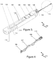
- the first and second actuators 103, 104 may be pushed distally along the axial channel 118, thereby causing the axial and spiral strands 108, 107 to axially advance in the conduit 109 in a distal direction, pushing free of a distal end of the conduit 109, as shown in Figures 3 and 4 , so that the distal end 115 of the device 100 (and the axial and spiral strands 108, 107 in particular) adopts an extended position.
- the spiral strand 107 is caused to adopt an expanded state in which it defines a trawl volume to catch the body as the distal end of the device 100 is withdrawn back through the tubular organ.
- the trawl volume is an open spiral strand structure that tapers radially inwardly in a distal direction, as illustrated in Figures 5 and 6 .
- the spiral strand 107 is caused to adopt its expanded state by moving the second actuator 104 proximally away from the first actuator 103, thereby pulling proximally on axial strand 108 (while the first actuator remains still and spiral strand 107 maintains its position along most of its length apart from at the distal end 115) to cause relative movement between the axial and spiral strands 108, 107.
- a distal length of the spiral strand 107 is formed to have a shape memory consistent with the desired shape to be adopted in the expanded state, such as is shown in Figures 5 and 6 , for example.
- at least a selected distal length of the spiral strand 107 is formed of a shape memory alloy such as nitinol.
- spiral strand 107 may be formed of different sections, not all of which need be spiral in shape.
- spiral strand 107 may include a straight section extending most of the length of the conduit, where it is coupled to a relatively shorter spiral section that is to be exposed and expanded to form the trawl volume.
- Such a straight section may or may not be formed of the same shape memory allow material as the spiral section.
- the axial strand 108 may also be formed of a shape memory alloy, although other bio-compatible metals may be used to form the axial strand 108. Further, it is preferred that the strands 108, 107 be formed of a metallic materials that are compatible with each other in the sense that temperature changes and internal body conditions do not cause corrosion or the generation of electrical current. For this purpose, the same metal may be used for both strands 107, 108.
- the foreign body or the object can be released within a larger tubular structure or organ for normal evacuation from the human or animal body as waste.
- the second actuator 104 can then be pushed distally while the first actuator 103 remains in its distal position, so that the first and second actuators 103, 104 are adjacently positioned, causing the axial strand 108 to progress distally relative to the spiral strand 107 and thereby radially contract the spiral strand 107 about the axial strand 108.
- This contracted state is the same as the extended state depicted in Figures 3 and 4 , where the spiral strand 107 extends generally radially adjacent the axial strand 108.
- both of the first and second actuators 103, 104 can be moved proximally together along the guide channel 118 to the proximal-most positions shown in Figures 1 and 2 to thereby cause the distal end 115 and the spiral and axial strands 107, 108 to again adopt the retracted state.
- the distal end 115 of device 100 Once the distal end 115 of device 100 is in the retracted state, it can be readily withdrawn from the tubular organ and/or endoscope without fear of damage to the organ.
- the axial guide channel 118 and actuators 103, 104 may have complimentary structures that tend to retain the actuators 103, 104 in one of two distal or two proximal positions along the axial guide channel 118.
- These complimentary structures can include a resiliently deflectable portion on each of the actuators 103, 104 or an internal wall of the guide channel 118, arranged to engage with a mating socket on the guide channel wall or actuators 103, 104, respectively.
- each actuator 103, 104 has resiliently deflectable bearings 111, 121 positioned on opposite sides of the actuator 103, 104 and biased outwardly by a bias mechanism 117, such as a spring.
- a bias mechanism 117 such as a spring.
- the actuator 103, 104 When the actuator 103, 104 is positioned so that the bearings 111, 121 mate with opposed sockets 113, 114 formed in the channel wall, the actuator 103, 104 will tend to be retained in that position unless manually pushed away from it.
- This biased retention of the actuators 103, 104 in either a distal or proximal position along the guide channel 118 assists in retaining the device in a desired state and minimises the risk of inadvertent contraction or retraction of the device when it is in the extended or expanded states.
- the mating of the bearings 111, 121 with wall sockets 113, 114 provides a tactile indication to the surgical user of device 100 that the desired position of one or both of the
- the first and second actuators 103, 104 have raised portions on upper surfaces thereof in order to be readily engaged by a thumb of the user while cradling the device body 101 in the user's hand.
- some embodiments may employ more than one spiral strand 107 wound around the axial strand 108 in order to provide a more well-defined trawl volume when such plural second strands are in the expanded state.
- the spiral strand 107 need not be wound around the entire length of the axial strand 108. Rather, the spiral strand 107 should extend spirally around axial strand 108 at least along a length of several centimetres at the distal end 115.
- the term strand or wire is intended to include strands or wires made up of a single filament or multiple filaments.
- Some embodiments relate to a shape memory medical device meant for extracting concrements from tubular organs, specifically stones from the ureter or bile duct.
- Embodiments may be used to reduce the complexity of device management and duration of medical procedures. It simplifies and improves the accuracy of device manipulation as well as increases safety of medical procedures.
- the device “Trawl” contains a manipulator with an adapter installed at the output end of it.
- the adapter has the input and the output end: the input end contains a connection with a feeder of contrast fluid, and the output end contains a flexible catheter.
- Spiral and axial wires made of shape memory alloy, are placed inside the manipulator and the flexible catheter. These wires are capable of moving along the guide axis.
- the top ends of the wires are fixed on the control sliders, while the bottom distal ends are fixed in a cylindrical tip-sleeve, installed outside of the free end of the flexible catheter.
- the control sliders located inside of the manipulator, are capable of joint or independent movement and fixation relative to the guide axis.
- the task to be solved by the invention is to reduce the complexity in use as well as to lessen the duration of medical procedures.
- the invention also aims to simplify the manipulation of the device and improve the accuracy of its control, which would lead to higher safety of medical procedures.
- FIG. 1 shows a position of the device before manipulation
- Figure 2 shows a distal working portion of the device from Figure 1 before manipulation (incision A)
- Figure 3 shows the device prepared for entering a hollow organ with sliders being positioned before capturing a concrement
- Figure 4 shows the device (incision A) once it has entered into a hollow organ before capturing a concrement
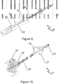
- Figure 5 shows the device once it has entered into a hollow organ and ready to capture a concrement
- Figure 6 shows the distal portion of the device, with a spiral wire fully extended to capture a concrement
- Figure 7 shows a section of the device illustrating movement and fixation of the sliders, corresponding to the position of the device shown in Figure 5 .
- Embodiments generally relate to a device for removing bodies, such as concretions, concrements or foreign bodies from tubular structures, such as tubular organs in a human or animal.
- Embodiments may allow a simplified manipulation, thereby reducing complexity to the surgical user, which may in turn reduce the duration of medical procedures and may increase the accuracy of the instrument, which may lead to improved safety and/or efficacy for medical procedures of this nature.
- tubular organs within a human or animal body there are a number of tubular organs within a human or animal body, to which described embodiments could be applied to retrieve an unwanted or troublesome body, such as in bile ducts, ureter, tracheae, oesophagus, blood vessels and intestines, for example.
- an unwanted or troublesome body such as in bile ducts, ureter, tracheae, oesophagus, blood vessels and intestines, for example.
- embodiments are discussed in relation to procedures to be carried out on human patients, the described embodiments are believed have equal potential for application to animals and other sensitive, organic tubular organs.
- FIGS 1 to 8 illustrate a device 100 "Trawl” for extracting foreign bodies from tubular organs.
- the device 100 comprises a manipulation tool 101, which forms a proximal body of the device 100, and an operational tool 115, which forms a distally extending trawling component of the device 100.
- the manipulator 100 is equipped with an adapter 105 installed at an output end.
- the manipulator 100 is further comprised of a series of circular grooves 116 at the proximal end to aid with grip and manipulation of the manipulator 100 by a surgeon.
- a sleeve is connected to a contrast fluid feeder, which is located at the input end of the adapter 105 at the connection point 106 and an elastic catheter 109 is positioned at the output end of the adaptor 105.
- a spiral wire 107 and an axial wire 108 are located inside a manipulator frame 101 and the flexible catheter 109. Both wires being made from a shape-memory alloy. These wires are able to move along a guide axis 102 within the manipulator frame 101. These wires are able to move along the guide axis 102.
- the ends of these wires 107/108 are fixed on control sliders 103/104, and opposed distal ends are fixed inside a cylindrical tip-sleeve 110 installed outside the free end of the flexible catheter 109.
- Control sliders 103/104 are located in the frame 101 and are capable of joint or independent movement and fixation relative to the guide axis 102.
- the axial wire 108 is located inside the cone of the elastic catheter 109, which is formed by the spiral wire 107.
- the proximal end of spiral wire 107 is permanently affixed to an upper control slider 103 and the proximal end of the axial wire 108 is permanently affixed to a lower control slider 104.
- the distal ends of both wires 107/108 are rigidly attached inside a cylindrical tip-sleeve 110 which is located at the distal, free end of the flexible catheter 109.
- the control sliders 103/104 are located in the manipulator frame 101 and are capable of coincident or independent movement and fixation along the slider guide axis 102.
- the axial wire 107 and the spiral wire 108 are located inside the flexible catheter 109 wherein the spiral wire 108 is wound around the axial wire 107 forming a coiled outer layer around the axial wire 107.
- the spiral wire 108 and axial wire 107 are made of nitinol, a Nickel-Titanium (NiTi) shape-memory alloy, although other shape-memory alloys may be employed instead.
- NiTi Nickel-Titanium
- Nitinol offers a favourable combination of physical and mechanical properties. Aside from its biocompatibility (a similar corrosion resistance to that of stainless steel), it is flexible (low Young's modulus of about 75 GPa), has a high UTS (about 750 - 960 MPa), displays biased stiffness characteristics (stiff in compressions and flexible in tension) and displays its super-elastic behaviour in a similar temperature range to the human body. In these properties it combines many of the advantages of a metal and a plastic into one material, allowing it to be forcibly pushed into position with minimal risk of kinking.
- Nitinol and other shape-memory alloys offer superb elasticity and restorative properties to assist in achieving the desired form in the spiral wire 108.
- the ability to form the appropriate helical profile is necessary to deal with the variety of concrements that may need to be removed from the tubular organs. Some are hard and unyielding, however some may be soft and malleable. Some embodiments of wire trap may apply undue pressure to the concrement, causing it to deform and mould itself around the wire. In this situation the surgeon may be unable to release the concrement or fully retract the catheter 109, causing potential trauma to the tubular organ.
- the spiral wire 108 is given its shape-memory form as a helical coil, reducing the likelihood of uneven pressure being applied to a concrement thus reducing the risk of entangling the concrement and the spiral 108 and axial wires 107.
- control sliders 103/104 are achieved with the help of two spring-loaded balls 111/112, set symmetrically along the guide axis 102, and a pair of grooves 113/114 on the inner side of the frame 101.
- Figure 7 shows the securing of the upper 103 and lower control sliders 104 which is achieved using a pair of spring-loaded balls 111/112 for each slider.
- the balls 111/112 are imbedded within the surface of each individual slider, diametrically opposed either end of a spring 117.
- the spring 117 is used to place a tensioning force on the inner surface of each of the balls 111 and 112.
- the tensile force applied to the balls 111 and 112 is used to lock them in place, so that when the balls 111 and 112 align with the respective locking holes 113 and 114.
- the locking holes 113 and 114 are set symmetrically along the slider guide axis 102 along the length of the slider track 118 within the manipulator frame 101.
- the balls 111/112 can be disengaged from their locked position, using only a force applied by the surgeon's hand, this provides a gentle action and ease of use.
- Distal ends of the spiral 107 and axial wires 108 are securely mounted in the longitudinal channels of the cylindrical tip-sleeve 110.
- the mounting is achieved via pressing direct martensitic transformation in the material of both wires 107/108 in the set temperature range.
- the mounting is formed by directly crimping the wires 107/108 at a temperature within the martensitic transformation range of the shape-memory alloy, as shown in Figure 8 .
- the winding tension of the spiral wire 107 around the axial wire 108 is important.
- the longitudinal distance between the turns of the spiral wire 107 does not exceed the arithmetic mean of the radius of the adjacent turns.
- This ratio provides a gradual increase in the helical coil of the spiral wire 107 and minimises the opportunity for a concrement to slip between the turns of the spiral wire 107.
- the surface of the cylindrical tip-sleeve's end 110 is streamlined to achieve a trauma free shape.
- Figure 8 illustrates a cross-section of the cylindrical tip-sleeve 110, the surface of the end of which is streamlined to achieve a trauma free shape on ingress and egress of the operational tool 115.
- the tip-sleeve end 110 has a rounded shape, and the cross-sectional drawing shows the internal crimping mechanism used to secure the ends of the spiral wire 107 and axial wire 108.
- the tip-sleeve 110 is shown in Figures 2 , 4 and 6 as a pellet shape; wherein the distal end is closed and the proximal end is open, to receive the two wires 107 and 108.
- tip-sleeve 110 For tip-sleeve 110, a streamlined and smooth surface finish is preferred and minimal, if any, sharp radii are desirable, as these may increase trauma to the tubular organ on ingress and egress.
- a bulb shaped tip-sleeve 110 has also been contemplated, whereby the maximum circumference of the tip-sleeve 110 is at a central point along the longitudinal axis of the tip-sleeve and the circumference of the tip-sleeve reduces in both directions along the longitudinal axis from the maximum point.
- This embodiment provides a tip-sleeve with a distal end that is a solid bulb and a proximal end (where the wires 107 and 108 enter the tip-sleeve) of lesser circumference than the maximum circumference of the tip-sleeve.
- This shape minimises trauma to the tubular organ both in forwards and rearwards travel of the tip-sleeve 110.
- the cross-section shown in Figure 8 illustrates a generally circular section, with a straight channel cut from the external surface of the tip-sleeve 110, with an adjacent central cavity formed within the tip-sleeve 110.
- the straight channel is positioned eccentrically on the tip-sleeve 100 cross-section although it is contemplated that different locations for the straight channel may be configured.
- the straight channel facilitates the insertion of the wires 107 and 108 into the tip-sleeve 110 prior to the crimping operation.
- the central cavity is formed with a cross-section resembling two overlapping circles of different diameters.
- the smaller diameter cavity section is sized to receive the smaller gauge wire, generally the spiral wire 107, while the larger diameter cavity is sized to receive the larger gauge wire, generally the axial wire 108.
- a series of small undulations, or teeth or nubs may be formed in the internal surfaces of the tip-sleeve 110 internal cavities. These teeth serve to increase friction and thereby grip, however, they are not shown in Figure 8 .
- Crimping the two wires 107 and 108 is a very reliable method of joining the two wires and also a reliable method of securing the tip-sleeve 110. Crimping is a cheap, reliable and efficient method of joining Nitinol wires and minimises the risk of disconnection during use, which would have serious implications for the patient.
- other embodiments may employ a different means of affixing the distal ends of spiral and axial wired 107, 108 relative to each other and need not cause direct contact between the two wires, provided there is minimal risk of the wires coming loose.
- the stiffness of the elastic catheter's axial wire 108 exceeds the stiffness of the spiral wire 107.
- the axial wire 107 is of a heavier gauge than that of the spiral wire 108 ensuring that the stiffness (resistance to deformation) of the axial wire108 exceeds the stiffness of the spiral wire 107.
- the outer diameter of the cylindrical tip-sleeve 110 is at least equal to the inner diameter of the flexible catheter 109 and does not exceed its outer diameter.
- the flexible catheter 109 is about 1mm to 7mm in diameter, depending on the procedure to be carried out and the relative size of the organ to be entered.
- the device “Trawl” includes ( Fig. 1-6 ) a manipulator with the frame 101, an axial guide 102 for the spiral wire 107 and the axial wire 108, both mounted inside the frame 101 and made from a shape memory alloy, such as nitinol, thermally treated for super elasticity. If a different material is used, which does not possess super elasticity, the device will be not be operating.
- a shape memory alloy such as nitinol
- the wires 107/108 may be made from a shape memory alloy, such as Nitinol, thermally treated for super elasticity; however other shape-memory alloys may be used in place of Nitinol.
- a shape memory alloy such as Nitinol, thermally treated for super elasticity; however other shape-memory alloys may be used in place of Nitinol.
- proximal end of axial wire 108 is fixed inside the slider 104, while the proximal end of the spiral wire 107 is fixed inside a different slider 103.
- proximal end of axial wire 108 is fixed inside a lower slider 104, while the proximal end of the spiral wire 107 is fixed inside an upper slider 103.
- the adapter 105 is installed at the output end of the frame 101.
- the adapter hosts a connection 106, with the feeder of contrast fluid (not shown in the drawing) installed at the input end of the adapter.
- a syringe can easily be used as a feeder of the contrast fluid.
- the adapter 105 is installed at the distal end of the manipulator frame 101, and may have a body of varying length.
- Figure 9 illustrates an embodiment of the device 100, where the adaptor 105 is extended, to effectively increase the rigid body portion 101 of the device 100 and extend the location of the connection point 106 from the device frame 101.
- the adapter 105 hosts a connection 106, for a feeder of contrast fluid (not shown in the drawing) installed at a point on the adapter 105 body.
- a syringe or other similar device may then be used as a feeder of a contrast fluid for the desired procedure.
- the contrast fluid flows through the flexible catheter 109 and is released into the body proximate the tip-sleeve 110, where the contrast fluid there aids the surgeon by improving visibility of the operation site.
- the adaptor 105 need not be directly connected to the manipulator frame 101, as long as there are manual controls for the wires 107 and 108 provided for between the manipulator frame 101 and the adaptor 105.
- the flexible catheter 109 is attached to the output end of the adapter 105.
- the wires 107 and 108 are partially located inside the catheter 109 and are capable of axial movement.
- the wires 107 and 108 are capable of movement relative to each other and may also be manoeuvred through the catheter 109 together by applying pressure to the manipulator frame 101.
- the distal ends of the wires 107 and 108 are connected with the cylindrical tip-sleeve 110 installed at free end of the flexible catheter 109.
- connection between the distal ends of the wires 107 and 108 is permanently affixed into the cylindrical tip-sleeve 110 located at the distal (free) end of the flexible catheter 109.
- Sliders 103 and 104 are located in the frame 101 and are capable of joint or independent movement and fixation relative to the guide axis 102 of the frame 101.
- the mechanism of movement and fixation of the sliders 103 and 104 is made of the two spring-loaded balls 111 and 112, set symmetrically to the guide axis 102 and a pair of grooves 113 and 114, set on the internal wall of the frame 101 as illustrated by Figure 7 .
- Upper slider 103 and lower slider 104 are positioned within the frame 101 and are free to move together or independently. They are also capable of being jointly or independently relative to the slider guide axis 102 of the manipulator frame 101.
- the locking mechanism of the sliders 103 and 104 is comprised of two spring-loaded balls 111 and 112, symmetrically aligned to the slider guide axis 102.
- the slider guide axis 102 has a series of pairs of grooves 113 and 114, located on the internal walls of the manipulator frame 101 as illustrated by Figure 7 . This allows the sliders 103 and 104 to be locked in position at multiple points along the slider track 118.
- This mechanism of movement and fixation of the sliders 103 and 104 provides tangible control of the position of these sliders: the extreme position of the sliders can be felt well tacitly (tactilely) when the balls 111 and 112 of the sliders are in the holes 113 and 114.
- this mechanism also provides a sound control: when the balls 111 and 112 are locked in the holes 113 and 114, they click.
- the control mechanism of the sliders 103 and 104 provides delicate control and indication of the position of the sliders: the extremities of the positions of the sliders can be felt by the surgeon as the balls 111 and 112 in the sliders 103/104 align and spring into corresponding grooves 113 and 114. In addition to being able to feel the locking of the balls 111/112, this mechanism also provides a sound indicator as the balls 111 and 112 make an audible "click" upon locking into grooves 113 and 114.
- the surgeon is able to manipulate the trawl 100 by looking at a monitor screen of an X-ray machine, which contributes to better focus on the proper course of surgery.
- the tactile feedback and engagement sounds of the device 100 are used as a guide for the surgeon however the position of the tip-sleeve 110 and wires 107/108 within the tubular organ, relative to the concrement, is verified and adjusted from the x-ray images as seen on the x-ray monitor.
- the distal ends of the wires 107 and 108 are installed in the longitudinal channels of the cylindrical tip-sleeve 110 via pressure crimping.
- This technique allows the cohesive force to significantly exceed the capability of the existing analogues inventions.
- the pressure crimping of both wires 107/108 inside the tip-sleeve 110 is conducted in a temperature range of direct martensitic transformation (+25 to - 20°C).
- a temperature range of direct martensitic transformation (+25 to - 20°C.
- the required efforts to operate the device are relatively minor.
- the material reaches the temperature of the human body, it develops a reactive pressure of up to 500 MPa achieving extremely reliable fixation of the ends of the wires inside the tip-sleeve 110.
- Such technology ensures the reliability of the device in operation and prevents patient injury during surgeries.
- the two wires 107/108 are not firmly attached and the connection between them is severed trauma to the tubular organ may be caused.
- the tip-sleeve 110 is not suitably rounded or streamlined which can cause trauma when manoeuvring through the tubular organ, increasing the possibility of catching or tearing at any internal folds within the organ.
- the longitudinal distance between the turns of the screw wire 107 will not exceed the arithmetic mean of the adjacent turns' radii, which prevents a concrement captured by the Trawl 100 to be lost. It also limits the undue expansion the wires. In particular undue expansion of the spiral wire 107.
- the outer diameter of the cylindrical tip-sleeve 110 is at least equal to the inner diameter of the flexible catheter 109 and does not exceed the catheter's outer diameter. These specifications allow the tip-sleeve 110 to always remain outside of the catheter 109. In other embodiments the outer diameter of the tip-sleeve 110 is at least equal to the inner diameter of the catheter 109, and may be larger than that of the outer diameter of the catheter 109 providing a rounded or bulbous tip-sleeve profile. The maximum diameter of the tip-sleeve 110 must be less than that of the endoscope, if the device 115 is to be inserted into the tubular organ through an endoscope and to travel freely within the channel of the endoscope.
- the device 115 is not introduced into the tubular organ alone, but is instead inserted through an endoscope already correctly positioned within the tubular organ.
- an endoscope may be left in position and used for the ingress and egress of several medical instruments to facilitate multiple complimentary procedures.
- the ends of the cylindrical tip-sleeve 110 are streamlined, which allows for trauma free entry of the device 115 into hollow organs.
- the tip-sleeve 110 is the most likely component to cause trauma to a patient, both on ingress of the device and egress, and further while travelling along tubular organs where there is a potential for the tip-sleeve to catch if not appropriately shaped.
- the stiffness of the axial wire 108 exceeds the stiffness of the spiral wire 107 to allow the device to transition from the position described in Figures 1 and 2 to the position in Figures 3 and 4 .
- the device is brought into Position 1.
- the slider 103 is pressed, which leads to both sliders 103 and 104 being pushed back, i.e. the extreme left or proximal position on Figure 1 .
- Working part of the trap is moved back into the catheter 109.
- a surgeon can feel the fixation of the device in the Position 1 tacitly, as confirmed by the click of the balls 111 and 112 moving into the holes 113/114.
- the upper slider 103 is pressed and pulled down towards the proximal end of the manipulator 100. This causes both sliders 103 and 104 to be pushed backwards, i.e. the position in Figure 1 .
- the working part of the trap i.e. the spiral wire 107 is pulled back into the flexible catheter 109.
- a surgeon can feel the movement of the axial 108 and spiral wire 107 tacitly through the upper and lower sliders 103/104, and the motion is confirmed by the audible click of the balls 111 and 112 as they move and lock into the holes 113 and 114.
- the device is brought into Position 2. To do this, the slider 104 is pressed, which leads to both sliders 103 and 104 being pushed forward (right). At the same time the working part of the device is advancing from the catheter 109 and moving towards a concrement. A surgeon can feel the fixation of the device in the Position 2 tacitly, as confirmed by the click of the balls 111 and 112 moving into the holes 113/114.
- the device is brought into Position 2 by pressing the slider 104 forwards towards the distal end of the manipulator 100 which causes both sliders 103 and 104 to be moved to the distal position.
- This slider motion extends the operational tool 115 of the device from the catheter 109, moving it towards a concrement to be removed.
- the tip-sleeve 110 will need to be extended past the concrement within the tubular organ, in order to facilitate capture of said concrement.
- a surgeon can physically feel the location of the operational tool 115 as it reaches Position 2. This location is also confirmed by the audible click of the balls 111 and 112 moving into the locking holes 113 and 114.
- the device is brought into Position 3.
- a surgeon can feel the fixation of the device in the Position 3 tacitly, as confirmed by the click of the balls (11) and (12) moving into the holes (13) - one before far left.
- the spiral wire (7) is forming a spiral trawl-trap.
- a concrement is captured into the basket by pulling the catheter (9). Then a concrement is pulled into the channel of the endoscope, which is extracted out.
- the device is brought into Position 3 by moving slider 104 back towards the proximal end of the manipulator 100.
- the tip-sleeve 110 at this time is in a position behind the concrement, having been extended past the concrement when inserted in to the tubular organ.
- Moving slider 104 retracts the axial wire 108 (individually controlled by the slider 104), and the excess length of the spiral wire 107, relative to the shortened axial wire 108, begins to form a spiral trawl-trap centred around the taught axial wire 108.
- a concrement may be captured by the trawl-trap by gently manoeuvring the catheter 109 so the tubular organ becomes blocked by the trawl-trap.
- the captured concrement is then positioned in front of the trawl-trap and may then be pulled or trawled out of the tubular organ in a direction towards the flexible catheter 109.
- the concrement is gently trawled from the tubular organ until a junction is found with a larger organ, such as the intestine, where the concrement is then gently guided into the larger organ. From this position the body will naturally dispose of the concrement having removed the capacity for the concrement to block the smaller tubular organ.
- the device 115 is then retracted from the organ (or endoscope). A surgeon will physically feel the movement of the device into Position 3 through contact with the slider 104, and as before the locking mechanism of the slider will be confirmed by an audible click of the balls 111 and 112 moving into the locking holes 113 and 114.
- a concrement cannot be retrieved, it can be released without injuring a patient. To do this, the device is moved into Position 2. The spiral wire 107 is extended as it moves in front of the axial wire 108 and a concrement is released.
- the mechanical force applied by the sliders 103 and 104 is sufficient to return the super elastic wires 107 and 108 back to their original, compact form and position to be retracted back into the flexible catheter 109.
- the device is brought into Position 1 ( Figures 1 and 2 ). To do this, the slider 103 is pressed on and both sliders 103 and 104 move back into the proximal (left) position. The working part of the trap is moved into the catheter 109 and the device is extracted.
Landscapes
- Health & Medical Sciences (AREA)
- Life Sciences & Earth Sciences (AREA)
- Surgery (AREA)
- Animal Behavior & Ethology (AREA)
- Veterinary Medicine (AREA)
- Public Health (AREA)
- General Health & Medical Sciences (AREA)
- Biomedical Technology (AREA)
- Heart & Thoracic Surgery (AREA)
- Engineering & Computer Science (AREA)
- Molecular Biology (AREA)
- Medical Informatics (AREA)
- Nuclear Medicine, Radiotherapy & Molecular Imaging (AREA)
- Vascular Medicine (AREA)
- Orthopedic Medicine & Surgery (AREA)
- Chemical & Material Sciences (AREA)
- Inorganic Chemistry (AREA)
- Epidemiology (AREA)
- Anesthesiology (AREA)
- Hematology (AREA)
- Surgical Instruments (AREA)
- Endoscopes (AREA)
- Media Introduction/Drainage Providing Device (AREA)
Claims (15)
- Vorrichtung zur Entnahme eines Körpers aus einer rohrförmigen Struktur, die Vorrichtung ein proximales Ende und ein distales Ende (115) aufweisend und umfassend:einen Vorrichtungskörper (101) an dem proximalen Ende;einen Kanal (109), der sich von dem Vorrichtungskörper weg zu dem distalen Ende erstreckt und dimensioniert ist in die rohrförmige Struktur aufnehmbar zu sein;mindestens einen Aktor (103, 104), der bedienbar mit dem Vorrichtungskörper verbunden ist;einen ersten Draht (108), der sich zumindest teilweise durch den Kanal erstreckt;einen zweiten Draht (107), der sich zumindest teilweise durch den Kanal erstreckt;wobei der erste und zweite Draht an dem distalen Ende der Vorrichtung befestigt sind, und wobei der zweite Draht um den ersten Draht herum gewunden ist zumindest entlang einer distalen Länge des ersten Drahts;wobei der mindestens eine Aktor bedienbar ist um zu bewirken, dass der zweite Draht eine expandierte Stellung einnimmt, in der der zweite Draht ein Schleppvolumen definiert um den Körper zur Entnahme des Körpers aus der rohrförmigen Struktur zu greifen;dadurch gekennzeichnet, dass der mindestens eine Aktor einen ersten (104) und einen zweiten (103) Aktor umfasst, wobei der erste und der zweite Aktor unabhängig bedienbar sind, wobei der erste Draht mit dem ersten Aktor ist und der zweite Draht mit dem zweiten Aktor verbunden ist.
- Vorrichtung nach Anspruch 1, wobei das Schleppvolumen durch eine Spiralform des zweiten Drahts in der expandierten Stellung definiert ist.
- Vorrichtung nach Anspruch 1 oder Anspruch 2, wobei das Schleppvolumen nach innen auf den ersten Draht zu in Richtung des distalen Endes konisch zuläuft.
- Vorrichtung nach einem der Ansprüche 1 bis 3, wobei der zweite Draht aus einer Formgedächtnis-Legierung gebildet ist zumindest entlang einer distalen Länge des zweiten Drahts, wobei die distale Länge des zweiten Drahts gebildet ist um ein Formgedächtnis aufzuweisen, dass das Schleppvolumen definiert.
- Vorrichtung nach einem der Ansprüche 1 bis 4, wobei sich der zweite Draht in der expandierten Stellung radial über einen äußeren Durchmesser des Kanals hinaus erstreckt.
- Vorrichtung nach einem der Ansprüche 1 bis 5, wobei der mindestens eine Aktor bedienbar ist um zu bewirken, dass der zweite Draht eine kontrahierte Stellung einnimmt, in der sich der zweite Draht radial benachbart zu dem ersten Draht erstreckt.
- Vorrichtung nach einem der Ansprüche 1 bis 6, wobei der erste Draht einen größeren Durchmesser und eine größere Steifigkeit aufweist als ein Durchmesser und eine Steifigkeit des zweiten Drahts.
- Vorrichtung nach einem der Ansprüche 1 bis 7, ferner umfassend eine distale Spitzenhülse (110) angeordnet an einer distalen Extremität der Vorrichtung, wobei die distale Spitzenhülse distale Enden des ersten und zweiten Drahts aufnimmt, wobei die distale Spitzenhülse einen Durchmesser aufweist, der größer ist als oder genauso groß ist wie ein Durchmesser des Kanals; wobei die distale Spitzenhülse die distalen Enden des ersten und zweiten Drahts in einer festen Verbindung zueinander hält, wobei diese zusammengeklemmt oder zusammengecrimpt werden, und wobei die distale Spitzenhülse ein gerundetes äußeres Profil hat.
- Vorrichtung nach einem der Ansprüche 1 bis 8, wobei mindestens eins von:der mindestens eine Aktor bedienbar ist um zu bewirken, dass der erste und zweite Draht eine eingezogene Stellung einnehmen, in der distale Längen des ersten und zweiten Drahts im Wesentlichen in dem Kanal eingeschlossen sind, wobei in der eingezogenen Stellung der Kanal den zweiten Draht daran hindert die expandierte Stellung einzunehmen; undwobei der mindestens eine Aktor bedienbar ist um zu bewirken, dass der erste und zweite Draht eine ausgestreckte Stellung einnehmen, in der distale Längen des ersten und zweiten Drahts im Wesentlichen durch den Kanal unbedeckt sind, wobei in der ausgestreckten Stellung der Kanal den zweiten Draht nicht daran hindert die expandierte Stellung einzunehmen.
- Vorrichtung nach einem der Ansprüche 1 bis 9, wobei eine Relativbewegung zwischen dem ersten und zweiten Aktor eine Relativbewegung zwischen dem ersten und zweiten Draht bewirkt, und wobei der zweite Draht veranlasst wird die expandierte Stellung in Reaktion auf die Relativbewegung zwischen dem ersten und zweiten Aktor einzunehmen.
- Vorrichtung nach einem der Ansprüche 1 bis 10, wobei der mindestens eine Aktor beweglich ist relativ zu dem Vorrichtungskörper und mindestens einen Eingriffabschnitt (111, 112) aufweist um mit mindestens einer komplementären Struktur (113, 114) des Vorrichtungskörpers in Eingriff zu stehen, sodass, wenn der mindestens eine Eingriffabschnitt mit der mindestens einen komplementären Struktur in Eingriff steht, der mindestens eine Aktor dazu tendiert relativ zum Vorrichtungskörper in Position zu bleiben.
- Vorrichtung nach einem der Ansprüche 1 bis 11, wobei der mindestens eine Aktor verschiebbar beweglich ist relativ zu dem Vorrichtungskörper, wobei der mindestens eine Aktor verschiebbar beweglich ist in einer axialen Richtung um eine axiale Bewegung mindestens eines des ersten Drahts und des zweiten Drahts zu bewirken.
- Vorrichtung nach einem der Ansprüche 1 bis 12, wobei der Kanal ein Lumen definiert, worin sich der erste und der zweite Draht erstrecken, wobei das Lumen und der erste und zweite Draht so dimensioniert sind, dass ein Fluid durch das Lumen zum distalen Ende hin fließen kann, die Vorrichtung ferner einen Fluideinlass (106) angeordnet an dem Vorrichtungskörper umfasst, der Fluideinlass in fluidischer Verbindung mit dem Lumen stehend, sodass ein Kontrastfluid von dem Fluideinlass zu dem distalen Ende durch das Lumen geführt werden kann.
- Vorrichtung nach einem der Ansprüche 1 bis 13, wobei der Kanal so dimensioniert ist, dass es in einen Instrumentenkanal eines Endoskops aufgenommen werden kann.
- Vorrichtung nach einem der Ansprüche 1 bis 14, wobei der erste und zweite Draht metallische Drähte gebildet aus biokompatiblem Material sind.
Applications Claiming Priority (2)
| Application Number | Priority Date | Filing Date | Title |
|---|---|---|---|
| PCT/RU2010/000711 WO2012074426A1 (en) | 2010-11-30 | 2010-11-30 | Device for concrements extraction from tubular structures |
| PCT/AU2011/001561 WO2012071620A1 (en) | 2010-11-30 | 2011-11-30 | Device for retrieving a body from a tubular structure |
Publications (3)
| Publication Number | Publication Date |
|---|---|
| EP2645945A1 EP2645945A1 (de) | 2013-10-09 |
| EP2645945A4 EP2645945A4 (de) | 2014-10-29 |
| EP2645945B1 true EP2645945B1 (de) | 2019-12-11 |
Family
ID=46171095
Family Applications (1)
| Application Number | Title | Priority Date | Filing Date |
|---|---|---|---|
| EP11845817.3A Active EP2645945B1 (de) | 2010-11-30 | 2011-11-30 | Vorrichtung zur entnahme eines körpers aus einer rohrförmigen struktur |
Country Status (11)
| Country | Link |
|---|---|
| US (1) | US11259822B2 (de) |
| EP (1) | EP2645945B1 (de) |
| JP (1) | JP6444031B2 (de) |
| KR (2) | KR101992283B1 (de) |
| CN (1) | CN103370019B (de) |
| AU (1) | AU2011335890B2 (de) |
| BR (1) | BR112013013452A2 (de) |
| CA (1) | CA2856745C (de) |
| EA (1) | EA031811B1 (de) |
| RU (1) | RU2492824C2 (de) |
| WO (2) | WO2012074426A1 (de) |
Families Citing this family (9)
| Publication number | Priority date | Publication date | Assignee | Title |
|---|---|---|---|---|
| EP3081177B1 (de) * | 2013-12-12 | 2019-02-27 | Olympus Corporation | Korbartige greifzange |
| US10702299B2 (en) * | 2014-07-03 | 2020-07-07 | Taryag Medical Ltd. | Atherectomy device |
| EP3692933B1 (de) | 2016-05-06 | 2023-09-27 | Boston Scientific Scimed, Inc. | Medizinische systeme und vorrichtungen |
| CN106667420B (zh) * | 2017-01-24 | 2018-06-01 | 长春艾迪尔医用科技发展有限公司 | 一种可调节可弯曲的鼻窦镜 |
| JP7329059B2 (ja) * | 2019-02-22 | 2023-08-17 | ダブリュ.エル.ゴア アンド アソシエイツ,インコーポレイティド | 作動ライン格納システム及び方法 |
| CN113040870B (zh) * | 2019-12-26 | 2023-03-21 | 先健科技(深圳)有限公司 | 造口器械 |
| CN111839659A (zh) * | 2020-07-23 | 2020-10-30 | 玮铭医疗器械(上海)有限公司 | 一种用于颅内大血管栓塞的抽吸导管装置 |
| CN112603504B (zh) * | 2020-12-25 | 2022-06-03 | 秦彩丽 | 一种帽子型鼻腔异物专用去除装置 |
| CN115844491B (zh) * | 2022-12-06 | 2023-05-16 | 杭州亿科医疗科技有限公司 | 一种取栓网收缩扩张可控的取栓装置 |
Family Cites Families (28)
| Publication number | Priority date | Publication date | Assignee | Title |
|---|---|---|---|---|
| SE325986B (de) * | 1965-07-05 | 1970-07-13 | T Almen | |
| US4706671A (en) * | 1985-05-02 | 1987-11-17 | Weinrib Harry P | Catheter with coiled tip |
| US5171314A (en) * | 1990-07-24 | 1992-12-15 | Andrew Surgical, Inc. | Surgical snare |
| RU2058115C1 (ru) * | 1992-11-12 | 1996-04-20 | Попович Сергей Николаевич | Устройство для удаления конкрементов из полых органов |
| US5527326A (en) * | 1992-12-29 | 1996-06-18 | Thomas J. Fogarty | Vessel deposit shearing apparatus |
| RU2153856C2 (ru) * | 1996-01-17 | 2000-08-10 | Московский государственный институт стали и сплавов (технологический университет) | Устройство для извлечения инородных тел из полых органов |
| US5895398A (en) * | 1996-02-02 | 1999-04-20 | The Regents Of The University Of California | Method of using a clot capture coil |
| US5972019A (en) * | 1996-07-25 | 1999-10-26 | Target Therapeutics, Inc. | Mechanical clot treatment device |
| EP0955912A1 (de) | 1996-12-31 | 1999-11-17 | Cook Urological Inc. | Verschlusssystem mit geflochtenem filter fur harnleitersteine |
| JPH1147141A (ja) | 1997-08-04 | 1999-02-23 | Olympus Optical Co Ltd | 体腔内異物回収用把持具 |
| US6203552B1 (en) * | 1998-03-20 | 2001-03-20 | Cook Urological Incorporated | Minimally invasive medical retrieval device |
| US6511492B1 (en) * | 1998-05-01 | 2003-01-28 | Microvention, Inc. | Embolectomy catheters and methods for treating stroke and other small vessel thromboembolic disorders |
| RU2145488C1 (ru) * | 1998-05-20 | 2000-02-20 | Московский государственный институт стали и сплавов (технологический университет) | Устройство для извлечения инородных тел из полых органов "трал" (варианты) |
| US6190394B1 (en) * | 1999-11-05 | 2001-02-20 | Annex Medical, Inc. | Medical retrieval basket |
| US6258101B1 (en) | 2000-03-24 | 2001-07-10 | Lacey Manufacturing Company, Inc. | Instrument for deploying surgical devices |
| US20010031981A1 (en) * | 2000-03-31 | 2001-10-18 | Evans Michael A. | Method and device for locating guidewire and treating chronic total occlusions |
| US20040073243A1 (en) | 2000-06-29 | 2004-04-15 | Concentric Medical, Inc., A Delaware Corporation | Systems, methods and devices for removing obstructions from a blood vessel |
| ES2438147T3 (es) * | 2001-01-09 | 2014-01-16 | Microvention, Inc. | Catéteres de embolectomía |
| US20040153095A1 (en) * | 2003-01-31 | 2004-08-05 | Seddon J. Michael | Method and apparatus for removing urinary tract stones |
| US7625346B2 (en) * | 2003-05-30 | 2009-12-01 | Boston Scientific Scimed, Inc. | Transbronchial needle aspiration device |
| US20060173468A1 (en) * | 2005-01-28 | 2006-08-03 | Marc Simmon | Obturator introducer with snare |
| US7955344B2 (en) | 2005-04-01 | 2011-06-07 | Nexgen Medical Systems, Inc. | Thrombus removal system and process |
| CA2651175A1 (en) * | 2006-05-03 | 2007-11-15 | Wilson-Cook Medical, Inc. | Lithotripsy compatible wire basket |
| DE112009001442T5 (de) * | 2008-06-09 | 2011-06-16 | Access Point Technologies | Medizinisches Behandlungsinstrument für ein rohrförmiges Organ |
| AU2009266808B2 (en) * | 2008-07-03 | 2014-07-10 | Teleflex Life Sciences Limited | Apparatus and methods for treating obstructions within body lumens |
| WO2010009407A1 (en) * | 2008-07-17 | 2010-01-21 | Tyco Healthcare Group Lp | Spirally conformable infusion catheter |
| JP4510125B1 (ja) | 2009-02-20 | 2010-07-21 | 株式会社ウィルファイン | 血管内の血栓捕獲器 |
| EP2456504B1 (de) * | 2009-07-23 | 2019-06-19 | Hotspur Technologies, Inc | Vorrichtung zur behandlung von obstruktionen in körperlumen |
-
2010
- 2010-11-30 WO PCT/RU2010/000711 patent/WO2012074426A1/en active Application Filing
- 2010-11-30 RU RU2010150010/14A patent/RU2492824C2/ru active
-
2011
- 2011-11-30 US US13/990,638 patent/US11259822B2/en active Active
- 2011-11-30 EP EP11845817.3A patent/EP2645945B1/de active Active
- 2011-11-30 BR BR112013013452A patent/BR112013013452A2/pt not_active Application Discontinuation
- 2011-11-30 JP JP2013541151A patent/JP6444031B2/ja not_active Expired - Fee Related
- 2011-11-30 CA CA2856745A patent/CA2856745C/en active Active
- 2011-11-30 CN CN201180062923.4A patent/CN103370019B/zh active Active
- 2011-11-30 WO PCT/AU2011/001561 patent/WO2012071620A1/en active Application Filing
- 2011-11-30 KR KR1020187026412A patent/KR101992283B1/ko active IP Right Grant
- 2011-11-30 EA EA201390798A patent/EA031811B1/ru not_active IP Right Cessation
- 2011-11-30 KR KR1020137016257A patent/KR20140008319A/ko active Search and Examination
- 2011-11-30 AU AU2011335890A patent/AU2011335890B2/en not_active Ceased
Non-Patent Citations (1)
| Title |
|---|
| None * |
Also Published As
| Publication number | Publication date |
|---|---|
| BR112013013452A2 (pt) | 2016-10-18 |
| KR101992283B1 (ko) | 2019-06-24 |
| JP6444031B2 (ja) | 2018-12-26 |
| CN103370019A (zh) | 2013-10-23 |
| CA2856745A1 (en) | 2012-06-07 |
| US11259822B2 (en) | 2022-03-01 |
| EA031811B1 (ru) | 2019-02-28 |
| WO2012074426A1 (en) | 2012-06-07 |
| AU2011335890B2 (en) | 2016-07-14 |
| EP2645945A1 (de) | 2013-10-09 |
| KR20140008319A (ko) | 2014-01-21 |
| AU2011335890A1 (en) | 2013-06-20 |
| CA2856745C (en) | 2018-10-02 |
| RU2492824C2 (ru) | 2013-09-20 |
| CN103370019B (zh) | 2016-06-08 |
| JP2014500082A (ja) | 2014-01-09 |
| EP2645945A4 (de) | 2014-10-29 |
| US20140066948A1 (en) | 2014-03-06 |
| EA201390798A1 (ru) | 2014-11-28 |
| KR20180107267A (ko) | 2018-10-01 |
| WO2012071620A1 (en) | 2012-06-07 |
| RU2010150010A (ru) | 2013-06-10 |
Similar Documents
| Publication | Publication Date | Title |
|---|---|---|
| EP2645945B1 (de) | Vorrichtung zur entnahme eines körpers aus einer rohrförmigen struktur | |
| US7798992B2 (en) | Lumen traversing device | |
| US9320531B2 (en) | Medical device handles and related methods of use | |
| JP6181235B2 (ja) | 異物を処理するための医療用装置 | |
| JP2017526463A (ja) | 回収装置 | |
| JP5186659B2 (ja) | 医療用握持装置 | |
| CA2402407A1 (en) | Retrieval basket with releasable tip | |
| EP1832250A1 (de) | Einrichtung zum Entfernen eines Stents | |
| US10105153B2 (en) | Multifunction retrieval devices and related methods | |
| WO2013123304A1 (en) | Stone retrieval device | |
| JP6749336B2 (ja) | 回収デバイス及び関連の使用方法 | |
| EP2757979B1 (de) | Schlingensystem | |
| CN109984876B (zh) | 用于肺减容植入体的回收系统和鞘管 | |
| EP3581123A1 (de) | Perkutaner extraktor mit laseranordnung | |
| JP2016101315A (ja) | 医療用デバイス | |
| WO2015032729A1 (en) | Access sheath | |
| JPH02111353A (ja) | 内視鏡用把持具 |
Legal Events
| Date | Code | Title | Description |
|---|---|---|---|
| PUAI | Public reference made under article 153(3) epc to a published international application that has entered the european phase |
Free format text: ORIGINAL CODE: 0009012 |
|
| 17P | Request for examination filed |
Effective date: 20130530 |
|
| AK | Designated contracting states |
Kind code of ref document: A1 Designated state(s): AL AT BE BG CH CY CZ DE DK EE ES FI FR GB GR HR HU IE IS IT LI LT LU LV MC MK MT NL NO PL PT RO RS SE SI SK SM TR |
|
| REG | Reference to a national code |
Ref country code: HK Ref legal event code: DE Ref document number: 1186367 Country of ref document: HK |
|
| A4 | Supplementary search report drawn up and despatched |
Effective date: 20140926 |
|
| RIC1 | Information provided on ipc code assigned before grant |
Ipc: A61B 17/50 20060101AFI20140922BHEP Ipc: A61B 17/22 20060101ALI20140922BHEP |
|
| RAP1 | Party data changed (applicant data changed or rights of an application transferred) |
Owner name: NATIONAL UNIVERSITY OF SCIENCE AND TECHNOLOGY MISI |
|
| RAP1 | Party data changed (applicant data changed or rights of an application transferred) |
Owner name: GLOBETEK 2000 PTY LTD Owner name: THE FEDERAL STATE AUTONOMOUS EDUCATIONAL INSTITUTI |
|
| RIC1 | Information provided on ipc code assigned before grant |
Ipc: A61M 5/00 20060101ALI20190423BHEP Ipc: A61B 17/50 20060101AFI20190423BHEP Ipc: A61B 17/00 20060101ALI20190423BHEP Ipc: A61B 17/22 20060101ALI20190423BHEP Ipc: A61B 17/221 20060101ALI20190423BHEP |
|
| GRAP | Despatch of communication of intention to grant a patent |
Free format text: ORIGINAL CODE: EPIDOSNIGR1 |
|
| STAA | Information on the status of an ep patent application or granted ep patent |
Free format text: STATUS: GRANT OF PATENT IS INTENDED |
|
| INTG | Intention to grant announced |
Effective date: 20190625 |
|
| GRAS | Grant fee paid |
Free format text: ORIGINAL CODE: EPIDOSNIGR3 |
|
| GRAA | (expected) grant |
Free format text: ORIGINAL CODE: 0009210 |
|
| STAA | Information on the status of an ep patent application or granted ep patent |
Free format text: STATUS: THE PATENT HAS BEEN GRANTED |
|
| AK | Designated contracting states |
Kind code of ref document: B1 Designated state(s): AL AT BE BG CH CY CZ DE DK EE ES FI FR GB GR HR HU IE IS IT LI LT LU LV MC MK MT NL NO PL PT RO RS SE SI SK SM TR |
|
| REG | Reference to a national code |
Ref country code: GB Ref legal event code: FG4D |
|
| REG | Reference to a national code |
Ref country code: CH Ref legal event code: EP |
|
| REG | Reference to a national code |
Ref country code: AT Ref legal event code: REF Ref document number: 1211372 Country of ref document: AT Kind code of ref document: T Effective date: 20191215 |
|
| REG | Reference to a national code |
Ref country code: DE Ref legal event code: R096 Ref document number: 602011064009 Country of ref document: DE |
|
| REG | Reference to a national code |
Ref country code: IE Ref legal event code: FG4D |
|
| REG | Reference to a national code |
Ref country code: NL Ref legal event code: FP |
|
| REG | Reference to a national code |
Ref country code: LT Ref legal event code: MG4D |
|
| PG25 | Lapsed in a contracting state [announced via postgrant information from national office to epo] |
Ref country code: NO Free format text: LAPSE BECAUSE OF FAILURE TO SUBMIT A TRANSLATION OF THE DESCRIPTION OR TO PAY THE FEE WITHIN THE PRESCRIBED TIME-LIMIT Effective date: 20200311 Ref country code: GR Free format text: LAPSE BECAUSE OF FAILURE TO SUBMIT A TRANSLATION OF THE DESCRIPTION OR TO PAY THE FEE WITHIN THE PRESCRIBED TIME-LIMIT Effective date: 20200312 Ref country code: FI Free format text: LAPSE BECAUSE OF FAILURE TO SUBMIT A TRANSLATION OF THE DESCRIPTION OR TO PAY THE FEE WITHIN THE PRESCRIBED TIME-LIMIT Effective date: 20191211 Ref country code: BG Free format text: LAPSE BECAUSE OF FAILURE TO SUBMIT A TRANSLATION OF THE DESCRIPTION OR TO PAY THE FEE WITHIN THE PRESCRIBED TIME-LIMIT Effective date: 20200311 Ref country code: LT Free format text: LAPSE BECAUSE OF FAILURE TO SUBMIT A TRANSLATION OF THE DESCRIPTION OR TO PAY THE FEE WITHIN THE PRESCRIBED TIME-LIMIT Effective date: 20191211 Ref country code: SE Free format text: LAPSE BECAUSE OF FAILURE TO SUBMIT A TRANSLATION OF THE DESCRIPTION OR TO PAY THE FEE WITHIN THE PRESCRIBED TIME-LIMIT Effective date: 20191211 Ref country code: LV Free format text: LAPSE BECAUSE OF FAILURE TO SUBMIT A TRANSLATION OF THE DESCRIPTION OR TO PAY THE FEE WITHIN THE PRESCRIBED TIME-LIMIT Effective date: 20191211 Ref country code: ES Free format text: LAPSE BECAUSE OF FAILURE TO SUBMIT A TRANSLATION OF THE DESCRIPTION OR TO PAY THE FEE WITHIN THE PRESCRIBED TIME-LIMIT Effective date: 20191211 |
|
| PG25 | Lapsed in a contracting state [announced via postgrant information from national office to epo] |
Ref country code: RS Free format text: LAPSE BECAUSE OF FAILURE TO SUBMIT A TRANSLATION OF THE DESCRIPTION OR TO PAY THE FEE WITHIN THE PRESCRIBED TIME-LIMIT Effective date: 20191211 Ref country code: HR Free format text: LAPSE BECAUSE OF FAILURE TO SUBMIT A TRANSLATION OF THE DESCRIPTION OR TO PAY THE FEE WITHIN THE PRESCRIBED TIME-LIMIT Effective date: 20191211 |
|
| PG25 | Lapsed in a contracting state [announced via postgrant information from national office to epo] |
Ref country code: AL Free format text: LAPSE BECAUSE OF FAILURE TO SUBMIT A TRANSLATION OF THE DESCRIPTION OR TO PAY THE FEE WITHIN THE PRESCRIBED TIME-LIMIT Effective date: 20191211 |
|
| PG25 | Lapsed in a contracting state [announced via postgrant information from national office to epo] |
Ref country code: CZ Free format text: LAPSE BECAUSE OF FAILURE TO SUBMIT A TRANSLATION OF THE DESCRIPTION OR TO PAY THE FEE WITHIN THE PRESCRIBED TIME-LIMIT Effective date: 20191211 Ref country code: EE Free format text: LAPSE BECAUSE OF FAILURE TO SUBMIT A TRANSLATION OF THE DESCRIPTION OR TO PAY THE FEE WITHIN THE PRESCRIBED TIME-LIMIT Effective date: 20191211 Ref country code: PT Free format text: LAPSE BECAUSE OF FAILURE TO SUBMIT A TRANSLATION OF THE DESCRIPTION OR TO PAY THE FEE WITHIN THE PRESCRIBED TIME-LIMIT Effective date: 20200506 Ref country code: RO Free format text: LAPSE BECAUSE OF FAILURE TO SUBMIT A TRANSLATION OF THE DESCRIPTION OR TO PAY THE FEE WITHIN THE PRESCRIBED TIME-LIMIT Effective date: 20191211 |
|
| PG25 | Lapsed in a contracting state [announced via postgrant information from national office to epo] |
Ref country code: SM Free format text: LAPSE BECAUSE OF FAILURE TO SUBMIT A TRANSLATION OF THE DESCRIPTION OR TO PAY THE FEE WITHIN THE PRESCRIBED TIME-LIMIT Effective date: 20191211 Ref country code: IS Free format text: LAPSE BECAUSE OF FAILURE TO SUBMIT A TRANSLATION OF THE DESCRIPTION OR TO PAY THE FEE WITHIN THE PRESCRIBED TIME-LIMIT Effective date: 20200411 Ref country code: SK Free format text: LAPSE BECAUSE OF FAILURE TO SUBMIT A TRANSLATION OF THE DESCRIPTION OR TO PAY THE FEE WITHIN THE PRESCRIBED TIME-LIMIT Effective date: 20191211 |
|
| REG | Reference to a national code |
Ref country code: DE Ref legal event code: R097 Ref document number: 602011064009 Country of ref document: DE |
|
| REG | Reference to a national code |
Ref country code: AT Ref legal event code: MK05 Ref document number: 1211372 Country of ref document: AT Kind code of ref document: T Effective date: 20191211 |
|
| PLBE | No opposition filed within time limit |
Free format text: ORIGINAL CODE: 0009261 |
|
| STAA | Information on the status of an ep patent application or granted ep patent |
Free format text: STATUS: NO OPPOSITION FILED WITHIN TIME LIMIT |
|
| PG25 | Lapsed in a contracting state [announced via postgrant information from national office to epo] |
Ref country code: DK Free format text: LAPSE BECAUSE OF FAILURE TO SUBMIT A TRANSLATION OF THE DESCRIPTION OR TO PAY THE FEE WITHIN THE PRESCRIBED TIME-LIMIT Effective date: 20191211 |
|
| 26N | No opposition filed |
Effective date: 20200914 |
|
| PG25 | Lapsed in a contracting state [announced via postgrant information from national office to epo] |
Ref country code: AT Free format text: LAPSE BECAUSE OF FAILURE TO SUBMIT A TRANSLATION OF THE DESCRIPTION OR TO PAY THE FEE WITHIN THE PRESCRIBED TIME-LIMIT Effective date: 20191211 Ref country code: PL Free format text: LAPSE BECAUSE OF FAILURE TO SUBMIT A TRANSLATION OF THE DESCRIPTION OR TO PAY THE FEE WITHIN THE PRESCRIBED TIME-LIMIT Effective date: 20191211 Ref country code: SI Free format text: LAPSE BECAUSE OF FAILURE TO SUBMIT A TRANSLATION OF THE DESCRIPTION OR TO PAY THE FEE WITHIN THE PRESCRIBED TIME-LIMIT Effective date: 20191211 |
|
| PG25 | Lapsed in a contracting state [announced via postgrant information from national office to epo] |
Ref country code: IT Free format text: LAPSE BECAUSE OF FAILURE TO SUBMIT A TRANSLATION OF THE DESCRIPTION OR TO PAY THE FEE WITHIN THE PRESCRIBED TIME-LIMIT Effective date: 20191211 |
|
| PG25 | Lapsed in a contracting state [announced via postgrant information from national office to epo] |
Ref country code: MC Free format text: LAPSE BECAUSE OF FAILURE TO SUBMIT A TRANSLATION OF THE DESCRIPTION OR TO PAY THE FEE WITHIN THE PRESCRIBED TIME-LIMIT Effective date: 20191211 |
|
| REG | Reference to a national code |
Ref country code: CH Ref legal event code: PL |
|
| REG | Reference to a national code |
Ref country code: NL Ref legal event code: MM Effective date: 20201201 |
|
| PG25 | Lapsed in a contracting state [announced via postgrant information from national office to epo] |
Ref country code: LU Free format text: LAPSE BECAUSE OF NON-PAYMENT OF DUE FEES Effective date: 20201130 |
|
| REG | Reference to a national code |
Ref country code: BE Ref legal event code: MM Effective date: 20201130 |
|
| PG25 | Lapsed in a contracting state [announced via postgrant information from national office to epo] |
Ref country code: NL Free format text: LAPSE BECAUSE OF NON-PAYMENT OF DUE FEES Effective date: 20201201 Ref country code: CH Free format text: LAPSE BECAUSE OF NON-PAYMENT OF DUE FEES Effective date: 20201130 Ref country code: LI Free format text: LAPSE BECAUSE OF NON-PAYMENT OF DUE FEES Effective date: 20201130 |
|
| REG | Reference to a national code |
Ref country code: IE Ref legal event code: MM4A |
|
| PG25 | Lapsed in a contracting state [announced via postgrant information from national office to epo] |
Ref country code: IE Free format text: LAPSE BECAUSE OF NON-PAYMENT OF DUE FEES Effective date: 20201130 |
|
| PGFP | Annual fee paid to national office [announced via postgrant information from national office to epo] |
Ref country code: FR Payment date: 20211122 Year of fee payment: 11 Ref country code: DE Payment date: 20211130 Year of fee payment: 11 Ref country code: GB Payment date: 20211123 Year of fee payment: 11 |
|
| PG25 | Lapsed in a contracting state [announced via postgrant information from national office to epo] |
Ref country code: TR Free format text: LAPSE BECAUSE OF FAILURE TO SUBMIT A TRANSLATION OF THE DESCRIPTION OR TO PAY THE FEE WITHIN THE PRESCRIBED TIME-LIMIT Effective date: 20191211 Ref country code: MT Free format text: LAPSE BECAUSE OF FAILURE TO SUBMIT A TRANSLATION OF THE DESCRIPTION OR TO PAY THE FEE WITHIN THE PRESCRIBED TIME-LIMIT Effective date: 20191211 Ref country code: CY Free format text: LAPSE BECAUSE OF FAILURE TO SUBMIT A TRANSLATION OF THE DESCRIPTION OR TO PAY THE FEE WITHIN THE PRESCRIBED TIME-LIMIT Effective date: 20191211 |
|
| PG25 | Lapsed in a contracting state [announced via postgrant information from national office to epo] |
Ref country code: MK Free format text: LAPSE BECAUSE OF FAILURE TO SUBMIT A TRANSLATION OF THE DESCRIPTION OR TO PAY THE FEE WITHIN THE PRESCRIBED TIME-LIMIT Effective date: 20191211 |
|
| PG25 | Lapsed in a contracting state [announced via postgrant information from national office to epo] |
Ref country code: BE Free format text: LAPSE BECAUSE OF NON-PAYMENT OF DUE FEES Effective date: 20201130 |
|
| REG | Reference to a national code |
Ref country code: DE Ref legal event code: R119 Ref document number: 602011064009 Country of ref document: DE |
|
| GBPC | Gb: european patent ceased through non-payment of renewal fee |
Effective date: 20221130 |
|
| PG25 | Lapsed in a contracting state [announced via postgrant information from national office to epo] |
Ref country code: GB Free format text: LAPSE BECAUSE OF NON-PAYMENT OF DUE FEES Effective date: 20221130 Ref country code: DE Free format text: LAPSE BECAUSE OF NON-PAYMENT OF DUE FEES Effective date: 20230601 |
|
| PG25 | Lapsed in a contracting state [announced via postgrant information from national office to epo] |
Ref country code: FR Free format text: LAPSE BECAUSE OF NON-PAYMENT OF DUE FEES Effective date: 20221130 |