EP2642352A2 - Bilderzeugungsvorrichtung - Google Patents
Bilderzeugungsvorrichtung Download PDFInfo
- Publication number
- EP2642352A2 EP2642352A2 EP13153202.0A EP13153202A EP2642352A2 EP 2642352 A2 EP2642352 A2 EP 2642352A2 EP 13153202 A EP13153202 A EP 13153202A EP 2642352 A2 EP2642352 A2 EP 2642352A2
- Authority
- EP
- European Patent Office
- Prior art keywords
- fins
- image forming
- air flow
- heat sink
- unit
- Prior art date
- Legal status (The legal status is an assumption and is not a legal conclusion. Google has not performed a legal analysis and makes no representation as to the accuracy of the status listed.)
- Withdrawn
Links
- 238000011144 upstream manufacturing Methods 0.000 claims abstract description 10
- 238000005192 partition Methods 0.000 claims description 13
- 230000001965 increasing effect Effects 0.000 claims description 6
- 238000007664 blowing Methods 0.000 abstract description 4
- 239000000758 substrate Substances 0.000 description 21
- 238000001816 cooling Methods 0.000 description 10
- 230000017525 heat dissipation Effects 0.000 description 10
- 230000000694 effects Effects 0.000 description 8
- 230000002093 peripheral effect Effects 0.000 description 8
- 239000011521 glass Substances 0.000 description 5
- 229910052782 aluminium Inorganic materials 0.000 description 4
- XAGFODPZIPBFFR-UHFFFAOYSA-N aluminium Chemical compound [Al] XAGFODPZIPBFFR-UHFFFAOYSA-N 0.000 description 4
- 238000004140 cleaning Methods 0.000 description 3
- 230000003287 optical effect Effects 0.000 description 3
- 108091008695 photoreceptors Proteins 0.000 description 3
- RYGMFSIKBFXOCR-UHFFFAOYSA-N Copper Chemical compound [Cu] RYGMFSIKBFXOCR-UHFFFAOYSA-N 0.000 description 2
- 229910021417 amorphous silicon Inorganic materials 0.000 description 2
- 230000015572 biosynthetic process Effects 0.000 description 2
- 238000006243 chemical reaction Methods 0.000 description 2
- 229910052802 copper Inorganic materials 0.000 description 2
- 239000010949 copper Substances 0.000 description 2
- 238000004512 die casting Methods 0.000 description 2
- 230000002708 enhancing effect Effects 0.000 description 2
- 239000003086 colorant Substances 0.000 description 1
- 238000010586 diagram Methods 0.000 description 1
- 238000005338 heat storage Methods 0.000 description 1
- 239000000463 material Substances 0.000 description 1
- 239000007769 metal material Substances 0.000 description 1
- 230000001737 promoting effect Effects 0.000 description 1
- 239000004065 semiconductor Substances 0.000 description 1
- 238000003756 stirring Methods 0.000 description 1
Images




Classifications
-
- G—PHYSICS
- G03—PHOTOGRAPHY; CINEMATOGRAPHY; ANALOGOUS TECHNIQUES USING WAVES OTHER THAN OPTICAL WAVES; ELECTROGRAPHY; HOLOGRAPHY
- G03G—ELECTROGRAPHY; ELECTROPHOTOGRAPHY; MAGNETOGRAPHY
- G03G21/00—Arrangements not provided for by groups G03G13/00 - G03G19/00, e.g. cleaning, elimination of residual charge
- G03G21/20—Humidity or temperature control also ozone evacuation; Internal apparatus environment control
- G03G21/206—Conducting air through the machine, e.g. for cooling, filtering, removing gases like ozone
-
- G—PHYSICS
- G03—PHOTOGRAPHY; CINEMATOGRAPHY; ANALOGOUS TECHNIQUES USING WAVES OTHER THAN OPTICAL WAVES; ELECTROGRAPHY; HOLOGRAPHY
- G03G—ELECTROGRAPHY; ELECTROPHOTOGRAPHY; MAGNETOGRAPHY
- G03G21/00—Arrangements not provided for by groups G03G13/00 - G03G19/00, e.g. cleaning, elimination of residual charge
- G03G21/16—Mechanical means for facilitating the maintenance of the apparatus, e.g. modular arrangements
- G03G21/1661—Mechanical means for facilitating the maintenance of the apparatus, e.g. modular arrangements means for handling parts of the apparatus in the apparatus
- G03G21/1666—Mechanical means for facilitating the maintenance of the apparatus, e.g. modular arrangements means for handling parts of the apparatus in the apparatus for the exposure unit
Definitions
- the present disclosure relates to image forming devices, such as copiers, printers, facsimile machines, multifunction devices thereof, etc.
- Image forming devices such as copiers and the like include an exposure unit (exposure device).
- the exposure unit irradiates laser light to the surface of a photosensitive drum to form an electrostatic latent image.
- the exposure unit includes a light source that emits laser light, optical components, such as a lens that images the emitted laser light, a polygon mirror that deflects the laser light, etc., a motor that drives and rotates the polygon mirror, and a casing that accommodates them.
- the motor acts as a heat source in the exposure unit. Accordingly, in order to continuously perform stable exposure, it is preferable to dissipate heat generated at the motor outward of the exposure unit to suppress influence of heat storage on the optical components and the like.
- a heat sink is fixed to the back surface of a base member (substrate), to which the motor is fixed, and is exposed outside of the casing, thereby dissipating the heat of the motor outside of the exposure unit.
- the heat sink includes, for example, a plurality of fins, which are arrayed in parallel with each other and have the same height. The heat sink is fixed to the base member to generate an air flow from one ends to the other ends of the fins along the fins, thereby enhancing heat dissipation effect.
- An image forming device includes an exposure device configured to emit exposure light and an air flow generator configured to generate an air flow.
- the exposure device includes a heat source that generates heat and a heat sink configured to dissipate the heat.
- the heat sink includes a plurality of fins located inside the air flow. The plurality of fins extend in a direction parallel to a direction where the air flow flows and are arrayed in a direction orthogonal to the direction where the air flow flows. The plurality of fins are formed so as to increase in height from an upstream side toward a downstream side in the direction where the air flow flows.
- FIG. 1 is a perspective view showing an outer appearance of an image forming device 1 according to the present disclosure.
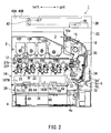
- FIG. 2 is a cross sectional view showing an internal configuration of the image forming device 1. The configuration of the image forming device 1 will be described with reference to FIGS. 1 and 2 .
- a full color copier is illustrated as the image forming device 1. It is noted that in order to clarify the directional relationship, the directions of the image forming device 1 in the drawings are indicated with reference to the position where a user stands when using it. Accordingly, description of the image forming device 1 will be made below with reference to this direction.
- the image forming device 1 includes a device body 2.
- the device body 2 has a hollow box structure in substantially rectangular parallelepiped shape to form inside space (inside exit unit 3).
- the device body 2 is configured to form an image on a sheet.
- the device body 2 includes a lower box body 2A in substantially rectangular parallelepiped shape, an upper box body 2B in substantially rectangular parallelepiped shape provided above the lower box body 2A, and a joint box body 2C that joins the lower box body 2A and the upper box body 2B together. Further, the inside space surrounded by the lower box body 2A, the upper box body 2B, and the joint box body 2C defines the inside exit unit 3 capable of accommodating a sheet after image formation. The sheet after image formation is fed from an exit port 19a (see FIG. 2 ) to the inside exit unit 3 and is then stacked on the upper part of the lower box body 2A.
- a paper feed cassette 4 configured to accommodate a sheet, on which an image is to be formed, is fitted in the lower box body 2A.
- the paper feed cassette 4 is capable of being drawn in front from the front of the lower box body 2A.
- the paper feed cassette 4 is a cassette provided for automatic paper supply.
- a multi tray unit 5 is fitted to the right side surface of the device body 2.
- the multi tray unit 5 includes a paper feed tray 5a on which a sheet is manually placed and a paper feed unit 5b configured to convey the manually placed sheet to an image forming section 14 (see FIG. 2 ) in the lower box body 2A.
- the paper feed tray 5a is mounted at the lower box body 2A in an openable and closable manner and is closed in a non-use state. In a use state, the paper feed tray 5a is opened so that a sheet is placed on the paper feed tray 5a.
- An operation panel unit 6 is provided in front of the upper box body 2B.
- the operation panel unit 6 includes an LCD touch panel 6a, a numeric keypad, a start key, etc. and receives inputs of various types of operation instructions from the user. The user can input the number of to-be-printed sheets, print density, etc. through the operation panel unit 6.
- an automatic document feeder (ADF) 7 (not shown in FIG. 2 ) is mounted which is configured to automatically feed an original document to a predetermined document reading position (a first contact glass 40A).
- the ADF 7 is mounted on the upper box body 2B so that the rear end edge of the ADF 7 is rotatable about the upper box body 2B.
- the ADF 7 includes a document feed tray 7a on which an original document is placed, a conveyance section 7b configured to convey the original document via a document reading position, and a document exit tray 7c to which the read original document is fed.
- the lower box body 2A accommodates therein a toner container group (a toner container 10Y, a toner container 10M, a toner container 10C, and a toner container 10Bk), an intermediate transfer unit 12, the image forming section 14, an exposure unit 16YM, an exposure unit 16CB, and the paper feed cassette 4 in this order from above.
- a toner container group a toner container 10Y, a toner container 10M, a toner container 10C, and a toner container 10Bk
- an intermediate transfer unit 12 the image forming section 14
- an exposure unit 16YM an exposure unit 16CB
- the paper feed cassette 4 in this order from above.
- each of the exposure unit 16YM and the exposure unit 16CB may be referred to as an exposure device in the present specification.
- the image forming section 14 includes, in order to form a full color toner image, four image forming units (an image forming unit 20Y, an image forming unit 20M, an image forming unit 20C, and an image forming unit 20Bk).
- the image forming unit 20Y forms a yellow (Y) toner image.
- the image forming unit 20M forms a magenta (M) toner image.
- the image forming unit 20C forms a cyan (C) toner image.
- the image forming unit 20Bk forms a black (Bk) toner image.
- Each of the image forming unit 20Y, the image forming unit 20M, the image forming unit 20C, and the image forming unit 20Bk includes a photosensitive drum 21, a charger 22, a developing unit 23, a primary transfer roller 24, and a cleaning unit 25.
- the charger 22, the developing unit 23, the primary transfer roller 24, and the cleaning unit 25 are arranged around the photosensitive drum 21.
- the photosensitive drum 21 rotates about the axis of itself to form an electrostatic latent image and a toner image on the peripheral surface of itself.
- a photosensitive drum made of amorphous silicon (a-Si) based material may be used.
- the charger 22 is configured to electrostatically charge the surface of the photosensitive drum 21 uniformly.
- the electrostatically charged peripheral surface of the photosensitive drum 21 is exposed by the exposure unit 16YM or the exposure unit 16CB so that an electrostatic latent image is formed on the peripheral surface of the photosensitive drum 21.
- the developing unit 23 supplies toner to the peripheral surface of the photosensitive drum 21 in order to develop the electrostatic latent image formed on the photosensitive drum 21.
- the developing unit 23 is for a two-component developer, for example.
- the developing unit 23 includes therein a stirring roller, a magnetic roller, a developing roller, etc.
- the primary transfer roller 24 is configured to primarily transfer the toner image on the photosensitive drum 21 onto an intermediate transfer belt 26.
- the intermediate transfer belt 26 is provided in the intermediate transfer unit 12.
- the primary transfer roller 24 and the photosensitive drum 21 interpose the intermediate transfer belt 26 to form a nip.
- the cleaning unit 25 cleans the peripheral surface of the photosensitive drum 21 after transfer of the toner image.
- the yellow toner container 10Y, the magenta toner container 10M, the cyan toner container 10C, and the black toner container 10Bk of the toner container group each store toner of corresponding color.
- the toner in the respective colors is supplied to the respective developing units 23 of the image forming unit 20Y, the image forming unit 20M, the image forming unit 20C, and the image forming unit 20Bk through respective supply paths (not shown in the drawings).
- the exposure unit 16YM forms an electrostatic latent image based on image data of a document image onto the peripheral surface of each photosensitive drum 21 of the image forming unit 20Y and the image forming unit 20M.
- the exposure unit 16CB forms an electrostatic latent image based on the image data of the document image onto the peripheral surface of each photosensitive drum 21 of the image forming unit 20C and the image forming unit 20Bk.
- the configurations of the exposure unit 16YM and the exposure unit 16CB will be described later.
- the intermediate transfer unit 12 includes the intermediate transfer belt 26, a drive roller 27a, and a driven roller 27b. Toner images of the photosensitive drums 21 of the image forming unit 20Y, the image forming unit 20M, the image forming unit 20C, and the image forming unit 20Bk are each transferred onto the intermediate transfer belt 26 (primary transfer). The toner images transferred from the respective photosensitive drums 21 and overlaid one on top of the other are transferred to a sheet supplied from the paper feed cassette 4 or the paper feed tray 5a in a secondary transfer section 30 (secondary transfer).
- the paper feed cassette 4 accommodates a sheaf of a plurality of stacked sheets.
- a pickup roller 4a is disposed on the upper right side of the paper feed cassette 4.
- Driving the pickup roller 4a allows the sheets in the paper feed cassette 4 to be fed one by one from the uppermost sheet of the sheaf. Then, the sheets are conveyed to a carry-in path 32.
- driving the paper feed roller 5c of the paper feed unit 5b allows a sheet placed on the paper feed tray 5a to be conveyed to the carry-in path 32.
- a sheet conveyance path 34 is provided which extends to the exit port 19a via the secondary transfer section 30, a fixing unit 18, and a paper exit unit 19.
- a paper stop roller pair 33 is disposed on the upstream side of the secondary transfer section 30 in the sheet conveyance path 34. The sheet is once stopped at the paper stop roller pair 33 to be subjected to skew correction and then is sent to the secondary transfer section 30 at predetermined timing for image transfer.
- the fixing unit 18 and the paper exit unit 19 are accommodated inside the joint box body 2C.
- the fixing unit 18 includes a fixing roller and a pressure roller.
- the secondary transfer section 30 heats and pressurizes the sheet, to which the toner images are secondary transferred, to fix the toner images to the sheet.
- the paper exit unit 19 arranged on the downstream side of the fixing unit 18 feeds the sheet with the color images subjected to fixing treatment from the exit port 19a toward the inside exit unit 3.
- the first contact glass 40A and a second contact glass 40B are fitted in the upper surface of the upper box body 2B.
- the first contact glass 40A is provided to read an original document sheet automatically fed from the ADF 7.
- the second contact glass 40B is provided to read a manually placed original document sheet.
- the upper box body 2B accommodates therein an image sensor 44 and a scanning mechanism 42 configured to optically read document information.
- the scanning mechanism 42 includes a light source, a moving carriage, a reflecting mirror, etc. and brings reflected light from an original document to the image sensor 44.
- the image sensor 44 is configured to perform photoelectric conversion of the reflected light to an analog electrical signal.
- the analog electrical signal is converted to a digital electrical signal in an A/D conversion circuit (not shown in the drawings) and is then input to the exposure unit 16YM and the exposure unit 16CB.
- the configurations of the exposure unit 16YM and the exposure unit 16CB will be described next with reference to FIGS. 2-6 .
- the exposure unit 16YM is arranged across the image forming unit 20Y and the image forming unit 20M below the image forming unit 20Y and the image forming unit 20M.
- the exposure unit 16CB is arranged across the image forming unit 20C and the image forming unit 20Bk below the image forming unit 20C and the image forming unit 20Bk.
- FIG. 3 is an explanatory diagram schematically showing the main components of the exposure unit 16YM.
- the exposure unit 16YM exposes a photoreceptor of an image forming device that includes the photoreceptor and an air flow generator configured to generate an air flow.
- the exposure unit 16YM includes a laser light source 50, a collimating lens 52, a cylindrical lens 54, a polygon mirror (rotary polygon mirror) 56, a polygon motor 58, an f ⁇ lens 60, and a reflecting mirror 62.
- the laser light source 50 is formed of a semiconductor laser oscillator of a diode laser or the like.
- the laser light source 50 outputs, along a predetermined optical axis, laser light (exposure light) of which light amount is adjusted according to analog voltage for control output from a control section (not shown in the drawings).
- the collimating lens 52 is arranged in the vicinity of the laser light source 50 and is configured to adjust the beam diameter of the laser light output from the laser light source 50.
- the cylindrical lens 54 is configured to further adjust the beam diameter of the laser light transmitted through the collimating lens 52.
- the polygon mirror 56 is driven and rotated at a predetermined speed by the polygon motor 58 to deflect the laser light so that the laser light output from the cylindrical lens 54 scans the photosensitive drum 21 in the longitudinal direction (main scanning direction) of the photosensitive drum 21 (photoreceptor: 20Y).
- the f ⁇ lens 60 brings the laser light to the reflecting mirror 62 so that the laser light scans the photosensitive drum 21 at a predetermined speed in the main scanning direction of the photosensitive drum 21.
- the reflecting mirror 62 reflects the laser light output from the f ⁇ lens 60 and brings it to the photosensitive drum 21.
- the exposure unit 16YM further includes, besides the f ⁇ lens 60 and the reflecting mirror 62, an f ⁇ lens and a reflecting mirror (not shown in the drawings) to lead the laser light onto the photosensitive drum 21 of the image forming unit 20M.
- the exposure unit 16YM performs scan while emitting a laser light beam to the respective photosensitive drums 21 of the image forming unit 20Y and the image forming unit 20M, thereby forming an electrostatic latent image on each photosensitive drum 21.
- the exposure unit 16CB has the same configuration as the exposure unit 16YM except that the laser light beam is emitted to the respective photosensitive drums 21 of the image forming unit 20C and the image forming unit 20Bk.
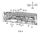
- Each of the exposure unit 16YM and the exposure unit 16CB further includes a box-shaped (substantially rectangular parallelepiped shaped) casing 64 flat in the vertical direction. All of the members, such as the laser light source 50, etc. are accommodated in the casing 64. It is noted that the polygon motor 58 is boarded on a control substrate 70, as shown in FIG. 4 , and is fixed integrally with the control substrate 70 at the inner bottom of the casing 64.
- control substrate 70 includes a substrate main body 70a with a circuit on the substrate, the polygon motor 58 boarded on the substrate main body 70a, the polygon mirror 56 fitted to an output shaft 58a of the polygon motor 58, electronic components for controlling driving of the polygon motor 58, such as a driver IC 59, etc., and a heat sink 72 configured to dissipate heat generated at the polygon motor 58 and the driver IC 59 (each corresponds to heat sources in the present disclosure).
- the control substrate 70 is fixed to the casing 64 in such a fashion that the polygon motor 58 and the driver IC 59 are arrayed in the back and forth direction, specifically, so that the polygon motor 58 is located behind the driver IC 59.
- the heat sink 72 is fixed across a region of the lower surface of the substrate main body 70a where the polygon motor 58 and the driver IC 59 are boarded.
- FIG. 4 is a cross sectional view taken along the lines IV-IV in FIG. 2 .
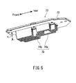
- the heat sink 72 includes, as shown in FIGS. 4 and 5 , a plate-shaped base 73 long and narrow in the back and forth direction and a plurality of fins 74 each suspended from the base 73 and arrayed in parallel to each other in the transverse direction.
- the heat sink 72 is incorporated in the control substrate 70 in such a manner that the base 73 is fixed to the lower surface of the substrate main body 70a by means of a bolt or the like.
- the base 73 and the fins 74 are integrally formed of a metal material having high thermal conductivity, such as aluminum or copper. In this example, the heat sink 72 is formed by aluminum die casting.
- the heat sink 72 is incorporated in the control substrate 70 so as to be in contact with the polygon motor 58 and the driver IC 59.
- a through hole 73a is formed in each of the substrate main body 70a and the heat sink 72 so as to pass through the substrate main body 70a and the heat sink 72 in their thickness directions.
- the polygon motor 58 is fixed to the substrate main body 70a with it inserted in the through holes 73a, etc. so that the bearing portion 58b of the polygon motor 58 (bearing portion of the output shaft 58a) is in contact with at least the inner peripheral surface of the through hole 73a of the heat sink 72.
- a protrusion 73b is formed at a position frontward of the through holes 73a on the upper surfaced of the base 73 of the heat sink 72.
- the protrusion 73b protrudes from the upper surface of the substrate main body 70a through a through hole (through hole formed at a position adjacent to the position where the driver IC 59 is to be mounted) formed in the substrate main body 70a.
- the driver IC 59 is boarded (mounted) on the substrate main body 70a so as to be in contact with the protrusion 73b. In this way, thermal conduction from the polygon motor 58 and the driver IC 59 to the heat sink 72 can be achieved through each contact of the polygon motor 58 and the driver IC 59 with the heat sink 72.
- the plurality of fins 74 of the heat sink 72 are formed so as to increase in height h from the rear side toward the front side, as shown in FIGS. 4 and 5 .
- each fin 74 is formed stepwise as a whole so that the height in a region 74b on the front side from around the middle point in the back and forth direction (hereinafter referred to as a front region 74b) is a predetermined height higher than that of a region 74a on the rear side from around the middle point in the back and forth direction (hereinafter referred to as a rear region 74a).
- the polygon motor 58 is in contact with the heat sink 72 (the base 73) at its part corresponding to the rear region 74a of each fin 74.
- the driver IC 59 is in contact with the heat sink 72 (the base 73) at its part corresponding to the front region 74b of each fin 74.
- each fin 74 may be referred to as a first region and a second region, respectively.
- the polygon motor 58 and the driver IC 59 may be referred to as a first heat source and a second heat source, respectively. It is noted that the height of the fins 74 is the same entirely across the rear regions 74a. Similarly, it is the same entirely across the front regions 74b.
- the fins 74 protrude below the exposure unit 16YM and the exposure unit 16CB from each casing 64 through an opening 67 formed at each bottom of the casings 64.
- recesses 66 which are recessed upward and extend in the back and forth direction, are formed at respective parts, to which the control substrate 70 is fixed, of the bottom surface of the casing 64 of the exposure unit 16CB and the bottom surface of the casing 64 of the exposure unit 16YM, as shown in FIG. 2 .
- the fins 74 protrude from the recesses 66 through each opening 67 formed in the inner bottoms of the recesses 66.
- each recess 66 of the casings 64 and a frame member 36 of the lower box body 2A form a wind path (cooling wind path 80) for cooling the exposure unit 16YM or the exposure unit 16CB in the image forming device 1.
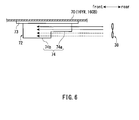
- An air blowing fan 38 (schematically shown in FIG. 6 ) fitted at the rear part of the lower box body 2A takes and sends the outside air into the cooling wind path 80 to generate an air flow flowing from the rear side toward the front side inside the cooling wind path 80. That is, the fins 74 of the heat sink 72 are disposed inside the cooling wind path 80 so as to extend in the direction parallel to the direction where the air flow flows and so as to be arrayed in the direction orthogonal to the direction where the air flow flows. It is noted that the air blowing fan 38 may be referred to as an air flow generator in the present specification.
- the heat of each of the exposure unit 16YM and the exposure unit 16CB (i.e., heat generated at each polygon motor 58 and each driver IC 59) is dissipated through the heat sink 72.
- the fins 74 are arranged inside the cooling wind path 80 to allow the air to flow among the fins 74, thereby promoting heat transfer (heat dissipation) from the heat sink 72 to the flowing air.
- the heat can be favorably dissipated from the exposure unit 16YM and the exposure unit 16CB.
- the heat sink 72 has the configuration in which the fins 74 increase in height h from the rear side toward the front side (from upstream side toward the downstream side in the direction where the air flow flows), which can results in efficient heat dissipation from the heat sink 72.
- the height of the fins 74 of the heat sink 72 is the same in the entire region in the back and forth direction, the temperature of the air increases in the course of air flowing in the fins 74.
- the heat dissipation effect is reduced dominantly in the front regions of the fins 74 (regions on the downstream side in the direction where the air flow flows) compared with in the rear regions thereof.
- the air at comparatively low temperature i.e., air of which temperature is comparatively low because it does not flow through the rear regions 74a; indicated by the broken arrows in FIG. 6
- the air at comparatively low temperature flows in a given region including the tip ends of the fins 74 in the front regions 74b of the fins 74, as schematically shown in FIG. 6 .
- a phenomenon that the heat dissipation effect reduces in the front regions 74b of the fins 74 can be prevented, thereby enhancing the heat dissipation effect in the heat sink 72 as a whole.
- the heat sink 72 which is comparatively small in size, can efficiently dissipate the heat of the exposure unit 16YM and the exposure unit 16CB (each polygon motor 58 and each driver IC 59). In other words, it is unnecessary to provide a large heat sink for each of the exposure unit 16YM or the exposure unit 16CB (each control substrate 70) and to provide a large air blow fan, while the heat dissipation effect of the exposure unit 16YM and the exposure unit 16CB can be enhanced.
- the image forming device 1 illustrates one example of the image forming device of the present disclosure, and its specific configuration can be appropriately modified within the scope not deviated from the subject matter of the present disclosure.
- the heat sink 72 boarded on the control substrate 70 may include a partition plate 75, as shown in FIG. 7 .
- the partition plate 75 partitions the air flow flowing along the fins 74 at a predetermined position in the height direction (vertical direction) of the fins 74.
- the partition plate 75 is connected to the tip ends of the fins 74 over the rear regions 74a of the fins 74.
- the air can stably flow along the partition plate 75 to be prevented from flowing turbulently in the height direction of the fins 74. Accordingly, the air at comparatively low temperature flowing in the region including the fin tip ends in the front regions 74b (air not flowing through the rear regions 74a; indicated by the broken arrow in the drawing) can flow more reliably.
- the partition plate 75 is made of aluminum or copper having high thermal conductivity, similarly to the base 73 and the fins 74. In this case, in view of producibility, it is suitable that the base 73, the fins 74, and the partition plate 75 of the heat sink 72 are integrally formed by aluminum die casting or the like.
- the shape of the fins 74 are not limited to the shape in which their height increases by only one step in the middle in the back and forth direction, as shown in FIG. 5 , and may have a shape in which their height successively increases in steps of two or more.
- the partition plate 75 (see FIG. 7 ) may be provided in each of regions of the fins 74 with different heights to partition the path of the air flow along the height direction of the fins 74.
- each rear region 74a may be a region in which the height of the fins 74 linearly changes (increases) (height increasing region).
- the fins 74 may each have a region in which the height h of the fins 74 linearly changes (increases) over the entire region of the fins 74 (height increasing region).
- the fins 74 may have a region in which their height linearly changes (increases) between the rear region 74a and the front region 74b of the fin 74 (height increasing region).
- the heat sink 72 with the fins 74 having such a height increasing region can also exert operation and effects equivalent to these of the hat sink 72 shown in FIG. 5 and the like.
- the fins 74 can be increased in height from the upstream side toward the downstream side in the direction where the air flow flows, while the heat dissipation area of the fins 74 can be secured largely.
- each heat sink 72 as shown in FIGS. 8 and 9 may also include the partition plate 75 (see FIG. 7 ). In the case with the heat sink 72 shown in FIG. 8 , for example, a slit extending horizontally from the rear end part of each fin 74 may be formed at a specific height of each fin 74, and the partition plate 75 may be inserted therein to be fixed.
- the air flow flowing from the rear side toward the front side inside the cooling wind path 80 is formed by sending the outside air into the cooling wind path 80 by the air blowing fan 38 provided in the lower box body 2A in the image forming device 1 according to the present embodiment.
- an exhaust fan may be provided to exhaust the air inside the cooling wind path 80. This can generate the air flow flowing from the rear side toward the front side inside the cooling wind path 80.
- the image forming device may be a printer, a facsimile machine, an image forming device that forms a monochrome image, or a multifunction device having functions thereof.
Landscapes
- Physics & Mathematics (AREA)
- General Physics & Mathematics (AREA)
- Life Sciences & Earth Sciences (AREA)
- Engineering & Computer Science (AREA)
- Atmospheric Sciences (AREA)
- Biodiversity & Conservation Biology (AREA)
- Ecology (AREA)
- Environmental & Geological Engineering (AREA)
- Environmental Sciences (AREA)
- Electrophotography Configuration And Component (AREA)
- Control Or Security For Electrophotography (AREA)
- Laser Beam Printer (AREA)
- Mechanical Optical Scanning Systems (AREA)
- Light Sources And Details Of Projection-Printing Devices (AREA)
Applications Claiming Priority (1)
| Application Number | Priority Date | Filing Date | Title |
|---|---|---|---|
| JP2012066930A JP2013198993A (ja) | 2012-03-23 | 2012-03-23 | 画像形成装置および露光装置 |
Publications (2)
| Publication Number | Publication Date |
|---|---|
| EP2642352A2 true EP2642352A2 (de) | 2013-09-25 |
| EP2642352A3 EP2642352A3 (de) | 2016-12-28 |
Family
ID=47843026
Family Applications (1)
| Application Number | Title | Priority Date | Filing Date |
|---|---|---|---|
| EP13153202.0A Withdrawn EP2642352A3 (de) | 2012-03-23 | 2013-01-30 | Bilderzeugungsvorrichtung |
Country Status (4)
| Country | Link |
|---|---|
| US (1) | US8842148B2 (de) |
| EP (1) | EP2642352A3 (de) |
| JP (1) | JP2013198993A (de) |
| CN (1) | CN103324058B (de) |
Families Citing this family (4)
| Publication number | Priority date | Publication date | Assignee | Title |
|---|---|---|---|---|
| CN104623896A (zh) * | 2015-03-03 | 2015-05-20 | 成都龙腾中远信息技术有限公司 | 一种家用体感游戏机使用的图像增益装置 |
| CN108566760A (zh) * | 2018-01-16 | 2018-09-21 | 东莞市远鑫电子科技有限公司 | 不规则状散热器及其生产工艺 |
| US11753267B2 (en) | 2019-04-29 | 2023-09-12 | Hewlett-Packard Development Company, L.P. | Output tray fins |
| CN110967956A (zh) * | 2019-12-16 | 2020-04-07 | 芜湖英罗智能制造有限公司 | 一种激光打印用激光器热量回收利用装置 |
Family Cites Families (17)
| Publication number | Priority date | Publication date | Assignee | Title |
|---|---|---|---|---|
| JPH07249885A (ja) * | 1994-03-10 | 1995-09-26 | Nemitsuku Ramuda Kk | 冷却構造 |
| JPH10206776A (ja) * | 1997-01-23 | 1998-08-07 | Fuji Xerox Co Ltd | 光走査装置 |
| US6172786B1 (en) * | 1997-09-03 | 2001-01-09 | Konica Corporation | Optical deflection device and image forming apparatus therewith |
| JP3550008B2 (ja) | 1997-11-30 | 2004-08-04 | 株式会社リコー | 光ビーム走査装置 |
| US6195190B1 (en) * | 1998-05-20 | 2001-02-27 | Minolta Co., Ltd. | Optical beam scanning device |
| JP3597410B2 (ja) * | 1999-03-12 | 2004-12-08 | シャープ株式会社 | 電子機器の冷却装置 |
| JP2001004945A (ja) * | 1999-06-17 | 2001-01-12 | Canon Inc | 走査式光学装置の放熱構造 |
| JP2002261477A (ja) * | 2001-02-28 | 2002-09-13 | Meidensha Corp | プリント板モジュール |
| JP2003043394A (ja) * | 2001-07-30 | 2003-02-13 | Konica Corp | 走査光学装置及び画像形成装置 |
| JP2004262117A (ja) * | 2003-03-03 | 2004-09-24 | Konica Minolta Holdings Inc | 画像形成装置及びその製造方法 |
| US7326861B2 (en) * | 2005-01-19 | 2008-02-05 | Kabushiki Kaisha Toshiba | Shielding cover having cooling fin and optical scanning device |
| JP5370798B2 (ja) * | 2006-07-31 | 2013-12-18 | 株式会社リコー | 光走査装置および光走査装置を備えた画像形成装置 |
| JP2008140802A (ja) * | 2006-11-30 | 2008-06-19 | Fuji Electric Fa Components & Systems Co Ltd | ヒートシンク |
| JP2008235387A (ja) * | 2007-03-19 | 2008-10-02 | Shindengen Electric Mfg Co Ltd | 放熱構造を備えた電気電子機器装置 |
| JP5272523B2 (ja) * | 2008-06-03 | 2013-08-28 | 株式会社リコー | 画像形成装置 |
| CN102081231B (zh) * | 2009-11-30 | 2014-11-19 | 京瓷办公信息系统株式会社 | 光扫描装置以及图像形成装置 |
| US8325480B2 (en) * | 2010-05-20 | 2012-12-04 | International Business Machines Corporation | Heat sink for distributing a thermal load |
-
2012
- 2012-03-23 JP JP2012066930A patent/JP2013198993A/ja active Pending
-
2013
- 2013-01-30 EP EP13153202.0A patent/EP2642352A3/de not_active Withdrawn
- 2013-01-30 US US13/754,418 patent/US8842148B2/en not_active Expired - Fee Related
- 2013-03-14 CN CN201310080956.2A patent/CN103324058B/zh not_active Expired - Fee Related
Non-Patent Citations (1)
| Title |
|---|
| None |
Also Published As
| Publication number | Publication date |
|---|---|
| US8842148B2 (en) | 2014-09-23 |
| CN103324058A (zh) | 2013-09-25 |
| CN103324058B (zh) | 2016-01-27 |
| US20130250028A1 (en) | 2013-09-26 |
| JP2013198993A (ja) | 2013-10-03 |
| EP2642352A3 (de) | 2016-12-28 |
Similar Documents
| Publication | Publication Date | Title |
|---|---|---|
| CN102081231B (zh) | 光扫描装置以及图像形成装置 | |
| US8842148B2 (en) | Image forming device with fins having increasing height | |
| CN101655604B (zh) | 图像形成装置的光扫描装置 | |
| JP5201055B2 (ja) | 画像形成装置 | |
| US8493427B2 (en) | Optical scanning apparatus and image forming apparatus provided with the same | |
| US10425550B2 (en) | Optical scanning device with duct for heat dissipation, and image forming device having the same | |
| JP5988039B2 (ja) | 光源ユニット、走査光学装置、及び画像形成装置 | |
| JP5843096B2 (ja) | 画像形成装置 | |
| JP5580275B2 (ja) | レンズアレイ及びこれを用いた画像形成装置 | |
| JP6460345B2 (ja) | 光走査装置 | |
| JP5255795B2 (ja) | 画像形成装置 | |
| JP2010049042A (ja) | 画像形成装置 | |
| JP5413722B2 (ja) | 画像形成装置 | |
| JP5297597B2 (ja) | 走査光学装置及びこれを搭載した画像形成装置 | |
| JP2015200852A (ja) | 光走査装置及び該光走査装置を備えた画像形成装置 | |
| US9304471B2 (en) | Image forming apparatus, discharge tray used in image forming apparatus | |
| JP2019209586A (ja) | 露光装置および画像形成装置 | |
| JP2011137941A (ja) | 光走査装置及び画像形成装置 | |
| JP5265607B2 (ja) | 光走査装置及び光走査装置が組み込まれた画像形成装置 | |
| JP2006003503A (ja) | 画像形成装置 | |
| JP5145378B2 (ja) | 走査光学装置及びこれを搭載した画像形成装置 | |
| CN108885338A (zh) | 光扫描装置及具有该光扫描装置的图像形成装置 | |
| JP6465312B2 (ja) | 光走査装置に搭載される光源駆動回路基板、及び光走査装置 | |
| JP6164577B2 (ja) | 発光装置 | |
| JP5016365B2 (ja) | 走査光学装置及びこれを搭載した画像形成装置 |
Legal Events
| Date | Code | Title | Description |
|---|---|---|---|
| PUAI | Public reference made under article 153(3) epc to a published international application that has entered the european phase |
Free format text: ORIGINAL CODE: 0009012 |
|
| AK | Designated contracting states |
Kind code of ref document: A2 Designated state(s): AL AT BE BG CH CY CZ DE DK EE ES FI FR GB GR HR HU IE IS IT LI LT LU LV MC MK MT NL NO PL PT RO RS SE SI SK SM TR |
|
| AX | Request for extension of the european patent |
Extension state: BA ME |
|
| PUAL | Search report despatched |
Free format text: ORIGINAL CODE: 0009013 |
|
| AK | Designated contracting states |
Kind code of ref document: A3 Designated state(s): AL AT BE BG CH CY CZ DE DK EE ES FI FR GB GR HR HU IE IS IT LI LT LU LV MC MK MT NL NO PL PT RO RS SE SI SK SM TR |
|
| AX | Request for extension of the european patent |
Extension state: BA ME |
|
| RIC1 | Information provided on ipc code assigned before grant |
Ipc: G03G 21/20 20060101ALI20161121BHEP Ipc: G03G 21/16 20060101AFI20161121BHEP |
|
| STAA | Information on the status of an ep patent application or granted ep patent |
Free format text: STATUS: THE APPLICATION IS DEEMED TO BE WITHDRAWN |
|
| 18D | Application deemed to be withdrawn |
Effective date: 20170629 |