EP2640530B1 - Industrielle reinigungsanlage - Google Patents
Industrielle reinigungsanlage Download PDFInfo
- Publication number
- EP2640530B1 EP2640530B1 EP11813774.4A EP11813774A EP2640530B1 EP 2640530 B1 EP2640530 B1 EP 2640530B1 EP 11813774 A EP11813774 A EP 11813774A EP 2640530 B1 EP2640530 B1 EP 2640530B1
- Authority
- EP
- European Patent Office
- Prior art keywords
- cover
- lifting arm
- plant according
- cleaning
- cleaning chamber
- Prior art date
- Legal status (The legal status is an assumption and is not a legal conclusion. Google has not performed a legal analysis and makes no representation as to the accuracy of the status listed.)
- Active
Links
Images


Classifications
-
- B—PERFORMING OPERATIONS; TRANSPORTING
- B08—CLEANING
- B08B—CLEANING IN GENERAL; PREVENTION OF FOULING IN GENERAL
- B08B3/00—Cleaning by methods involving the use or presence of liquid or steam
- B08B3/02—Cleaning by the force of jets or sprays
-
- B—PERFORMING OPERATIONS; TRANSPORTING
- B08—CLEANING
- B08B—CLEANING IN GENERAL; PREVENTION OF FOULING IN GENERAL
- B08B15/00—Preventing escape of dirt or fumes from the area where they are produced; Collecting or removing dirt or fumes from that area
- B08B15/02—Preventing escape of dirt or fumes from the area where they are produced; Collecting or removing dirt or fumes from that area using chambers or hoods covering the area
-
- B—PERFORMING OPERATIONS; TRANSPORTING
- B08—CLEANING
- B08B—CLEANING IN GENERAL; PREVENTION OF FOULING IN GENERAL
- B08B3/00—Cleaning by methods involving the use or presence of liquid or steam
- B08B3/04—Cleaning involving contact with liquid
Definitions
- the invention relates to an industrial cleaning system with one or more cleaning chambers for treating items to be cleaned, and a mobile, rotatable or pivotable transport device for loading or unloading, wherein the transport device has a lifting device with a gripping tool for the cleaning, and the lifting device with the gripping tool is guided through openings of the cleaning chambers, which can be closed with a lid.
- a device for the partial irradiation of cleaning material which is part of a cleaning system, are washed with the workpieces, rinsed or dried.
- the device for radiation consists of several arranged around a pedestal around jet chambers with a projecting jet pipe.
- the jet chambers have a hood, which is mounted with the aid of a guide horizontally displaceable in the direction of the base.
- the base In relation to the hood, the base is installed stationary and has according to the number of hoods lid for tight closure in the working position.
- the hood is separated from the lid and stationed away from the lid. From the level of the lid protrudes a claw-like acting gripping tool out of the base.
- the gripping tool is rotatably mounted and pivotable by means of a drive on the base, so that the workpiece for the purpose of radiation of several sides to the jet pipe can be aligned.
- hoods and covers are pairwise associated with each other, so that each hood can be closed with a separate lid to avoid detergent losses in a horizontal design.
- the variability in the mobility of the gripping tool is limited in the known device. Through this Restrictions, the treatment of the cleaning material is not optimal on all peripheral sides, whereby the treatment duration is extended.
- a cleaning system comprising two movable in a circle cleaning chambers with receptacles for the items to be cleaned and a stationary, located above the movement path lid device with fixed treatment fittings.
- the lid device is lowered in the working position on a, located in position cleaning chamber and shoots the cleaning chamber.
- the cover device can be moved with a lifting device from an open position to a closed position. For an up and down movement of the lifting device during treatment, the system is not designed in principle.
- the cleaning chamber has a housing for laundry, which hangs on a lid, which in turn hangs on a lifting device which is movable on a rail between a working position and a loading station.
- a lifting device which is movable on a rail between a working position and a loading station.
- the lid is raised with the laundry and moved into the loading position and lowered into the cleaning chamber until the lid rests on the walls of the cleaning chamber and seals.
- the laundry can be rotated during the washing process or pivoted back and forth.
- the known device has only a cleaning chamber and the lifting device can not be operated during the treatment, because otherwise the lid is opened and treatment medium is lost. Furthermore, an adjustment of the cleaning material within the cleaning chamber is not possible with the lifting device.
- the rotation or reciprocation of the cleaning material is carried out in a conventional manner by means of a separate drive and not with the lifting device.
- the object of the invention is to achieve an improvement of the cleaning system in such a way by the closure of the Cleaning chamber is carried by a lid device which is adapted to the direction of movement of the lifting device.
- the object is achieved according to the invention a first embodiment by the measures listed in claim 1 and according to a second embodiment by the measures listed in claim 2. Further developments of the invention are described in the subclaims.
- the advantage of the invention is that the lid remains on the lifting arm of the lifting device when the transport of cleaning material from the cleaning chamber for storage or in a multi-chamber system from one cleaning chamber to the next.
- lifting arm and cover form a structural unit, entrainment of the lid during transport of the cleaning material with the transport device takes place.
- the special feature of this is that the lifting arm receives the lid in a central opening and the lid is movably guided on the lifting arm in the longitudinal direction, so that a lifting movement of the items to be cleaned is possible with the cleaning chamber closed.
- the lifting arm has a driver for the lid, so that by lifting the lifting arm from a defined lifting height entrainment takes place.
- the cleaning chamber is always closed during an up and down movement of the cleaning material in the cleaning chamber by lifting and lowering the lift arm during treatment. Furthermore, the cleaning chamber is automatically opened by lifting the lifting arm for the purpose of unloading the cleaning material.
- the driver of the lifting arm comes with the lid in contact connection.
- Another advantage of the invention is that the cleaning material can be adjusted in the cleaning chamber with the lid closed by the lifting arm in relation to the cleaning chamber in height is adjustable. This cleaning material of different sizes can be positioned exactly on radiation units of the cleaning chamber.
- the alignment of the gripping tool can be carried out exactly to the installations in the cleaning chamber, with which treatment medium is sprayed, sprayed or blasted onto the items to be cleaned. Furthermore, during the treatment by reciprocating or moving up and down moving the cleaning material to achieve an improvement of the treatment result, because the cleaning material can be performed on nozzle sticks along to treat critical areas on the periphery of the cleaning material intensive.
- the lift arm In the closed position of the lid, the lift arm can perform a vertical up and down movement and a horizontal back and forth movement.
- the lid is slidably guided on a support, preferably on the end wall of the cleaning chamber, and can be moved by horizontal movement of the lifting arm within certain limits.
- the lifting arm of the lifting device is advantageously designed as a column arranged vertically in guides and can be moved with a chain drive.
- the drive chain is guided between two pinions, wherein a pinion is driven by a motor.
- the chain drive is attached to a console, which is attached to a trolley.
- the trolley moves on guide rails and can transport the lifting arm of the lifting device from a position above the tray for the cleaning to a position above the cleaning chamber.
- With the lifting arm can also be carried out a vertical movement up and down in the cleaning chamber.
- the gripping tool the items to be cleaned can be picked up by a tray and lifted and lowered into the cleaning chamber.
- a reciprocating motion can be performed so that the cleaning material can be performed at any desired location on the spray spray or jet nozzles during the treatment along.
- the lid makes these movements with and closes the opening.
- the lifting arm of Lifting device can also be controlled within the cleaning chamber and during the treatment in the vertical direction up and down, so that all points of the laundry can be reached on one side.
- the lifting arm is rotatably mounted with the gripping tool about its longitudinal axis, so that cleaning can be carried out by rotation of the gripping tool on all peripheral sides.
- a continuous drive shaft for the gripping tool is mounted in the lifting arm, which is driven by a mounted on the other end of the lifting arm motor.
- the lifting device has a lifting arm with gripping tool, so that dirty laundry can be removed from the tray and placed in a first cleaning chamber in which a first treatment process, such as a washing process takes place, into a final cleaning chamber in which, for example, a drying process takes place and there is provided from the cleaned laundry in the tray for removal.
- Rails are advantageously mounted on the trolley transversely to the direction in which a carriage is guided. The carriage can carry the lifting device, and the lifting arm with the gripping tool can thereby be moved independently of the running direction of the trolley.
- the transport device has a multi-unit, controllable about axes manipulator arm and a lifting arm with a gripping tool.
- the lid is movably guided in a central opening along the shank of the lifting arm, and there is a connection between the lid and the lifting arm via a self-aligning bearing.
- the pendulum bearing is advantageously a ball joint, which additionally has an axial guide for receiving the lifting arm.
- the ball joint is advantageously formed with a ball head on the lifting arm and a spherical shell on the cover in the region of the central opening.
- the ball shell advantageously encloses the ball head beyond its diameter, resulting in a simple connection. Furthermore, by this training, a seal against over the lid.
- a driver for the lid is provided, wherein for the purpose of entrainment of the lid in upward movement of the lifting arm of the driver forms a stop for the lid.
- the self-aligning bearing is equipped with an inserted with play in the central opening of the lid elongated guide body.
- the mobility of the guide body is defined in the central opening of the lid with the lid closed relative to the lid.
- the guide body is fixedly connected to the shaft of the lifting arm and the lid movably held on the guide body.
- the game between the guide body and the opening of the lid serves as a guide of the lifting arm and allows in the working position by movements of the Manipulator arm a movement of the lifting arm regardless of the lid, also an up and down movement of the guide body or the shaft with the gripping tool and a pendulum movement by tilting the lifting arm.
- the guide body may be in the area between gripping tool and manipulator arm around the lift arm around as a concentric cage or as a cylindrical body, such as pipe section with a round or square cross section.
- the inner cross section of the guide body is sealed against the shaft of the lifting arm.
- the game between the guide body and the opening of the lid is covered by a flexible sealing body, such as jacket or cuff, which establishes a connection between the cover and the guide body and forms a structural unit with the lifting arm.
- the jacket or the collar is attached on the one hand to the cover and on the other hand to the guide body.
- the jacket or the cuff can be designed as a bellows that upsets or stretches according to the lifting movement of the guide body.
- the sealing body is made of liquid dense material.
- the sealing body can additionally fulfill the function of a holder for the lid, if during the transport stroke the lid should remain connected to the guide body. Alternatively, the function of the holder can be taken over by straps that are attached on the one hand to the lid and on the other hand to the guide body. In this case, the sealing body is relieved of the weight of the lid.
- the advantage of these embodiments is that the treatment of the cleaning material is improved in the cleaning chamber.
- the gripping tool can still perform a pendulum motion in any direction by controlling the manipulator arm in the cleaning chamber.
- the control of the manipulator arm can be advantageously carried out with an industrial robot, which is able to perform an autonomous flexible workflow by a complex programming, so that items to be cleaned in the cleaning chamber can be optimally treated. They are functions controllable, which allow an individual handling and alignment of the cleaning material in relation to the installed in the treatment chamber treatment fittings.
- cleaning chambers only one, suitable for all cleaning chambers lid required that automatically closes the opening of the cleaning chamber with each immersion in a cleaning chamber. Furthermore, the cleaning chamber remains closed even when the material to be cleaned is moved in the cleaning chamber.
- a sliding horizontal displacement of the lid, produced at the cleaning chamber opening occurs during a horizontal movement of the lifting arm.
- the horizontal displaceability of the lid also allows a seal of the lid with the opening of the cleaning chamber, so that even with a reciprocating movement of the lid, the cleaning chamber is sealed.
- a horizontally adjustable brim-like sliding cover is mounted around the lifting arm as a base member, which rests loosely on the edge of the opening of the cleaning chamber.
- the sliding cover on the one hand has a concentric, for example, cylindrical tube extension and on the other hand, the lifting arm also has at its, the gripping tool-carrying end a concentrically extending around the lifting arm, for example cylindrical tube extension. Both parts form a telescoping telescoping sealing connection, which ensures the tightness of the lifting arm in the vertical direction.
- the degree of overlap of the sliding cover to the opening of the cleaning chamber is dimensioned so that in each sliding direction in the end position still a cover is present.
- a circumferential sealing ridge is mounted on the outer periphery, which can be supported with its end face on the surface in the edge region of the opening.
- a further improvement of the seal is achieved by an intermediate cover, which rests as described in the dependent claims with its peripheral collar on the edge region of the opening and is horizontally displaceable and not taken when retracting the lifting arm from the cleaning chamber, but remains at the cleaning chamber.
- FIGS. 1 to 4 is a first execution and in the FIGS. 5 to 8 a second embodiment is described
- FIG. 9 to 11 show a variant of the embodiment according to FIG. 5 to 8 , Identical parts of the systems are provided with the same reference symbols, for which the relevant parts of the description apply equally in both systems.
- FIGS. 1 to 4 is the cleaning system with a cleaning chamber 1 and in the FIGS. 4 to 8 shown with two cleaning chambers 1, which are fed with a transport device 2.
- the cleaning chamber 1 consists of a sheet metal housing 3 with a lower drain 4 for used cleaning fluid.
- On the outer jacket of the cleaning chamber 1 means 5, 6 are mounted for emitting a treatment medium, which protrude in a case with rotating spray jet or spray nozzles 7 and in the other case with a lance 8 for high pressure blasting in the cleaning chamber 1.
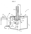
- the cleaning chamber 1 has a central, the drain 4 opposite opening 9 in the upper end wall 10 of the sheet metal housing 3, which is closable with a lid 11. In the embodiment, a central opening 9 is present.
- the opening 9 is circular.
- lid 11 and opening 9 can also be square or rectangular.
- the edge of the opening 9 has an outwardly projecting circumferential gutter 12.
- the lid 11 has a central opening 13 which receives the shaft 14 of the lifting arm 15.
- FIG. 2 and FIG. 3 show a guide 18 for the purpose of forming a telescoping seal assembly.
- the lid 11 has on its inside a collar-like cylindrical extension 19, and the lifting arm 15 is equipped at its end associated with the gripping tool 20 with a cylindrical collar 21. Extension 19 and collar 21 are slidably fitted together.
- Collar 21 is fixed to a bottom 22 on the front side of the lifting arm 15 and has a flange which acts as a driver 23.
- the driver 23 comes from a certain lifting height in operative connection with the lid 11 and is raised.
- the lid 11 is placed on the end wall 10 or an intermediate cover 24 from a certain depression depth.
- the lid 11 is according to FIG. 4 held in a guide 16.
- the guide 16 has a bush 17 around the edge region of the opening 13, in which the lid 11 is slidably mounted along the shaft 14.
- FIG. 2 is on the front wall 10 a loose intermediate cover 24 with a central opening 25.
- the diameter of the central opening 25 may correspond to the diameter of the opening 9 in the end wall 10 or be slightly smaller.
- the diameter of the intermediate cover 24 is substantially larger than the diameter of the opening 9 in the end wall 10 and has an outer circumferential collar 26, with which the intermediate cover 24 rests on the end wall 10.
- the intermediate cover 24 is provided with an outwardly directed web 27.
- the difference in the diameter of the intermediate cover 24 and the opening 9 results in a dimension "B" by which the intermediate cover 24 can be displaced in any direction on the end wall 10. With the gutter 12 and the collar 26 of the sliding portion of the intermediate cover 24 is limited to the end wall 10. Gland 12 and collar 26 act as attacks.
- the lifting arm 15 of the lifting device 28 projects into the cleaning chamber 1.
- the gripping tool 20 with which the cleaning material "G" is held.
- the lid 11 has at the outer edge a circumferential sealing ridge 29 and cooperates with the intermediate cover 24 in such a way that the sealing ridge 29 is approximately flush with little play in the web 27 of the intermediate cover 24 is used and when lowering the lifting arm 15 through the opening. 9 automatically establishes an operative connection by the sealing ridge 29 touches with its end face on the intermediate cover 24.
- FIG. 2 a simplified variant of the sealing arrangement is shown.
- the cover 11 rests with its sealing ridge 29 directly on the end wall 10, and the lid 11 is supported with its sealing ridge 29 on the gutter 12 of the end wall 10.
- the lifting arm 15 is offset from the center of the cleaning chamber 1 to the left in the direction of the nozzles 7 with entrainment of the lid 11.
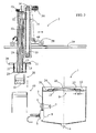
- the lifting arm 15, according to FIG. 1 . 2 . 3 and 4 is advantageously designed as a vertically arranged in guides 30 column and can be moved by a chain drive 31 by the upper end of the lifting arm 15 is connected to a lock 32 with the drive chain 33.
- the drive chain 33 is guided between two pinions 34, 35, wherein a pinion 34 is driven by a motor 36.
- the chain drive 31 is attached to a bracket 37 which is mounted on a trolley 38 or mounted on the trolley 38 carriage 41.
- the trolley 38 moves on guide rails 39 and can transport the lift arm 15 from a position above the tray 40 for the cleaning groove "G" to a position above the opening 9 of the cleaning chamber 1. With the lifting arm 15, a vertical movement is performed.
- the cleaning material "G” can be picked up by the tray 40 and lifted with the lifting arm 15 and lowered into the cleaning chamber 1.
- the working position of the lifting arm 15 within the cleaning chamber 1 can be carried out with the trolley 38 or the carriage 41, a reciprocating movement, so that the cleaning material "G” at any desired location on the spray spray or jet nozzles 7, 8 is guided along during the treatment.
- the lid 11 with the intermediate cover 24 make this Movements with and close the opening 9.
- the lift arm 15 can also be controlled within the cleaning chamber 1 and during the treatment in the vertical direction up and down, so that all points of the laundry "G" can be reached on one side.
- the lifting arm 15 is rotatably mounted with the gripper tool 20 about its longitudinal axis, so that cleaning can be performed by rotation of the gripping tool 20 on all peripheral sides.
- a drive shaft 42 for the gripping tool 20 is continuously supported, which is driven by a motor 43 attached to the other end of the lifting arm 15.
- the carriage 41 is mounted on rails 44 of the trolley 38.
- the guide rails 39 may be routed along a series of cleaning chambers 1 to the tray 40.
- a circular arrangement is conceivable in which a plurality of cleaning chambers 1 are arranged in an arc and the tray 40 is inserted between two adjacent starshuntnl so that dirty laundry "G" removed from the tray 40 and placed in a first cleaning chamber 1, in the first treatment process, for example, a washing process takes place, to a final cleaning chamber 1, in which, for example, a drying process takes place and from there the cleaned laundry "G" is provided in the tray 40 for removal.
- the lifting arm 15 can be moved with the gripping tool 20 independently of the running direction of the trolley 38.
- irregularly arranged cleaning chambers 1 can be approached away from the tray 40 in a 3-coordinate system.
- cleaning chambers 1 arranged in a row and at a distance from a deposit 40 remote from the cleaning chambers 1 can be equipped with laundry "G" as the origin, for example from a conveyor belt, the lifting arm 15 with gripping tool 20 Material “G” receives and raises in a plane above the level of the cleaning chambers 1, the trolley 38, a first cleaning chamber 1 with an X-coordinate drives and the carriage 41 the lifting arm 15 with cleaning material "G” along a Y-coordinate into a Position over the opening 9 and 25 of the cleaning chamber 1 transported. Finally, the lifting arm 15 lowers the gripping tool 20 with the item to be cleaned "G" through the openings 25, 9 and holds it during the treatment, in which position slide 41, trolley 32 and lifting arm 15 perform coordinated movements also washing movements.
- FIG. 1 the position of the transport device 2 in working position of the cleaning chamber 1 and in FIG. 3 the transport device 2 is shown in a position for depositing the laundry "G" on the tray 40. It can be seen that lid 11 and lift arm 15 remain connected.
- FIG. 4 is the side view of the cleaning system shown, in which the carriage 41 is a transport movement of the lifting arm 15 transverse to the direction of movement of the trolley 38.
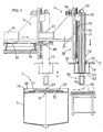
- the cleaning system according to FIG. 5 to 8 and 9 to 11 contains as transport device 2 an industrial robot 45 with a manipulable about multiple axes manipulator arm 46 and a lift arm 47, with a gripping tool 20 at the free end.
- the lid 11 is movably guided in the central opening 48 along the shaft 49 of the lifting arm 47.
- the pendulum bearing 50 is according to FIG. 5 to 8 designed as a ball joint 51 with a ball head 52 and a ball socket 53.
- the ball head 52 is slidably mounted on the shaft 49 of the lifting arm 47 in a guide 54 and the ball socket 53 is located on the lid 11 in the edge region of the opening 48.
- the driver 55 at the end of the lifting arm 47 forms a stop for driving the lid 11 in the Upward movement of the lifting arm 47.
- the gripping tool 20 can be moved up and down with the lifting arm 47 in the guide 54 or moved in the pendulum bearing 50 in a pendulum motion with the manipulator arm 46.
- FIG. 7 shows a rotation of the gripping tool 20 and a pivoting possible, such as FIG. 7 shows.
- the FIG. 7 further shows that the lid 11 is displaced to the right edge of the cleaning chamber 1.
- the FIG. 8th shows the position of the lid 11 shifted to the left edge of the cleaning chamber. 1
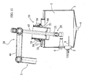
- FIG. 9 to 11 shows a variant of the system FIG. 5 to 8 ,
- the main difference is the special design of the self-aligning bearing 50.
- the others in the FIG. 5 to 8 The parts of the system described below also apply accordingly to the variant FIG. 9 to 11 so that reference is made to the above descriptions.
- the pendulum bearing 50 allows the mobility of the lifting arm 47 with its gripping tool 20 in the treatment chamber 1 in several directions without forming a special hinge between the cover 11 and lift arm 47.
- the function of a pendulum movement of the lifting arm 47 during treatment in the cleaning chamber 1, ie when closed Cover 11, is achieved by a guide body 57 which is inserted with a game 60 in the opening 48 of the lid 11, which is so large that the guide body 57 can be tilted by a certain angle to the horizontal, without causing a frictional Tilting with the lid 11 takes place.
- the game 60 on the other hand should be low enough that a horizontal displacement of the lid 11 on the end wall 10 of the cleaning chamber 1 is made possible with a corresponding horizontal movement of the lifting arm 47.
- the guide body 57 should have an elongated shape, so that a guide in the opening 48 over the entire stroke of the lifting arm 47 takes place.
- the lifting arm 47 passes through the guide body 57 and is secured via a connection 61 sealingly on the shaft 47 of the lifting arm 47.
- Lifting arm 47 and Guide body form with the connection 61 a structural unit.
- a laterally open cage or cylinder can be used with a round or rectangular cross-section.
- a flexible sealing body 58 is attached from liquid-tight material, which is designed as a bellows or cuff and with one end to an unspecified flange of the lid 11 and the other end at the top Edge region of the guide body 57 is attached.
- the sealing body 58 is pressed in accordion-like manner during movements of the lifting arm 47 and pulled apart.
- the lid 11 is held with straps 59 on the guide body 57 or the lifting arm 47.
Landscapes
- Cleaning By Liquid Or Steam (AREA)
- Manipulator (AREA)
Priority Applications (1)
| Application Number | Priority Date | Filing Date | Title |
|---|---|---|---|
| PL11813774T PL2640530T3 (pl) | 2010-11-17 | 2011-11-17 | Przemysłowa instalacja czyszcząca |
Applications Claiming Priority (3)
| Application Number | Priority Date | Filing Date | Title |
|---|---|---|---|
| DE102010051686 | 2010-11-17 | ||
| DE102011112692.2A DE102011112692B4 (de) | 2010-11-17 | 2011-09-07 | Industrielle Reinigungsanlage |
| PCT/DE2011/075277 WO2012065607A1 (de) | 2010-11-17 | 2011-11-17 | Industrielle reinigungsanlage |
Publications (2)
| Publication Number | Publication Date |
|---|---|
| EP2640530A1 EP2640530A1 (de) | 2013-09-25 |
| EP2640530B1 true EP2640530B1 (de) | 2015-04-01 |
Family
ID=45554408
Family Applications (1)
| Application Number | Title | Priority Date | Filing Date |
|---|---|---|---|
| EP11813774.4A Active EP2640530B1 (de) | 2010-11-17 | 2011-11-17 | Industrielle reinigungsanlage |
Country Status (9)
| Country | Link |
|---|---|
| US (1) | US9186708B2 (enExample) |
| EP (1) | EP2640530B1 (enExample) |
| JP (1) | JP2013544183A (enExample) |
| KR (1) | KR20140027912A (enExample) |
| CN (1) | CN103221154B (enExample) |
| DE (1) | DE102011112692B4 (enExample) |
| PL (1) | PL2640530T3 (enExample) |
| RU (1) | RU2568214C2 (enExample) |
| WO (1) | WO2012065607A1 (enExample) |
Families Citing this family (25)
| Publication number | Priority date | Publication date | Assignee | Title |
|---|---|---|---|---|
| DE102014001117A1 (de) | 2014-01-28 | 2015-07-30 | Werner Meissner | Einrichtung für eine Behandlungskammer einer Reinigungsanlage |
| US9968974B2 (en) * | 2014-02-28 | 2018-05-15 | Fives Cinetic Corporation | Assembly and method for removing a robot from an enclosure |
| DE102014003346B4 (de) | 2014-03-07 | 2025-02-06 | Werner Meissner | Reinigungsanlage zur Behandlung von Werkstücken |
| JP6196588B2 (ja) | 2014-07-24 | 2017-09-13 | 株式会社スギノマシン | 送り台装置、および対象物駆動装置 |
| JP6227496B2 (ja) * | 2014-07-24 | 2017-11-08 | 株式会社スギノマシン | 洗浄装置 |
| JP6531972B2 (ja) * | 2014-11-25 | 2019-06-19 | シブヤマシナリー株式会社 | 洗浄装置 |
| DE102015207598A1 (de) * | 2015-04-24 | 2016-10-27 | Fraunhofer-Gesellschaft zur Förderung der angewandten Forschung e.V. | Bildaufnahmevorrichtung zum automatischen Erstellen eines computertomografischen Abbilds von einem Bauteil, Verfahren zum Betrieb einer Bildaufnahmevorrichtung und Inline-Bauteilprüfanlage mit einer Bildaufnahmevorrichtung |
| US9828094B2 (en) * | 2015-07-26 | 2017-11-28 | John B. McMillion | Autonomous cleaning system |
| DE102015011511A1 (de) | 2015-09-03 | 2017-03-09 | Werner Meissner | Einrichtung für eine industrielle Reinigungsanlage |
| DE102015011923A1 (de) | 2015-09-12 | 2017-03-16 | Werner Meissner | Reinigungsarmatur für eine industrielle Reinigungseinrichtung |
| JP6756539B2 (ja) * | 2016-08-04 | 2020-09-16 | オークマ株式会社 | 工作機械 |
| USD865010S1 (en) * | 2017-01-17 | 2019-10-29 | Sugino Machine Limited | Washing machine for machined parts |
| DE102016013245B4 (de) * | 2016-11-08 | 2025-10-16 | Westinghouse Electric Germany Gmbh | Bohrgerät für das Bearbeiten von Rohren in radioaktiver Umgebung |
| DE102018003143A1 (de) | 2018-04-18 | 2019-10-24 | Golo Meißner | Ladestation für eine industrielle Reinigungsanlage |
| US11318506B2 (en) * | 2018-08-16 | 2022-05-03 | Taiwan Semiconductor Manufacturing Company Ltd. | Apparatus for cleaning semiconductor equipment |
| DE102018008841A1 (de) | 2018-11-09 | 2020-05-14 | Werner Meissner | Anlage und Verfahren zur Reinigung und Qualitätsprüfung von Werkstücken |
| DE102018008842A1 (de) | 2018-11-09 | 2020-05-14 | Werner Meissner | Industrielle Reinungsanlage |
| KR102036589B1 (ko) * | 2018-11-14 | 2019-10-25 | 주식회사 윈텍오토메이션 | 직교 로봇을 이용한 초경인서트 고속 검사장비의 초경인서트 클리닝장치 |
| US20210146406A1 (en) * | 2019-11-18 | 2021-05-20 | Ford Global Technologies, Llc | Cleaning apparatus for sensor |
| US20220041139A1 (en) * | 2020-08-05 | 2022-02-10 | Ford Global Technologies, Llc | Sensor cleaning apparatus |
| CN112403989B (zh) * | 2020-10-10 | 2025-05-06 | 苏州爱拓玛机械科技有限公司 | 一种桥壳清洗干燥装置 |
| KR20220059756A (ko) * | 2020-11-03 | 2022-05-10 | 코닝 인코포레이티드 | 유리 시트 세정 장치 |
| CN113894109B (zh) * | 2021-08-17 | 2023-02-21 | 无锡先导智能装备股份有限公司 | 一种除尘机构及激光清洗装置 |
| CN113894072B (zh) * | 2021-09-29 | 2022-10-11 | 东海县红鑫新材料有限公司 | 一种基于循环制备机构的石英砂加工设备及加工方法 |
| DE102023124032A1 (de) * | 2023-09-06 | 2025-03-06 | Maschinenbau Silberhorn GmbH | Greiferarm mit Z-Achsenausgleich |
Family Cites Families (28)
| Publication number | Priority date | Publication date | Assignee | Title |
|---|---|---|---|---|
| US3603037A (en) * | 1969-04-01 | 1971-09-07 | Carborundum Co | Workpiece-treating system |
| JPS5116464U (enExample) * | 1974-07-24 | 1976-02-06 | ||
| US4038155A (en) * | 1976-04-05 | 1977-07-26 | Purex Corporation Ltd. | Energy saving vapor degreasing apparatus |
| JPS5630964U (enExample) * | 1979-08-20 | 1981-03-25 | ||
| JPS6212470Y2 (enExample) * | 1979-10-27 | 1987-03-31 | ||
| DE3242719C2 (de) * | 1981-12-01 | 1986-05-22 | LPW-Reinigungstechnik GmbH, 7024 Filderstadt | Vorrichtung für die Lösungsmittelbehandlung von insbesondere metallischem Behandlungsgut |
| JPS58127396U (ja) * | 1982-02-22 | 1983-08-29 | 株式会社東芝 | 制御棒駆動機構自動分解洗浄装置 |
| JPS5965792U (ja) * | 1982-10-22 | 1984-05-02 | ジヤパン・フイ−ルド株式会社 | 洗浄装置 |
| SU1282926A1 (ru) * | 1985-05-16 | 1987-01-15 | Головное Специализированное Конструкторско-Технологическое Бюро Моечного Оборудования | Установка дл очистки изделий |
| SU1558519A1 (ru) * | 1987-02-13 | 1990-04-23 | Головное Специализированное Конструкторско-Технологическое Бюро Моечного Оборудования | Установка дл очистки изделий |
| US5261715A (en) * | 1988-11-14 | 1993-11-16 | John A. Blatt | Work holder support apparatus |
| US5062758A (en) * | 1989-03-31 | 1991-11-05 | Wentgate Dynaweld, Inc. | Shuttle system for rapidly manipulating a workpiece into and out of an atmospherically controlled chamber for doing work thereon in the chamber |
| US5105932A (en) * | 1990-03-09 | 1992-04-21 | Bryson Iii Charles E | Linear and rotary positioning device |
| US5148714A (en) * | 1990-10-24 | 1992-09-22 | Ag Processing Technology, Inc. | Rotary/linear actuator for closed chamber, and reaction chamber utilizing same |
| DE4125891C2 (de) | 1991-08-05 | 1995-01-19 | Hermann Ziegler | Verfahren zur Reinigung verschmutzter Teile |
| JP2866954B2 (ja) * | 1992-10-19 | 1999-03-08 | 旭エンジニアリング株式会社 | 槽の自動洗浄装置 |
| JPH08340077A (ja) * | 1995-06-12 | 1996-12-24 | Hitachi Cable Ltd | 溶剤液切り方法 |
| JPH0919663A (ja) * | 1995-07-06 | 1997-01-21 | Kyodo Kumiai Ekoro Clean Plaza | 洗浄装置 |
| DE19703310C1 (de) | 1997-01-30 | 1998-04-23 | Meisner Werner | Industrielle Reinigungsanlage |
| JP2001170576A (ja) * | 1999-12-20 | 2001-06-26 | Mitsuo Wazawa | パレット洗浄装置 |
| JP2001232320A (ja) | 2000-02-21 | 2001-08-28 | Sugino Mach Ltd | 缶体洗浄装置 |
| DE10230396B4 (de) | 2002-07-05 | 2010-11-25 | Rösler Oberflächentechnik GmbH | Arbeitskammer |
| DE10314181A1 (de) * | 2003-03-28 | 2004-10-14 | Rösler Oberflächentechnik GmbH | Arbeitskammer |
| DE102005003093B4 (de) * | 2005-01-22 | 2018-12-13 | Ecoclean Gmbh | Reinigungsanlage |
| DE102005031515B4 (de) | 2005-07-06 | 2023-06-01 | Werner Meissner | Industrielle Reinigungsanlage |
| DE102006026171B4 (de) | 2006-06-06 | 2024-03-28 | Werner Meissner | Einrichtung zur Oberflächenbehandlung industrieller Teile |
| DE102007047934A1 (de) | 2007-12-20 | 2009-06-25 | Moll Maschinenbau Gmbh | Vorrichtung und Verfahren zur Reinigung von Werkstücken |
| JP5089628B2 (ja) * | 2009-02-18 | 2012-12-05 | 三菱電機株式会社 | 洗浄装置、洗浄方法および被洗浄体 |
-
2011
- 2011-09-07 DE DE102011112692.2A patent/DE102011112692B4/de active Active
- 2011-11-17 EP EP11813774.4A patent/EP2640530B1/de active Active
- 2011-11-17 RU RU2013122924/05A patent/RU2568214C2/ru active
- 2011-11-17 CN CN201180055379.0A patent/CN103221154B/zh active Active
- 2011-11-17 US US13/988,129 patent/US9186708B2/en active Active
- 2011-11-17 KR KR1020137014757A patent/KR20140027912A/ko not_active Withdrawn
- 2011-11-17 PL PL11813774T patent/PL2640530T3/pl unknown
- 2011-11-17 WO PCT/DE2011/075277 patent/WO2012065607A1/de not_active Ceased
- 2011-11-17 JP JP2013539139A patent/JP2013544183A/ja active Pending
Also Published As
| Publication number | Publication date |
|---|---|
| DE102011112692B4 (de) | 2024-03-28 |
| RU2013122924A (ru) | 2015-01-20 |
| PL2640530T3 (pl) | 2015-08-31 |
| RU2568214C2 (ru) | 2015-11-10 |
| US9186708B2 (en) | 2015-11-17 |
| DE102011112692A1 (de) | 2012-05-24 |
| KR20140027912A (ko) | 2014-03-07 |
| US20130233359A1 (en) | 2013-09-12 |
| JP2013544183A (ja) | 2013-12-12 |
| CN103221154A (zh) | 2013-07-24 |
| CN103221154B (zh) | 2016-07-20 |
| WO2012065607A1 (de) | 2012-05-24 |
| EP2640530A1 (de) | 2013-09-25 |
Similar Documents
| Publication | Publication Date | Title |
|---|---|---|
| EP2640530B1 (de) | Industrielle reinigungsanlage | |
| EP0956163B1 (de) | Industrielle reinigungsanlage | |
| DE19936698C1 (de) | Vorrichtung zur Reinigung von Vulkanisationsformen | |
| EP2913284B1 (de) | Verfahren und Anlage zum Behandeln von Teilen | |
| DE2018862A1 (de) | Warmebehandlungseinnchtung | |
| DE102004002585A1 (de) | Vorrichtung zur Nassbehandlung von Wäsche | |
| EP3165286A1 (de) | Verfahren und vorrichtung zur entölung und/oder reinigung von massenteilen | |
| DE102005031515B4 (de) | Industrielle Reinigungsanlage | |
| DE102010012328A1 (de) | Reinigungsanlage für industrielle Bauteile | |
| DE102015011511A1 (de) | Einrichtung für eine industrielle Reinigungsanlage | |
| DE19938478A1 (de) | Vorrichtung zum Bearbeiten einer beliebigen Fläche | |
| DE102006020679B4 (de) | Schutzvorrichtungen | |
| DE69201494T2 (de) | Roboter, z.B. zum reinigen. | |
| DE102014001934B4 (de) | Reinigungsanlage mit einer Behandlungskammer | |
| DE102013016597A1 (de) | System zum Be- und Entladen von Reinraumanlagen mit großflächigen Substraten | |
| DE102014003346B4 (de) | Reinigungsanlage zur Behandlung von Werkstücken | |
| DE3242719C2 (de) | Vorrichtung für die Lösungsmittelbehandlung von insbesondere metallischem Behandlungsgut | |
| DE102014001117A1 (de) | Einrichtung für eine Behandlungskammer einer Reinigungsanlage | |
| WO2016173859A2 (de) | Saugeinheit sowie sauganlagae mit einer solchen saugeinheit | |
| DE19856191C2 (de) | Anlage zur Wärmebehandlung von Teilen | |
| DE3640144C2 (enExample) | ||
| DE19602374A1 (de) | Transporteinrichtung | |
| DE19647248A1 (de) | Werkstückträger zum Wärmebehandeln von Werkstücken, Vorrichtung zum Entnehmen von Werkstücken aus einem Rollenherdofen und Wärmebehandlungsanlage | |
| DE102015111354A1 (de) | Saugeinheit sowie Sauganlage mit einer solchen Saugeinheit | |
| EP0640439A1 (de) | Vorrichtung für eine Oberflächenbehandlung grosser freiliegender im wesentlichen horizontaler Bodenflächen von Objekten, insbesondere von Schiffen |
Legal Events
| Date | Code | Title | Description |
|---|---|---|---|
| PUAI | Public reference made under article 153(3) epc to a published international application that has entered the european phase |
Free format text: ORIGINAL CODE: 0009012 |
|
| 17P | Request for examination filed |
Effective date: 20130617 |
|
| AK | Designated contracting states |
Kind code of ref document: A1 Designated state(s): AL AT BE BG CH CY CZ DE DK EE ES FI FR GB GR HR HU IE IS IT LI LT LU LV MC MK MT NL NO PL PT RO RS SE SI SK SM TR |
|
| DAX | Request for extension of the european patent (deleted) | ||
| GRAP | Despatch of communication of intention to grant a patent |
Free format text: ORIGINAL CODE: EPIDOSNIGR1 |
|
| INTG | Intention to grant announced |
Effective date: 20140917 |
|
| GRAS | Grant fee paid |
Free format text: ORIGINAL CODE: EPIDOSNIGR3 |
|
| GRAP | Despatch of communication of intention to grant a patent |
Free format text: ORIGINAL CODE: EPIDOSNIGR1 |
|
| GRAA | (expected) grant |
Free format text: ORIGINAL CODE: 0009210 |
|
| INTG | Intention to grant announced |
Effective date: 20150216 |
|
| AK | Designated contracting states |
Kind code of ref document: B1 Designated state(s): AL AT BE BG CH CY CZ DE DK EE ES FI FR GB GR HR HU IE IS IT LI LT LU LV MC MK MT NL NO PL PT RO RS SE SI SK SM TR |
|
| REG | Reference to a national code |
Ref country code: GB Ref legal event code: FG4D Free format text: NOT ENGLISH |
|
| REG | Reference to a national code |
Ref country code: CH Ref legal event code: EP |
|
| REG | Reference to a national code |
Ref country code: IE Ref legal event code: FG4D Free format text: LANGUAGE OF EP DOCUMENT: GERMAN |
|
| REG | Reference to a national code |
Ref country code: DE Ref legal event code: R096 Ref document number: 502011006477 Country of ref document: DE Effective date: 20150513 |
|
| REG | Reference to a national code |
Ref country code: AT Ref legal event code: REF Ref document number: 718762 Country of ref document: AT Kind code of ref document: T Effective date: 20150515 |
|
| REG | Reference to a national code |
Ref country code: NL Ref legal event code: VDEP Effective date: 20150401 |
|
| REG | Reference to a national code |
Ref country code: PL Ref legal event code: T3 |
|
| REG | Reference to a national code |
Ref country code: LT Ref legal event code: MG4D |
|
| PG25 | Lapsed in a contracting state [announced via postgrant information from national office to epo] |
Ref country code: NL Free format text: LAPSE BECAUSE OF FAILURE TO SUBMIT A TRANSLATION OF THE DESCRIPTION OR TO PAY THE FEE WITHIN THE PRESCRIBED TIME-LIMIT Effective date: 20150401 |
|
| PG25 | Lapsed in a contracting state [announced via postgrant information from national office to epo] |
Ref country code: PT Free format text: LAPSE BECAUSE OF FAILURE TO SUBMIT A TRANSLATION OF THE DESCRIPTION OR TO PAY THE FEE WITHIN THE PRESCRIBED TIME-LIMIT Effective date: 20150803 Ref country code: CZ Free format text: LAPSE BECAUSE OF FAILURE TO SUBMIT A TRANSLATION OF THE DESCRIPTION OR TO PAY THE FEE WITHIN THE PRESCRIBED TIME-LIMIT Effective date: 20150401 Ref country code: LT Free format text: LAPSE BECAUSE OF FAILURE TO SUBMIT A TRANSLATION OF THE DESCRIPTION OR TO PAY THE FEE WITHIN THE PRESCRIBED TIME-LIMIT Effective date: 20150401 Ref country code: ES Free format text: LAPSE BECAUSE OF FAILURE TO SUBMIT A TRANSLATION OF THE DESCRIPTION OR TO PAY THE FEE WITHIN THE PRESCRIBED TIME-LIMIT Effective date: 20150401 Ref country code: FI Free format text: LAPSE BECAUSE OF FAILURE TO SUBMIT A TRANSLATION OF THE DESCRIPTION OR TO PAY THE FEE WITHIN THE PRESCRIBED TIME-LIMIT Effective date: 20150401 Ref country code: NO Free format text: LAPSE BECAUSE OF FAILURE TO SUBMIT A TRANSLATION OF THE DESCRIPTION OR TO PAY THE FEE WITHIN THE PRESCRIBED TIME-LIMIT Effective date: 20150701 Ref country code: HR Free format text: LAPSE BECAUSE OF FAILURE TO SUBMIT A TRANSLATION OF THE DESCRIPTION OR TO PAY THE FEE WITHIN THE PRESCRIBED TIME-LIMIT Effective date: 20150401 |
|
| REG | Reference to a national code |
Ref country code: FR Ref legal event code: PLFP Year of fee payment: 5 |
|
| PG25 | Lapsed in a contracting state [announced via postgrant information from national office to epo] |
Ref country code: LV Free format text: LAPSE BECAUSE OF FAILURE TO SUBMIT A TRANSLATION OF THE DESCRIPTION OR TO PAY THE FEE WITHIN THE PRESCRIBED TIME-LIMIT Effective date: 20150401 Ref country code: RS Free format text: LAPSE BECAUSE OF FAILURE TO SUBMIT A TRANSLATION OF THE DESCRIPTION OR TO PAY THE FEE WITHIN THE PRESCRIBED TIME-LIMIT Effective date: 20150401 Ref country code: IS Free format text: LAPSE BECAUSE OF FAILURE TO SUBMIT A TRANSLATION OF THE DESCRIPTION OR TO PAY THE FEE WITHIN THE PRESCRIBED TIME-LIMIT Effective date: 20150801 Ref country code: GR Free format text: LAPSE BECAUSE OF FAILURE TO SUBMIT A TRANSLATION OF THE DESCRIPTION OR TO PAY THE FEE WITHIN THE PRESCRIBED TIME-LIMIT Effective date: 20150702 |
|
| REG | Reference to a national code |
Ref country code: DE Ref legal event code: R097 Ref document number: 502011006477 Country of ref document: DE |
|
| PG25 | Lapsed in a contracting state [announced via postgrant information from national office to epo] |
Ref country code: EE Free format text: LAPSE BECAUSE OF FAILURE TO SUBMIT A TRANSLATION OF THE DESCRIPTION OR TO PAY THE FEE WITHIN THE PRESCRIBED TIME-LIMIT Effective date: 20150401 Ref country code: DK Free format text: LAPSE BECAUSE OF FAILURE TO SUBMIT A TRANSLATION OF THE DESCRIPTION OR TO PAY THE FEE WITHIN THE PRESCRIBED TIME-LIMIT Effective date: 20150401 |
|
| PLBE | No opposition filed within time limit |
Free format text: ORIGINAL CODE: 0009261 |
|
| STAA | Information on the status of an ep patent application or granted ep patent |
Free format text: STATUS: NO OPPOSITION FILED WITHIN TIME LIMIT |
|
| PG25 | Lapsed in a contracting state [announced via postgrant information from national office to epo] |
Ref country code: RO Free format text: LAPSE BECAUSE OF NON-PAYMENT OF DUE FEES Effective date: 20150401 Ref country code: SK Free format text: LAPSE BECAUSE OF FAILURE TO SUBMIT A TRANSLATION OF THE DESCRIPTION OR TO PAY THE FEE WITHIN THE PRESCRIBED TIME-LIMIT Effective date: 20150401 |
|
| 26N | No opposition filed |
Effective date: 20160105 |
|
| PG25 | Lapsed in a contracting state [announced via postgrant information from national office to epo] |
Ref country code: IT Free format text: LAPSE BECAUSE OF FAILURE TO SUBMIT A TRANSLATION OF THE DESCRIPTION OR TO PAY THE FEE WITHIN THE PRESCRIBED TIME-LIMIT Effective date: 20150401 |
|
| PG25 | Lapsed in a contracting state [announced via postgrant information from national office to epo] |
Ref country code: SI Free format text: LAPSE BECAUSE OF FAILURE TO SUBMIT A TRANSLATION OF THE DESCRIPTION OR TO PAY THE FEE WITHIN THE PRESCRIBED TIME-LIMIT Effective date: 20150401 |
|
| PG25 | Lapsed in a contracting state [announced via postgrant information from national office to epo] |
Ref country code: LU Free format text: LAPSE BECAUSE OF FAILURE TO SUBMIT A TRANSLATION OF THE DESCRIPTION OR TO PAY THE FEE WITHIN THE PRESCRIBED TIME-LIMIT Effective date: 20151117 Ref country code: MC Free format text: LAPSE BECAUSE OF FAILURE TO SUBMIT A TRANSLATION OF THE DESCRIPTION OR TO PAY THE FEE WITHIN THE PRESCRIBED TIME-LIMIT Effective date: 20150401 |
|
| REG | Reference to a national code |
Ref country code: CH Ref legal event code: PL |
|
| GBPC | Gb: european patent ceased through non-payment of renewal fee |
Effective date: 20151117 |
|
| PG25 | Lapsed in a contracting state [announced via postgrant information from national office to epo] |
Ref country code: LI Free format text: LAPSE BECAUSE OF NON-PAYMENT OF DUE FEES Effective date: 20151130 Ref country code: CH Free format text: LAPSE BECAUSE OF NON-PAYMENT OF DUE FEES Effective date: 20151130 |
|
| REG | Reference to a national code |
Ref country code: IE Ref legal event code: MM4A |
|
| PG25 | Lapsed in a contracting state [announced via postgrant information from national office to epo] |
Ref country code: GB Free format text: LAPSE BECAUSE OF NON-PAYMENT OF DUE FEES Effective date: 20151117 Ref country code: IE Free format text: LAPSE BECAUSE OF NON-PAYMENT OF DUE FEES Effective date: 20151117 |
|
| REG | Reference to a national code |
Ref country code: FR Ref legal event code: PLFP Year of fee payment: 6 |
|
| PG25 | Lapsed in a contracting state [announced via postgrant information from national office to epo] |
Ref country code: BG Free format text: LAPSE BECAUSE OF FAILURE TO SUBMIT A TRANSLATION OF THE DESCRIPTION OR TO PAY THE FEE WITHIN THE PRESCRIBED TIME-LIMIT Effective date: 20150401 Ref country code: SM Free format text: LAPSE BECAUSE OF FAILURE TO SUBMIT A TRANSLATION OF THE DESCRIPTION OR TO PAY THE FEE WITHIN THE PRESCRIBED TIME-LIMIT Effective date: 20150401 Ref country code: HU Free format text: LAPSE BECAUSE OF FAILURE TO SUBMIT A TRANSLATION OF THE DESCRIPTION OR TO PAY THE FEE WITHIN THE PRESCRIBED TIME-LIMIT; INVALID AB INITIO Effective date: 20111117 |
|
| PG25 | Lapsed in a contracting state [announced via postgrant information from national office to epo] |
Ref country code: SE Free format text: LAPSE BECAUSE OF FAILURE TO SUBMIT A TRANSLATION OF THE DESCRIPTION OR TO PAY THE FEE WITHIN THE PRESCRIBED TIME-LIMIT Effective date: 20150401 Ref country code: CY Free format text: LAPSE BECAUSE OF FAILURE TO SUBMIT A TRANSLATION OF THE DESCRIPTION OR TO PAY THE FEE WITHIN THE PRESCRIBED TIME-LIMIT Effective date: 20150401 |
|
| PG25 | Lapsed in a contracting state [announced via postgrant information from national office to epo] |
Ref country code: BE Free format text: LAPSE BECAUSE OF NON-PAYMENT OF DUE FEES Effective date: 20151130 |
|
| PG25 | Lapsed in a contracting state [announced via postgrant information from national office to epo] |
Ref country code: MT Free format text: LAPSE BECAUSE OF FAILURE TO SUBMIT A TRANSLATION OF THE DESCRIPTION OR TO PAY THE FEE WITHIN THE PRESCRIBED TIME-LIMIT Effective date: 20150401 |
|
| REG | Reference to a national code |
Ref country code: FR Ref legal event code: PLFP Year of fee payment: 7 |
|
| PG25 | Lapsed in a contracting state [announced via postgrant information from national office to epo] |
Ref country code: TR Free format text: LAPSE BECAUSE OF FAILURE TO SUBMIT A TRANSLATION OF THE DESCRIPTION OR TO PAY THE FEE WITHIN THE PRESCRIBED TIME-LIMIT Effective date: 20150401 Ref country code: MK Free format text: LAPSE BECAUSE OF FAILURE TO SUBMIT A TRANSLATION OF THE DESCRIPTION OR TO PAY THE FEE WITHIN THE PRESCRIBED TIME-LIMIT Effective date: 20150401 |
|
| PG25 | Lapsed in a contracting state [announced via postgrant information from national office to epo] |
Ref country code: AL Free format text: LAPSE BECAUSE OF FAILURE TO SUBMIT A TRANSLATION OF THE DESCRIPTION OR TO PAY THE FEE WITHIN THE PRESCRIBED TIME-LIMIT Effective date: 20150401 |
|
| PGFP | Annual fee paid to national office [announced via postgrant information from national office to epo] |
Ref country code: DE Payment date: 20241125 Year of fee payment: 14 |
|
| PGFP | Annual fee paid to national office [announced via postgrant information from national office to epo] |
Ref country code: PL Payment date: 20241106 Year of fee payment: 14 |
|
| PGFP | Annual fee paid to national office [announced via postgrant information from national office to epo] |
Ref country code: FR Payment date: 20241122 Year of fee payment: 14 |
|
| PGFP | Annual fee paid to national office [announced via postgrant information from national office to epo] |
Ref country code: AT Payment date: 20241118 Year of fee payment: 14 |
|
| REG | Reference to a national code |
Ref country code: DE Ref legal event code: R082 Ref document number: 502011006477 Country of ref document: DE Representative=s name: MAUCHER JENKINS PATENTANWAELTE & RECHTSANWAELT, DE |