EP2639811A1 - Electromagnetic relay - Google Patents
Electromagnetic relay Download PDFInfo
- Publication number
- EP2639811A1 EP2639811A1 EP13150041.5A EP13150041A EP2639811A1 EP 2639811 A1 EP2639811 A1 EP 2639811A1 EP 13150041 A EP13150041 A EP 13150041A EP 2639811 A1 EP2639811 A1 EP 2639811A1
- Authority
- EP
- European Patent Office
- Prior art keywords
- contact
- movable
- press
- piece
- yoke
- Prior art date
- Legal status (The legal status is an assumption and is not a legal conclusion. Google has not performed a legal analysis and makes no representation as to the accuracy of the status listed.)
- Withdrawn
Links
Images


Classifications
-
- H—ELECTRICITY
- H01—ELECTRIC ELEMENTS
- H01H—ELECTRIC SWITCHES; RELAYS; SELECTORS; EMERGENCY PROTECTIVE DEVICES
- H01H45/00—Details of relays
- H01H45/12—Ventilating; Cooling; Heating
-
- H—ELECTRICITY
- H01—ELECTRIC ELEMENTS
- H01H—ELECTRIC SWITCHES; RELAYS; SELECTORS; EMERGENCY PROTECTIVE DEVICES
- H01H50/00—Details of electromagnetic relays
- H01H50/54—Contact arrangements
- H01H50/56—Contact spring sets
- H01H50/58—Driving arrangements structurally associated therewith; Mounting of driving arrangements on armature
-
- H—ELECTRICITY
- H01—ELECTRIC ELEMENTS
- H01H—ELECTRIC SWITCHES; RELAYS; SELECTORS; EMERGENCY PROTECTIVE DEVICES
- H01H50/00—Details of electromagnetic relays
- H01H50/54—Contact arrangements
- H01H50/60—Contact arrangements moving contact being rigidly combined with movable part of magnetic circuit
-
- H—ELECTRICITY
- H01—ELECTRIC ELEMENTS
- H01H—ELECTRIC SWITCHES; RELAYS; SELECTORS; EMERGENCY PROTECTIVE DEVICES
- H01H51/00—Electromagnetic relays
- H01H51/02—Non-polarised relays
- H01H51/20—Non-polarised relays with two or more independent armatures
Definitions
- the present invention relates to an electromagnetic relay.
- an electromagnetic relay having a configuration in which a fixed terminal is latched and attached to each spool of each electromagnet block in a press-fitted manner and each flange is connected in parallel to each other so that the electromagnet blocks may be integrally combined (see, for example, Japanese Unexamined Patent Publication No. 2000-315448 ).
- the present invention has been devised to solve the problems described above, and an object thereof is to provide an electromagnetic relay which can sufficiently dissipate the heat generated from a coil to secure desired attracting force even when the electromagnetic relay is miniaturized.
- an electromagnetic relay including: a plurality of electromagnet blocks, each block including an electromagnet configured by winding a coil around an iron core via a spool, a yoke having a to-be-connected portion which is to be connected to a connection portion of one end of the iron core and a rising portion extending laterally from a magnetic pole portion of the iron core, a movable iron piece tumably supported by a distal end of the rising portion of the yoke and attracted to the magnetic pole portion of the iron core by magnetization of the electromagnet; and a contact switching mechanism including a movable contact piece attached to the movable iron piece and provided with a movable contact, and a fixed terminal attached to the spool to integrally combine the plurality of electromagnet blocks and provided with a fixed contact arranged to be brought into contact with and move away from the movable contact, wherein the movable contact piece includes a contact attach
- the surface area of the movable contact piece may be increased in the portion where the movable iron piece is in surface contact with the movable iron piece. Therefore, the heat generated due to the energizing of the coil may be sufficiently dissipated via a portion ranging from the movable iron piece to the first fixed portion of the movable contact piece.
- an electromagnetic relay including: a plurality of electromagnet blocks, each block including an electromagnet configured by winding a coil around an iron core via a spool, a yoke having a to-be-connected portion which is to be connected to a connection portion of one end of the iron core and a rising portion extending laterally from a magnetic pole portion of the iron core, a movable iron piece tumably supported by a distal end of the rising portion of the yoke and attracted to the magnetic pole portion of the iron core by magnetization of the electromagnet; and a contact switching mechanism including a movable contact piece attached to the movable iron piece and provided with a movable contact, and a fixed terminal attached to the spool to integrally combine the plurality of electromagnet blocks and provided with a fixed contact arranged to be brought into contact with and move away from the movable contact, wherein the movable contact piece includes a contact attach
- the surface area of the movable contact piece may be increased in the portion where the movable iron piece is in surface contact with the yoke. Therefore, the heat generated due to the energizing of the coil may be sufficiently dissipated via a portion ranging from the yoke to the second fixed portion of the movable contact piece.
- the respective spools are provided side by side at a position near the other end of the iron core where the magnetic pole portion is arranged , each of the flanges has a press-fitting recess at one side thereof in a direction of parallel arrangement, the fixed terminal has a plurality of press-fitted portions to be press-fitted into the press-fitting recesses of the respective spools, and the press-fitted portions are formed by cutting and raising portions of the fixed terminals in the direction of parallel arrangement.
- the range, where the movable contact piece is arranged, in the flange may be provided so as to avoid only the press-fitting recess formed at one side in the direction of the parallel arrangement. Therefore, the range occupied by the movable contact piece may be increased.
- the press-fitted portion formed in the fixed terminal is formed by cutting and raising, material punching can be performed without waste of material so that an increase in cost can be suppressed.
- the movable contact piece is made of an elastic material with a high thermal conductivity compared with the movable iron piece and the yoke.
- the heat generated due to the energizing of the coil may be more efficiently dissipated via the movable contact piece.
- the surface area of the movable contact piece where the movable contact piece is in surface contact with a component which constitutes the electromagnet block may be increased, the heat generated due to the energizing of the coil may be effectively dissipated. As a result, it becomes possible to prevent the deterioration of the operating characteristic attributable to the increase in temperature.
- FIG. 1 illustrates an electromagnetic relay according to an embodiment of the present invention.
- This electromagnetic relay is configured such that one pair of electromagnet blocks 1 are provided side by side, a contact switching mechanism 2 is provided, and the electromagnet blocks 1 and the contact switching mechanism 2 are encased in a case 3.
- each of the electromagnet blocks 1 is configured such that a coil 6 is wound around an iron core 4 via a spool 5, a yoke 7 is fixed to the iron core 4, and a movable iron piece 8 is turnably attached to the yoke 7.
- the iron core 4 is formed in a bar shape made of a magnetic material and includes a trunk portion 9 having a rectangular cross-section, a flange-shaped magnetic pole portion 10 formed at an upper end portion of the trunk portion 9, and a connection portion 11 that is formed at a lower end of the trunk portion 9 and has a small cross-sectional area compared with the trunk portion 9.
- the magnetic pole portion 10 attracts the movable iron piece 8.
- the connection portion 11 is fitted into a connection hole 32 formed in the yoke 7 described below so as to be integrally combined.
- the spool 5 is a component obtained by performing a molding process with a synthetic resin material and is configured such that flanges 13 and 20 which are substantially rectangular in a plan view are respectively provided at upper and lower end portions of a cylindrical portion 12.
- a central hole of the cylindrical portion 12 is formed to have an internal surface formed along the trunk portion 9 of the iron core 4.
- a recess 14 in which the magnetic pole portion 10 of the iron core 4 is to be arranged is formed in the upper surface of the upper end-side flange 13 of the spool 5 so as to surround an opening of the central hole.
- the lower surface of the magnetic pole portion 10 is in contact with these protrusions 15 so that the position of the magnetic pole portion 10 in the vertical direction may be determined.
- Both ends of a first side of the upper end-side flange 13 project outward, and the yoke 7 is arranged between the projected end portions.
- a step portion 16 is provided in the middle portion of a second side of the upper end-side flange 13 (the opposite side in the longitudinal direction), and a notch 17 is formed therein.
- a portion (contact stand) of a second fixed terminal 35 described below is located in the step portion 16, and a second fixed contact 53 described below is located in the notch 17.
- One flank portion of the second side of the upper end-side flange 13 is relatively thick, and a groove-shaped engagement socket 18 is formed in the middle portion in the vertical direction.
- a distal end portion of the first fixed terminal 34 is press-fitted into the engagement socket 18.
- the other flank portion of the second side of the upper end-side flange 13 projects upward, and a press-fitting recess 19 is formed in the upper surface thereof.
- the press-fitting recess 19 is substantially rectangular in a plan view, and a first press-fitted portion 47 of the first fixed terminal 34 is press-fitted into the press-fitting recess 19.
- Terminal attaching portions 21 each formed of a rectangular hole passing through the upper and lower surfaces and a notch, are formed at both sides of the projected portion, respectively.
- Terminal attaching portions 21 are formed between these terminal attaching portions 21 .
- An insulating wall portion 22 proj ecting upward and an engagement groove 23 which starts from one end of a lower end-side groove and extends toward the insulating wall portion 22.
- An engagement recess 24 is formed in the end face of the insulating wall portion 22 which is near the engagement groove. As illustrated in FIG.
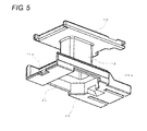
- a relief recess 25 in which a to-be-connected portion 30 of the yoke 7 is arranged is formed in the lower surface of the lower end-side flange 20.
- the relief recess 25 communicates with one end face of the lower end-side flange 20 and a partial upper surface connected thereto via a communicating portion 25a, and the to-be-connected portion 30 of the yoke 7 can be inserted into the relief recess 25 from the side thereof.
- Recesses 26a and 26b in which terminal portions 49 and 57 of the respective fixed terminals 34 and 35 described below are to be arranged are formed in one side surface of the lower end-side flange 20. However, the recesses 26a and 26b are provided such that the side surfaces thereof are located between the pair of electromagnet blocks 1 so as to be opposite to each other.
- the coil 6 is wound around the trunk portion 9 of the spool 5, and extension lines of the coil 6 are wound around and attached to a pair of coil terminals 27, which are respectively press-fitted and fixed to the lower end-side flange 20 of the spool 5.
- Each of the coil terminals 27 includes a winding portion 28 around which the extension line of the coil 6 is wound, and a terminal portion 29.
- a base portion of the winding portion 28 is press-fitted into and fixed by a rectangular hole of the terminal attaching portion 21 and an upper portion of the terminal portion 29 is press-fitted into and fixed by the notch.
- the yoke 7 is obtained by bending a plate member of a magnetic material into an approximately L shape formed of the to-be-connected portion 30 and a rising portion 31.
- the to-be-connected portion 30 is provided with a connection hole 32 to which the connection portion 11 of the iron core 4 is connected.
- the rising portion 31 is provided with riveting proj ections 31a formed at a predetermined interval in a widthwise direction.
- the movable iron piece 8 is a plate member of a magnetic material which is chamfered at corners of the distal end thereof so that the distal end of the movable iron piece 8 has a narrower width than the other portion.
- Supporting pieces 8a project from both ends of the rear end face of the movable iron piece 8, respectively, and a slot 8b extending from the upper surface to the lower surface is provided between the supporting pieces 8a. Riveting projections 8c are formed at a predetermined interval on the upper surface of the movable iron piece 8.
- the movable iron piece 8 is tumably supported by the upper end of the rising portion 31 of the yoke 7 so as to turn about the position (the upper end corner of the rising portion 31 of the yoke 7) where the lower surface of the movable iron piece 8 and the supporting piece 8a cross each other.
- a magnetic closed loop is formed by the iron core 4, the yoke 7, and the movable iron piece 8 so that the leakage of magnetic flux may be controlled.
- the contact switching mechanism 2 includes a movable contact piece 33 to be attached to the movable iron piece 8, and a first fixed terminal 34 and a second fixed terminal 35 to be attached to the spool 5.
- the movable contact piece 33 has conductivity and elasticity, and is formed of a thin plate made of a material (for example, a copper-based alloy) with a heat transfer coefficient higher than that of the movable iron piece 8 and the yoke 7.
- the movable contact piece 33 includes a contact attaching portion 36, a horizontal fixed portion 37, a vertical fixed portion 38, and a movable terminal portion 39, which are arranged in this order from the distal end side.
- the contact attaching portion 36 is chamfered at one corner of the distal end thereof and has two arc-shaped notches at the side edge which is opposite to the side with the chamfered corner.
- the movable contact 40 is riveted and fixed to the contact attaching portion 36.
- the horizontal fixed portion 37 is connected to the contact attaching portion 36 via a first connection portion 41 which extends upward by the thickness of the movable iron piece 8 from the horizontal fixed portion 37, and extends over the upper surface of the movable iron piece 8.
- the horizontal fixed portion 37 has almost the same width dimension as the movable iron piece 8, and has a maximum surface area that can be designed.
- the horizontal fixed portion 37 is provided with two through-holes 37a at both sides thereof, and the projections 8c are inserted and riveted into the through-holes 37a so that the horizontal fixed portion 37 is fixed to the movable contact piece 8 (see FIG. 8 ).
- the horizontal fixed portion 37 and the vertical fixed portion 38 are connected to each other via a second connection portion 42 of a small width which is bent at about a right angle along the movable iron piece 8 and the yoke 7.
- the spring force exerted on the movable iron piece 8 is determined by the second connection portion 42.
- the vertical fixed portion 38 has a width dimension almost the same as the width dimension of the yoke 7, and has the maximum surface area that can be designed, similarly to the horizontal fixed portion 37.
- the vertical fixed portion 38 is provided with two through-holes 38a at both sides thereof, respectively, and projections 31a are inserted and riveted into the through-holes 38a so that the vertical fixed portion 38 is fixed to the yoke 7.
- the horizontal fixed portion 37 and the vertical fixed portion 38 have the maximum surface areas that can be designed (see FIG. 9 ). For this reason, the heat generated due to the energizing of the coil 6 can be effectively dissipated via the horizontal fixed portion 37 and the vertical fixed portion 38.
- the first fixed terminal 34 is obtained by bending a conductive plate member at about a right angle in almost the middle portion so as to form a first horizontal portion 43 and a first vertical portion 44.
- the first horizontal portion 43 is connected to a first contact stand 45 of the identical shape.
- Each of the contact stands is provided with a through-hole, and a first fixed contact 46 is riveted and fixed to the through-hole from the lower surface side.
- Each of the first contact stands 45 is chamfered at the corner of the distal end of one side edge, and a first press-fitted portion 47 bends and extends downward from a corner of the base portion.
- Each of the first press-fitted portions 47 is formed in a vertical portion which is perpendicular to the fixed contact, and has the width and thickness that gradually decrease toward the distal end.
- the first vertical portion 44 is bent such that it may be laterally displaced from a portion connected to the first horizontal portion 43, and the first vertical portion 44 includes an intermediate portion 48 arranged in the recess 26b of the spool 5, and a terminal portion 49 projecting from the lower surface of the spool 5.
- the second fixed terminal 35 is obtained by bending a conductive plate member at about a right angle in almost the middle portion so as to form a second horizontal portion 50 and a second vertical portion 51.
- Second contact stands 52 project from one side edge of the second horizontal portion 50 at a predetermined interval.
- Each of the second contact stands 52 is provided with a through-hole, and a second fixed contact 53 is riveted and fixed to the through-hole from the upper surface side.
- An upper-side second press-fitted portion 54 projects from one of the second contact stands 52.
- the side edge portion of the other one of the second contact stands also functions as an upper-side second press-fitted portion 54.
- Each of the upper-side second press-fitted portions 54 is press-fitted into the engagement socket 18 formed in the upper end-side flange 13 of the spool 5.
- Slit-shaped openings are formed in a connection portion (curved portion) between the second horizontal portion 50 and the second vertical portion 51, especially at the positions corresponding to the respective second contact stands 52.
- Lower-side second press-fitted portions 55 project downward from the lower edge of the second vertical portion 51, especially at the positions corresponding to the respective upper-side second press-fitted portions 54, and then bend to extend in the horizontal direction.
- the vertical portion of each of the lower-side second press-fitted portions 55 is provided with a rectangular opening which is formed to be near the horizontal portion.
- Each of the lower-side second press-fitted portions 55 is press-fitted into the engagement recess 24 via the engagement groove 23 formed in the lower end-side flange 20 of the spool 5.
- One end of the second vertical portion 51 includes an intermediate portion 56 which is bent at about a right angle and a terminal portion 57 extending downward therefrom.
- the coil 6 is wound around the spool 5, the pair of coil terminals 27 are press-fitted into and attached to the respective terminal attaching portions 21 of the lower end-side flange 20, and the extension lines of the coil 6 are wound and attached thereto, respectively.
- the to-be-connected portion 30 of the yoke 7 is inserted into the relief recess 25 in a lateral direction via the opening formed in the lower end-side flange 20 of the spool 5, and the rising portion 31 of the yoke 7 is positioned at the side of the wound coil 6.
- the iron core 4 is inserted into the central hole of the spool 5 from above, and the connection portion 11 at the distal end of the iron core 4 is fitted into the connection hole 32 of the yoke 7.
- the movable contact piece 33 is riveted and fixed to the movable iron piece 8, and the movable contact piece 33 is also riveted and fixed to the yoke 7 so that the electromagnet block 1 is completed. In this state, the movable iron piece 8 is kept away from the magnetic pole portion 10 of the iron core 4 due to the spring force of the movable contact piece 33.
- two completed electromagnet blocks 1 are installed side by side, and both are integrally combined by the second fixed terminal 35. That is, the second fixed terminal 35 is assembled from the side of the pair of electromagnet blocks 1 arranged side by side.
- the upper-side second press-fitted portion 54 of the second fixed terminal 35 is press-fitted into the engagement socket 18 formed in the upper end-side flange 13 of the spool 5, and the lower-side second press-fitted portion 55 is press-fitted into the engagement recess 24 via the engagement groove 23 formed in the lower end-side flange 20.
- the intermediate portion 56 of the second fixed terminal 35 is positioned in the recess 26a formed in the lower end-side flange 20 of one of the electromagnet blocks 1, and the intermediate portion 56 is not projected from the side of the spool 5.
- the connection of the electromagnet blocks 1 becomes stronger by the first fixed terminal 34. That is, the first fixed terminal 34 is assembled to the electromagnet blocks 1 integrally combined, from above. At this time, the first press-fitted portion 47 is press-fitted into the press-fitting recess 19 formed in the upper end-side flange 13 of the spool 5. In this state, the intermediate portion 48 of the first fixed terminal 34 is positioned in the recess 26b formed in the lower end-side flange 20 of the other one of the electromagnet blocks 1, and the intermediate portion 48 is not projected from the side of the spool 5.
- the operation of the magnetic relay will be described. Under a condition in which the coil 6 is not energized and the electromagnet blocks 1 are not yet magnetized, the movable iron piece 8 is turned about the upper end corner of the yoke 7 due to the spring force of the movable contact piece 33 such that the movable iron piece 8 moves away from the magnetic pole portion 10 of the iron core 4. Next, the movable contact 40 is brought into contact with the first fixed contact 46.
- the movable iron piece 8 is attracted to the magnetic pole portion 10 of the iron core 4 and is turned against the spring force of the movable contact piece 33. Therefore, the movable contact 40 moves away from the first fixed contact 46, and comes into contact with the second fixed contact 53.
- the present invention is not limited to the configuration described in the preferred embodiment and can be modified in various ways.
- electromagnet blocks 1 are provided side by side in the above-described embodiment, three or more electromagnet blocks may be also provided.
- the first fixed terminal 34 and the second fixed terminal 35 may be further extended, and the contact stands and the press-fitted portions are increased in number so as to correspond to the increased number of the electromagnet blocks 1.
Landscapes
- Physics & Mathematics (AREA)
- Electromagnetism (AREA)
- Electromagnets (AREA)
Applications Claiming Priority (1)
| Application Number | Priority Date | Filing Date | Title |
|---|---|---|---|
| JP2012059052A JP2013196763A (ja) | 2012-03-15 | 2012-03-15 | 電磁継電器 |
Publications (1)
| Publication Number | Publication Date |
|---|---|
| EP2639811A1 true EP2639811A1 (en) | 2013-09-18 |
Family
ID=47504764
Family Applications (1)
| Application Number | Title | Priority Date | Filing Date |
|---|---|---|---|
| EP13150041.5A Withdrawn EP2639811A1 (en) | 2012-03-15 | 2013-01-02 | Electromagnetic relay |
Country Status (4)
| Country | Link |
|---|---|
| US (1) | US8884727B2 (ja) |
| EP (1) | EP2639811A1 (ja) |
| JP (1) | JP2013196763A (ja) |
| CN (1) | CN103311053B (ja) |
Cited By (1)
| Publication number | Priority date | Publication date | Assignee | Title |
|---|---|---|---|---|
| EP3367413A1 (en) * | 2014-07-28 | 2018-08-29 | Fujitsu Component Limited | Electromagnetic relay and coil terminal |
Families Citing this family (9)
| Publication number | Priority date | Publication date | Assignee | Title |
|---|---|---|---|---|
| US20140247099A1 (en) * | 2013-03-01 | 2014-09-04 | Lear Corporation | Apparatus and method for preventing a relay from freezing |
| CN103700545B (zh) * | 2013-12-09 | 2016-02-24 | 乐山东风汽车电器有限公司 | 一种触头自适应的电磁开关 |
| CN106024526B (zh) * | 2016-06-20 | 2018-05-22 | 惠州亿纬控股有限公司 | 一种用于高压直流的拍合式电磁继电器 |
| CN106206166B (zh) * | 2016-08-29 | 2018-07-10 | 厦门宏发信号电子有限公司 | 一种注塑轭铁的电磁继电器 |
| JP1592933S (ja) * | 2017-03-15 | 2017-12-11 | ||
| JP7029284B2 (ja) * | 2017-12-12 | 2022-03-03 | パナソニックIpマネジメント株式会社 | 接点装置及び電磁継電器 |
| WO2020008756A1 (ja) * | 2018-07-04 | 2020-01-09 | パナソニックIpマネジメント株式会社 | 電子部品モジュール |
| CN109727816B (zh) * | 2019-01-16 | 2023-12-12 | 三友联众集团股份有限公司 | 一种结构改良式继电器 |
| JP7361593B2 (ja) | 2019-12-19 | 2023-10-16 | 富士通コンポーネント株式会社 | 電磁継電器 |
Citations (3)
| Publication number | Priority date | Publication date | Assignee | Title |
|---|---|---|---|---|
| US4816794A (en) * | 1986-07-30 | 1989-03-28 | Omron Tateisi Electronics Co. | Electromagnetic relay |
| EP1050895A2 (en) * | 1999-05-06 | 2000-11-08 | Omron Corporation | Electromagnetic relay |
| EP1284493A2 (en) * | 2001-08-17 | 2003-02-19 | Nec Tokin Iwate, Ltd. | Electromagnetic relay |
Family Cites Families (5)
| Publication number | Priority date | Publication date | Assignee | Title |
|---|---|---|---|---|
| JP3593774B2 (ja) * | 1996-01-09 | 2004-11-24 | オムロン株式会社 | 電磁継電器 |
| JP3898021B2 (ja) * | 2001-10-05 | 2007-03-28 | 株式会社タイコーデバイス | 電磁継電器 |
| JP4453875B2 (ja) * | 2002-11-15 | 2010-04-21 | タイコ エレクトロニクス アンプ ゲゼルシャフト ミット ベシュレンクテル ハウツンク | 電磁リレー |
| JP2004172036A (ja) * | 2002-11-22 | 2004-06-17 | Omron Corp | 電磁リレー |
| JP4190379B2 (ja) * | 2003-09-12 | 2008-12-03 | 富士通コンポーネント株式会社 | 複合型電磁継電器 |
-
2012
- 2012-03-15 JP JP2012059052A patent/JP2013196763A/ja active Pending
- 2012-12-20 US US13/723,162 patent/US8884727B2/en active Active
-
2013
- 2013-01-02 EP EP13150041.5A patent/EP2639811A1/en not_active Withdrawn
- 2013-01-04 CN CN201310001418.XA patent/CN103311053B/zh active Active
Patent Citations (4)
| Publication number | Priority date | Publication date | Assignee | Title |
|---|---|---|---|---|
| US4816794A (en) * | 1986-07-30 | 1989-03-28 | Omron Tateisi Electronics Co. | Electromagnetic relay |
| EP1050895A2 (en) * | 1999-05-06 | 2000-11-08 | Omron Corporation | Electromagnetic relay |
| JP2000315448A (ja) | 1999-05-06 | 2000-11-14 | Omron Corp | 電磁リレー |
| EP1284493A2 (en) * | 2001-08-17 | 2003-02-19 | Nec Tokin Iwate, Ltd. | Electromagnetic relay |
Cited By (3)
| Publication number | Priority date | Publication date | Assignee | Title |
|---|---|---|---|---|
| EP3367413A1 (en) * | 2014-07-28 | 2018-08-29 | Fujitsu Component Limited | Electromagnetic relay and coil terminal |
| US10242829B2 (en) | 2014-07-28 | 2019-03-26 | Fujitsu Component Limited | Electromagnetic relay and coil terminal |
| US11120961B2 (en) | 2014-07-28 | 2021-09-14 | Fujitsu Component Limited | Electromagnetic relay and coil terminal |
Also Published As
| Publication number | Publication date |
|---|---|
| CN103311053A (zh) | 2013-09-18 |
| JP2013196763A (ja) | 2013-09-30 |
| US8884727B2 (en) | 2014-11-11 |
| CN103311053B (zh) | 2016-11-16 |
| US20130241679A1 (en) | 2013-09-19 |
Similar Documents
| Publication | Publication Date | Title |
|---|---|---|
| US8884727B2 (en) | Electromagnetic relay | |
| US6903638B2 (en) | Complex electromagnetic relay | |
| KR100388768B1 (ko) | 전자기 릴레이 | |
| JP4650575B2 (ja) | 電磁リレー | |
| EP1592036B1 (en) | Electromagnetic relay | |
| US6995639B2 (en) | Electromagnetic relay | |
| US8228143B2 (en) | Assembly of electromagnetic relay and circuit board | |
| EP3021341B1 (en) | Contact mechanism | |
| EP2701173B1 (en) | Electromagnet device and electromagnetic relay using the same | |
| JP6168785B2 (ja) | 有極電磁継電器 | |
| US10665406B2 (en) | Contact mechanism and an electromagnetic relay provided therewith | |
| CN101872696B (zh) | 电磁接触器 | |
| TWI430316B (zh) | 電磁繼電器 | |
| CN105531789A (zh) | 电磁接触器 | |
| US6879229B2 (en) | Electromagnetic relay | |
| US8026782B2 (en) | Magnet system for an electrical actuator | |
| US6731191B2 (en) | DC electromagnet | |
| US10204756B2 (en) | Coil terminal and electromagnetic relay provided therewith | |
| JP6079054B2 (ja) | 電磁石装置およびこれを用いた電磁継電器 | |
| JP6830259B2 (ja) | 電磁継電器 | |
| JP4363462B2 (ja) | 高周波リレー | |
| JP2023128905A (ja) | 電磁継電器 | |
| JPH0112369Y2 (ja) | ||
| JP2018037164A (ja) | 外部端子及び電磁リレー | |
| JPH10214551A (ja) | 電磁リレー |
Legal Events
| Date | Code | Title | Description |
|---|---|---|---|
| PUAI | Public reference made under article 153(3) epc to a published international application that has entered the european phase |
Free format text: ORIGINAL CODE: 0009012 |
|
| AK | Designated contracting states |
Kind code of ref document: A1 Designated state(s): AL AT BE BG CH CY CZ DE DK EE ES FI FR GB GR HR HU IE IS IT LI LT LU LV MC MK MT NL NO PL PT RO RS SE SI SK SM TR |
|
| AX | Request for extension of the european patent |
Extension state: BA ME |
|
| 17P | Request for examination filed |
Effective date: 20140318 |
|
| RBV | Designated contracting states (corrected) |
Designated state(s): AL AT BE BG CH CY CZ DE DK EE ES FI FR GB GR HR HU IE IS IT LI LT LU LV MC MK MT NL NO PL PT RO RS SE SI SK SM TR |
|
| 17Q | First examination report despatched |
Effective date: 20160706 |
|
| R17C | First examination report despatched (corrected) |
Effective date: 20160819 |
|
| STAA | Information on the status of an ep patent application or granted ep patent |
Free format text: STATUS: EXAMINATION IS IN PROGRESS |
|
| STAA | Information on the status of an ep patent application or granted ep patent |
Free format text: STATUS: THE APPLICATION HAS BEEN WITHDRAWN |
|
| 18W | Application withdrawn |
Effective date: 20171206 |