EP2630397B1 - Batterieanordnung mit einem kühlflüssigkeits-verteilerschlauch - Google Patents
Batterieanordnung mit einem kühlflüssigkeits-verteilerschlauch Download PDFInfo
- Publication number
- EP2630397B1 EP2630397B1 EP11770704.2A EP11770704A EP2630397B1 EP 2630397 B1 EP2630397 B1 EP 2630397B1 EP 11770704 A EP11770704 A EP 11770704A EP 2630397 B1 EP2630397 B1 EP 2630397B1
- Authority
- EP
- European Patent Office
- Prior art keywords
- hose
- end piece
- hose end
- battery system
- thickened region
- Prior art date
- Legal status (The legal status is an assumption and is not a legal conclusion. Google has not performed a legal analysis and makes no representation as to the accuracy of the status listed.)
- Active
Links
Images


Classifications
-
- H—ELECTRICITY
- H01—ELECTRIC ELEMENTS
- H01M—PROCESSES OR MEANS, e.g. BATTERIES, FOR THE DIRECT CONVERSION OF CHEMICAL ENERGY INTO ELECTRICAL ENERGY
- H01M10/00—Secondary cells; Manufacture thereof
- H01M10/60—Heating or cooling; Temperature control
- H01M10/63—Control systems
- H01M10/633—Control systems characterised by algorithms, flow charts, software details or the like
-
- F—MECHANICAL ENGINEERING; LIGHTING; HEATING; WEAPONS; BLASTING
- F16—ENGINEERING ELEMENTS AND UNITS; GENERAL MEASURES FOR PRODUCING AND MAINTAINING EFFECTIVE FUNCTIONING OF MACHINES OR INSTALLATIONS; THERMAL INSULATION IN GENERAL
- F16L—PIPES; JOINTS OR FITTINGS FOR PIPES; SUPPORTS FOR PIPES, CABLES OR PROTECTIVE TUBING; MEANS FOR THERMAL INSULATION IN GENERAL
- F16L11/00—Hoses, i.e. flexible pipes
- F16L11/04—Hoses, i.e. flexible pipes made of rubber or flexible plastics
- F16L11/12—Hoses, i.e. flexible pipes made of rubber or flexible plastics with arrangements for particular purposes, e.g. specially profiled, with protecting layer, heated, electrically conducting
- F16L11/122—Hoses provided with integrated fixing means, e.g. hooks
-
- F—MECHANICAL ENGINEERING; LIGHTING; HEATING; WEAPONS; BLASTING
- F16—ENGINEERING ELEMENTS AND UNITS; GENERAL MEASURES FOR PRODUCING AND MAINTAINING EFFECTIVE FUNCTIONING OF MACHINES OR INSTALLATIONS; THERMAL INSULATION IN GENERAL
- F16L—PIPES; JOINTS OR FITTINGS FOR PIPES; SUPPORTS FOR PIPES, CABLES OR PROTECTIVE TUBING; MEANS FOR THERMAL INSULATION IN GENERAL
- F16L11/00—Hoses, i.e. flexible pipes
- F16L11/04—Hoses, i.e. flexible pipes made of rubber or flexible plastics
- F16L11/12—Hoses, i.e. flexible pipes made of rubber or flexible plastics with arrangements for particular purposes, e.g. specially profiled, with protecting layer, heated, electrically conducting
- F16L11/121—Hoses, i.e. flexible pipes made of rubber or flexible plastics with arrangements for particular purposes, e.g. specially profiled, with protecting layer, heated, electrically conducting specially profiled cross sections
-
- F—MECHANICAL ENGINEERING; LIGHTING; HEATING; WEAPONS; BLASTING
- F16—ENGINEERING ELEMENTS AND UNITS; GENERAL MEASURES FOR PRODUCING AND MAINTAINING EFFECTIVE FUNCTIONING OF MACHINES OR INSTALLATIONS; THERMAL INSULATION IN GENERAL
- F16L—PIPES; JOINTS OR FITTINGS FOR PIPES; SUPPORTS FOR PIPES, CABLES OR PROTECTIVE TUBING; MEANS FOR THERMAL INSULATION IN GENERAL
- F16L33/00—Arrangements for connecting hoses to rigid members; Rigid hose-connectors, i.e. single members engaging both hoses
- F16L33/02—Hose-clips
- F16L33/025—Hose-clips tightened by deforming radially extending loops or folds
-
- F—MECHANICAL ENGINEERING; LIGHTING; HEATING; WEAPONS; BLASTING
- F16—ENGINEERING ELEMENTS AND UNITS; GENERAL MEASURES FOR PRODUCING AND MAINTAINING EFFECTIVE FUNCTIONING OF MACHINES OR INSTALLATIONS; THERMAL INSULATION IN GENERAL
- F16L—PIPES; JOINTS OR FITTINGS FOR PIPES; SUPPORTS FOR PIPES, CABLES OR PROTECTIVE TUBING; MEANS FOR THERMAL INSULATION IN GENERAL
- F16L33/00—Arrangements for connecting hoses to rigid members; Rigid hose-connectors, i.e. single members engaging both hoses
- F16L33/28—Arrangements for connecting hoses to rigid members; Rigid hose-connectors, i.e. single members engaging both hoses for hoses with one end terminating in a radial flange or collar
-
- F—MECHANICAL ENGINEERING; LIGHTING; HEATING; WEAPONS; BLASTING
- F16—ENGINEERING ELEMENTS AND UNITS; GENERAL MEASURES FOR PRODUCING AND MAINTAINING EFFECTIVE FUNCTIONING OF MACHINES OR INSTALLATIONS; THERMAL INSULATION IN GENERAL
- F16L—PIPES; JOINTS OR FITTINGS FOR PIPES; SUPPORTS FOR PIPES, CABLES OR PROTECTIVE TUBING; MEANS FOR THERMAL INSULATION IN GENERAL
- F16L41/00—Branching pipes; Joining pipes to walls
- F16L41/02—Branch units, e.g. made in one piece, welded, riveted
- F16L41/03—Branch units, e.g. made in one piece, welded, riveted comprising junction pieces for four or more pipe members
-
- H—ELECTRICITY
- H01—ELECTRIC ELEMENTS
- H01M—PROCESSES OR MEANS, e.g. BATTERIES, FOR THE DIRECT CONVERSION OF CHEMICAL ENERGY INTO ELECTRICAL ENERGY
- H01M10/00—Secondary cells; Manufacture thereof
- H01M10/42—Methods or arrangements for servicing or maintenance of secondary cells or secondary half-cells
- H01M10/48—Accumulators combined with arrangements for measuring, testing or indicating the condition of cells, e.g. the level or density of the electrolyte
- H01M10/486—Accumulators combined with arrangements for measuring, testing or indicating the condition of cells, e.g. the level or density of the electrolyte for measuring temperature
-
- H—ELECTRICITY
- H01—ELECTRIC ELEMENTS
- H01M—PROCESSES OR MEANS, e.g. BATTERIES, FOR THE DIRECT CONVERSION OF CHEMICAL ENERGY INTO ELECTRICAL ENERGY
- H01M10/00—Secondary cells; Manufacture thereof
- H01M10/60—Heating or cooling; Temperature control
- H01M10/61—Types of temperature control
- H01M10/613—Cooling or keeping cold
-
- H—ELECTRICITY
- H01—ELECTRIC ELEMENTS
- H01M—PROCESSES OR MEANS, e.g. BATTERIES, FOR THE DIRECT CONVERSION OF CHEMICAL ENERGY INTO ELECTRICAL ENERGY
- H01M10/00—Secondary cells; Manufacture thereof
- H01M10/60—Heating or cooling; Temperature control
- H01M10/62—Heating or cooling; Temperature control specially adapted for specific applications
- H01M10/625—Vehicles
-
- H—ELECTRICITY
- H01—ELECTRIC ELEMENTS
- H01M—PROCESSES OR MEANS, e.g. BATTERIES, FOR THE DIRECT CONVERSION OF CHEMICAL ENERGY INTO ELECTRICAL ENERGY
- H01M10/00—Secondary cells; Manufacture thereof
- H01M10/60—Heating or cooling; Temperature control
- H01M10/65—Means for temperature control structurally associated with the cells
- H01M10/656—Means for temperature control structurally associated with the cells characterised by the type of heat-exchange fluid
- H01M10/6567—Liquids
- H01M10/6568—Liquids characterised by flow circuits, e.g. loops, located externally to the cells or cell casings
-
- H—ELECTRICITY
- H01—ELECTRIC ELEMENTS
- H01M—PROCESSES OR MEANS, e.g. BATTERIES, FOR THE DIRECT CONVERSION OF CHEMICAL ENERGY INTO ELECTRICAL ENERGY
- H01M50/00—Constructional details or processes of manufacture of the non-active parts of electrochemical cells other than fuel cells, e.g. hybrid cells
- H01M50/20—Mountings; Secondary casings or frames; Racks, modules or packs; Suspension devices; Shock absorbers; Transport or carrying devices; Holders
- H01M50/204—Racks, modules or packs for multiple batteries or multiple cells
- H01M50/207—Racks, modules or packs for multiple batteries or multiple cells characterised by their shape
- H01M50/209—Racks, modules or packs for multiple batteries or multiple cells characterised by their shape adapted for prismatic or rectangular cells
-
- H—ELECTRICITY
- H01—ELECTRIC ELEMENTS
- H01M—PROCESSES OR MEANS, e.g. BATTERIES, FOR THE DIRECT CONVERSION OF CHEMICAL ENERGY INTO ELECTRICAL ENERGY
- H01M50/00—Constructional details or processes of manufacture of the non-active parts of electrochemical cells other than fuel cells, e.g. hybrid cells
- H01M50/20—Mountings; Secondary casings or frames; Racks, modules or packs; Suspension devices; Shock absorbers; Transport or carrying devices; Holders
- H01M50/204—Racks, modules or packs for multiple batteries or multiple cells
- H01M50/207—Racks, modules or packs for multiple batteries or multiple cells characterised by their shape
- H01M50/213—Racks, modules or packs for multiple batteries or multiple cells characterised by their shape adapted for cells having curved cross-section, e.g. round or elliptic
-
- H—ELECTRICITY
- H01—ELECTRIC ELEMENTS
- H01M—PROCESSES OR MEANS, e.g. BATTERIES, FOR THE DIRECT CONVERSION OF CHEMICAL ENERGY INTO ELECTRICAL ENERGY
- H01M50/00—Constructional details or processes of manufacture of the non-active parts of electrochemical cells other than fuel cells, e.g. hybrid cells
- H01M50/20—Mountings; Secondary casings or frames; Racks, modules or packs; Suspension devices; Shock absorbers; Transport or carrying devices; Holders
- H01M50/262—Mountings; Secondary casings or frames; Racks, modules or packs; Suspension devices; Shock absorbers; Transport or carrying devices; Holders with fastening means, e.g. locks
-
- H—ELECTRICITY
- H01—ELECTRIC ELEMENTS
- H01M—PROCESSES OR MEANS, e.g. BATTERIES, FOR THE DIRECT CONVERSION OF CHEMICAL ENERGY INTO ELECTRICAL ENERGY
- H01M2220/00—Batteries for particular applications
- H01M2220/20—Batteries in motive systems, e.g. vehicle, ship, plane
-
- Y—GENERAL TAGGING OF NEW TECHNOLOGICAL DEVELOPMENTS; GENERAL TAGGING OF CROSS-SECTIONAL TECHNOLOGIES SPANNING OVER SEVERAL SECTIONS OF THE IPC; TECHNICAL SUBJECTS COVERED BY FORMER USPC CROSS-REFERENCE ART COLLECTIONS [XRACs] AND DIGESTS
- Y02—TECHNOLOGIES OR APPLICATIONS FOR MITIGATION OR ADAPTATION AGAINST CLIMATE CHANGE
- Y02E—REDUCTION OF GREENHOUSE GAS [GHG] EMISSIONS, RELATED TO ENERGY GENERATION, TRANSMISSION OR DISTRIBUTION
- Y02E60/00—Enabling technologies; Technologies with a potential or indirect contribution to GHG emissions mitigation
- Y02E60/10—Energy storage using batteries
Definitions
- the invention further relates to a battery assembly for electric or hybrid vehicles.
- a hose clamp When installing a hose on a hose nozzle, a hose clamp is often used to fix the hose on the hose nozzle and to ensure a secure and permanent seal.
- the workflow is usually that first the hose clamp is pushed loosely over the hose, a Schlauchend demo is then pushed over the hose nozzle, then the hose clamp is positioned and held in an assembly area in the region of the Schlauchend unanimouses and then finally fixed. When attaching the hose clamp this is pulled together so that the hose is pressed against the hose nozzle by the hose clamp.
- Such a hose clamp attachment is z. B. off DE 88 08 680 U1 known.
- Other hose assemblies are from the DE 103 49 527 A1 , of the EP 1 338 840 A1 , of the DE 195 01 615 A1 , of the DE 20 102 973 U1 and the FR 2 595 437 A2 known.
- the invention is based on the object, a coolant distributor hose specify, with which the assembly described above is simplified by means of a hose clamp, wherein a battery assembly is specified with such a hose.
- This object is achieved by the invention specified in claim 1.
- the subclaims indicate advantageous embodiments of the invention.
- the invention facilitates the assembly of hoses with hose clamps. It is advantageous that the hose end is formed by at least one protruding from the outside of the hose thickening such that the hose clamp can be attached captive before the final fixation. As a result, the hose clamp is held in the correct position for mounting and only needs to be finally fixed, z. B. by tightening a clamping screw or crimping or crimping.
- the thickening point is designed in such a way that a hose clamp suitable for fastening the hose to the hose nozzle is held on the hose end piece by the thickening point at least in relation to the influence of gravity, if this is effective in the longitudinal direction of the hose end piece.
- the thickening allows a sliding over the hose clamp due to the elasticity of the material used of the hose or the thickening. In this way, the hose clamp is held securely against the hose end at least against the influence of gravity and can not fall down.
- the invention has a particularly positive effect on assembly times of hoses and the associated costs when a large number of hoses or Schlauchend Swissen is to be mounted on each hose nozzle, such.
- B. in cooling fluid systems in which a larger number of cooling circuits must be connected via its own hose nozzle with the hose or a plurality of Schlauchend congressen.
- the application according to the invention can be found in the field of liquid-cooled battery arrangements for electric or hybrid vehicles.
- the thickening point according to the invention can be formed very differently in many embodiments. It is important that the thickening has such a shape of the hose end piece result that the hose clamp can not automatically leave a desired position automatically.
- the thickening can z. B.
- the outwardly facing surface of the thickening may be smooth or textured, e.g. B. knobbed or grained.
- One or more thickening points can be provided.
- the thickening point may be formed from the tubing or other suitable material.
- the thickening point does not necessarily have to be made in one piece with the hose.
- the thickening point can also be used as an insert in a receiving point of Schlauchend unanimouses.
- the thickening point can be made by adding additional material to the hose end piece or by locally widening the existing hose material.
- the thickening point extends completely around the outer circumference of the tube around, z. B. in the form of a ring.
- the thickening point protrudes from the outside of the hose to the outer circumference of the hose around the same.
- the thickening point is arranged in the mounting region of the hose clamp.
- the thickening is formed completely around the outer circumference of the tube running around, z. B. in ring form. It is also advantageous to design the thickening point in ring form, but with interruptions. Particularly advantageous is the configuration of the thickening point in the form of a plurality of arranged around the outer circumference along a ring shape individual slats that protrude from the outside of the tube.
- At least two thickening points are provided, each extending in sectors around the outer circumference of the hose and each having the same distance from the end face of the hose end.
- the thickening points in the circumferential direction of the tube are evenly spaced from each other.
- more than two thickening points may be provided, for. B. three to eight.
- the thickening point is viewed from the end face of the Schlauchend Swisses from arranged in front of the mounting area for the hose clamp.
- This has the advantage that the hose clamp can first be pushed over the thickening point and then, without the risk of falling of the hose clamp from the hose end piece, the hose end piece can be pushed over the hose nozzle. If the hose end piece takes place with a spatial orientation in which the end face points in the direction of gravity, the hose clamp is also virtually automatically at the correct location of the hose end piece, namely in the assembly area. Another manual adjustment is thus unnecessary. As a result, in particular a hose assembly with downwardly facing end side of the hose end facilitated.
- the thickening point is viewed from the end face of the Schlauchend Swisses from behind the mounting area for the hose clamp.
- This has the advantage that slipping of the hose clamp is prevented by the thickening in a further away from the end face of the hose end piece hose section.
- the hose clamp is held in its mounting position in the mounting region of the hose end.
- At least one first thickening point viewed from the end face of the hose end piece, is arranged in front of the mounting area for the hose clamp.
- At least one second thickening point is arranged behind the assembly area for the hose clamp, viewed from the end face of the hose end piece.
- the distance between the first and second thickening is equal to or slightly greater than the width of the hose clamp.
- the extent to which the thickening point protrudes from the outside of the hose decreases in the direction of the end face of the hose end piece.
- the decrease can z. B. extend linear or arcuate.
- a certain slope of the thickening point is provided in the direction of the end face, the putting on and guiding the hose clamp on the thickening point over into the Assembly area easier.
- the sum of the outer diameter of the Schlauchend Swisses and the extent to which the thickening point protrudes from the outside of the hose larger than the inner diameter of the hose clamp in the unattached state.
- the delivery state of the hose clamp is understood. This has the advantage that a secure hold of the hose clamp on the hose end piece is made possible.
- the thickening point extends completely around the outer circumference of the hose around, has a circular outer contour in plan view of the end face of the Schlauchend peerss and has a diameter which is greater than the inner diameter of the hose clamp in the unfastened state. This allows easy production of the thickening site.
- the extent to which the thickening point protrudes from the outside of the tube in the range of 1 to 4 mm.
- the hose has at least two branch points. At the branching points in each case a hose section is arranged, each with a Schlauchend Gi. Such a hose serves as a distributor hose (manifold) for the forwarding and distribution of cooling liquid.
- the hose may in particular be provided with a larger number of branch points, z. B. 6 or 10.
- the invention relates to a battery assembly for electric or hybrid vehicles having a plurality of individual battery elements, each having a coolant supply port and a coolant discharge port, wherein the coolant supply ports with each other and with a coolant source via a cooling liquid distributor hose of the type described above and or the coolant discharge ports are interconnected and connected to a coolant sink via a coolant transfer hose of the type previously described.
- Each battery element may have, for example, a plurality of cylindrical round cells or prismatic cells.
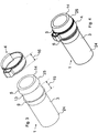
- the hose 1 has a hose end 3, in which the hose 1 ends at an end face 14. In the direction away from the end face 14, the hose 1 extends beyond the hose end piece 3 via a hose section 24, which may have a different length depending on the application and is shown in the figures for the sake of clarity only as a short piece of hose.
- the hose end piece has a mounting area 13 for a hose clamp 4.
- the hose clamp 4 is pushed over the hose end piece 3 into the mounting area 13 and can then be fixed.
- the hose 1 has a hose section 25 projecting beyond the mounting area 13 towards the end face 14, since it is generally desired that the hose clamp is not mounted at the outermost end of the hose end piece 3.
- the hose 1 according to FIG. 1 has in the tube portion 25, which is seen from the end face 14 in front of the mounting portion 13, a protruding on the outside of the tube 1, formed from the tubing thickening 5 on.
- the thickening point 5 is formed radially circumferentially around the outer circumference of the hose end piece 3.
- the thickening point 5 is formed with a taper in the direction of the end face 14, for example in the form of a truncated cone.
- hose clamp 4 is of crimping or crimping type.
- the hose clamp 4 a crimping portion 25 which is pressed together for fastening the hose clamp 4 on the hose 1 with a suitable tool. This reduces the diameter of the hose clamp, which leads to the fixation of the hose on a hose nozzle.
- FIG. 2 1 shows the hose 1 and the hose clamp 4 according to FIG. 1 with the hose clamp 4 already pushed onto the hose 1.
- a hose nozzle 2 is shown, onto which the hose 1 with the hose clamp 4 is to be pushed.
- FIG. 3 shows a further embodiment of a hose 1, in which, in addition to the thickening point 5 in the hose section 25, a further thickening point 6 is arranged in a further away from the end face 14 portion of the hose end piece 3.
- the further thickening point 6 is seen from the front side 14 from behind the mounting portion 13 for the hose clamp 4 is arranged.
- the distance 15 between the thickening points 5, 6 chosen so that it is equal to or slightly larger than the width 16 of the hose clamp 4. This allows the hose clamp 4 without effort in the mounting area 13 between the two thickening points 5, 6 are positioned and becomes prevented by the two thickening points 5, 6 of an undesirable deplacement in both directions in the longitudinal direction of the tube 1.
- FIG. 4 shows the hose 1 and the hose clamp 4 according to FIG. 3 with the hose clamp 4 pushed over the hose 1.
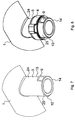
- FIG. 5 shows a further embodiment of a hose 1, in which an annular thickening 7 is formed on the hose end 3, in the mounting portion 13 for the hose clamp 4th
- the hose clamp 4 can be pushed over the thickening point 7 with a slight effort and is kept in the respective position due to the elasticity of the material of the thickening point 7 and the tube 1 by pressing.
- the thickening 7 can, as in the FIG. 5 shown to be formed as a circumferential ring without interruptions.
- the FIG. 6 shows an alternative embodiment of the thickening 7, in which from the outside of the tube 1, a plurality of small fins 8, which are arranged close to each other, protrude.
- the hose 1 is shown here in a plan view of the end face 14, wherein the FIG. 6 only a sector-like section shows.
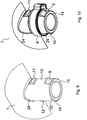
- FIG. 7 shows a further embodiment of a hose 1, in which the hose end 3 branches off at an angle from the hose 1. Furthermore, based on the FIG. 7 a further embodiment of the aforementioned thickening shown, namely two radially opposed thickenings 9, 10, which are arranged starting from the end face 14 in front of the mounting portion 13.
- the thickenings 9, 10 are formed approximately circular sector-like and have a tapered in the longitudinal direction of the hose end 3 profile, so, that, starting from the end face 14, an approximately ramp-like increase in the height of the thickenings 9, 10 results.
- FIG. 8 shows the hose 1 according to FIG. 7 with pushed over the hose end 3 hose clamp. 4
- FIG. 9 shows a further embodiment of a hose.
- further thickening 11, 12 are provided, which, starting from the end face 14, are arranged behind the mounting portion 13.
- the thickenings 11, 12 are formed substantially with the same shape as the thickenings 9, 10, but with their beveled contour in the opposite direction as the thickenings 9, 10th
- FIG. 10 shows the hose 1 according to FIG. 9 with pushed over the hose end 3 hose clamp. 4
- the FIG. 11 shows a hose 1 with a plurality of branch points 17, 18, 19, 20, wherein in the FIG. 11 four branch points are shown, but also more or less branch points are advantageously feasible.
- the branching points 17, 18, 19, 20 each have a hose end piece 3, 21, 22, 23.
- the hose end pieces 3, 21, 22, 23 are formed with thickening points of the type described above, wherein in the FIG. 11 by way of example the embodiment according to FIG FIG. 8 is reproduced. However, the other described embodiments may be provided. About the Schlauchend Publishede 3, 21, 22, 23 respectively hose clamps are pushed.
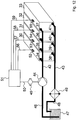
- the FIG. 12 shows a battery assembly for electric or hybrid vehicles.
- the battery assembly has a plurality of battery elements 30, 31, 32, 33, wherein in FIG. 12 four battery elements are shown by way of example, However, more or less battery elements are advantageously possible.
- the battery elements 30, 31, 32, 33 contain a plurality of individual battery cells, which require cooling during operation. For this reason, each battery element 30, 31, 32, 33 has an internal coolant distribution.
- each battery element 30, 31, 32, 33 has its own coolant supply port 34, 35, 36, 37.
- each battery element has a coolant discharge port 38, 39, 40, 41.
- the coolant supply ports and the coolant discharge ports are each formed with a hose nozzle, which is used for mounting a hose for supplying and discharging the coolant.
- the coolant supply ports 34, 35, 36, 37 are via a hose 42 of the type described above, in particular a hose according to FIG. 11 , connected to a coolant source 44, 47.
- the coolant source 44, 47 has, for example, a coolant pump 44 and coolant reservoir 47.
- the hose 42 is connected to the coolant pump 44.
- the coolant pump 44 is again connected on the input side via a further hose 46 to a coolant reservoir 47.
- the coolant discharge ports 38, 39, 40, 41 are connected via a hose 43 of the type described above, in particular a hose according to FIG.
- the coolant sink 47, 49 has, for example, a heat exchanger 49 and the coolant reservoir 47.
- the hose 43 is connected to an input port of the heat exchanger 49.
- the heat exchanger 49 may, for. B. be designed as a cooler.
- the heat exchanger 49 is connected via a further hose 48 with the coolant reservoir 47.
- the battery arrangement according to FIG. 12 also has an electronic control unit 51 which monitors the temperature of the battery elements 30, 31, 32, 33 and controls the cooling liquid pump 44 as a function thereof.
- an electronic control unit 51 which monitors the temperature of the battery elements 30, 31, 32, 33 and controls the cooling liquid pump 44 as a function thereof.
- each of the battery elements 30, 31, 32, 33 with a temperature sensor 52, 53, 54, 55 provided.
- the temperature sensors 52, 53, 54, 55 are connected via respective electrical lines 56, 57, 58, 59 to the electronic control unit 51.
- the electronic control unit 51 is also connected via an electrical line 50 to an electric motor 45.
- the electric motor 45 is connected to the coolant pump 44 via a shaft.
- the electric motor 45 serves to drive the cooling liquid pump 44.
- the electronic control device controls the electric motor 55, z. B. via speed control, such that the battery elements 30, 31, 32, 33 are supplied in sufficient manner with the cooling liquid and the resulting heat is dissipated so far that none of the battery elements 30, 31, 32, 33 is heated in an inadmissible manner.
Landscapes
- Engineering & Computer Science (AREA)
- General Engineering & Computer Science (AREA)
- Chemical & Material Sciences (AREA)
- Chemical Kinetics & Catalysis (AREA)
- Electrochemistry (AREA)
- General Chemical & Material Sciences (AREA)
- Mechanical Engineering (AREA)
- Manufacturing & Machinery (AREA)
- Automation & Control Theory (AREA)
- Supports For Pipes And Cables (AREA)
- Secondary Cells (AREA)
Description
- Die Erfindung betrifft ferner eine Batterieanordnung für Elektro- oder Hybridfahrzeuge.
- Bei der Montage eines Schlauchs auf einem Schlauchstutzen wird häufig eine Schlauchschelle verwendet, um den Schlauch auf dem Schlauchstutzen zu fixieren und eine sichere und dauerhafte Abdichtung zu gewährleisten. Der Arbeitsablauf besteht üblicherweise darin, dass zunächst die Schlauchschelle lose über den Schlauch geschoben wird, ein Schlauchendstück dann über den Schlauchstutzen übergeschoben wird, sodann die Schlauchschelle in einen Montagebereich im Bereich des Schlauchendstückes positioniert und gehalten wird und dann endgültig befestigt wird. Beim Befestigen der Schlauchschelle wird diese zusammengezogen, so dass durch die Schlauchschelle der Schlauch gegen den Schlauchstutzen gepresst wird.
- Eine solche Schlauchschellenbefestigung ist z. B. aus
DE 88 08 680 U1 bekannt. Weitere Schlauchanordnungen sind aus derDE 103 49 527 A1 , derEP 1 338 840 A1 , derDE 195 01 615 A1 , derDE 20 102 973 U1 und derFR 2 595 437 A2 - Der Erfindung liegt die Aufgabe zugrunde, einen Kühlflüssigkeits-Verteilerschlauch anzugeben, mit dem die zuvor beschriebene Montage mittels einer Schlauchschelle vereinfacht wird, wobei eine Batterieanordnung mit einem solchen Schlauch angegeben wird. Diese Aufgabe wird durch die in Anspruch 1 angegebene Erfindung gelöst. Die Unteransprüche geben vorteilhafte Ausgestaltungen der Erfindung an.
- Die Erfindung erleichtert die Montage von Schläuchen mit Schlauchschellen. Vorteilhaft ist, dass das Schlauchendstück durch wenigstens eine von der Außenseite des Schlauchs hervorstehende Verdickungsstelle derart ausgeformt wird, dass die Schlauchschelle vor der endgültigen Fixierung verliersicher aufgesteckt werden kann. Hierdurch wird die Schlauchschelle in der für die Montage richtigen Position gehalten und muss nur noch endgültig fixiert werden, z. B. durch Anziehen einer Spannschraube oder Verbördeln oder Vercrimpen. Die Verdickungsstelle ist dabei derart ausgebildet, dass eine zur Befestigung des Schlauchs auf dem Schlauchstutzen geeignete Schlauchschelle von der Verdickungsstelle wenigstens gegenüber dem Schwerkrafteinfluss, wenn dieser in Längsrichtung des Schlauchendstücks wirksam ist, auf dem Schlauchendstück gehalten wird. Die Verdickungsstelle erlaubt dabei ein Überschieben der Schlauchschelle aufgrund der Elastizität des verwendeten Materials des Schlauchs bzw. der Verdickungsstelle. Auf diese Weise wird die Schlauchschelle zumindest gegenüber dem Einfluss der Schwerkraft sicher an dem Schlauchende gehalten und kann nicht hinunterfallen.
- Die Erfindung wirkt sich insbesondere dann besonders positiv auf Montagezeiten von Schläuchen und die damit verbundenen Kosten aus, wenn eine große Anzahl von Schläuchen bzw. Schlauchendstücken auf jeweiligen Schlauchstutzen zu montieren ist, wie z. B. bei Kühlflüssigkeitssystemen, bei denen eine größere Anzahl von Kühlkreisen über eigene Schlauchstutzen mit dem Schlauch bzw. einer Mehrzahl von Schlauchendstücken verbunden werden muss. Die erfindungsgemäße Anwendung findet sich im Bereich flüssigkeitsgekühlter Batterieanordnungen für Elektro- oder Hybridfahrzeuge. Die Verdickungsstelle kann erfindungsgemäß in vielerlei Ausgestaltungen sehr unterschiedlich ausgeformt sein. Von Bedeutung ist, dass die Verdickungsstelle eine solche Formgebung des Schlauchendstückes zur Folge hat, dass die Schlauchschelle nicht ohne weiteres selbsttätig eine gewünschte Position verlassen kann. Die Verdickungsstelle kann z. B. als eine oder mehrere Noppen- oder Ring-förmige Erhebungen mit gleichmäßiger oder unregelmäßiger Formgebung ausgebildet sein. Die nach außen weisende Oberfläche der Verdickung kann glatt oder mit einer Struktur versehen sein, z. B. genoppt oder genarbt. Es können eine oder mehrere Verdickungsstellen vorgesehen sein.
- Als elastisches Material für den Schlauch kommen grundsätzlich sämtliche elastischen Materialien in Frage, insbesondere gummielastische Materialien und Elastomere, wie z. B. Gummi oder Silikon. Die Verdickungsstelle kann aus dem Schlauchmaterial oder einem anderen geeigneten Material gebildet sein. Die Verdickungsstelle muss nicht zwangsläufig einstückig mit dem Schlauch hergestellt sein. Die Verdickungsstelle kann auch als Einsatzstück in eine Aufnahmestelle des Schlauchendstückes eingesetzt werden. Vorteilhaft ist jedoch eine einstückige Ausbildung der Verdickungsstelle mit dem Schlauch in einem einheitlichen Herstellprozess.
- Die Verdickungsstelle kann durch Hinzufügung zusätzlichen Materials zum Schlauchendstück oder durch lokale Aufweitung des vorhandenen Schlauchmaterials hergestellt werden.
- Gemäß einer vorteilhaften Weiterbildung der Erfindung verläuft die Verdickungsstelle vollständig um den Außenumfang des Schlauchs herum, z. B. in Form eines Rings.
- Gemäß einer vorteilhaften Weiterbildung der Erfindung ist hierbei das Maß, um das die Verdickungsstelle von der Außenseite des Schlauchs hervorsteht, um den Außenumfang des Schlauchs herum gleich bleibend.
- Gemäß einer vorteilhaften Weiterbildung der Erfindung ist die Verdickungsstelle in dem Montagebereich der Schlauchschelle angeordnet. Dies hat den Vorteil, dass schon mit einer einzigen Verdickungsstelle die Schlauchschelle in ihrer endgültigen Montageposition gehalten werden kann. Vorteilhaft ist die Verdickungsstelle vollständig um den Außenumfang des Schlauchs herum verlaufend ausgebildet, z. B. in Ringform. Ebenfalls vorteilhaft ist es, die Verdickungsstelle in Ringform, aber mit Unterbrechungen, auszugestalten. Vorteilhaft ist insbesondere die Ausgestaltung der Verdickungsstelle in Form einer Mehrzahl von um den Außenumfang entlang einer Ringform angeordneten einzelnen Lamellen, die von der Außenseite des Schlauchs hervorstehen.
- Gemäß einer vorteilhaften Weiterbildung der Erfindung sind wenigstens zwei Verdickungsstellen vorgesehen, die jeweils sektorweise um den Außenumfang des Schlauchs herum verlaufen und jeweils den gleichen Abstand zur Stirnseite des Schlauchendstückes aufweisen. In einer weiteren vorteilhaften Weiterbildung sind die Verdickungsstellen in Umfangsrichtung des Schlauchs gleichmäßig voneinander beabstandet. Vorteilhaft können auch mehr als zwei Verdickungsstellen vorgesehen sein, z. B. drei bis acht.
- Gemäß einer vorteilhaften Weiterbildung der Erfindung ist die Verdickungsstelle von der Stirnseite des Schlauchendstückes aus betrachtet vor dem Montagebereich für die Schlauchschelle angeordnet. Dies hat den Vorteil, dass die Schlauchschelle zunächst über die Verdickungsstelle geschoben werden kann und sodann, ohne dass das Risiko des Herunterfallens der Schlauchschelle vom Schlauchendstück besteht, das Schlauchendstück über den Schlauchstutzen geschoben werden kann. Sofern das Schlauchendstück mit einer räumlichen Orientierung erfolgt, bei der die Stirnseite in Schwerkraftrichtung zeigt, liegt die Schlauchschelle auch quasi automatisch an der richtigen Stelle des Schlauchendstückes, nämlich im Montagebereich. Eine weitere manuelle Justierung wird hierdurch entbehrlich. Hierdurch wird insbesondere eine Schlauchmontage bei nach unten weisender Stirnseite des Schlauchendstückes erleichtert.
- Gemäß einer vorteilhaften Weiterbildung der Erfindung ist die Verdickungsstelle von der Stirnseite des Schlauchendstückes aus betrachtet hinter dem Montagebereich für die Schlauchschelle angeordnet. Dies hat den Vorteil, dass durch die Verdickungsstelle ein Wegrutschen der Schlauchschelle in einen von der Stirnseite des Schlauchendstückes weiter fort gelegenen Schlauchabschnitt verhindert wird. Insbesondere bei Vorhandensein einer Schwerkraftkomponente bei der Montage der Schlauchschelle von der Stirnseite fort ergibt sich der Vorteil, dass die Schlauchschelle in ihrer Montageposition im Montagebereich des Schlauchendstückes gehalten wird.
- Ebenfalls vorteilhaft ist es, sowohl eine Verdickungsstelle vor dem Montagebereich als auch eine weitere Verdickungsstelle hinter dem Montagebereich vorzusehen. Hierdurch kann die Schlauchschelle in beiden Richtungen fixiert werden.
- Gemäß einer vorteilhaften Weiterbildung der Erfindung ist wenigstens eine erste Verdickungsstelle von der Stirnseite des Schlauchendstückes aus betrachtet vor dem Montagebereich für die Schlauchschelle angeordnet. Wenigstens eine zweite Verdickungsstelle ist von der Stirnseite des Schlauchendstückes aus betrachtet hinter dem Montagebereich für die Schlauchschelle angeordnet. Der Abstand zwischen der ersten und der zweiten Verdickungsstelle ist gleich oder geringfügig größer als die Breite der Schlauchschelle. Hierdurch wird die Schlauchschelle in einer bestimmten Position fixiert und hat kein oder nur wenig Spiel in Längsrichtung des Schlauchsendstücks.
- Gemäß einer vorteilhaften Weiterbildung der Erfindung nimmt das Maß, um das die Verdickungsstelle von der Außenseite des Schlauchs hervorsteht, in Richtung zur Stirnseite des Schlauchendstückes hin ab. Die Abnahme kann z. B. linear oder bogenförmig verlaufen. Hierdurch wird eine gewisse Schräge der Verdickungsstelle in Richtung zur Stirnseite hin vorgesehen, die das Aufsetzen und Führen der Schlauchschelle über die Verdickungsstelle hinüber bis in den Montagebereich erleichtert.
- Gemäß einer vorteilhaften Weiterbildung der Erfindung ist die Summe aus dem Außendurchmesser des Schlauchendstückes und dem Maß, um das die Verdickungsstelle von der Außenseite des Schlauchs hervorsteht, größer als der Innendurchmesser der Schlauchschelle im unbefestigten Zustand. Als unbefestigter Zustand sei der Lieferzustand der Schlauchschelle verstanden. Dies hat den Vorteil, dass ein sicherer Halt der Schlauchschelle auf dem Schlauchendstück ermöglicht wird.
- Gemäß einer vorteilhaften Weiterbildung der Erfindung verläuft die Verdickungsstelle vollständig um den Außenumfang des Schlauchs herum, weist in Draufsicht auf die Stirnseite des Schlauchendstücks eine kreisrunde Außenkontur auf und hat einen Durchmesser, der größer ist als der Innendurchmesser der Schlauchschelle im unbefestigten Zustand. Dies erlaubt eine einfache Herstellung der Verdickungsstelle.
- Gemäß einer vorteilhaften Weiterbildung der Erfindung liegt das Maß, um das die Verdickungsstelle von der Außenseite des Schlauchs hervorsteht, im Bereich von 1 bis 4 mm. Dies hat den Vorteil, dass der Einsatz von Schlauchschellen mit Normdurchmessern begünstigt wird. Für jeden üblichen Schlauchdurchmesser kann eine geeignete Schlauchschelle mit einem Normdurchmesser ausgewählt werden. Diese lässt sich dann einerseits bequem und beschädigungsfrei über die Verdickungsstelle hinüberschieben und wird außerdem nach dem Hinüberschieben von der Verdickungsstelle gehalten.
- Gemäß der Erfindung weist der Schlauch wenigstens zwei Abzweigungsstellen auf. An den Abzweigungsstellen ist jeweils ein Schlauchabschnitt mit jeweils einem Schlauchendstück angeordnet. Ein solcher Schlauch dient als Verteilerschlauch (Manifold) zur Weiterleitung und Verteilung von Kühlflüssigkeit. Der Schlauch kann insbesondere mit einer größeren Anzahl von Abzweigungsstellen versehen sein, z. B. 6 oder 10. Durch die jeweils an den Schlauchendstücken vorgesehenen Verdickungsstellen wird die Montage eines solchen Schlauchs mittels Schlauchschellen erleichtert und beschleunigt.
- Zusätzlich sind sämtliche zuvor beschriebenen Ausführungsformen des Schlauchs bzw. der Verdickungsstellen vorteilhaft miteinander kombinierbar.
- Die Erfindung betrifft eine Batterieanordnung für Elektro- oder Hybridfahrzeuge mit einer Mehrzahl von einzelnen Batterieelementen, die jeweils einen Kühlmittel-Zufuhranschluss und einen Kühlmittel-Abfuhranschluss aufweisen, wobei die Kühlmittel-Zufuhranschlüsse untereinander und mit einer Kühlmittelquelle über einen Kühlflüssigkeits-Verteilerschlauch der zuvor beschriebenen Art und/oder die Kühlmittel-Abfuhranschlüsse untereinander und mit einem Kühlmittelsenke über einen Kühlflüssigkeits-Verteilerschlauch der zuvor beschriebenen Art verbunden sind. Jedes Batterieelement kann beispielsweise eine Mehrzahl von zylindrischen Rundzellen oder prismatischen Zellen aufweisen.
- Die Erfindung wird nachfolgend anhand von Ausführungsbeispielen unter Verwendung von Zeichnungen näher erläutert.
- Es zeigen:
- Figur 1
- einen Schlauch und eine Schlauchschelle und
- Figur 2
- den Schlauch gemäß
Figur 1 mit aufgesetzter Schlauchschelle und - Figur 3
- eine weitere Ausführungsform eines Schlauchs und eine Schlauchschelle und
- Figur 4
- den Schlauch gemäß
Figur 3 mit aufgesetzter Schlauchschelle und - Figur 5
- eine weitere Ausführungsform eines Schlauchs und eine Schlauchschelle und
- Figur 6
- ein Schlauchsegment im Querschnitt und
- Figur 7
- eine weitere Ausführungsform eines Schlauchs und
- Figur 8
- den Schlauch gemäß
Figur 7 mit aufgesetzter Schlauchschelle und - Figur 9
- eine weitere Ausführungsform eines Schlauchs und
- Figur 10
- den Schlauch gemäß
Figur 9 mit aufgesetzter Schlauchschelle und - Figur 11
- eine erfindungsgemäße Ausführungsform eines Schlauchs mit aufgesetzten Schlauchschellen und
- Figur 12
- eine Batterieanordnung für Elektro- oder Hybridfahrzeuge.
- In den Figuren werden gleiche Bezugszeichen für einander entsprechende Elemente verwendet.
- In der
Figur 1 sind ein Schlauch 1 und eine Schlauchschelle 4 dargestellt. Der Schlauch 1 weist ein Schlauchendstück 3 auf, in dem der Schlauch 1 an einer Stirnfläche 14 endet. In der von der Stirnfläche 14 abgewandten Richtung erstreckt sich der Schlauch 1 jenseits des Schlauchendstückes 3 über einen Schlauchabschnitt 24, der je nach Anwendungsfall eine unterschiedliche Länge aufweisen kann und in den Figuren der besseren Übersicht halber nur als kurzes Schlauchstück dargestellt ist. Das Schlauchendstück weist einen Montagebereich 13 für eine Schlauchschelle 4 auf. Die Schlauchschelle 4 wird über das Schlauchendstück 3 bis in den Montagebereich 13 geschoben und kann dann fixiert werden. Im Allgemeinen weist der Schlauch 1 einen über den Montagebereich 13 zur Stirnfläche 14 hin überstehenden Schlauchabschnitt 25 auf, da in der Regel erwünscht ist, dass die Schlauchschelle nicht am äußersten Ende des Schlauchendstücks 3 montiert wird. - Der Schlauch 1 gemäß
Figur 1 weist in dem Schlauchabschnitt 25, der von der Stirnfläche 14 aus gesehen vor dem Montageabschnitt 13 liegt, eine an der Außenseite des Schlauchs 1 hervorstehende, aus dem Schlauchmaterial gebildete Verdickungsstelle 5 auf. Die Verdickungsstelle 5 ist radial umlaufend um den Außenumfang des Schlauchendstücks 3 ausgebildet. In der dargestellten Ausführungsform ist die Verdickungsstelle 5 mit einer Verjüngung in Richtung zur Stirnseite 14 hin ausgebildet, z.B. in Kegelstumpfform. - Die in
Figur 1 ebenfalls dargestellte Schlauchschelle 4 ist vom Bördel- bzw. Crimp-Typ. Hierfür weist die Schlauchschelle 4 einen Bördelbereich 25 auf, der zum Befestigen der Schlauchschelle 4 auf dem Schlauch 1 mit einem geeigneten Werkzeug zusammengepresst wird.
Hierdurch verringert sich der Durchmesser der Schlauchschelle, was zur Fixierung des Schlauchs auf einem Schlauchstutzen führt. - Die
Figur 2 zeigt den Schlauch 1 sowie die Schlauchschelle 4 gemäß Figur 1 bei auf dem Schlauch 1 bereits aufgeschobener Schlauchschelle 4. Zudem ist ein Schlauchstutzen 2 dargestellt, auf den der Schlauch 1 mit der Schlauchschelle 4 übergeschoben werden soll. - Die
Figur 3 zeigt eine weitere Ausführungsform eines Schlauchs 1, bei der zusätzlich zu der Verdickungsstelle 5 im Schlauchabschnitt 25 noch eine weitere Verdickungsstelle 6 in einem weiter von der Stirnseite 14 fort gelegenen Bereichs des Schlauchendstücks 3 angeordnet ist. Die weitere Verdickungsstelle 6 ist dabei von der Stirnseite 14 aus gesehen hinter dem Montagebereich 13 für die Schlauchschelle 4 angeordnet. Hierbei ist der Abstand 15 zwischen den Verdickungsstellen 5, 6 so gewählt, dass er gleich oder geringfügig größer ist als die Breite 16 der Schlauchschelle 4. Hierdurch kann die Schlauchschelle 4 ohne Mühe in dem Montagebereich 13 zwischen den zwei Verdickungsstellen 5, 6 positioniert werden und wird durch die zwei Verdickungsstellen 5, 6 von einer unerwünschten Deplatzierung in beiden Richtungen in Längsrichtung des Schlauchs 1 gehindert. - Die
Figur 4 zeigt den Schlauch 1 sowie die Schlauchschelle 4 gemäß Figur 3 bei über den Schlauch 1 geschobener Schlauchschelle 4. - Die
Figur 5 zeigt eine weitere Ausführungsform eines Schlauchs 1, bei dem eine ringförmig ausgebildete Verdickung 7 an dem Schlauchendstück 3 ausgebildet ist, und zwar in dem Montagebereich 13 für die Schlauchschelle 4. - Die Schlauchschelle 4 kann dabei mit leichtem Kraftaufwand über die Verdickungsstelle 7 geschoben werden und wird aufgrund der Elastizität des Materials der Verdickungsstelle 7 sowie des Schlauchs 1 durch Pressung in der jeweiligen Position gehalten.
- Die Verdickung 7 kann, wie in der
Figur 5 dargestellt, als umlaufender Ring ohne Unterbrechungen ausgebildet sein. DieFigur 6 zeigt eine alternative Ausgestaltung der Verdickungsstelle 7, bei der von der Außenseite des Schlauchs 1 eine Vielzahl von kleinen Lamellen 8, die dicht nebeneinander angeordnet sind, abstehen. Der Schlauch 1 ist hierbei in einer Draufsicht auf die Stirnfläche 14 dargestellt, wobei dieFigur 6 nur einen sektorartigen Ausschnitt zeigt. - Die
Figur 7 zeigt eine weitere Ausführungsform eines Schlauchs 1, bei dem das Schlauchendstück 3 in einen Winkel von dem Schlauch 1 abzweigt. Des Weiteren wird anhand derFigur 7 eine weitere Ausführungsform der erwähnten Verdickungen dargestellt, nämlich zwei radial einander gegenüberliegende Verdickungen 9, 10, die ausgehend von der Stirnfläche 14 vor dem Montagebereich 13 angeordnet sind. Die Verdickungen 9, 10 sind etwa kreissektorartig ausgebildet und weisen ein in Längsrichtung des Schlauchendstücks 3 verjüngend verlaufendes Profil auf, derart, dass sich, ausgehend von der Stirnfläche 14, ein etwa rampenartiger Anstieg der Bauhöhe der Verdickungen 9, 10 ergibt. - Die
Figur 8 zeigt den Schlauch 1 gemäßFigur 7 mit über das Schlauchendstück 3 geschobener Schlauchschelle 4. - Die
Figur 9 zeigt eine weitere Ausführungsform eines Schlauchs. Im Unterschied zurFigur 7 sind außer den Verdickungen 9, 10 im Schlauchabschnitt 25 des Schlauchendstückes 3 weitere Verdickungen 11, 12 vorgesehen, die, ausgehend von der Stirnfläche 14, hinter dem Montagebereich 13 angeordnet sind. Die Verdickungen 11, 12 sind im Wesentlichen mit gleicher Formgebung wie die Verdickungen 9, 10 ausgebildet, weisen jedoch mit ihrer abgeschrägten Kontur in die entgegengesetzte Richtung wie die Verdickungen 9, 10. - Die
Figur 10 zeigt den Schlauch 1 gemäßFigur 9 mit über das Schlauchendstück 3 geschobener Schlauchschelle 4. - Die
Figur 11 zeigt einen Schlauch 1 mit einer Mehrzahl von Abzweigungsstellen 17, 18, 19, 20, wobei in derFigur 11 vier Abzweigungsstellen dargestellt sind, jedoch auch mehr oder weniger Abzweigungsstellen vorteilhaft realisierbar sind. Die Abzweigungsstellen 17, 18, 19, 20 weisen jeweils ein Schlauchendstück 3, 21, 22, 23 auf. Die Schlauchendstücke 3, 21, 22, 23 sind mit Verdickungsstellen der zuvor beschriebenen Art ausgebildet, wobei in derFigur 11 beispielhaft die Ausführungsform gemäßFigur 8 wiedergegeben ist. Jedoch können auch die anderen beschriebenen Ausführungsformen vorgesehen werden. Über die Schlauchendstücke 3, 21, 22, 23 sind jeweils Schlauchschellen geschoben. - Die
Figur 12 zeigt eine Batterieanordnung für Elektro- oder Hybridfahrzeuge. Die Batterieanordnung weist mehrere Batterieelemente 30, 31, 32, 33 auf, wobei inFigur 12 beispielhaft vier Batterieelemente dargestellt sind, jedoch auch mehr oder weniger Batterieelemente vorteilhaft möglich sind. Die Batterieelemente 30, 31, 32, 33 enthalten eine Mehrzahl von einzelnen Batteriezellen, die im Betrieb der Kühlung bedürfen. Aus diesem Grunde weist jedes Batterieelement 30, 31, 32, 33 eine interne Kühlmittelverteilung auf. Für die Zufuhr des Kühlmittels weist jedes Batterieelement 30, 31, 32, 33 einen eigenen Kühlmittel-Zufuhranschluss 34, 35, 36, 37 auf. Für die Abfuhr des durch das jeweilige Batterieelement 30, 31, 32, 33 geflossenen Kühlmittels weist jedes Batterieelement einen Kühlmittel-Abfuhranschluss 38, 39, 40, 41 auf. Die Kühlmittel-Zufuhranschlüsse sowie die Kühlmittel-Abfuhranschlüsse sind jeweils mit einem Schlauchstutzen ausgebildet, der für die Montage eines Schlauchs zur Zufuhr und Abfuhr des Kühlmittels dient. Die Kühlmittel-Zufuhranschlüsse 34, 35, 36, 37 sind über einen Schlauch 42 der zuvor beschriebenen Art, insbesondere einem Schlauch gemäßFigur 11 , mit einer Kühlmittelquelle 44, 47 verbunden. Die Kühlmittelquelle 44, 47 weist z.B. eine Kühlflüssigkeitspumpe 44 und Kühlflüssigkeitsvorratsbehälter 47 auf. Der Schlauch 42 ist dabei an die Kühlflüssigkeitspumpe 44 angeschlossen. Die Kühlflüssigkeitspumpe 44 ist eingangsseitig wiederum über einen weiteren Schlauch 46 mit einem Kühlflüssigkeitsvorratsbehälter 47 verbunden. Die Kühlmittel-Abfuhranschlüsse 38, 39, 40, 41 sind über einen Schlauch 43 der zuvor beschriebenen Art, insbesondere einem Schlauch gemäßFigur 11 , mit einer Kühlmittelsenke 47, 49 verbunden. Die Kühlmittelsenke 47, 49 weist z.B. einen Wärmetauscher 49 und den Kühlflüssigkeitsvorratsbehälter 47 auf. Der Schlauch 43 ist dabei mit einem Eingangsanschluss des Wärmetauschers 49 verbunden. Der Wärmetauscher 49 kann z. B. als Kühler ausgebildet sein. Ausgangsseitig ist der Wärmetauscher 49 über einen weiteren Schlauch 48 mit dem Kühlflüssigkeitsbehälter 47 verbunden. - Die Batterieanordnung gemäß
Figur 12 weist zudem ein elektronisches Steuergerät 51 auf, das die Temperatur der Batterieelemente 30, 31, 32, 33 überwacht und hiervon abhängig die Kühlflüssigkeitspumpe 44 steuert. Hierfür ist jedes der Batterieelemente 30, 31, 32, 33 mit einem Temperatursensor 52, 53, 54, 55 versehen. - Die Temperatursensoren 52, 53, 54, 55 sind über jeweilige elektrische Leitungen 56, 57, 58, 59 mit dem elektronischen Steuergerät 51 verbunden. Das elektronische Steuergerät 51 ist außerdem über eine elektrische Leitung 50 mit einem Elektromotor 45 verbunden. Der Elektromotor 45 ist über eine Welle mit der Kühlflüssigkeitspumpe 44 verbunden. Der Elektromotor 45 dient zum Antrieb der Kühlflüssigkeitspumpe 44. Die elektronische Steuereinrichtung steuert den Elektromotor 55, z. B. über Drehzahlregelung, derart, dass die Batterieelemente 30, 31, 32, 33 in ausreichender Weise mit der Kühlflüssigkeit versorgt werden und die entstehende Wärme soweit abgeführt wird, dass keines der Batterieelemente 30, 31, 32, 33 sich in unzulässiger Weise erwärmt.
Claims (11)
- Batterieanordnung für Elektro- oder Hybridfahrzeuge mit einer Mehrzahl von einzelnen Batterieelementen (30, 31, 32, 33), die jeweils einen Kühlmittel-Zufuhranschluss (34, 35, 36, 37) und einen Kühlmittel-Abfuhranschluss 2. (38, 39, 40, 41) aufweisen, wobei die Kühlmittel-Zufuhranschlüsse (34, 35, 36, 37) untereinander und mit einer Kühlmittelquelle (44, 47) über einen Kühlflüssigkeits-Verteilerschlauch (42) und/oder die Kühlmittel-Abfuhranschlüsse (38, 39, 40, 41) untereinander und mit einem Kühlmittelsenke (47, 49) über einen Kühlflüssigkeits-Verteilerschlauch (43) verbunden sind, wobei der Kühlflüssigkeits-Verteilerschlauch (42, 43) aus einem elastischen Material besteht und wenigstens zwei Abzweigungsstellen (17, 18, 19, 20) aufweist, an denen jeweils ein Schlauchabschnitt mit jeweils einem Schlauchendstück (3, 21, 22, 23) angeordnet ist, wobei jeder Schlauchabschitt jeweils zur Montage auf einem Schlauchstutzen (2) durch Überschieben eines Schlauchendstücks (3) des Schlauchs (1) über den Schlauchstutzen (2) und zur Befestigung auf dem Schlauchstutzen (2) durch eine in einem Montagebereich (13) des Schlauchendstücks (3) anzuordnende Schlauschelle (4) ausgebildet ist, wobei jedes Schlauchendstück (3) jeweils wenigstens eine von der Außenseite des Schlauchendstücks (3) hervorstehende Verdickungsstelle (5, 6, 7, 8, 9, 10, 11, 12) aufweist, die wenigstens soweit von der Außenseite des Schaluchendstücks (3) hervorsteht, dass die zur Befestigung des Schlauchendstücks (3) auf dem Schlauchstutzen (2) geeignete Schlauchschelle (4) von der Verdickungsstelle (5, 6, 7, 8, 9, 10, 11, 12) gegenüber dem Schwerkrafteinfluss, wenn diese in Längsrichtung des Schlauchendstücks (3) wirksam ist, auf dem Schlauchendstück (3) gehalten ist.
- Batterieanordnung nach Anspruch 1,
dadurch gekennzeichnet, dass
die Verdickungsstelle(5, 6, 7, 8, 9, 10, 11, 12) vollständig um den Außenumfang des Schlauchendstücks (3) herum verläuft. - Batterieanordnung nach einem der vorhergehenden Ansprüche,
dadurch gekennzeichnet, dass
die Verdickungsstelle (5, 6, 7, 8, 9, 10, 11, 12) in dem Montagebereich (13) für Schlauchschelle (4) angeordnet ist. - Batterieanordnung nach einem der vorhergehenden Ansprüchen,
dadurch gekennzeichnet, dass
wenigstens zwei Verdickungsstellen (5, 6, 7, 8, 9, 10, 11, 12) vorgesehen sind, jeweils sektorweise um den Außenumfang des Schlauchendstücks (3) herum verlaufen und jeweils den gleichen Abstand zur Stirnseite (14) des Schlauchendstücks (3) aufweisen. - Batterieanordnung nach einem der vorhergehenden Ansprüche,
dadurch gekennzeichnet, dass
die Verdickungsstelle (5, 6, 7, 8, 9, 10, 11, 12) von der Stirnseite (14) des Schlauchendstücks (3) aus betrachtet vor dem Montagebereich (13) für die Schlauchschelle (4) angeordnet ist. - Batterieanordnung nach einem der vorhergehenden Ansprüche,
dadurch gekennzeichnet, dass
die Verdickungsstelle (5, 6, 7, 8, 9, 10, 11, 12) von der Stirnseite (14) des Schlauendstücks (3) aus betrachtet hinter dem Montagebereich (13) für die Schlauchschelle (4) angeordnet ist. - Batterieanordnung nach einem der vorhergehenden Ansprüche,
dadurch gekennzeichnet, dass
wenigstens eine erste Verdickungsstelle (5, 9, 10) von der Stirnseite (14) des Schlauchendstücks (3) aus betrachtet vor dem Montagebereich (13) für die Schlauchschelle (4) angeordnet ist und wenigsten eine zweite Verdickungsstelle (6, 11, 12) von der Stirnseite (14) des Schlauchendstücks (3) aus betrachtet hinter dem Montagebereich (13) für die Schlauchschelle (4) angeordnet ist, wobei der Abstand (15) zwischen der ersten und der zweiten Verdickungsstelle (5, 6, 7, 8, 9, 10, 11, 12) gleich oder geringfügig größer ist als die Breite (16) der Schlauchschelle (4). - Batterieanordnung nach einem der vorhergehenden Ansprüche,
dadurch gekennzeichnet, dass
das Maß, um das die Verdickungsstelle (5, 6, 7, 8, 9, 10, 11, 12) von der Außenseite des Schlauchendstücks (3) hervorsteht, in Richtung zur Stirnseite (14) des Schlauchendstücks (3) hin abnimmt. - Batterieanordnung nach einem der vorhergehenden Ansprüche,
dadurch gekennzeichnet, dass
die Summe aus dem Außendurchmesser des Schlauchendstücks (3) und dem Maß, um das die Verdickungsstelle (5, 6, 7, 8, 9, 10, 11, 12) von der Außenseite des Schlauchendstücks (3) hervorsteht, größer ist als der Innendurchmesser der Schlauchschelle (4) im unbefestigten Zustand. - Batterieanordnung nach einem der vorhergehenden Ansprüche,
dadurch gekennzeichnet, dass
die Verdickungsstelle (5, 6, 7, 8, 9, 10, 11, 12) vollständig um den Außenumfang des Schlauchendstücks (3) herum verläuft, in Draufsicht auf die Stirnseite (14) des Schlauchendstücks (3) eine kreisrunde Außenkontur aufweist und einen Durchmesser hat, der größer ist als der Innendurchmesser der Schlauchschelle (4) im unbefestigten Zustand. - Batterieanordnung nach einem der vorhergehenden Ansprüche,
dadurch gekennzeichnet, dass
das Maß, um das die Verdickungsstelle (5, 6, 7, 8, 9, 10, 11, 12) von den Außenseiten des Schlauchendstücks (3) hervorsteht, im Bereich von 1 bis 4 mm liegt.
Applications Claiming Priority (2)
| Application Number | Priority Date | Filing Date | Title |
|---|---|---|---|
| DE201010049015 DE102010049015B4 (de) | 2010-10-21 | 2010-10-21 | Kühlflüssigkeits-Verteilerschlauch und Batterieanordnung |
| PCT/EP2011/005113 WO2012052129A1 (de) | 2010-10-21 | 2011-10-12 | Schlauch aus einem elastischen material |
Publications (2)
| Publication Number | Publication Date |
|---|---|
| EP2630397A1 EP2630397A1 (de) | 2013-08-28 |
| EP2630397B1 true EP2630397B1 (de) | 2017-12-20 |
Family
ID=45531350
Family Applications (1)
| Application Number | Title | Priority Date | Filing Date |
|---|---|---|---|
| EP11770704.2A Active EP2630397B1 (de) | 2010-10-21 | 2011-10-12 | Batterieanordnung mit einem kühlflüssigkeits-verteilerschlauch |
Country Status (5)
| Country | Link |
|---|---|
| US (2) | US20130216889A1 (de) |
| EP (1) | EP2630397B1 (de) |
| CN (1) | CN103270356B (de) |
| DE (1) | DE102010049015B4 (de) |
| WO (1) | WO2012052129A1 (de) |
Cited By (1)
| Publication number | Priority date | Publication date | Assignee | Title |
|---|---|---|---|---|
| US11721856B2 (en) | 2018-10-12 | 2023-08-08 | Samsung Sdi Co., Ltd. | Battery pack for a vehicle |
Families Citing this family (11)
| Publication number | Priority date | Publication date | Assignee | Title |
|---|---|---|---|---|
| US8974934B2 (en) * | 2012-08-16 | 2015-03-10 | Lg Chem, Ltd. | Battery module |
| MX361454B (es) * | 2013-08-14 | 2018-12-06 | Oetiker Schweiz Ag | Abrazadera de oreja. |
| USD755938S1 (en) * | 2014-06-27 | 2016-05-10 | Eaton Corporation | Sensor enclosure assembly for a hose |
| USD739506S1 (en) * | 2014-06-27 | 2015-09-22 | Eaton Corporation | Sensor enclosure assembly for a hose |
| DE102017203206B4 (de) | 2017-02-28 | 2023-02-02 | Bayerische Motoren Werke Aktiengesellschaft | Batterie für einen Kraftwagen und Kraftwagen |
| DE102017208617A1 (de) * | 2017-05-22 | 2018-11-22 | Bayerische Motoren Werke Aktiengesellschaft | Energiespeichergehäuse mit einem Kühlungsanschluss, Energiespeicher und Kraftfahrzeug mit einem solchen |
| FR3080166B1 (fr) * | 2018-04-16 | 2021-01-15 | Coutier Moulage Gen Ind | Rampe distributrice-collectrice de fluide |
| DE202020100325U1 (de) | 2020-01-22 | 2020-02-04 | TI Automotive (Fuldabrück) GmbH | Hitzebeständige, mehrschichtige Fluidleitung |
| EP4170777A1 (de) * | 2021-10-21 | 2023-04-26 | Rimac Automobiles Ltd. | Durchflussbegrenzer |
| US12191518B2 (en) * | 2022-04-05 | 2025-01-07 | GM Global Technology Operations LLC | Active thermal management systems with multi-purpose reservoirs for liquid immersion cooled battery assemblies |
| CN115342250A (zh) * | 2022-09-20 | 2022-11-15 | 安徽舟之航电池有限公司 | 一种应用于新能源电池包内且集成温度传感器的软管总成 |
Citations (2)
| Publication number | Priority date | Publication date | Assignee | Title |
|---|---|---|---|---|
| DE3030134A1 (de) * | 1980-08-08 | 1982-02-25 | Metzeler Kautschuk GmbH, 8000 München | Kuehlwasserschlauch fuer kraftfahrzeuge und verfahren zu seiner herstellung |
| DE3413632A1 (de) * | 1983-04-18 | 1984-10-18 | Dunlop Ltd., London | Verzweigter schlauch |
Family Cites Families (24)
| Publication number | Priority date | Publication date | Assignee | Title |
|---|---|---|---|---|
| US3851646A (en) * | 1973-04-13 | 1974-12-03 | Sarns Inc | Connector for open heart surgery |
| FR2595437B2 (fr) * | 1981-06-01 | 1988-12-02 | Hutchinson | Raccord de derivation sur tuyau souple et son procede de pose |
| DE8808680U1 (de) | 1988-07-06 | 1988-08-25 | Hans Oetiker AG, 8812 Horgen | Schlauchklemme |
| DE3824792A1 (de) * | 1988-07-21 | 1990-01-25 | Porsche Ag | Luftansaugtrakt einer brennkraftmaschine |
| WO1994000286A1 (fr) * | 1992-06-29 | 1994-01-06 | Tokai Rubber Industries, Ltd. | Structure de raccordement pour conduite souple en resine |
| DE19501615A1 (de) * | 1995-01-20 | 1996-08-08 | Porsche Ag | Rohrelement aus elastischem Material |
| DE19602907A1 (de) * | 1996-01-27 | 1997-07-31 | Bosch Gmbh Robert | Befestigungsanordnung einer Kraftstoffleitung auf einem Stutzen |
| CA2240926C (en) * | 1997-06-23 | 2007-09-25 | Hans Oetiker Ag Maschinen - Und Apparatefabrik | Mounting arrangement of partially tightened clamp structure on hose-like member |
| JP4123541B2 (ja) * | 1997-07-02 | 2008-07-23 | 株式会社デンソー | 電池冷却装置 |
| DE60138858D1 (de) * | 2000-08-07 | 2009-07-16 | Tokai Rubber Ind Ltd | Kraftstoffschlauch- Anschlussstruktur und Kraftstoffschlauch |
| DE10107938C2 (de) * | 2001-02-07 | 2003-05-28 | Muendener Gummiwerk Gmbh | Elastomerschlauch für Kraftfahrzeuge, z.B. Turboladerschlauch |
| US6550815B2 (en) * | 2001-08-14 | 2003-04-22 | Itt Manufacturing Enterprises, Inc. | Coaxial quick connector |
| JP4089409B2 (ja) * | 2002-02-22 | 2008-05-28 | 東海ゴム工業株式会社 | 燃料ホース、燃料ホース接続方法及び燃料ホース接続構造体 |
| DE10249474A1 (de) * | 2002-10-24 | 2004-05-13 | Rasmussen Gmbh | Verbindung einer Schelle mit einem Schlauch zur Vorpositionierung der Schelle |
| DE10349527B4 (de) * | 2003-10-22 | 2009-04-23 | Veritas Ag | Schlauch und Schellenfixierung für diesen Schlauch |
| JP2005282820A (ja) * | 2004-03-30 | 2005-10-13 | Tokai Rubber Ind Ltd | 低透過性弾性シールリング |
| JP4428111B2 (ja) * | 2004-03-30 | 2010-03-10 | 東海ゴム工業株式会社 | 流体輸送用ホースの接続構造 |
| JP4582316B2 (ja) * | 2005-02-23 | 2010-11-17 | 東海ゴム工業株式会社 | ホースクランプの保持構造 |
| US7596835B2 (en) * | 2005-08-12 | 2009-10-06 | Fluiding Routing Solutions, Inc. | Hose clamp for a hose and assembly |
| US7503589B2 (en) * | 2005-10-14 | 2009-03-17 | Mann & Hummel Gmbh | Connector assembly and method for connecting hoses |
| US7846573B2 (en) * | 2007-06-01 | 2010-12-07 | Cobasys, Llc | Coolant manifold |
| US20090023056A1 (en) * | 2007-07-18 | 2009-01-22 | Tesla Motors, Inc. | Battery pack thermal management system |
| KR101057556B1 (ko) * | 2010-02-03 | 2011-08-17 | 에스비리모티브 주식회사 | 배터리 시스템 및 그 구동 방법 |
| US20120286506A1 (en) * | 2011-05-10 | 2012-11-15 | Mckenzie Daniel | Water manifold |
-
2010
- 2010-10-21 DE DE201010049015 patent/DE102010049015B4/de not_active Expired - Fee Related
-
2011
- 2011-10-12 EP EP11770704.2A patent/EP2630397B1/de active Active
- 2011-10-12 WO PCT/EP2011/005113 patent/WO2012052129A1/de not_active Ceased
- 2011-10-12 US US13/880,685 patent/US20130216889A1/en not_active Abandoned
- 2011-10-12 CN CN201180062231.XA patent/CN103270356B/zh active Active
-
2017
- 2017-03-30 US US15/474,962 patent/US10804579B2/en active Active
Patent Citations (2)
| Publication number | Priority date | Publication date | Assignee | Title |
|---|---|---|---|---|
| DE3030134A1 (de) * | 1980-08-08 | 1982-02-25 | Metzeler Kautschuk GmbH, 8000 München | Kuehlwasserschlauch fuer kraftfahrzeuge und verfahren zu seiner herstellung |
| DE3413632A1 (de) * | 1983-04-18 | 1984-10-18 | Dunlop Ltd., London | Verzweigter schlauch |
Cited By (1)
| Publication number | Priority date | Publication date | Assignee | Title |
|---|---|---|---|---|
| US11721856B2 (en) | 2018-10-12 | 2023-08-08 | Samsung Sdi Co., Ltd. | Battery pack for a vehicle |
Also Published As
| Publication number | Publication date |
|---|---|
| WO2012052129A1 (de) | 2012-04-26 |
| US20130216889A1 (en) | 2013-08-22 |
| DE102010049015B4 (de) | 2013-12-05 |
| EP2630397A1 (de) | 2013-08-28 |
| CN103270356A (zh) | 2013-08-28 |
| US20170207505A1 (en) | 2017-07-20 |
| DE102010049015A1 (de) | 2012-04-26 |
| US10804579B2 (en) | 2020-10-13 |
| CN103270356B (zh) | 2018-10-02 |
Similar Documents
| Publication | Publication Date | Title |
|---|---|---|
| EP2630397B1 (de) | Batterieanordnung mit einem kühlflüssigkeits-verteilerschlauch | |
| EP2649689B1 (de) | Vorrichtung zur fixierung eines kabels an einem kabelabgangsstutzen | |
| EP2919343B1 (de) | Einbau-Gehäuse zur Aufnahme und Befestigung einer elektrischen Komponente und Gegenstand mit einem derartigen Einbau-Gehäuse sowie Verfahren zur Befestigung eines derartigen Einbau-Gehäuses an einem Gegenstand | |
| EP2610506A1 (de) | Federmutter | |
| EP3321519A1 (de) | Einrichtung zum verbinden zweier bauteile | |
| DE2017322A1 (de) | Zugentlastungsklemme | |
| EP2163801A1 (de) | Schellenfixierung | |
| DE69619362T2 (de) | Spritzgiesssystem und Erhitzungsaufbau zur Verwendung in einem derartigen System | |
| DE102009006294B4 (de) | Schlauchklemme | |
| EP3300088A2 (de) | Verspannvorrichtung für einen überspannungsableiter, herstellungsverfahren und überspannungsableiter | |
| DE102014005775A1 (de) | Batteriepolklemme | |
| DE19728452A1 (de) | Spritzgußverteiler mit Schmelze-Verbindungsbuchsen | |
| EP2518849B1 (de) | Gehäusedurchführung (kabelverschraubung) | |
| EP2664042B1 (de) | Vorrichtung zur fixierung eines kabels an einen kabelabgangsstutzen | |
| DE112016002698T5 (de) | Trommel eines Einlagentyps | |
| DE102019202253A1 (de) | Kühlmittelleitelement, Kühlsystem und elektrische Maschine | |
| DE102023126089A1 (de) | "Fluidverteileranordnung eines Temperierkreislaufes" | |
| DE102013103534B4 (de) | "Steckverbindungsteil für einen Leitungsverbinder, insbesondere für eine konfektionierte Medienleitung" | |
| DE102021212894A1 (de) | Elektrische Maschine, insbesondere elektrische Maschine für ein Kraftfahrzeug | |
| DE102017102052B4 (de) | Steckverbindungsanordnung und Verfahren zur Montage einer Steckverbindungsanordnung | |
| DE102019128040A1 (de) | Steckverbinder | |
| EP2696093B1 (de) | Reibbelagsverschleißsensor | |
| EP3885625B1 (de) | Wellrohrverbindungsanordnung | |
| EP2194308B1 (de) | Kupplungsstück für Wellenschlauch-Anschlussteile | |
| DE102012201133B3 (de) | Fitting |
Legal Events
| Date | Code | Title | Description |
|---|---|---|---|
| PUAI | Public reference made under article 153(3) epc to a published international application that has entered the european phase |
Free format text: ORIGINAL CODE: 0009012 |
|
| 17P | Request for examination filed |
Effective date: 20130419 |
|
| AK | Designated contracting states |
Kind code of ref document: A1 Designated state(s): AL AT BE BG CH CY CZ DE DK EE ES FI FR GB GR HR HU IE IS IT LI LT LU LV MC MK MT NL NO PL PT RO RS SE SI SK SM TR |
|
| DAX | Request for extension of the european patent (deleted) | ||
| 17Q | First examination report despatched |
Effective date: 20140403 |
|
| GRAP | Despatch of communication of intention to grant a patent |
Free format text: ORIGINAL CODE: EPIDOSNIGR1 |
|
| STAA | Information on the status of an ep patent application or granted ep patent |
Free format text: STATUS: GRANT OF PATENT IS INTENDED |
|
| INTG | Intention to grant announced |
Effective date: 20170630 |
|
| GRAS | Grant fee paid |
Free format text: ORIGINAL CODE: EPIDOSNIGR3 |
|
| GRAA | (expected) grant |
Free format text: ORIGINAL CODE: 0009210 |
|
| STAA | Information on the status of an ep patent application or granted ep patent |
Free format text: STATUS: THE PATENT HAS BEEN GRANTED |
|
| AK | Designated contracting states |
Kind code of ref document: B1 Designated state(s): AL AT BE BG CH CY CZ DE DK EE ES FI FR GB GR HR HU IE IS IT LI LT LU LV MC MK MT NL NO PL PT RO RS SE SI SK SM TR |
|
| REG | Reference to a national code |
Ref country code: GB Ref legal event code: FG4D Free format text: NOT ENGLISH |
|
| REG | Reference to a national code |
Ref country code: CH Ref legal event code: EP |
|
| REG | Reference to a national code |
Ref country code: IE Ref legal event code: FG4D Free format text: LANGUAGE OF EP DOCUMENT: GERMAN |
|
| REG | Reference to a national code |
Ref country code: AT Ref legal event code: REF Ref document number: 956692 Country of ref document: AT Kind code of ref document: T Effective date: 20180115 |
|
| REG | Reference to a national code |
Ref country code: DE Ref legal event code: R096 Ref document number: 502011013479 Country of ref document: DE |
|
| REG | Reference to a national code |
Ref country code: NL Ref legal event code: MP Effective date: 20171220 |
|
| PG25 | Lapsed in a contracting state [announced via postgrant information from national office to epo] |
Ref country code: NO Free format text: LAPSE BECAUSE OF FAILURE TO SUBMIT A TRANSLATION OF THE DESCRIPTION OR TO PAY THE FEE WITHIN THE PRESCRIBED TIME-LIMIT Effective date: 20180320 Ref country code: FI Free format text: LAPSE BECAUSE OF FAILURE TO SUBMIT A TRANSLATION OF THE DESCRIPTION OR TO PAY THE FEE WITHIN THE PRESCRIBED TIME-LIMIT Effective date: 20171220 Ref country code: SE Free format text: LAPSE BECAUSE OF FAILURE TO SUBMIT A TRANSLATION OF THE DESCRIPTION OR TO PAY THE FEE WITHIN THE PRESCRIBED TIME-LIMIT Effective date: 20171220 Ref country code: LT Free format text: LAPSE BECAUSE OF FAILURE TO SUBMIT A TRANSLATION OF THE DESCRIPTION OR TO PAY THE FEE WITHIN THE PRESCRIBED TIME-LIMIT Effective date: 20171220 |
|
| REG | Reference to a national code |
Ref country code: LT Ref legal event code: MG4D |
|
| PG25 | Lapsed in a contracting state [announced via postgrant information from national office to epo] |
Ref country code: HR Free format text: LAPSE BECAUSE OF FAILURE TO SUBMIT A TRANSLATION OF THE DESCRIPTION OR TO PAY THE FEE WITHIN THE PRESCRIBED TIME-LIMIT Effective date: 20171220 Ref country code: RS Free format text: LAPSE BECAUSE OF FAILURE TO SUBMIT A TRANSLATION OF THE DESCRIPTION OR TO PAY THE FEE WITHIN THE PRESCRIBED TIME-LIMIT Effective date: 20171220 Ref country code: GR Free format text: LAPSE BECAUSE OF FAILURE TO SUBMIT A TRANSLATION OF THE DESCRIPTION OR TO PAY THE FEE WITHIN THE PRESCRIBED TIME-LIMIT Effective date: 20180321 Ref country code: BG Free format text: LAPSE BECAUSE OF FAILURE TO SUBMIT A TRANSLATION OF THE DESCRIPTION OR TO PAY THE FEE WITHIN THE PRESCRIBED TIME-LIMIT Effective date: 20180320 Ref country code: LV Free format text: LAPSE BECAUSE OF FAILURE TO SUBMIT A TRANSLATION OF THE DESCRIPTION OR TO PAY THE FEE WITHIN THE PRESCRIBED TIME-LIMIT Effective date: 20171220 |
|
| PG25 | Lapsed in a contracting state [announced via postgrant information from national office to epo] |
Ref country code: NL Free format text: LAPSE BECAUSE OF FAILURE TO SUBMIT A TRANSLATION OF THE DESCRIPTION OR TO PAY THE FEE WITHIN THE PRESCRIBED TIME-LIMIT Effective date: 20171220 |
|
| PG25 | Lapsed in a contracting state [announced via postgrant information from national office to epo] |
Ref country code: ES Free format text: LAPSE BECAUSE OF FAILURE TO SUBMIT A TRANSLATION OF THE DESCRIPTION OR TO PAY THE FEE WITHIN THE PRESCRIBED TIME-LIMIT Effective date: 20171220 Ref country code: EE Free format text: LAPSE BECAUSE OF FAILURE TO SUBMIT A TRANSLATION OF THE DESCRIPTION OR TO PAY THE FEE WITHIN THE PRESCRIBED TIME-LIMIT Effective date: 20171220 Ref country code: CZ Free format text: LAPSE BECAUSE OF FAILURE TO SUBMIT A TRANSLATION OF THE DESCRIPTION OR TO PAY THE FEE WITHIN THE PRESCRIBED TIME-LIMIT Effective date: 20171220 Ref country code: CY Free format text: LAPSE BECAUSE OF FAILURE TO SUBMIT A TRANSLATION OF THE DESCRIPTION OR TO PAY THE FEE WITHIN THE PRESCRIBED TIME-LIMIT Effective date: 20171220 Ref country code: SK Free format text: LAPSE BECAUSE OF FAILURE TO SUBMIT A TRANSLATION OF THE DESCRIPTION OR TO PAY THE FEE WITHIN THE PRESCRIBED TIME-LIMIT Effective date: 20171220 |
|
| PG25 | Lapsed in a contracting state [announced via postgrant information from national office to epo] |
Ref country code: RO Free format text: LAPSE BECAUSE OF FAILURE TO SUBMIT A TRANSLATION OF THE DESCRIPTION OR TO PAY THE FEE WITHIN THE PRESCRIBED TIME-LIMIT Effective date: 20171220 Ref country code: IS Free format text: LAPSE BECAUSE OF FAILURE TO SUBMIT A TRANSLATION OF THE DESCRIPTION OR TO PAY THE FEE WITHIN THE PRESCRIBED TIME-LIMIT Effective date: 20180420 Ref country code: SM Free format text: LAPSE BECAUSE OF FAILURE TO SUBMIT A TRANSLATION OF THE DESCRIPTION OR TO PAY THE FEE WITHIN THE PRESCRIBED TIME-LIMIT Effective date: 20171220 Ref country code: PL Free format text: LAPSE BECAUSE OF FAILURE TO SUBMIT A TRANSLATION OF THE DESCRIPTION OR TO PAY THE FEE WITHIN THE PRESCRIBED TIME-LIMIT Effective date: 20171220 |
|
| REG | Reference to a national code |
Ref country code: DE Ref legal event code: R097 Ref document number: 502011013479 Country of ref document: DE |
|
| PG25 | Lapsed in a contracting state [announced via postgrant information from national office to epo] |
Ref country code: MT Free format text: LAPSE BECAUSE OF FAILURE TO SUBMIT A TRANSLATION OF THE DESCRIPTION OR TO PAY THE FEE WITHIN THE PRESCRIBED TIME-LIMIT Effective date: 20171220 |
|
| REG | Reference to a national code |
Ref country code: FR Ref legal event code: PLFP Year of fee payment: 8 |
|
| PLBE | No opposition filed within time limit |
Free format text: ORIGINAL CODE: 0009261 |
|
| STAA | Information on the status of an ep patent application or granted ep patent |
Free format text: STATUS: NO OPPOSITION FILED WITHIN TIME LIMIT |
|
| 26N | No opposition filed |
Effective date: 20180921 |
|
| PG25 | Lapsed in a contracting state [announced via postgrant information from national office to epo] |
Ref country code: DK Free format text: LAPSE BECAUSE OF FAILURE TO SUBMIT A TRANSLATION OF THE DESCRIPTION OR TO PAY THE FEE WITHIN THE PRESCRIBED TIME-LIMIT Effective date: 20171220 |
|
| PG25 | Lapsed in a contracting state [announced via postgrant information from national office to epo] |
Ref country code: SI Free format text: LAPSE BECAUSE OF FAILURE TO SUBMIT A TRANSLATION OF THE DESCRIPTION OR TO PAY THE FEE WITHIN THE PRESCRIBED TIME-LIMIT Effective date: 20171220 |
|
| REG | Reference to a national code |
Ref country code: CH Ref legal event code: PL |
|
| REG | Reference to a national code |
Ref country code: BE Ref legal event code: MM Effective date: 20181031 |
|
| PG25 | Lapsed in a contracting state [announced via postgrant information from national office to epo] |
Ref country code: MC Free format text: LAPSE BECAUSE OF FAILURE TO SUBMIT A TRANSLATION OF THE DESCRIPTION OR TO PAY THE FEE WITHIN THE PRESCRIBED TIME-LIMIT Effective date: 20171220 Ref country code: LU Free format text: LAPSE BECAUSE OF NON-PAYMENT OF DUE FEES Effective date: 20181012 |
|
| REG | Reference to a national code |
Ref country code: DE Ref legal event code: R082 Ref document number: 502011013479 Country of ref document: DE Representative=s name: MEISSNER BOLTE PATENTANWAELTE RECHTSANWAELTE P, DE |
|
| REG | Reference to a national code |
Ref country code: IE Ref legal event code: MM4A |
|
| PG25 | Lapsed in a contracting state [announced via postgrant information from national office to epo] |
Ref country code: CH Free format text: LAPSE BECAUSE OF NON-PAYMENT OF DUE FEES Effective date: 20181031 Ref country code: BE Free format text: LAPSE BECAUSE OF NON-PAYMENT OF DUE FEES Effective date: 20181031 Ref country code: LI Free format text: LAPSE BECAUSE OF NON-PAYMENT OF DUE FEES Effective date: 20181031 |
|
| PG25 | Lapsed in a contracting state [announced via postgrant information from national office to epo] |
Ref country code: IE Free format text: LAPSE BECAUSE OF NON-PAYMENT OF DUE FEES Effective date: 20181012 |
|
| REG | Reference to a national code |
Ref country code: AT Ref legal event code: MM01 Ref document number: 956692 Country of ref document: AT Kind code of ref document: T Effective date: 20181012 |
|
| PG25 | Lapsed in a contracting state [announced via postgrant information from national office to epo] |
Ref country code: AT Free format text: LAPSE BECAUSE OF NON-PAYMENT OF DUE FEES Effective date: 20181012 |
|
| PG25 | Lapsed in a contracting state [announced via postgrant information from national office to epo] |
Ref country code: TR Free format text: LAPSE BECAUSE OF FAILURE TO SUBMIT A TRANSLATION OF THE DESCRIPTION OR TO PAY THE FEE WITHIN THE PRESCRIBED TIME-LIMIT Effective date: 20171220 |
|
| PG25 | Lapsed in a contracting state [announced via postgrant information from national office to epo] |
Ref country code: PT Free format text: LAPSE BECAUSE OF FAILURE TO SUBMIT A TRANSLATION OF THE DESCRIPTION OR TO PAY THE FEE WITHIN THE PRESCRIBED TIME-LIMIT Effective date: 20171220 |
|
| PG25 | Lapsed in a contracting state [announced via postgrant information from national office to epo] |
Ref country code: MK Free format text: LAPSE BECAUSE OF NON-PAYMENT OF DUE FEES Effective date: 20171220 Ref country code: HU Free format text: LAPSE BECAUSE OF FAILURE TO SUBMIT A TRANSLATION OF THE DESCRIPTION OR TO PAY THE FEE WITHIN THE PRESCRIBED TIME-LIMIT; INVALID AB INITIO Effective date: 20111012 |
|
| REG | Reference to a national code |
Ref country code: DE Ref legal event code: R082 Ref document number: 502011013479 Country of ref document: DE Representative=s name: MEISSNER BOLTE PATENTANWAELTE RECHTSANWAELTE P, DE Ref country code: DE Ref legal event code: R081 Ref document number: 502011013479 Country of ref document: DE Owner name: CLARIOS TECHNOLOGY AND RECYCLING GMBH, DE Free format text: FORMER OWNER: JOHNSON CONTROLS HYBRID AND RECYCLING GMBH, 30419 HANNOVER, DE |
|
| PG25 | Lapsed in a contracting state [announced via postgrant information from national office to epo] |
Ref country code: AL Free format text: LAPSE BECAUSE OF FAILURE TO SUBMIT A TRANSLATION OF THE DESCRIPTION OR TO PAY THE FEE WITHIN THE PRESCRIBED TIME-LIMIT Effective date: 20171220 |
|
| P01 | Opt-out of the competence of the unified patent court (upc) registered |
Free format text: CASE NUMBER: APP_1542/2025 Effective date: 20250109 |
|
| PGFP | Annual fee paid to national office [announced via postgrant information from national office to epo] |
Ref country code: DE Payment date: 20251029 Year of fee payment: 15 |
|
| PGFP | Annual fee paid to national office [announced via postgrant information from national office to epo] |
Ref country code: GB Payment date: 20251027 Year of fee payment: 15 |
|
| PGFP | Annual fee paid to national office [announced via postgrant information from national office to epo] |
Ref country code: IT Payment date: 20251021 Year of fee payment: 15 |
|
| PGFP | Annual fee paid to national office [announced via postgrant information from national office to epo] |
Ref country code: FR Payment date: 20251027 Year of fee payment: 15 |