EP2621028A1 - Gefäss und stopfen dafür - Google Patents
Gefäss und stopfen dafür Download PDFInfo
- Publication number
- EP2621028A1 EP2621028A1 EP11826468.8A EP11826468A EP2621028A1 EP 2621028 A1 EP2621028 A1 EP 2621028A1 EP 11826468 A EP11826468 A EP 11826468A EP 2621028 A1 EP2621028 A1 EP 2621028A1
- Authority
- EP
- European Patent Office
- Prior art keywords
- receptacle
- plug
- unit
- connection
- power line
- Prior art date
- Legal status (The legal status is an assumption and is not a legal conclusion. Google has not performed a legal analysis and makes no representation as to the accuracy of the status listed.)
- Withdrawn
Links
Images


Classifications
-
- H—ELECTRICITY
- H01—ELECTRIC ELEMENTS
- H01R—ELECTRICALLY-CONDUCTIVE CONNECTIONS; STRUCTURAL ASSOCIATIONS OF A PLURALITY OF MUTUALLY-INSULATED ELECTRICAL CONNECTING ELEMENTS; COUPLING DEVICES; CURRENT COLLECTORS
- H01R13/00—Details of coupling devices of the kinds covered by groups H01R12/70 or H01R24/00 - H01R33/00
- H01R13/66—Structural association with built-in electrical component
- H01R13/70—Structural association with built-in electrical component with built-in switch
- H01R13/703—Structural association with built-in electrical component with built-in switch operated by engagement or disengagement of coupling parts, e.g. dual-continuity coupling part
-
- H—ELECTRICITY
- H01—ELECTRIC ELEMENTS
- H01R—ELECTRICALLY-CONDUCTIVE CONNECTIONS; STRUCTURAL ASSOCIATIONS OF A PLURALITY OF MUTUALLY-INSULATED ELECTRICAL CONNECTING ELEMENTS; COUPLING DEVICES; CURRENT COLLECTORS
- H01R13/00—Details of coupling devices of the kinds covered by groups H01R12/70 or H01R24/00 - H01R33/00
- H01R13/62—Means for facilitating engagement or disengagement of coupling parts or for holding them in engagement
- H01R13/639—Additional means for holding or locking coupling parts together, after engagement, e.g. separate keylock, retainer strap
-
- H—ELECTRICITY
- H01—ELECTRIC ELEMENTS
- H01R—ELECTRICALLY-CONDUCTIVE CONNECTIONS; STRUCTURAL ASSOCIATIONS OF A PLURALITY OF MUTUALLY-INSULATED ELECTRICAL CONNECTING ELEMENTS; COUPLING DEVICES; CURRENT COLLECTORS
- H01R13/00—Details of coupling devices of the kinds covered by groups H01R12/70 or H01R24/00 - H01R33/00
- H01R13/64—Means for preventing incorrect coupling
- H01R13/641—Means for preventing incorrect coupling by indicating incorrect coupling; by indicating correct or full engagement
-
- H—ELECTRICITY
- H01—ELECTRIC ELEMENTS
- H01R—ELECTRICALLY-CONDUCTIVE CONNECTIONS; STRUCTURAL ASSOCIATIONS OF A PLURALITY OF MUTUALLY-INSULATED ELECTRICAL CONNECTING ELEMENTS; COUPLING DEVICES; CURRENT COLLECTORS
- H01R13/00—Details of coupling devices of the kinds covered by groups H01R12/70 or H01R24/00 - H01R33/00
- H01R13/66—Structural association with built-in electrical component
- H01R13/665—Structural association with built-in electrical component with built-in electronic circuit
-
- H—ELECTRICITY
- H05—ELECTRIC TECHNIQUES NOT OTHERWISE PROVIDED FOR
- H05K—PRINTED CIRCUITS; CASINGS OR CONSTRUCTIONAL DETAILS OF ELECTRIC APPARATUS; MANUFACTURE OF ASSEMBLAGES OF ELECTRICAL COMPONENTS
- H05K7/00—Constructional details common to different types of electric apparatus
-
- H—ELECTRICITY
- H01—ELECTRIC ELEMENTS
- H01R—ELECTRICALLY-CONDUCTIVE CONNECTIONS; STRUCTURAL ASSOCIATIONS OF A PLURALITY OF MUTUALLY-INSULATED ELECTRICAL CONNECTING ELEMENTS; COUPLING DEVICES; CURRENT COLLECTORS
- H01R13/00—Details of coupling devices of the kinds covered by groups H01R12/70 or H01R24/00 - H01R33/00
- H01R13/66—Structural association with built-in electrical component
- H01R13/665—Structural association with built-in electrical component with built-in electronic circuit
- H01R13/6683—Structural association with built-in electrical component with built-in electronic circuit with built-in sensor
-
- H—ELECTRICITY
- H01—ELECTRIC ELEMENTS
- H01R—ELECTRICALLY-CONDUCTIVE CONNECTIONS; STRUCTURAL ASSOCIATIONS OF A PLURALITY OF MUTUALLY-INSULATED ELECTRICAL CONNECTING ELEMENTS; COUPLING DEVICES; CURRENT COLLECTORS
- H01R2103/00—Two poles
Definitions
- the present invention relates to a DC (direct current) receptacle and a plug for DC wiring.
- the current generated in the solar cells is DC.
- the DC is converted into AC, using a converter, to be used at home or provided for sale.
- electric appliances generally operate with DC using an AC-DC converter for converting AC into DC
- the generated current is converted from DC to AC using a converter, and the AC is then converted into DC using the AC-DC converter.
- almost about 20% of the originally generated power is not used but lost depending on the conversion efficiency.
- DC power generated by a photovoltaic power generation facility is stored in a storage battery such as a lithium-ion battery, and current is supplied from the storage battery to a DC receptacle installed in a house or the like.
- a DC connection device which is used by connecting a plug of a DC device, such as an illuminator or an electrical appliance that operates by receiving the supplied DC power, to the DC receptacle.
- the plug may be disconnected from the receptacle even while current flows therethrough.
- an arc may be generated between the connection terminals of the plug and the connection sockets of the receptacle, which is problematic.
- DC has a constant value with no zero-cross point of current and voltage. Therefore, if an arc is generated, it is difficult for the arc to disappear, and the arc is very dangerous.
- the present invention provides a receptacle and a plug for DC wiring, in which can have further improved safety by surely preventing the generation of an arc when the plug using DC is inserted into or removed from the receptacle.
- a DC receptacle having, in a housing, a pair of connection sockets with which a pair of connection terminals of a plug used in a DC electrical equipment is adapted to be detachably electrically connected, the receptacle including: a circuit opening/closing unit configured to open or close a power line electrically connected to the connection sockets; and a connection verification unit configured to verify the connection of the plug to the receptacle, wherein the circuit opening/closing unit opens or closes the power line depending on the connection state between the plug and the receptacle detected by the connection verification unit.
- the circuit opening/closing unit has a relay
- the connection verification unit has a conductive contact adapted to be contacted with a conductive terminal of the plug
- the relay is configured to turn on when the contact and the terminal are in a contact state and turn off when the contact and the terminal are in a non-contact state.
- the DC receptacle further includes a current measurement unit for measuring a current value of current flowing through the power line; a locking mechanism unit for fixing the plug to the receptacle; and a control unit for controlling the operation of the circuit opening/closing unit depending on the connection state between the contact and the terminal and for controlling the locking mechanism unit so that the plug is not removed from the receptacle when the current value is measured by the current measurement unit.
- a current measurement unit for measuring a current value of current flowing through the power line
- a locking mechanism unit for fixing the plug to the receptacle
- a control unit for controlling the operation of the circuit opening/closing unit depending on the connection state between the contact and the terminal and for controlling the locking mechanism unit so that the plug is not removed from the receptacle when the current value is measured by the current measurement unit.
- connection verification unit is a movable piece which moves in a predetermined direction in response to the movement of a locking mechanism unit of the plug for fixing the plug to the receptacle, and wherein the circuit opening/closing unit is configured to close the power line by the movement of the movable piece to a predetermined position when the locking mechanism unit is in a lock state and open the power line by the return of the movable piece from the predetermined position when the locking mechanism unit is in a release state.
- the circuit opening/closing unit is a breaker connected to the receptacle through a signal line and the power line and provided outside the receptacle
- the connection verification unit transmits information on connection between the receptacle and the plug to the breaker through the signal line, and wherein the breaker opens or closes the power line based on the corresponding connection information.
- the DC receptacle further includes a current measurement unit for measuring a current value of current flowing through the power line; a display unit for displaying a conducting state of the power line; and a control unit for controlling the display unit to display the conducting state when the current value is measured by the current measurement unit.
- a current measurement unit for measuring a current value of current flowing through the power line
- a display unit for displaying a conducting state of the power line
- a control unit for controlling the display unit to display the conducting state when the current value is measured by the current measurement unit.
- the DC receptacle further includes a display unit for displaying a conducting state of the power line, wherein the control unit controls the display unit to display the conducting state when the current value is measured by the current measurement unit.
- the display unit is a light emitting diode or a liquid crystal display unit.
- a plug which is adapted to be used corresponding to the DC receptacle.
- the circuit opening/closing unit opens or closes the power line depending on a connection state between the plug and the receptacle, which is detected by the connection verification unit provided in the receptacle. For this reason, it is possible to further improve safety by surely preventing the generation of an arc when the plug using DC is inserted into or removed from the receptacle.
- Fig. 5C is a perspective of the receptacle and the plug for DC wiring.
- a receptacle 3 and a plug 2 for DC wiring in accordance with a first embodiment are shown in Fig. 1 .
- the plug 2 includes a pair of connection terminals 21 used in electrical equipment which operates with DC, and is used for DC distribution.
- the plug 2 further includes a terminal 22 for connection verification, which has conductivity of a metal member or the like and is used to verify the connection between the plug 2 and the receptacle 3.
- the plug 2 is also used as a plug of an electric appliance such as an illuminator, PC or liquid crystal television, in which DC is used.
- the receptacle 3 is installed indoors, for example, on a wall or a floor and allows the plug 2 to be removably inserted into the receptacle 3.
- the receptacle 3 has, in a housing thereof, a pair of connection sockets 30 for DC feeding, and the connection terminals 21 of the plug 2 are electrically connected to the connection sockets 30.
- the receptacle 3 is provided with a connection verification unit 31 for verifying the connection of the terminal 22 of the plug 2 to the receptacle 3 using two contacts A and B, a switch 33 connected in series to a power line 32, a coil 34a which allows the switch 33 to be in a closed state (ON) when current flows in the coil 34a and which allows the switch 33 to be in an open state (OFF) when no current flows in the coil 34a, and a relay power supply 34 for supplying power to the coil 34a.
- the switch 33 and the coil 34a constitute a relay 45 serving as a circuit opening/closing unit.
- the connection verification unit 31 has the two contacts A and B for contacting the terminal 22. If the terminal 22 of the plug 2 is inserted into the receptacle 3, current flows through an electric circuit including the connection verification 31, the relay power supply 34 and the coil 34a. While the plug 2 is not inserted into the receptacle 3, the switch 33 is in the open state (OFF). While the plug 2 is inserted into the receptacle 3, the switch 33 is in the closed state (ON) by means of electromagnetic operation of the coil 34a.
- connection terminals 21 are connected to the connection sockets 30, and the terminal 22 of the plug 2 is then connected to the contacts A and B.
- the power from the relay power supply 34 flows in the coil 34a, so that the switch 33 becomes in the closed state (ON) to start applying current to the plug 2.
- the contact B of the connection verification unit 31 is separated from the terminal 22 and the switch 33 immediately becomes in the open state (OFF) before the connection terminals 21 are separated from the connection sockets 30, and then, the connection terminals 21 are separated from the connection sockets 30.
- the verification of a connection state in the connection verification unit 31 is interlinked with the on/off operation of the switch 33.
- the switch 33 is turned off simultaneously with the start of the removal of the plug 2 before the connection terminals 21 are separated from the connection sockets 30.
- the receptacle 3 includes a measurement unit 35, a control unit 36 and a locking mechanism unit 37 as shown in Fig. 2 .
- the measurement unit 35 includes an ammeter or the like, which is connected in series to the power line 32 and transmits a detected current value to the control unit 36.
- the control unit 36 has a CPU and controls a switch of the relay 45 to be turned on when the connection between the plug 2 and the receptacle 3 is verified by the connection verification unit 31.
- the control unit 36 operates the locking mechanism unit 37 to make the plug 2 not be removed from the receptacle 3 while the current value is detected by the measurement unit 35.
- the locking mechanism unit 37 is connected to the control unit 36 and is automatically operated to fix or release the plug 2 based on a predetermined signal from the control unit 36.
- the control unit 36 detects the connection between the plug 2 and the receptacle 3 through the contact between a contact C of the connection verification unit 31 and the terminal 22 of the plug 2, and turns on the switch of the relay 45 that is an opening/closing mechanism unit. Furthermore, if the current value is detected by the measurement unit 35, the control unit 36 operates and controls a removal prevention mechanism of the locking mechanism unit 37 to allow the plug 2 not to be removed from the receptacle 3.
- the control unit 36 releases the locking mechanism unit 37 to allow the plug 2 to be removed.
- the contact C of the connection verification unit 31 is separated from the terminal 22. Therefore, the control unit 36 detects the separation between the plug 2 and the receptacle 3 and turns off the switch of the relay 45.
- the contact C of the connection verification unit 31 contacts the terminal 22 of the plug 2, and a current is then measured by the measurement unit 35. If the current is detected by the measurement unit 35, the control unit 36 operates the locking mechanism unit 37 to allow the plug 2 not to be removed from the receptacle 3. For this reason, it is possible to prevent the plug 2 from being unintentionally removed from the receptacle 3 while current flows through the plug 2, which prevents the generation of an arc and improve safety.
- the operation of the second embodiment is similar to that of the first embodiment.
- the terminal 22 of the plug 2 is preferably contacted with the contact C of the connection verification unit 31 after the connection terminals 21 are connected to the connection sockets 30.
- the contact C of the connection verification unit 31 is preferably separated from the terminal 22 before the connection terminals 21 are separated from the connection sockets 30.
- the receptacle 3 is connected to a remote control breaker 4 that is a breaker for wiring through the power line 32 and a signal line 5.
- the connection verification unit 31 has a function of transmitting a bit signal or the like, which represents a connection state between the plug 2 and the receptacle 3, to the remote control breaker 4 through the signal line 5.
- the connection verification unit 31 is a mechanical button and may verify the connection state between the plug 2 and the receptacle 3 based on the conducting state thereof.
- connection verification unit 31 transmits the information on connection between the plug 2 and the receptacle 3 to the remote control breaker 4 through the signal line 5. Then, if the remote control breaker 4 receives the connection information indicating the connection between the plug 2 and the receptacle 3, the remote control breaker 4 turns on (in the closed state).
- the connection verification unit 31 transmits the connection information corresponding to the disconnection between the plug 2 and the receptacle 3 to the remote control breaker 4, and the remote control breaker 4 receiving the corresponding information turns off (in the open state). That is, the remote control breaker 4 provided in the third embodiment serves as a circuit opening/closing unit.
- the remote control breaker 4 is in the disconnection between the plug 2 and the receptacle 3 when the connection of the plug 2 to the receptacle 3 is not verified by the connection verification unit 31. For this reason, no voltage is generated between the connection sockets 30 of the receptacle 3 to improve safety, and it is possible to prevent the generation of an arc.
- remote control breaker 4 that is a circuit opening/closing mechanism is provided outside the receptacle 3, and thus the configuration of the receptacle 3 can be simplified.
- connection verification unit 31 is preferably configured to verify that the plug 2 is inserted into the receptacle 3 after the connection terminals 21 have been connected to the connection sockets 30. Then, the connection verification unit 31 transmits the connection information to the remote control breaker 4.
- the connection verification unit 31 is preferably configured to verify that the plug 2 has been removed from the receptacle 3 before the connection terminals 21 are separated from the connection sockets 30. Then, the connection verification unit 31 transmits the connection information to the remote control breaker 4.
- the plug 2 is provided with a locking mechanism unit 23 that is a removal prevention mechanism.
- the receptacle 3 is provided with a movable piece 38 serving as a connection verification unit, and a pair of opening/closing members 39 for mechanically opening or closing the power line 32 in response to the movement of the movable piece 38 depending on the lock operation of the locking mechanism unit 23. That is, the opening/closing members 39 provided in the fourth embodiment serve as a circuit opening/closing unit.
- the operation of the receptacle 3 and the plug 2 for DC wiring in accordance with the fourth embodiment will be described.
- the movable piece 38 does not operate in the state before the plug 2 is inserted into the receptacle 3 as shown in Fig. 4A and in the state in which the plug 2 is just inserted into the receptacle 3 as shown in Fig. 4B .
- contacts 39a of the pair of opening/closing members 39 are separated from each other, no current flows through the power line 32.
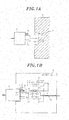
- the locking mechanism unit 23 of the plug 2 performs locking operation as shown in Fig.
- the locking mechanism unit 23 is released. That is, if the locking mechanism unit 23 is moved in the direction from the receptacle 3 to the plug 2 in the state in which the plug 2 is inserted in the receptacle 3, the movable piece 38 moves upward in Figs. 4A to 4C . Accordingly, the state in which the movable piece 38 pushes the one end portions of the opening/closing members 39 is released, and the contacts 39a of the opening/closing members 39 are separated from each other, so that no current flows through the power line 32.
- the contacts 39a of the opening/closing members 39 are always in the contact state, in the lock state of the locking mechanism unit 23, in which the plug 2 cannot be freely removed from the receptacle 3. Furthermore, in the release state of the locking mechanism unit 23, the contacts 39a of the opening/closing members 39 are always in the separation state, in which the plug 2 can be freely removed from the receptacle 3. For this reason, it is possible to prevent the plug 2 from being unintentionally removed from the receptacle 3 in the conducting state and to prevent an arc from being generated even when the plug 2 is removed from the receptacle 3, thereby improving safety.
- the receptacle 3 is provided with a measurement unit 35 for measuring a current value of current flowing therethrough, and a control unit 40 for displaying the conducting state of the receptacle 3 on an display unit 41 when the current value is detected from the measurement unit 35.
- the plug 2 is provided with a measurement unit 24 for measuring a current value of current flowing therethrough, and a control unit 25 for displaying the conducting state of the plug 2 on a display unit 26 when the current value is detected from the measurement unit 22.
- Fig. 5A the receptacle 3 is provided with a measurement unit 35 for measuring a current value of current flowing therethrough, and a control unit 40 for displaying the conducting state of the receptacle 3 on an display unit 41 when the current value is detected from the measurement unit 35.
- the plug 2 is provided with a measurement unit 24 for measuring a current value of current flowing therethrough, and a control unit 25 for displaying the conducting state of the plug 2 on a display unit 26 when the current value is detected from the measurement unit 22.
- the display unit 26 or 41 may be, for example, a light emitting diode (LED) or a liquid crystal display unit.
- the LED may emits red light in the conducting state and emits green light or turns off the light in the non-conducting state.
- the liquid crystal display unit may display a current value.
- control unit 40 or 25 and the display unit 41 or 26 may be provided in either one of the receptacle 3 or the plug 2.
- the conducting state may be displayed on at least one of the display unit 26 of the plug 2 and the display unit 41 of the receptacle 3. This makes users pay attention not to remove the plug 2 in the conducting state, thereby improving safety.
- the fifth embodiment may be used in combination with the first to fourth embodiments. Furthermore, in a case where the embodiment shown in Fig. 5A is combined with the second embodiment, the function of the control unit 40 shown in Fig. 5A may be added to the control unit 36 provided in the second embodiment.
Landscapes
- Engineering & Computer Science (AREA)
- Microelectronics & Electronic Packaging (AREA)
- Details Of Connecting Devices For Male And Female Coupling (AREA)
Applications Claiming Priority (2)
| Application Number | Priority Date | Filing Date | Title |
|---|---|---|---|
| JP2010212740 | 2010-09-22 | ||
| PCT/IB2011/002168 WO2012038797A1 (ja) | 2010-09-22 | 2011-09-20 | 直流コンセン卜及びプラグ |
Publications (2)
| Publication Number | Publication Date |
|---|---|
| EP2621028A1 true EP2621028A1 (de) | 2013-07-31 |
| EP2621028A4 EP2621028A4 (de) | 2014-05-21 |
Family
ID=45873501
Family Applications (1)
| Application Number | Title | Priority Date | Filing Date |
|---|---|---|---|
| EP11826468.8A Withdrawn EP2621028A4 (de) | 2010-09-22 | 2011-09-20 | Gefäss und stopfen dafür |
Country Status (5)
| Country | Link |
|---|---|
| US (1) | US20130194734A1 (de) |
| EP (1) | EP2621028A4 (de) |
| JP (1) | JP5988190B2 (de) |
| TW (1) | TW201225434A (de) |
| WO (1) | WO2012038797A1 (de) |
Cited By (5)
| Publication number | Priority date | Publication date | Assignee | Title |
|---|---|---|---|---|
| WO2017190833A1 (de) * | 2016-05-04 | 2017-11-09 | Rosenberger Hochfrequenztechnik Gmbh & Co. Kg | Hvil-system |
| EP3396788A1 (de) * | 2017-04-27 | 2018-10-31 | Vestel Elektronik Sanayi ve Ticaret A.S. | Sichere verriegelung von intelligenten steckeradaptern an steckdosen |
| KR20190006565A (ko) * | 2016-05-20 | 2019-01-18 | 아강글 테크놀로지 컴퍼니 리미티드 | 지능형 전원 연결 방법 및 지능형 커넥터 |
| WO2023285283A1 (de) * | 2021-07-12 | 2023-01-19 | Phoenix Contact Gmbh & Co. Kg | Zwischenstecker zur gleichspannungsabschaltung |
| BE1030845B1 (de) * | 2022-09-05 | 2024-04-02 | Phoenix Contact Gmbh & Co | Gleichspannungsschaltgerät mit integriertem Unterbrechungsmechanismus |
Families Citing this family (25)
| Publication number | Priority date | Publication date | Assignee | Title |
|---|---|---|---|---|
| CN202856062U (zh) * | 2012-11-05 | 2013-04-03 | 京东方科技集团股份有限公司 | Usb公端、usb母端及usb端口连接装置 |
| CN104346259A (zh) * | 2013-08-02 | 2015-02-11 | 昆山研达电脑科技有限公司 | 插头移除提醒方法及其系统 |
| US9525247B2 (en) * | 2015-03-11 | 2016-12-20 | Eaton Corporation | Interlocking outlet and associated method |
| US9899762B2 (en) | 2015-04-27 | 2018-02-20 | Steven Levine | Electrical receptacle |
| US9666977B2 (en) | 2015-07-29 | 2017-05-30 | Abb Schweiz Ag | Direct current socket with direct current arc protection |
| WO2017047463A1 (ja) * | 2015-09-14 | 2017-03-23 | 株式会社オートネットワーク技術研究所 | 通電システム及びオス型の端子 |
| JP6631169B2 (ja) * | 2015-09-14 | 2020-01-15 | 株式会社オートネットワーク技術研究所 | 通電システム |
| EP3353862A1 (de) | 2015-09-24 | 2018-08-01 | ABB Schweiz AG | Gleitkontaktanordnung zur beschleunigung der relativen trenngeschwindigkeit zwischen stecker- und buchsenkontakten |
| JP6720982B2 (ja) * | 2015-11-27 | 2020-07-08 | ソニー株式会社 | コネクタ、電動移動体及び電力供給システム |
| USD843318S1 (en) * | 2016-03-11 | 2019-03-19 | David Baum | Plug connector for device charging |
| US10291065B2 (en) * | 2016-04-04 | 2019-05-14 | Computime, Ltd. | Robust and high current smart-plug |
| CN106992371A (zh) * | 2017-05-28 | 2017-07-28 | 詹胜超 | 一种手机构件 |
| US10540528B1 (en) | 2017-12-11 | 2020-01-21 | Trexler Technologies, Inc. | Methods of making and using an identification tag system for use with an electromagnetic energy cable |
| US10720737B2 (en) * | 2017-12-11 | 2020-07-21 | Arthur T. Schmidt, III | Methods of making and using an identification tag system for use with an electrical breaker panel and an electrical outlet |
| US10401431B1 (en) * | 2018-11-30 | 2019-09-03 | Arthur T. Schmidt, III | Methods of making and using an identification tag system for use with an electrical breaker panel and an electrical outlet |
| US10325192B1 (en) * | 2017-12-11 | 2019-06-18 | Hayden T. Schmidt | Electrical outlet/electrical switch identification system for use with an electrical breaker panel and method of making and using the same |
| CN108988080A (zh) * | 2018-07-09 | 2018-12-11 | 深圳市吉影科技有限公司 | 一种应用于水下产品的通电装置 |
| JP7342365B2 (ja) * | 2019-01-22 | 2023-09-12 | 京セラドキュメントソリューションズ株式会社 | コネクター検査器具、コネクターセット |
| JP7373738B2 (ja) * | 2019-03-28 | 2023-11-06 | パナソニックIpマネジメント株式会社 | 配線器具システム及びユニット装置 |
| CN110098514B (zh) * | 2019-05-16 | 2020-07-17 | 宁波均胜新能源汽车技术有限公司 | 一种新能源汽车充电防脱落机构 |
| DE102020105421A1 (de) | 2020-02-29 | 2021-09-02 | Airbus Operations Gmbh | Anschlussanordnung zum elektrischen Anschluss eines Flachbandkabels in einem Flugzeug |
| US11431137B2 (en) * | 2021-01-08 | 2022-08-30 | II Stephen Saxon Fuller | Electrical outlet with safety feature |
| DE102021108607A1 (de) | 2021-04-07 | 2022-10-13 | WAGO Verwaltungsgesellschaft mit beschränkter Haftung | System zur lösbaren verbindung elektrischer leiter |
| JP7381520B2 (ja) * | 2021-06-11 | 2023-11-15 | 矢崎総業株式会社 | 不正接続検出装置 |
| CN117276985B (zh) * | 2023-09-12 | 2024-03-15 | 杭州汉莱电器有限公司 | 一种多孔自保护插座 |
Family Cites Families (14)
| Publication number | Priority date | Publication date | Assignee | Title |
|---|---|---|---|---|
| JPS6115231A (ja) * | 1984-06-30 | 1986-01-23 | Tokyo Juki Ind Co Ltd | 情報処理用電子機器 |
| JP3135040B2 (ja) * | 1995-11-30 | 2001-02-13 | 矢崎総業株式会社 | 電気自動車の充電用コネクタ |
| JP2000221218A (ja) * | 1999-02-01 | 2000-08-11 | Shoei Denshi Kogyo Kk | 電力検知ユニット、コネクター、スイッチ装置および電力使用状態管理システム |
| JP2002101508A (ja) * | 2000-09-26 | 2002-04-05 | Matsushita Electric Works Ltd | コンセント盤及び電源プラグ |
| JP2005235679A (ja) * | 2004-02-23 | 2005-09-02 | Fujitsu Support & Service Kk | 電源プラグ抜け防止コンセント |
| US7614893B2 (en) * | 2005-04-04 | 2009-11-10 | Ati Technologies Ulc | Connector locking latch with signal providing early warning of disconnection |
| JP2007042408A (ja) * | 2005-08-03 | 2007-02-15 | Kawamura Electric Inc | コンセント |
| US7611366B2 (en) * | 2005-11-21 | 2009-11-03 | The Southern Company | Meter socket bypass disconnect device |
| JP2007329046A (ja) * | 2006-06-08 | 2007-12-20 | Nippon Telegr & Teleph Corp <Ntt> | 直流コンセント |
| CN201057625Y (zh) * | 2006-11-17 | 2008-05-07 | 周建林 | 电性检知保护装置 |
| JP2009146778A (ja) * | 2007-12-14 | 2009-07-02 | Panasonic Electric Works Co Ltd | 直流接続装置 |
| JP2009146777A (ja) | 2007-12-14 | 2009-07-02 | Panasonic Electric Works Co Ltd | 直流接続装置 |
| JP2009146827A (ja) | 2007-12-17 | 2009-07-02 | Panasonic Electric Works Co Ltd | 直流コンセント |
| JP5261141B2 (ja) * | 2008-11-11 | 2013-08-14 | 富士通コンポーネント株式会社 | コネクタ及び電源供給ユニット |
-
2011
- 2011-09-13 JP JP2011199890A patent/JP5988190B2/ja active Active
- 2011-09-20 TW TW100133740A patent/TW201225434A/zh unknown
- 2011-09-20 EP EP11826468.8A patent/EP2621028A4/de not_active Withdrawn
- 2011-09-20 WO PCT/IB2011/002168 patent/WO2012038797A1/ja active Application Filing
-
2013
- 2013-03-14 US US13/804,605 patent/US20130194734A1/en not_active Abandoned
Non-Patent Citations (2)
| Title |
|---|
| No further relevant documents disclosed * |
| See also references of WO2012038797A1 * |
Cited By (9)
| Publication number | Priority date | Publication date | Assignee | Title |
|---|---|---|---|---|
| WO2017190833A1 (de) * | 2016-05-04 | 2017-11-09 | Rosenberger Hochfrequenztechnik Gmbh & Co. Kg | Hvil-system |
| US10797444B2 (en) | 2016-05-04 | 2020-10-06 | Rosenberger Hochfrequenztechnik Gmbh | High-voltage interlock system |
| KR20190006565A (ko) * | 2016-05-20 | 2019-01-18 | 아강글 테크놀로지 컴퍼니 리미티드 | 지능형 전원 연결 방법 및 지능형 커넥터 |
| EP3460925A4 (de) * | 2016-05-20 | 2019-06-19 | Argangle Technology Co. Ltd | Verfahren für intelligente stromverbindung und intelligenter verbinder |
| EP3396788A1 (de) * | 2017-04-27 | 2018-10-31 | Vestel Elektronik Sanayi ve Ticaret A.S. | Sichere verriegelung von intelligenten steckeradaptern an steckdosen |
| WO2023285283A1 (de) * | 2021-07-12 | 2023-01-19 | Phoenix Contact Gmbh & Co. Kg | Zwischenstecker zur gleichspannungsabschaltung |
| BE1029583B1 (de) * | 2021-07-12 | 2023-02-06 | Phoenix Contact Gmbh & Co | Zwischenstecker zur Gleichspannungsabschaltung |
| BE1030845B1 (de) * | 2022-09-05 | 2024-04-02 | Phoenix Contact Gmbh & Co | Gleichspannungsschaltgerät mit integriertem Unterbrechungsmechanismus |
| WO2024052213A3 (de) * | 2022-09-05 | 2024-05-30 | Phoenix Contact Gmbh & Co.Kg | Gleichspannungsschaltgerät mit integriertem unterbrechungsmechanismus |
Also Published As
| Publication number | Publication date |
|---|---|
| JP2012089477A (ja) | 2012-05-10 |
| US20130194734A1 (en) | 2013-08-01 |
| TW201225434A (en) | 2012-06-16 |
| WO2012038797A1 (ja) | 2012-03-29 |
| EP2621028A4 (de) | 2014-05-21 |
| JP5988190B2 (ja) | 2016-09-07 |
Similar Documents
| Publication | Publication Date | Title |
|---|---|---|
| EP2621028A1 (de) | Gefäss und stopfen dafür | |
| US9124097B2 (en) | Polarity correcting device | |
| US7924541B2 (en) | Power plug with leakage current protection function | |
| US9744866B2 (en) | Electric power control device | |
| US8737026B2 (en) | Electric vehicle charging cord set | |
| US9153980B2 (en) | Portable electric vehicle recharging device | |
| ES2743400T3 (es) | Anunciador remoto para sistema de alimentación de vehículo eléctrico | |
| US20190356091A1 (en) | Power connector using resistive sensing | |
| JP6123134B2 (ja) | 給電制御装置 | |
| JP5032969B2 (ja) | 直流コンセント | |
| JP2009142012A (ja) | 直流配電システム | |
| EP1525650A1 (de) | Schalteinheit zum schalten einer verbindung zwischen netz und last | |
| GB2477964A (en) | Making an electrical connection with an insulated electricity cable | |
| JP2012161155A (ja) | コンセント及び給電システム | |
| JP2011146328A (ja) | 配電装置 | |
| CN101820164A (zh) | 漏电检测模块以及具有漏电检测模块的漏电保护断路器 | |
| JP2009165251A (ja) | 直流配電システム | |
| JP4981657B2 (ja) | 分電盤 | |
| JP2015070758A (ja) | 表示機能付き分電盤 | |
| US11431137B2 (en) | Electrical outlet with safety feature | |
| US20220344878A1 (en) | Electrical Outlet with Safety Feature | |
| JP2014116075A (ja) | 分岐ブレーカ及び分電盤 | |
| CN213340993U (zh) | 漏电保护插头 | |
| US12126124B2 (en) | Power connector using resistive sensing | |
| JP5043642B2 (ja) | 回路遮断器 |
Legal Events
| Date | Code | Title | Description |
|---|---|---|---|
| PUAI | Public reference made under article 153(3) epc to a published international application that has entered the european phase |
Free format text: ORIGINAL CODE: 0009012 |
|
| 17P | Request for examination filed |
Effective date: 20130321 |
|
| AK | Designated contracting states |
Kind code of ref document: A1 Designated state(s): AL AT BE BG CH CY CZ DE DK EE ES FI FR GB GR HR HU IE IS IT LI LT LU LV MC MK MT NL NO PL PT RO RS SE SI SK SM TR |
|
| DAX | Request for extension of the european patent (deleted) | ||
| A4 | Supplementary search report drawn up and despatched |
Effective date: 20140425 |
|
| RIC1 | Information provided on ipc code assigned before grant |
Ipc: H01R 13/639 20060101ALI20140417BHEP Ipc: H01R 13/66 20060101ALN20140417BHEP Ipc: H01R 13/641 20060101AFI20140417BHEP Ipc: H01R 103/00 20060101ALN20140417BHEP Ipc: H01R 13/703 20060101ALI20140417BHEP |
|
| STAA | Information on the status of an ep patent application or granted ep patent |
Free format text: STATUS: THE APPLICATION IS DEEMED TO BE WITHDRAWN |
|
| 18D | Application deemed to be withdrawn |
Effective date: 20141125 |