EP2614271B1 - Dämpfventil für einen schwingungsdämpfer - Google Patents
Dämpfventil für einen schwingungsdämpfer Download PDFInfo
- Publication number
- EP2614271B1 EP2614271B1 EP11733685.9A EP11733685A EP2614271B1 EP 2614271 B1 EP2614271 B1 EP 2614271B1 EP 11733685 A EP11733685 A EP 11733685A EP 2614271 B1 EP2614271 B1 EP 2614271B1
- Authority
- EP
- European Patent Office
- Prior art keywords
- damping valve
- passage
- valve seat
- valve according
- damping
- Prior art date
- Legal status (The legal status is an assumption and is not a legal conclusion. Google has not performed a legal analysis and makes no representation as to the accuracy of the status listed.)
- Active
Links
Images


Classifications
-
- F—MECHANICAL ENGINEERING; LIGHTING; HEATING; WEAPONS; BLASTING
- F16—ENGINEERING ELEMENTS AND UNITS; GENERAL MEASURES FOR PRODUCING AND MAINTAINING EFFECTIVE FUNCTIONING OF MACHINES OR INSTALLATIONS; THERMAL INSULATION IN GENERAL
- F16F—SPRINGS; SHOCK-ABSORBERS; MEANS FOR DAMPING VIBRATION
- F16F9/00—Springs, vibration-dampers, shock-absorbers, or similarly-constructed movement-dampers using a fluid or the equivalent as damping medium
- F16F9/32—Details
- F16F9/34—Special valve constructions; Shape or construction of throttling passages
- F16F9/3405—Throttling passages in or on piston body, e.g. slots
Definitions
- the invention relates to a damping valve according to the preamble of patent claim 1.
- a damping valve comprises a throttle duct, the outlet side of which is at least largely covered by a valve disk.
- the valve body has obliquely to the longitudinal axis of a piston rod extending throttle channels.
- the inlet openings of the throttle channels lie on a larger pitch circle diameter than the outlet openings.
- the annular trench is eccentric to the valve body center, so that in a central arrangement of at least one valve trench covering the ring trench is a one-sided Abhubterrorism which continues with increasing flow in the circumferential direction.
- a damping valve according to the DE 21 09 398 C3 with at least two disadvantages On the one hand, it is technically complicated to produce inclined throttle channels. Furthermore, only the area radially within the pitch circle diameter of the inlet openings is available for the ring trench. Smaller valve discs must be made thinner with a similar opening behavior than larger valve discs. However, thinner valve discs are not so durable.
- the object of the present invention is to develop a generic type damping valve such that the known disadvantages are eliminated.
- the object is achieved by the passage channels extending parallel to a central axis and a valve seat surface forming web separates the group of passageways for the one flow direction of the group of passageways for the other flow direction, the distance to the central axis of the valve seat in the region of at least two outlet openings at least one group of the passage channels is executed differently.
- valve seat surface is designed meandering.
- an inlet and an outlet opening alternate in the circumferential direction. They are separated by the web of each other, wherein the web excludes the inlet openings for digging the outlet openings.
- the outlet openings of the passage channels are at substantially the same distance from the valve seat surface.
- the Umlenkweg to the outer edge of the valve disc is the same for all outlet openings.
- the Dämpfventil analyses an odd number of passage channels and the distances of the valve seat surface with respect to an axis of symmetry between a passageway and the central axis of the Dämpfventil stressess are designed mirror images. Starting from the outlet opening with the greatest distance between the valve seat surface and the central axis, the valve disk thereby lifts symmetrically. There is no pronounced deformation jump of the valve disc. The valve seat area area with the smallest distance and the valve seat area area with the greatest distance to the central axis are not executed directly next to each other in the circumferential direction.
- the passage channel for at least one flow direction on a rectangular basic shape and the outlet opening a plurality of funnel-shaped transitions.
- the goal of this measure is a turbulence-free as possible flow from the passageway into the trench.
- At least one funnel-shaped transition is aligned radially outward according to an advantageous subclaim.
- At least one funnel-shaped transition can extend in the circumferential direction of the trench.
- At least one passage for a flow direction is designed as a slot.
- the slot can be made curved in the circumferential direction in order to make optimum use of the surface area of the Dämpfventil stressess can.
- outlet opening radially outwardly has a greater width than radially inward.
- slot-shaped passageway which is widened in its areal extent in the region of the outlet opening in order to achieve the largest possible pressure-loaded surface on a valve disc.
- the outlet opening in the region of the inlet opening for the passage channel of the opposite flow direction has a substantially parallel sealing edge.
- the FIG. 1 shows a damping valve 1 for a vibration damper of any type.
- the damping valve 1 is embodied on a piston rod 3, of which only one piston rod pin 5 is dargterrorism.
- a Dämpfventilisation 7 of the damping valve 1 two separate groups of passage channels 9; 11, which extend substantially parallel to the central axis of the damping valve 1.
- the central axis of the damping valve 1 is congruent with the longitudinal axis of the piston rod 3 and the piston rod pin 5.
- the two groups of passage channels 9; 11 are flowed through by a damping medium in the operation of the damping valve opposite.
- the damping medium passes through inlet openings 13; 15 in the passageways 9; 11, the outlet openings 17; 19 of at least one valve disc 21; 23 are covered.
- Fig. 1 is exemplified a valve disc assembly shown. Many variations are conceivable.
- the complete damping valve 1 is fixed to the piston rod 3.
- the damper valve body has a central opening 27 for receiving the piston rod pin 5.
- Fig. 2 an annular clamping surface 31z for the at least one valve disc 21 is executed.
- the outer edge 33 of the clamping surface 31z defines a circumferential groove 35, which is closed by a closed meander-shaped valve seat surface 37, which is formed by a raised web 39, radially on the outside.
- a closed meander-shaped valve seat surface 37 which is formed by a raised web 39, radially on the outside.
- five passage channels 9a - 9c are arranged, exit the outlet openings 17 in the groove 35.
- the Passage channels 9a - 9d are all located on a common pitch circle diameter and have a rectangular basic shape.
- Each outlet opening 17 of this group of passage channels 9a-9c has a plurality of funnel-shaped transitions 41a-41c, which form the flow surface between the passage channels 9a-9c and the channel bottom. At least one of the funnel-shaped transitions 41 a of each outlet opening is directed radially outward. Although the radial distance of the radially outer funnel edge 41 a to the valve seat surface 37 is dimensionally equal at all outlet opening, the distance A 1 of the valve seat surface 37 to the central axis in the region of an outlet opening 9a is different from the distance A 2 of a valve seat surface or a valve seat surface region of a second Outlet opening 9b executed to the central axis. We have A 1 > A 2 > A 3 .
- the funnel angle of the transitions 41 varies slightly, since the passage channels 9a, 9b, 9c are arranged on a pitch circle.
- the passage channel 9 has at least one funnel-shaped transition 41b; 41 c in the circumferential direction of the trench.
- the damping valve body 7 has five passageways 9a; 9b; 9c and thus has an odd number of passage channels.
- the distances A 2 ; A 2 ; A 3 of the valve seat surface 37 with respect to an axis of symmetry 43 between the passage channel 9a and the central axis of the Dämpfventil stressess 7 are executed in mirror image.
- the passage channels 11 are arranged for the other flow direction. These passageways 11 are designed as a slot, as in the Fig. 2 it can be seen that the inlet opening 15 of the passage channels 11 shows.
- the outlet openings 19 of the passage channels radially outward have a greater width than radially inside and thus a cloverleaf-like shape.
- the outlet openings 19 are framed by raised valve seat surfaces 45, which are connected on a second cover side 47, in the further pressure side, to an annular clamping surface 31 d.
- the valve seat surfaces 45 have in the region of the inlet openings 13 for the passage channels 9 of the opposite flow direction to a substantially parallel sealing edge. Furthermore, radially extending portions of the valve seat surface 45 define an inflow funnel 49 for the passageways 9.
- valve disc 21 When pressure is applied to the at least one valve disk 21 via damping medium in the channel 35, the same pressure prevails within limits at each point, but the lever arm of the pressure force in the channel is at least one valve disk 21 at an outlet opening of the passage channel 9a and there Valve seat area is the longest. Consequently, the valve disc 21 at this point first lift off the valve seat surface 37 and damping medium can flow out of the channel 35. If the pressure continues to rise, then, starting from this valve seat surface area, mirror-symmetrically on both sides of the symmetry axis 43, a lift-off movement of the valve disk 21 takes place which is reduced in the circumferential direction a sufficiently large pressurization of the valve disc 21 lifts it completely from the valve seat surface 37.
Landscapes
- Engineering & Computer Science (AREA)
- General Engineering & Computer Science (AREA)
- Mechanical Engineering (AREA)
- Fluid-Damping Devices (AREA)
Description
- Die Erfindung betrifft ein Dämpfventil gemäß dem Oberbegriff von Patentanspruch 1.
- Bei einem konventionellen Schwingungsdämpfer wird Dämpfmedium infolge einer Federungsbewegung durch ein Dämpfventil verdrängt. In der Regel wird umfasst ein Dämpfventil einen Drosselkanal, dessen Austrittsseite zumindest größtenteils von einer Ventilscheibe abgedeckt wird. Wenn das Dämpfmedium in den Drosselkanal einströmt und die Ventilscheibe von der Austrittsöffnung abhebt, dann tritt zunehmend ein Geräuschproblem auf, da moderne Fahrzeuge über großflächige Karosserieteile verfügen und insgesamt ein geringeres Geräuschniveau im Fahrgastraum angestrebt wird. Ursächlich für das Geräuschproblem ist ein Kraftsprung in der Dämpfkraftentwicklung.
- Aus der
DE 21 09 398 C3 ist ein Dämpfventil für einen Schwingungsdämpfer bekannt, dessen Ventilkörper schräg zur Längsachse einer Kolbenstange verlaufende Drosselkanäle aufweist. Die Eintrittsöffnungen der Drosselkanäle liegen auf einem größeren Teilkreisdurchmesser als die Austrittsöffnungen. Dadurch ist es möglich, dass sämtliche Austrittsöffnungen auf einer Ventilkörperseite durch einen umlaufenden Ringgraben verbunden sind, der mittels einer äußeren ringförmigen Auflagefläche begrenzt wird. Der Ringgraben verläuft exzentrisch zur Ventilkörpermitte, so dass bei einer mittigen Anordnung mindestens einer den Ringgraben abdeckenden Ventilscheibe eine einseitige Abhubbewegung erfolgt, die sich bei zunehmender Anströmung in Umfangsrichtung fortsetzt. - Ein Dämpfventil gemäß der
DE 21 09 398 C3 mit zumindest zwei Nachteilen behaftet. Zum einen ist es technisch aufwändig schräg verlaufende Drosselkanäle herzustellen. Des Weiteren steht für den Ringgraben nur der Bereich radial innerhalb des Teilkreisdurchmessers der Eintrittsöffnungen zur Verfügung. Kleinere Ventilscheiben müssen bei vergleichbarem Öffnungsverhalten dünner ausgeführt werden als größere Ventilscheiben. Dünnere Ventilscheiben sind jedoch nicht so dauerfest. - Die Aufgabe der vorliegenden Erfindung besteht darin ein gattungsbildendes Dämpfventil derart weiterzuentwickeln, so dass die bekannten Nachteile behoben sind.
- Erfindungsgemäß wird die Aufgabe dadurch gelöst die Durchlasskanäle parallel zu einer Mittelachse verlaufen und ein die Ventilsitzfläche bildende Steg die Gruppe der Durchlasskanäle für die eine Durchströmungsrichtung von der Gruppe der Durchlasskanäle für die andere Durchströmungsrichtung trennt, wobei der Abstand zur Mittelachse der Ventilsitzfläche im Bereich mindestens zweier Austrittsöffnungen mindestens einer Gruppe der Durchlasskanäle unterschiedlich ausgeführt ist.
- Durch die unterschiedliche Ausführung der Abstände der Ventilsitzfläche wird eine gezielte Abhubbewegung der mindestens einen Ventilscheibe sichergestellt.
- Eine besonders günstige Flächenverteilung der Austritts- und Eintrittsöffnungen wird dadurch erreicht, dass die Ventilsitzfläche mäanderförmig ausgeführt ist. Praktisch wechselt sich in Umfangsrichtung eine Eintritts- mit einer Austrittsöffnung ab. Sie werden durch den Steg von einander getrennt, wobei der Steg die Eintrittsöffnungen zum Graben der Austrittsöffnungen ausgrenzt.
- Um eine möglichst direkt Druckkraft auf die Ventilscheibe ausüben zu können weisen die Austrittsöffnungen der Durchlasskanäle im Wesentlichen denselben Abstand zur Ventilsitzfläche auf. Der Umlenkweg zum äußeren Rand der Ventilscheibe ist dadurch bei allen Austrittsöffnungen gleich.
- In weiterer vorteilhafter Ausgestaltung weist der Dämpfventilkörper eine ungrade Anzahl von Durchlasskanälen auf und die Abstände der Ventilsitzfläche bezogen auf eine Symmetrieachse zwischen einem Durchlasskanal und der Mittelachse des Dämpfventilkörpers sind spiegelbildlich ausgeführt. Ausgehend von der Austrittsöffnung mit dem größten Abstand der Ventilsitzfläche zur Mittelachse hebt sich dadurch die Ventilscheibe symmetrisch an. Es gibt keinen ausgeprägten Verformungssprung der Ventilscheibe. Der Ventilsitzflächenbereich mit dem kleinsten Abstand und der Ventilsitzflächenbereich mit dem größten Abstand zur Mittelachse sind in Umfangsrichtung nicht direkt nebeneinander ausgeführt.
- In weiterer vorteilhafter Ausgestaltung weist der Durchlasskanal für mindestens eine Durchströmungsrichtung eine rechteckige Grundform und die Austrittsöffnung mehrere trichterförmige Übergänge auf. Das Ziel dieser Maßnahme ist eine möglichst turbolenzfreie Strömung aus dem Durchlasskanal in den Graben.
- Von den mehreren Übergängen ist gemäß einem vorteilhaften Unteranspruch mindestens ein trichterförmiger Übergang nach radial außen ausgerichtet.
- Des Weiteren kann mindestens ein trichterförmiger Übergang in Umfangsrichtung des Grabens verlaufen.
- Optional ist mindestens ein Durchtrittskanal für eine Durchströmungsrichtung als ein Langloch ausgeführt. Das Langloch kann in Umfangsrichtung gekrümmt ausgeführt sein, um den Oberflächenbereich des Dämpfventilkörpers optimal ausnutzen zu können.
- Es besteht die Möglichkeit, dass die Austrittsöffnung radial außen eine größere Breite aufweist als radial innen. Zwar liegt ein langlochförmiger Durchgangskanal vor, der jedoch im Bereich der Austrittsöffnung in seiner flächigen Erstreckung erweitert ist, um eine möglichst große druckbeaufschlagte Fläche an einer Ventilscheibe zu erreichen.
- Im Hinblick auf eine Maximierung der druckbeaufschlagten Fläche weist die Austrittsöffnung im Bereich der Eintrittsöffnung für den Durchtrittskanal der entgegen gesetzten Strömungsrichtung eine im Wesentlichen parallele Dichtkante auf.
- Anhand der folgenden Figurenbeschreibung soll die Erfindung näher erläutert werden.
- Es zeigt:
- Fig. 1
- Schnittdarstellung durch ein Dämpfventil
- Fig. 2
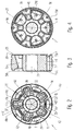
- Draufsicht auf einen Dämpfventilkörper mit einer Ventilsitzfläche für eine erste Durchströmungsrichtung
- Fig. 3
- Schnittdarstellung des Dämpfventilkörpers nach
Fig. 1 - Fig. 4
- Draufsicht des Dämpfventilkörpers mit einer Ventilsitzfläche für eine zweite Durchströmungsrichtung
- Fig. 5
- Perspektivische Darstellung des Kolbens gemäß
Fig. 2 - Fig. 6
- Perspektivische Darstellung des Kolbens gemäß
Fig. 4 - Die
Figur 1 zeigt ein Dämpfventil 1 für einen Schwingungsdämpfer beliebiger Bauart. Das Dämpfventil 1 ist an einer Kolbenstange 3 ausgeführt, von der lediglich ein Kolbenstangenzapfen 5 dargstellt ist. In der Zusammenschau mit denFig. 2 bis 6 ist erkennbar, dass ein Dämpfventilkörper 7 des Dämpfventils 1 zwei getrennte Gruppen von Durchlasskanälen 9; 11 aufweist, die sich im Wesentlichen parallel zur Mittelachse des Dämpfventils 1 erstrecken. Die Mittelachse des Dämpfventils 1 ist deckungsgleich mit der Längsachse der Kolbenstange 3 bzw. dem Kolbenstangenzapfen 5. Die beiden Gruppen von Durchlasskanälen 9; 11 werden im Betrieb des Dämpfventils von einem Dämpfmedium entgegengesetzt durchströmt. Dabei gelangt das Dämpfmedium über Eintrittsöffnungsöffnungen 13; 15 in die Durchlasskanäle 9; 11, deren Austrittsöffnungen 17; 19 von mindestens einer Ventilscheibe 21; 23 abgedeckt werden. In derFig. 1 ist beispielhaft eine Ventilscheibenanordnung dargestellt. Zahlreiche Variationen sind denkbar. Mittels einer Mutter 25 ist das komplette Dämpfventil 1 an der Kolbenstange 3 fixiert. - Wie aus der Zusammenschau der
Fig. 1 bis 6 erkennbar ist, verfügt der Dämpfventilkörper über eine zentrale Öffnung 27 zur Aufnahme des Kolbenstangenzapfens 5. Auf einer ersten Deckseite des Dämpfventilkörpers 7, im Weiteren Zugseite 29 genannt,Fig. 2 , ist eine kreisringförmige Spannfläche 31z für die mindestens eine Ventilscheibe 21 ausgeführt. Der äußere Rand 33 der Spannfläche 31z begrenzt eine umlaufende Rinne 35, die von einer geschlossenen mäanderförmigen Ventilsitzfläche 37, die von einem erhabenen Steg 39 gebildet wird, radial außen abgeschlossen ist. Innerhalb der Rinne 35 sind fünf Durchlasskanäle 9a - 9c angeordnet, deren Austrittsöffnungen 17 in der Rinne 35 auslaufen. Die Durchlasskanäle 9a - 9d befinden sich alle auf einem gemeinsamen Teilkreisdurchmesser und verfügen über einen rechteckige Grundform. Jede Austrittsöffnung 17 dieser Gruppe von Durchlasskanälen 9a - 9 c verfügt über mehrere trichterförmige Übergänge 41a - 41 c, die die Strömungsoberfläche zwischen den Durchlasskanälen 9a - 9c und dem Rinnengrund bilden. Mindestens einer der trichterförmigen Übergänge 41 a jeder Austrittsöffnung ist nach radial außen gerichtet. Der radiale Abstand des radial äußeren Trichterrands 41 a zur Ventilsitzfläche 37 ist zwar bei allen Austrittsöffnung maßlich gleich ausgeführt, jedoch ist der Abstand A1 der Ventilsitzfläche 37 zur Mittelachse im Bereich einer Austrittsöffnung 9a unterschiedlich zum Abstand A2 einer Ventilsitzfläche bzw. eines Ventilsitzflächenbereich einer zweiten Austrittsöffnung 9b zur Mittelachse ausgeführt. Es gilt A1 > A2 > A3. Der Trichterwinkel der Übergänge 41 variiert geringfügig, da die Durchlasskanäle 9a, 9b, 9c auf einem Teilkreis angeordnet sind. Zusätzlich verfügt der Durchlasskanal 9 über mindestens einen trichterförmigen Übergang 41b; 41 c in Umfangsrichtung des Grabens. - Es wurde bereits erwähnt, dass der Dämpfventilkörper 7 fünf Durchlasskanäle 9a; 9b; 9c und damit eine ungerade Anzahl von Durchlasskanälen aufweist. Die Abstände A2; A2; A3 der Ventilsitzfläche 37 bezogen auf eine Symmetrieachse 43 zwischen dem Durchlasskanal 9a und der Mittelachse des Dämpfventilkörpers 7 sind spiegelbildlich ausgeführt.
- In den Umfangsbereichen mit der geringsten Rinnenbreite sind die Durchlasskanäle 11 für die andere Durchströmungsrichtung angeordnet. Diese Durchlasskanäle 11 sind als Langloch ausgeführt, wie in der
Fig. 2 ersichtlich ist, die die Eintrittsöffnung 15 dieser Durchlasskanäle 11 zeigt. In denFig. 4 und6 wird deutlich, dass die Austrittsöffnungen 19 der Durchlasskanäle radial außen eine größere Breite als radial innen und damit eine kleeblattähnliche Form aufweisen. Die Austrittsöffnungen 19 werden von erhabenen Ventilsitzflächen 45 eingerahmt, die auf einer zweiten Deckseite 47, im Weiteren Druckseite, an eine kreisringförmige Spannfläche 31 d angeschlossen sind. Die Ventilsitzflächen 45 weisen im Bereich der Eintrittsöffnungen 13 für die Durchtrittskanäle 9 der entgegen gesetzten Strömungsrichtung eine dazu im Wesentlichen parallele Dichtkante auf. Des Weiteren begrenzen radial verlaufende Abschnitte der Ventilsitzfläche 45 einen Zuflusstrichter 49 für die Durchlasskanäle 9. - Zur Abstützung der Ventilscheiben 21; 23 auf der Druckseite 47 wie auch auf der Zugseite 29 können Unterstützungsflächen 51 d; 51z angeordnet sein, die in der Höhenniveaulage der Ventilsitzflächen 37; 45 ausgeführt sind.
- Bei einer Druckbeaufschlagung der mindestens einen Ventilscheibe 21 über Dämpfmedium in der Rinne 35 herrscht dort zwar in Grenzen an jeder Stelle derselbe Druck, jedoch ist der Hebelarm der Druckkraft in der Rinne auf die mindestens eine Ventilscheibe 21 an einer Austrittsöffnung des Durchlasskanals 9a und dem dort verlaufenden Ventilsitzbereich am längsten. Folglich wird die Ventilscheibe 21 an dieser Stelle zuerst von der Ventilsitzfläche 37 abheben und Dämpfmedium kann aus der Rinne 35 abfließen. Steigt der Druck weiter an, dann erfolgt ausgehend zu diesem Ventilsitzflächenbereich beidseitig spiegelbildlich zur Symmetrieachse 43 eine in Umfangsrichtung vermindert verlaufenden Abhubbewegung der Ventilscheibe 21. Bei einer ausreichend großen Druckbeaufschlagung der Ventilscheibe 21 hebt diese vollständig von der Ventilsitzfläche 37 ab.
-
- 1
- Dämpfventil
- 3
- Kolbenstange
- 5
- Kolbenstangenzapfen
- 7
- Dämpfventilkörper
- 9; 11
- Durchlasskanäle
- 13; 15
- Eintrittsöffnungen
- 17; 19
- Austrittsöffnungen
- 21; 23
- Ventilscheibe
- 25
- Mutter
- 27
- zentrale Öffnung
- 29
- Zugseite
- 31 d
- Spannfläche, druckseitig
- 31 z
- Spannfläche, zugseitig
- 33
- äußerer Rand der Spannfläche 31z
- 35
- Rinne
- 37
- Ventilsitzfläche
- 39
- Steg
- 41a, 41b, 41c
- trichterförmige Übergänge
- 43
- Symmetrieachse
- 45
- Ventilsitzfläche (druckseitig)
- 47
- Druckseite
- 49
- Zuflusstrichter
- 51d, 51z
- Unterstützungsflächen
Claims (10)
- Dämpfventil (1) für einen Schwingungsdämpfer, umfassend einen Dämpfventilkörper (7) mit getrennten Durchlasskanälen (9; 11) für unterschiedliche Durchströmungsrichtungen, wobei Austrittsöffnungen (17) mindestens zweier Durchlasskanäle (9a; 9b) über eine Rinne (35) miteinander verbunden sind und mindestens eine die Rinne (35) abdeckende auf einer Ventilsitzfläche (37) aufliegende Ventilscheibe (21) an einer definierten Stelle zuerst und dann von dort ausgehend nachfolgend am weiteren Umfang abhebt,
dadurch gekennzeichnet,
dass die Durchlasskanäle (9; 11) parallel zu einer Mittelachse des Dämpfventilkörpers (7) verlaufen und ein die Ventilsitzfläche (37) bildender Steg (39) die Gruppe der Durchlasskanäle (9) für die eine Durchströmungsrichtung von der Gruppe der Durchlasskanäle (11) für die andere Durchströmungsrichtung trennt, wobei die Abstände (A1; A2; A3) der Ventilsitzfläche (37) zur Mittelachse im Bereich mindestens zweier Austrittsöffnungen (9a; 9b; 9c) mindestens einer Gruppe der Durchlasskanäle unterschiedlich ausgeführt sind. - Dämpfventil nach Anspruch 1
dadurch gekennzeichnet,
dass die Ventilsitzfläche (37) mäanderförmig ausgeführt ist. - Dämpfventil nach Anspruch 1,
dadurch gekennzeichnet,
dass die Austrittsöffnungen (17) der Durchlasskanäle (9) im Wesentlichen denselben radialen Abstand zur Ventilsitzfläche (37) aufweisen. - Dämpfventil nach Anspruch 1,
dadurch gekennzeichnet,
dass der Dämpfventilkörper (7) eine ungrade Anzahl von Durchlasskanälen (9) aufweist und die Abstände (A2; A3) der Ventilsitzfläche (37) bezogen auf eine Symmetrieachse (43) zwischen einem Durchlasskanal (9a) und der Mittelachse des Dämpfventilkörpers (7) spiegelbildlich ausgeführt sind. - Dämpfventil nach Anspruch 1,
dadurch gekennzeichnet,
dass der Durchlasskanal (9) für mindestens eine Durchströmungsrichtung eine rechteckige Grundform aufweist und die Austrittsöffnung (17) mehrere trichterförmige Übergänge (41a; 41b; 41 c) aufweist. - Dämpfventil nach Anspruch 5,
dadurch gekennzeichnet,
dass mindestens ein trichterförmiger Übergang (41) nach radial außen ausgerichtet ist. - Dämpfventil nach Anspruch 5,
dadurch gekennzeichnet,
dass mindestens ein trichterförmiger Übergang (41b; 41 c) in Umfangsrichtung der Rinne (35) verläuft. - Dämpfventil nach Anspruch 1,
dadurch gekennzeichnet,
dass der mindestens eine Durchtrittskanal (11) für eine Durchströmungsrichtung als ein Langloch ausgeführt ist. - Dämpfventil nach Anspruch 8,
dadurch gekennzeichnet,
dass die Austrittsöffnung (19) radial außen eine größere Breite aufweist als radial innen. - Dämpfventil nach Anspruch 8,
dadurch gekennzeichnet,
dass die Austrittsöffnung (19) im Bereich der Eintrittsöffnung (13) für den Durchtrittskanal (9) der entgegen gesetzten Strömungsrichtung eine im Wesentlichen parallele Dichtkante aufweist.
Applications Claiming Priority (2)
| Application Number | Priority Date | Filing Date | Title |
|---|---|---|---|
| DE102010040458A DE102010040458A1 (de) | 2010-09-09 | 2010-09-09 | Dämpfventil für einen Schwingungsdämpfer |
| PCT/EP2011/062137 WO2012031805A1 (de) | 2010-09-09 | 2011-07-15 | Dämpfventil für einen schwingungsdämpfer |
Publications (2)
| Publication Number | Publication Date |
|---|---|
| EP2614271A1 EP2614271A1 (de) | 2013-07-17 |
| EP2614271B1 true EP2614271B1 (de) | 2016-06-29 |
Family
ID=44582908
Family Applications (1)
| Application Number | Title | Priority Date | Filing Date |
|---|---|---|---|
| EP11733685.9A Active EP2614271B1 (de) | 2010-09-09 | 2011-07-15 | Dämpfventil für einen schwingungsdämpfer |
Country Status (3)
| Country | Link |
|---|---|
| EP (1) | EP2614271B1 (de) |
| DE (1) | DE102010040458A1 (de) |
| WO (1) | WO2012031805A1 (de) |
Families Citing this family (16)
| Publication number | Priority date | Publication date | Assignee | Title |
|---|---|---|---|---|
| SE533996C2 (sv) * | 2009-04-23 | 2011-03-22 | Oehlins Racing Ab | Tryckregulator i en stötdämparventil |
| DE102014201481B4 (de) | 2014-01-28 | 2022-03-10 | Zf Friedrichshafen Ag | Schwingungsdämpfer, sowie Kolbenventil für einen Schwingungsdämpfer |
| DE102014203842A1 (de) * | 2014-03-03 | 2015-09-03 | Zf Friedrichshafen Ag | Ventil, insbesondere für einen Schwingungsdämpfer |
| EP3147535B1 (de) * | 2014-05-20 | 2019-11-06 | Showa Corporation | Druckdämpfungsvorrichtung |
| DE102014223085B4 (de) * | 2014-11-12 | 2021-11-11 | Zf Friedrichshafen Ag | Dämpfventil für einen Schwingungsdämpfer |
| DE102014223086A1 (de) * | 2014-11-12 | 2016-05-12 | Zf Friedrichshafen Ag | Dämpfventil für einen Schwingungsdämpfer |
| DE102014223084A1 (de) | 2014-11-12 | 2016-05-12 | Zf Friedrichshafen Ag | Dämpfventil für einen Schwingungsdämpfer |
| DE102015217764A1 (de) * | 2015-09-17 | 2017-03-23 | Zf Friedrichshafen Ag | Dämpfventil für einen Schwingungsdämpfer |
| DE102015221763A1 (de) * | 2015-11-05 | 2017-05-11 | Zf Friedrichshafen Ag | Dämpfventil |
| JP6594226B2 (ja) | 2016-02-25 | 2019-10-23 | 株式会社ショーワ | 圧力緩衝装置および流路形成部材 |
| DE102018214148B4 (de) * | 2018-08-22 | 2022-09-01 | Zf Friedrichshafen Ag | Dämpfventil für einen Schwingungsdämpfer |
| DE102018218460A1 (de) | 2018-10-29 | 2020-04-30 | Zf Friedrichshafen Ag | Dämpfventil für einen Schwingungsdämpfer |
| DE102019209758B3 (de) * | 2019-07-03 | 2020-11-26 | Zf Friedrichshafen Ag | Dämpfventil für einen Schwingungsdämpfer |
| DE102019209761A1 (de) * | 2019-07-03 | 2021-01-07 | Zf Friedrichshafen Ag | Dämpfventil für einen Schwingungsdämpfer |
| DE102020209807A1 (de) | 2020-08-04 | 2022-02-10 | Zf Friedrichshafen Ag | Dämpfventil für einen Schwingungsdämpfer |
| DE102020209805A1 (de) | 2020-08-04 | 2022-02-10 | Zf Friedrichshafen Ag | Dämpfventil für einen Schwingungsdämpfer |
Family Cites Families (13)
| Publication number | Priority date | Publication date | Assignee | Title |
|---|---|---|---|---|
| DE7000825U (de) * | 1970-01-13 | 1970-09-17 | Bilstein August Fa | Kolben fuer hydraulische schwingungsdaempfer. |
| DE2109398C3 (de) | 1971-02-27 | 1979-11-15 | Fichtel & Sachs Ag, 8720 Schweinfurt | Stoßdämpferventil mit kontinuierlichem Übergang |
| JPH0438112Y2 (de) | 1985-06-29 | 1992-09-07 | ||
| JPS6318643U (de) | 1986-07-22 | 1988-02-06 | ||
| JP3123021B2 (ja) | 1989-11-20 | 2001-01-09 | カヤバ工業株式会社 | 油圧緩衝器のバルブ装置 |
| JP2958333B2 (ja) | 1989-11-24 | 1999-10-06 | カヤバ工業株式会社 | 油圧緩衝器のバルブ装置 |
| DE4033186A1 (de) * | 1990-10-19 | 1992-04-23 | Stabilus Gmbh | Drosseleinrichtung mit bewegungsrichtungsabhaengiger bypass-schaltung |
| DE9103740U1 (de) * | 1991-03-27 | 1991-06-20 | Ringsdorff-Werke GmbH, 5300 Bonn | Stoßdämpferkolben aus ungleichen, gefügten Teilen |
| DE4410996C1 (de) * | 1994-03-30 | 1995-06-01 | Fichtel & Sachs Ag | Schwingungsdämpfer |
| JP4564675B2 (ja) * | 2000-11-30 | 2010-10-20 | カヤバ工業株式会社 | 油圧緩衝器のバルブ構造 |
| DE102006028745A1 (de) * | 2005-06-21 | 2007-05-03 | Tenneco Automotive Operating Company Inc., Lake Forest | Vierteiliger Kolben |
| US20070034466A1 (en) * | 2005-08-15 | 2007-02-15 | Tenneco Automotive Operating Company, Inc. | Asymmetrical intake damper valve |
| US7743896B2 (en) * | 2006-10-11 | 2010-06-29 | Tenneco Automotive Operating Company Inc. | Shock absorber having a continuously variable semi-active valve |
-
2010
- 2010-09-09 DE DE102010040458A patent/DE102010040458A1/de not_active Withdrawn
-
2011
- 2011-07-15 EP EP11733685.9A patent/EP2614271B1/de active Active
- 2011-07-15 WO PCT/EP2011/062137 patent/WO2012031805A1/de not_active Ceased
Also Published As
| Publication number | Publication date |
|---|---|
| DE102010040458A1 (de) | 2012-03-15 |
| EP2614271A1 (de) | 2013-07-17 |
| WO2012031805A1 (de) | 2012-03-15 |
Similar Documents
| Publication | Publication Date | Title |
|---|---|---|
| EP2614271A1 (de) | Dämpfventil für einen schwingungsdämpfer | |
| DE10351357B3 (de) | Dämpfventil mit richtungsabhängig schaltbaren Querschnitt | |
| DE112014004961T5 (de) | Stossdämpfer | |
| WO2016066599A1 (de) | Kühlkanalabdeckung sowie mit einer kühlkanalabdeckung versehener kolben | |
| DE102014102617A1 (de) | Hydraulikventil für einen Schwenkmotorversteller einer Nockenwelle | |
| DE102014205855A1 (de) | Dämpfventilanordnung mit einer mehrstufigen Dämpfkraftkennlinie | |
| DE102010062324A1 (de) | Dämpfventilanordnung für einen Schwingungsdämpfer | |
| WO2018202386A1 (de) | Dämpfventil für einen schwingungsdämpfer | |
| EP3218618B1 (de) | Dämpfventil für einen schwingungsdämpfer | |
| EP0632212A2 (de) | Kolben für einen hydraulischen Schwingungsdämpfer | |
| DE102007018160A1 (de) | Lagerteller für eine Schraubenfeder eines Federbeines | |
| DE102010054302A1 (de) | Fliehkraftpendel | |
| DE102016213328A1 (de) | Dämpfventil mit richtungsabhängigem Voröffnungsquerschnitt für einen Schwingungsdämpfer | |
| DE102008035750A1 (de) | Bremsscheibe für Scheibenbremsen | |
| DE10124582C1 (de) | Dämpfventil | |
| DE2712034A1 (de) | Ventilanordnung fuer teleskopstossdaempfer | |
| DE102018220654A1 (de) | Dämpfventilanordnung, insbesondere für einen Schwingungsdämpfer | |
| DE10011168C1 (de) | Dämpfventil | |
| DE10309967B4 (de) | Kolben für einen hydraulischen Schwingungsdämpfer | |
| WO2017198405A1 (de) | Dämpfventil, insbesondere für einen schwingungsdämpfer | |
| DE102012221539A1 (de) | Ventileinrichtung zur Verwendung in einem Kraftstoffeinspritzsystem | |
| EP1809404B1 (de) | Filterplatte für einen partikelfilter | |
| DE102010041606B4 (de) | Dämpfventilanordnung für einen Schwingungsdämpfer | |
| DE19918350A1 (de) | Hydrolager | |
| DE102023208738A1 (de) | Rückschlagventil |
Legal Events
| Date | Code | Title | Description |
|---|---|---|---|
| PUAI | Public reference made under article 153(3) epc to a published international application that has entered the european phase |
Free format text: ORIGINAL CODE: 0009012 |
|
| 17P | Request for examination filed |
Effective date: 20130212 |
|
| AK | Designated contracting states |
Kind code of ref document: A1 Designated state(s): AL AT BE BG CH CY CZ DE DK EE ES FI FR GB GR HR HU IE IS IT LI LT LU LV MC MK MT NL NO PL PT RO RS SE SI SK SM TR |
|
| DAX | Request for extension of the european patent (deleted) | ||
| TPAC | Observations filed by third parties |
Free format text: ORIGINAL CODE: EPIDOSNTIPA |
|
| GRAP | Despatch of communication of intention to grant a patent |
Free format text: ORIGINAL CODE: EPIDOSNIGR1 |
|
| INTG | Intention to grant announced |
Effective date: 20160215 |
|
| GRAS | Grant fee paid |
Free format text: ORIGINAL CODE: EPIDOSNIGR3 |
|
| GRAA | (expected) grant |
Free format text: ORIGINAL CODE: 0009210 |
|
| AK | Designated contracting states |
Kind code of ref document: B1 Designated state(s): AL AT BE BG CH CY CZ DE DK EE ES FI FR GB GR HR HU IE IS IT LI LT LU LV MC MK MT NL NO PL PT RO RS SE SI SK SM TR |
|
| REG | Reference to a national code |
Ref country code: GB Ref legal event code: FG4D Free format text: NOT ENGLISH |
|
| REG | Reference to a national code |
Ref country code: CH Ref legal event code: EP |
|
| REG | Reference to a national code |
Ref country code: AT Ref legal event code: REF Ref document number: 809359 Country of ref document: AT Kind code of ref document: T Effective date: 20160715 |
|
| REG | Reference to a national code |
Ref country code: IE Ref legal event code: FG4D Free format text: LANGUAGE OF EP DOCUMENT: GERMAN |
|
| REG | Reference to a national code |
Ref country code: DE Ref legal event code: R096 Ref document number: 502011010053 Country of ref document: DE |
|
| REG | Reference to a national code |
Ref country code: LT Ref legal event code: MG4D |
|
| PG25 | Lapsed in a contracting state [announced via postgrant information from national office to epo] |
Ref country code: FI Free format text: LAPSE BECAUSE OF FAILURE TO SUBMIT A TRANSLATION OF THE DESCRIPTION OR TO PAY THE FEE WITHIN THE PRESCRIBED TIME-LIMIT Effective date: 20160629 Ref country code: LT Free format text: LAPSE BECAUSE OF FAILURE TO SUBMIT A TRANSLATION OF THE DESCRIPTION OR TO PAY THE FEE WITHIN THE PRESCRIBED TIME-LIMIT Effective date: 20160629 Ref country code: NO Free format text: LAPSE BECAUSE OF FAILURE TO SUBMIT A TRANSLATION OF THE DESCRIPTION OR TO PAY THE FEE WITHIN THE PRESCRIBED TIME-LIMIT Effective date: 20160929 |
|
| REG | Reference to a national code |
Ref country code: NL Ref legal event code: MP Effective date: 20160629 |
|
| PG25 | Lapsed in a contracting state [announced via postgrant information from national office to epo] |
Ref country code: GR Free format text: LAPSE BECAUSE OF FAILURE TO SUBMIT A TRANSLATION OF THE DESCRIPTION OR TO PAY THE FEE WITHIN THE PRESCRIBED TIME-LIMIT Effective date: 20160930 Ref country code: SE Free format text: LAPSE BECAUSE OF FAILURE TO SUBMIT A TRANSLATION OF THE DESCRIPTION OR TO PAY THE FEE WITHIN THE PRESCRIBED TIME-LIMIT Effective date: 20160629 Ref country code: HR Free format text: LAPSE BECAUSE OF FAILURE TO SUBMIT A TRANSLATION OF THE DESCRIPTION OR TO PAY THE FEE WITHIN THE PRESCRIBED TIME-LIMIT Effective date: 20160629 Ref country code: LV Free format text: LAPSE BECAUSE OF FAILURE TO SUBMIT A TRANSLATION OF THE DESCRIPTION OR TO PAY THE FEE WITHIN THE PRESCRIBED TIME-LIMIT Effective date: 20160629 Ref country code: RS Free format text: LAPSE BECAUSE OF FAILURE TO SUBMIT A TRANSLATION OF THE DESCRIPTION OR TO PAY THE FEE WITHIN THE PRESCRIBED TIME-LIMIT Effective date: 20160629 Ref country code: NL Free format text: LAPSE BECAUSE OF FAILURE TO SUBMIT A TRANSLATION OF THE DESCRIPTION OR TO PAY THE FEE WITHIN THE PRESCRIBED TIME-LIMIT Effective date: 20160629 |
|
| PG25 | Lapsed in a contracting state [announced via postgrant information from national office to epo] |
Ref country code: BE Free format text: LAPSE BECAUSE OF NON-PAYMENT OF DUE FEES Effective date: 20160731 |
|
| PG25 | Lapsed in a contracting state [announced via postgrant information from national office to epo] |
Ref country code: IS Free format text: LAPSE BECAUSE OF FAILURE TO SUBMIT A TRANSLATION OF THE DESCRIPTION OR TO PAY THE FEE WITHIN THE PRESCRIBED TIME-LIMIT Effective date: 20161029 Ref country code: RO Free format text: LAPSE BECAUSE OF FAILURE TO SUBMIT A TRANSLATION OF THE DESCRIPTION OR TO PAY THE FEE WITHIN THE PRESCRIBED TIME-LIMIT Effective date: 20160629 Ref country code: CZ Free format text: LAPSE BECAUSE OF FAILURE TO SUBMIT A TRANSLATION OF THE DESCRIPTION OR TO PAY THE FEE WITHIN THE PRESCRIBED TIME-LIMIT Effective date: 20160629 Ref country code: IT Free format text: LAPSE BECAUSE OF FAILURE TO SUBMIT A TRANSLATION OF THE DESCRIPTION OR TO PAY THE FEE WITHIN THE PRESCRIBED TIME-LIMIT Effective date: 20160629 Ref country code: SK Free format text: LAPSE BECAUSE OF FAILURE TO SUBMIT A TRANSLATION OF THE DESCRIPTION OR TO PAY THE FEE WITHIN THE PRESCRIBED TIME-LIMIT Effective date: 20160629 Ref country code: EE Free format text: LAPSE BECAUSE OF FAILURE TO SUBMIT A TRANSLATION OF THE DESCRIPTION OR TO PAY THE FEE WITHIN THE PRESCRIBED TIME-LIMIT Effective date: 20160629 |
|
| PG25 | Lapsed in a contracting state [announced via postgrant information from national office to epo] |
Ref country code: PT Free format text: LAPSE BECAUSE OF FAILURE TO SUBMIT A TRANSLATION OF THE DESCRIPTION OR TO PAY THE FEE WITHIN THE PRESCRIBED TIME-LIMIT Effective date: 20161031 Ref country code: SM Free format text: LAPSE BECAUSE OF FAILURE TO SUBMIT A TRANSLATION OF THE DESCRIPTION OR TO PAY THE FEE WITHIN THE PRESCRIBED TIME-LIMIT Effective date: 20160629 Ref country code: ES Free format text: LAPSE BECAUSE OF FAILURE TO SUBMIT A TRANSLATION OF THE DESCRIPTION OR TO PAY THE FEE WITHIN THE PRESCRIBED TIME-LIMIT Effective date: 20160629 Ref country code: PL Free format text: LAPSE BECAUSE OF FAILURE TO SUBMIT A TRANSLATION OF THE DESCRIPTION OR TO PAY THE FEE WITHIN THE PRESCRIBED TIME-LIMIT Effective date: 20160629 |
|
| REG | Reference to a national code |
Ref country code: CH Ref legal event code: PL |
|
| REG | Reference to a national code |
Ref country code: DE Ref legal event code: R097 Ref document number: 502011010053 Country of ref document: DE |
|
| PG25 | Lapsed in a contracting state [announced via postgrant information from national office to epo] |
Ref country code: CH Free format text: LAPSE BECAUSE OF NON-PAYMENT OF DUE FEES Effective date: 20160731 Ref country code: LI Free format text: LAPSE BECAUSE OF NON-PAYMENT OF DUE FEES Effective date: 20160731 |
|
| REG | Reference to a national code |
Ref country code: IE Ref legal event code: MM4A |
|
| PLBE | No opposition filed within time limit |
Free format text: ORIGINAL CODE: 0009261 |
|
| STAA | Information on the status of an ep patent application or granted ep patent |
Free format text: STATUS: NO OPPOSITION FILED WITHIN TIME LIMIT |
|
| GBPC | Gb: european patent ceased through non-payment of renewal fee |
Effective date: 20160929 |
|
| PG25 | Lapsed in a contracting state [announced via postgrant information from national office to epo] |
Ref country code: DK Free format text: LAPSE BECAUSE OF FAILURE TO SUBMIT A TRANSLATION OF THE DESCRIPTION OR TO PAY THE FEE WITHIN THE PRESCRIBED TIME-LIMIT Effective date: 20160629 |
|
| REG | Reference to a national code |
Ref country code: FR Ref legal event code: ST Effective date: 20170503 |
|
| 26N | No opposition filed |
Effective date: 20170330 |
|
| PG25 | Lapsed in a contracting state [announced via postgrant information from national office to epo] |
Ref country code: IE Free format text: LAPSE BECAUSE OF NON-PAYMENT OF DUE FEES Effective date: 20160715 Ref country code: GB Free format text: LAPSE BECAUSE OF NON-PAYMENT OF DUE FEES Effective date: 20160929 Ref country code: FR Free format text: LAPSE BECAUSE OF NON-PAYMENT OF DUE FEES Effective date: 20160829 |
|
| PG25 | Lapsed in a contracting state [announced via postgrant information from national office to epo] |
Ref country code: LU Free format text: LAPSE BECAUSE OF NON-PAYMENT OF DUE FEES Effective date: 20160715 Ref country code: BG Free format text: LAPSE BECAUSE OF FAILURE TO SUBMIT A TRANSLATION OF THE DESCRIPTION OR TO PAY THE FEE WITHIN THE PRESCRIBED TIME-LIMIT Effective date: 20160929 Ref country code: SI Free format text: LAPSE BECAUSE OF FAILURE TO SUBMIT A TRANSLATION OF THE DESCRIPTION OR TO PAY THE FEE WITHIN THE PRESCRIBED TIME-LIMIT Effective date: 20160629 |
|
| REG | Reference to a national code |
Ref country code: AT Ref legal event code: MM01 Ref document number: 809359 Country of ref document: AT Kind code of ref document: T Effective date: 20160715 |
|
| PG25 | Lapsed in a contracting state [announced via postgrant information from national office to epo] |
Ref country code: AT Free format text: LAPSE BECAUSE OF NON-PAYMENT OF DUE FEES Effective date: 20160715 |
|
| PG25 | Lapsed in a contracting state [announced via postgrant information from national office to epo] |
Ref country code: CY Free format text: LAPSE BECAUSE OF FAILURE TO SUBMIT A TRANSLATION OF THE DESCRIPTION OR TO PAY THE FEE WITHIN THE PRESCRIBED TIME-LIMIT Effective date: 20160629 Ref country code: HU Free format text: LAPSE BECAUSE OF FAILURE TO SUBMIT A TRANSLATION OF THE DESCRIPTION OR TO PAY THE FEE WITHIN THE PRESCRIBED TIME-LIMIT; INVALID AB INITIO Effective date: 20110715 |
|
| PG25 | Lapsed in a contracting state [announced via postgrant information from national office to epo] |
Ref country code: TR Free format text: LAPSE BECAUSE OF FAILURE TO SUBMIT A TRANSLATION OF THE DESCRIPTION OR TO PAY THE FEE WITHIN THE PRESCRIBED TIME-LIMIT Effective date: 20160629 Ref country code: MK Free format text: LAPSE BECAUSE OF FAILURE TO SUBMIT A TRANSLATION OF THE DESCRIPTION OR TO PAY THE FEE WITHIN THE PRESCRIBED TIME-LIMIT Effective date: 20160629 Ref country code: MC Free format text: LAPSE BECAUSE OF FAILURE TO SUBMIT A TRANSLATION OF THE DESCRIPTION OR TO PAY THE FEE WITHIN THE PRESCRIBED TIME-LIMIT Effective date: 20160629 Ref country code: MT Free format text: LAPSE BECAUSE OF FAILURE TO SUBMIT A TRANSLATION OF THE DESCRIPTION OR TO PAY THE FEE WITHIN THE PRESCRIBED TIME-LIMIT Effective date: 20160629 |
|
| PG25 | Lapsed in a contracting state [announced via postgrant information from national office to epo] |
Ref country code: AL Free format text: LAPSE BECAUSE OF FAILURE TO SUBMIT A TRANSLATION OF THE DESCRIPTION OR TO PAY THE FEE WITHIN THE PRESCRIBED TIME-LIMIT Effective date: 20160629 |
|
| P01 | Opt-out of the competence of the unified patent court (upc) registered |
Effective date: 20230528 |
|
| PGFP | Annual fee paid to national office [announced via postgrant information from national office to epo] |
Ref country code: DE Payment date: 20250604 Year of fee payment: 15 |