EP2613070A1 - Dispositif de commande de boîte de vitesses automatique - Google Patents
Dispositif de commande de boîte de vitesses automatique Download PDFInfo
- Publication number
- EP2613070A1 EP2613070A1 EP11821508.6A EP11821508A EP2613070A1 EP 2613070 A1 EP2613070 A1 EP 2613070A1 EP 11821508 A EP11821508 A EP 11821508A EP 2613070 A1 EP2613070 A1 EP 2613070A1
- Authority
- EP
- European Patent Office
- Prior art keywords
- shift
- manual
- manual operation
- automatic
- speed
- Prior art date
- Legal status (The legal status is an assumption and is not a legal conclusion. Google has not performed a legal analysis and makes no representation as to the accuracy of the status listed.)
- Granted
Links
- 230000005540 biological transmission Effects 0.000 title claims abstract description 22
- 238000000034 method Methods 0.000 description 15
- 230000008569 process Effects 0.000 description 14
- XDDAORKBJWWYJS-UHFFFAOYSA-N glyphosate Chemical compound OC(=O)CNCP(O)(O)=O XDDAORKBJWWYJS-UHFFFAOYSA-N 0.000 description 6
- 230000009471 action Effects 0.000 description 4
- 238000010276 construction Methods 0.000 description 4
- 230000007423 decrease Effects 0.000 description 4
- 238000010586 diagram Methods 0.000 description 2
- 239000000446 fuel Substances 0.000 description 2
- 230000004044 response Effects 0.000 description 2
- 230000000593 degrading effect Effects 0.000 description 1
- 230000000994 depressogenic effect Effects 0.000 description 1
- 230000006872 improvement Effects 0.000 description 1
- 238000011835 investigation Methods 0.000 description 1
- 230000002265 prevention Effects 0.000 description 1
- 230000007704 transition Effects 0.000 description 1
Images


Classifications
-
- F—MECHANICAL ENGINEERING; LIGHTING; HEATING; WEAPONS; BLASTING
- F16—ENGINEERING ELEMENTS AND UNITS; GENERAL MEASURES FOR PRODUCING AND MAINTAINING EFFECTIVE FUNCTIONING OF MACHINES OR INSTALLATIONS; THERMAL INSULATION IN GENERAL
- F16H—GEARING
- F16H61/00—Control functions within control units of change-speed- or reversing-gearings for conveying rotary motion ; Control of exclusively fluid gearing, friction gearing, gearings with endless flexible members or other particular types of gearing
- F16H61/68—Control functions within control units of change-speed- or reversing-gearings for conveying rotary motion ; Control of exclusively fluid gearing, friction gearing, gearings with endless flexible members or other particular types of gearing specially adapted for stepped gearings
-
- F—MECHANICAL ENGINEERING; LIGHTING; HEATING; WEAPONS; BLASTING
- F16—ENGINEERING ELEMENTS AND UNITS; GENERAL MEASURES FOR PRODUCING AND MAINTAINING EFFECTIVE FUNCTIONING OF MACHINES OR INSTALLATIONS; THERMAL INSULATION IN GENERAL
- F16H—GEARING
- F16H61/00—Control functions within control units of change-speed- or reversing-gearings for conveying rotary motion ; Control of exclusively fluid gearing, friction gearing, gearings with endless flexible members or other particular types of gearing
- F16H61/16—Inhibiting or initiating shift during unfavourable conditions, e.g. preventing forward reverse shift at high vehicle speed, preventing engine over speed
-
- F—MECHANICAL ENGINEERING; LIGHTING; HEATING; WEAPONS; BLASTING
- F16—ENGINEERING ELEMENTS AND UNITS; GENERAL MEASURES FOR PRODUCING AND MAINTAINING EFFECTIVE FUNCTIONING OF MACHINES OR INSTALLATIONS; THERMAL INSULATION IN GENERAL
- F16H—GEARING
- F16H61/00—Control functions within control units of change-speed- or reversing-gearings for conveying rotary motion ; Control of exclusively fluid gearing, friction gearing, gearings with endless flexible members or other particular types of gearing
- F16H61/04—Smoothing ratio shift
-
- F—MECHANICAL ENGINEERING; LIGHTING; HEATING; WEAPONS; BLASTING
- F16—ENGINEERING ELEMENTS AND UNITS; GENERAL MEASURES FOR PRODUCING AND MAINTAINING EFFECTIVE FUNCTIONING OF MACHINES OR INSTALLATIONS; THERMAL INSULATION IN GENERAL
- F16H—GEARING
- F16H59/00—Control inputs to control units of change-speed-, or reversing-gearings for conveying rotary motion
- F16H2059/006—Overriding automatic control
-
- F—MECHANICAL ENGINEERING; LIGHTING; HEATING; WEAPONS; BLASTING
- F16—ENGINEERING ELEMENTS AND UNITS; GENERAL MEASURES FOR PRODUCING AND MAINTAINING EFFECTIVE FUNCTIONING OF MACHINES OR INSTALLATIONS; THERMAL INSULATION IN GENERAL
- F16H—GEARING
- F16H59/00—Control inputs to control units of change-speed-, or reversing-gearings for conveying rotary motion
- F16H59/02—Selector apparatus
- F16H2059/0239—Up- and down-shift or range or mode selection by repeated movement
-
- F—MECHANICAL ENGINEERING; LIGHTING; HEATING; WEAPONS; BLASTING
- F16—ENGINEERING ELEMENTS AND UNITS; GENERAL MEASURES FOR PRODUCING AND MAINTAINING EFFECTIVE FUNCTIONING OF MACHINES OR INSTALLATIONS; THERMAL INSULATION IN GENERAL
- F16H—GEARING
- F16H61/00—Control functions within control units of change-speed- or reversing-gearings for conveying rotary motion ; Control of exclusively fluid gearing, friction gearing, gearings with endless flexible members or other particular types of gearing
- F16H61/02—Control functions within control units of change-speed- or reversing-gearings for conveying rotary motion ; Control of exclusively fluid gearing, friction gearing, gearings with endless flexible members or other particular types of gearing characterised by the signals used
- F16H61/0202—Control functions within control units of change-speed- or reversing-gearings for conveying rotary motion ; Control of exclusively fluid gearing, friction gearing, gearings with endless flexible members or other particular types of gearing characterised by the signals used the signals being electric
- F16H61/0204—Control functions within control units of change-speed- or reversing-gearings for conveying rotary motion ; Control of exclusively fluid gearing, friction gearing, gearings with endless flexible members or other particular types of gearing characterised by the signals used the signals being electric for gearshift control, e.g. control functions for performing shifting or generation of shift signal
- F16H61/0213—Control functions within control units of change-speed- or reversing-gearings for conveying rotary motion ; Control of exclusively fluid gearing, friction gearing, gearings with endless flexible members or other particular types of gearing characterised by the signals used the signals being electric for gearshift control, e.g. control functions for performing shifting or generation of shift signal characterised by the method for generating shift signals
- F16H2061/0244—Adapting the automatic ratio to direct driver requests, e.g. manual shift signals or kick down
-
- F—MECHANICAL ENGINEERING; LIGHTING; HEATING; WEAPONS; BLASTING
- F16—ENGINEERING ELEMENTS AND UNITS; GENERAL MEASURES FOR PRODUCING AND MAINTAINING EFFECTIVE FUNCTIONING OF MACHINES OR INSTALLATIONS; THERMAL INSULATION IN GENERAL
- F16H—GEARING
- F16H59/00—Control inputs to control units of change-speed-, or reversing-gearings for conveying rotary motion
- F16H59/02—Selector apparatus
- F16H59/0204—Selector apparatus for automatic transmissions with means for range selection and manual shifting, e.g. range selector with tiptronic
-
- Y—GENERAL TAGGING OF NEW TECHNOLOGICAL DEVELOPMENTS; GENERAL TAGGING OF CROSS-SECTIONAL TECHNOLOGIES SPANNING OVER SEVERAL SECTIONS OF THE IPC; TECHNICAL SUBJECTS COVERED BY FORMER USPC CROSS-REFERENCE ART COLLECTIONS [XRACs] AND DIGESTS
- Y10—TECHNICAL SUBJECTS COVERED BY FORMER USPC
- Y10T—TECHNICAL SUBJECTS COVERED BY FORMER US CLASSIFICATION
- Y10T74/00—Machine element or mechanism
- Y10T74/19—Gearing
- Y10T74/19219—Interchangeably locked
- Y10T74/19251—Control mechanism
- Y10T74/19256—Automatic
- Y10T74/1926—Speed responsive
Definitions
- the present invention relates to a control device or control apparatus for an automatic transmission having a function of enabling a shift command resulting from a manual operation.
- a patent document 1 discloses a technique of performing an automatic shift at the time of the manual shift mode in such an automatic transmission.
- the automatic shift in the manual shift mode as disclosed in the patent document 1 has a following problem.
- an assumption is that a manual upshift operation is performed manually when a so-called kick down command for a downshift is produced by sharp or immediate depression of the accelerator pedal by the driver.
- the downshift command and the upshift command are produced simultaneously. Accordingly, the downshift command and the upshift command are canceled out each other, and the automatic shift is not achieved.
- the manual shifting operation in the direction opposite to the automatic shift is likely to be a misoperation of the driver. By failing to perform the automatic shift based on such a misoperation, the control system tends to degrade the operability or drivability as a result.
- Patent Document 1 JP 7-083327 A
- a control apparatus responds to an opposite manual operation performed during an automatic shift based on a shift map, in an opposite direction opposite to the automatic shift or to an opposite manual operation performed, during a forced shift performed regardless of the manual operation, in the opposite direction opposite to the forced shift, by forbidding the shift resulting from a first manual operation in the opposite direction opposite to the automatic shift or the forced shift and permitting the shift resulting from a second or subsequent manual operation in the opposite direction opposite to the automatic shift or the forced shift.
- control apparatus can perform the shift properly as desired by the driver and improve the operability by nullifying the manual shift based on the first manual shifting operation which is likely to be misoperation. Moreover, since the second or subsequent manual shifting operation is likely to be an actual intention of the driver, the control apparatus can perform the shift as desired by the driver and improve the operability by permitting the manual shift based on the second or subsequent manual shifting operation.
- FIG. 1 is a system view showing an outline of a control apparatus or device of an automatic transmission according an embodiment.
- an engine 1 0 and an automatic transmission 11 are controlled by an electronic engine control device or unit 1 2 and an electronic shift control device or unit 15.
- Electronic engine control device 12 controls engine 10 in accordance with a throttle opening degree inputted from a throttle opening sensor 1 3 and a vehicle speed inputted from a vehicle speed sensor 14.
- electronic engine control device 1 2 controls a fuel injector and an ignition device (not shown) in accordance with a running condition.
- Electronic shift control device 15 receives, as inputs, the throttle opening degree inputted from the throttle opening sensor 13, the vehicle speed inputted from the vehicle speed sensor 14, the position of a shift lever 17 sensed by an operation position sensor 16, and upshift/downshift signal or signals inputted form an upshift switch 18 and a downshift switch 19.
- Shift control device 15 determines a proper speed (that is, a gear position GP) corresponding to the running condition on the basis of a predetermined shift map, and outputs a command to achieve the proper speed, to a hydraulic control circuit 20.
- the shift map is a map of a known structure having desirable speed regions set in a plane defined by a horizontal axis expressing the vehicle speed and a vertical axis expressing the throttle opening degree, and to set, as a target speed, the speed of speed region to which an operating point determined by the current vehicle speed and the current throttle opening belongs. Accordingly, a detailed explanation is omitted.
- the shift control device 1 5 is configured to output a desired shift speed command, independently of the shift map, in a later-mentioned manual shift mode.
- a manual shift command is outputted with the shift switches etc.
- the shift mode is changed from the automatic shift mode using the shift map to the manual shift mode, and the transmission is shifted to the requested speed.
- the hydraulic control circuit 20 supplies a control oil pressure or hydraulic pressure to operate unshown clutch(es) and brake(s) provided in automatic transmission 11.
- command signals for each shift control are outputted to solenoids 21 and 22 provided in hydraulic control circuit 20.
- An oil temperature sensor 23 provided in hydraulic control circuit 20 is arranged to sense temperature of an operating oil and to output the sensed oil temperature to shift control device 15.
- the hydraulic control circuit 20 is illustrated to have only two solenoids. However, in practice, the hydraulic control circuit 20 is provided with a plurality of solenoids in a number corresponding to the number of actuators to be operated in the automatic transmission 11.
- FIG. 2 is a schematic view showing the construction of a shift lever device in this embodiment.
- a shift lever device 17 shown in FIG. 2 is constructed to enable operations both in the automatic shift mode for performing automatic upshift and automatic downshift with the automatic transmission and the manual shift mode for performing manual upshift and manual downshift with a driver's manual operation.
- the shift lever device 17 of FIG. 2 is arranged to enable selection of "P" range, "R” range, “N” range, “D” range “2” range and “1” range, and additionally enable the selection of "M” range (the manual shift mode), with a select lever 24.
- the "D” range corresponds to the automatic shift mode.
- the shift lever device 1 7 is formed with a guide groove 25 shaped approximately in the form of a letter H, to guide the select lever 24.
- the position for "M” range is reached by inclining select lever 24 from the side of “D” range rightwards. At the position of "M” range, the shift lever 24 can be inclined forwards and rearwards. Inclination of select lever 24 at “M” range in a forward direction (+ direction) actuates the upshift switch 18 (shown in FIG. 1 ), and an upshift signal (M+) is delivered to shift control device 15. Inclination of select lever 24 at "M” range in a rearward direction (- direction) actuates the downshift switch 19, and a downshift signal (M-) is delivered to shift control device 1 5.
- Shift control device 15 determines a shift of one shift step in accordance with the upshift signal or downshift signal produced in response to a first operation or first action of select lever 24. Specifically, the shift control device 15 judges the shift to be to a (n+1)th speed when the upshift signal is inputted once in the state of the nth speed. Shift control device 15 judges the shift to be to a (n-1)th speed when the downshift signal is inputted once in the state of the nth speed.
- a shift switch is provided in the steering wheel and arranged to have an upper portion of the shift switch to be pressed to command upshift, and a lower portion to be pressed to command downshift.
- a lever type shift switch is provided in a steering column, and arranged to actuate an upshift switch by lifting the lever upwards and actuate a downshift switch by pushing the lever downwards.
- the upshift signal and the downshift signal may be produced without selection of the "M" range, and therefore, the manual shift command may be received during the automatic shift.
- the control system basically gives priority to the shifting operation performed manually, changes the shift mode from the automatic shift mode to the manual shift mode, and performs the upshift or downshift.
- the control apparatus of the automatic transmission selects the desirable speed in accordance with the running state of the vehicle on the basis of the shift map, and outputs the shift command toward this desirable speed.
- the control apparatus performs the shift based on the manual operation basically, and performs a forced shift or forcible shift to shift the gear position forcibly depending on the situation. Following is explanation on the forced shift.
- a forced upshift or forcible upshift is performed as follows.
- the control system performs the upshift forcibly without regard to the driver's operation, to decrease the engine speed for protection of the engine.
- a forced downshift or forcible downshift is performed as follows.
- FIG. 3 is a shift diagram showing a forced shift map in this embodiment. When, for example, the manual shift mode is selected, and currently the second speed is selected, the operating point is set, by the current vehicle speed and the current throttle opening, in the forced shift map including a forced downshift line.
- the control system performs the forced downshift to the first speed, regardless of the manual shift mode, because of transition of the operating point, as shown by an arrow (A) in FIG. 3 , across the forced downshift line, from the second speed region to the first speed region.
- This control is a control called a kick-down, and employed even in the manual shift mode. With this control, the control system achieves the vehicle driving dynamic performance corresponding to the driver's accelerator pedal operation.
- the operating point crosses the forced downshift line and moves from the second speed region to the first speed region as shown by an arrow (B) in FIG. 3 , so that the forced downshift to the first speed is carried out.
- the forced downshift line is set for each of the speeds.
- the control system is arranged to select a map in dependence on the speed selected in the manual shift mode, and carries out the control based on the selected map.
- nonintentional shift when, during the automatic shift or the forced shift (these shifts based on commands other than the manual operation are collectively referred to as "nonintentional shift"), an upshift signal or a downshift signal is produced on the basis of the driver's manual operation, in the opposite direction opposite to the nonintentional shift, the control to respond to the signal is problematical as explained below.
- the automatic shift is carried out in conformity with the requirement such as the improvement of the fuel consumption and the achievement of the dynamic performance
- the forced shift is carried out in conformity with the requirement such as protection of the engine, prevention of the engine stall and securement of the dynamic performance. If, in this case, the signal is produced by the manual operation in the direction opposite to the nonintentional shift, the nonintentional shift is canceled and the control system is unable to satisfy the above-mentioned requirements.
- the manual shift command is reliable as the driver's intention, the manual shift command is not so problematical (or not problematical at all if the manual shift command reflects the driver's intention correctly).
- the manual shift signal is produced by a misoperation of the driver in many cases.
- the driver tends to try the shift by performing the manual operation again when the shift is canceled by the first manual operation.
- the driver controls the driving force of the vehicle basically with the accelerator operation. Therefore, when the driver's intention with the accelerator operation, specifically in the case of kick down shift is compared with the upshift by the manual operation, the manual operation is more likely to be a misoperation.
- the control apparatus is arranged to employ an operational error preventing control to cancel (forbids, that is) a shift based on a first manual operation when a shift command is produced, during the nonintentional shift, in an opposite direction opposite to the nonintentional shift, and to permit a shift based on a second or subsequent manual operation.
- the operational error preventing control is performed when a manual upshift command is produced by a manual operation during an nonintentional downshift.
- the control apparatus permits, from a first manual operation, a shift based on a manual operation (a downshift command due to the manual operation) in the opposite direction to the nonintentional upshift during the nonintentional upshift because the manual operation in the opposite direction is not necessarily a misoperation of the driver.
- a shift based on a manual operation a downshift command due to the manual operation
- the driver may produce a downshift request by performing a manual operation to avoid the upshift in order to obtain further engine braking force.
- FIG. 4 is a flowchart showing an operational error preventing control process according to this embodiment.
- This flowchart shows a process to determine whether to perform a manual shift due to a manual operation when a shift signal is produced by the manual shift with the shift switches etc., during either of the automatic shift mode and the manual shift mode
- the control system determines whether there is an upshift request due to a manual operation (M+ operation). From S1, the control system proceeds to a step S2 in the case of existence of the upshift request, and proceeds to a step S7 in the case of nonexistence of the upshift request.
- step S2 the control system determines whether the nonintentional shift is in progress or not. From S2, the control system proceeds to a step S3 in the case of judgment that the nonintentional shift is in progress, and proceeds to a step S5 in the case of judgment that the current state is a steady state which is a state of no shift, or a state in which a shift in the manual shift mode is in progress.
- step S3 the control system determines whether the nonintentional shift is a downshift or not. From S3, the control system proceeds to step S5 because the shift direction of the nonintentional shift and the shift direction of the manual shift caused by the manual operation are the same as each other when the nonintentional shift is the nonintentional upshift.
- the control system proceeds from S3 to a step S4 because the shift direction of the nonintentional shift and the shift direction of the manual shift caused by the manual operation are opposite to each other.
- step S4 the control system determines whether the upshift due to the manual operation has been ignored once or not. From S4, the control system proceeds to step S5 when the upshift due to the manual operation has been ignored once. When the upshift due to the manual operation has not been ignored once, the control system proceeds from S4 to a step S6, and ignores the upshift command. The control system examines whether the upshift due to the manual operation has been ignored once or not, by checking an on/off state of a later-mentioned once-ignored flag.
- step S5 the control system sets the driver's request shift speed at the value of (the current target speed + 1), and then proceeds to a step S9. Thus, the control system outputs an upshift request.
- step S6 the control system holds the driver's request shift speed unchanged at the value of (the current target speed), and then proceeds to step S9. Thus, the control system outputs a keep request to keep the speed.
- the control system determines whether there is a downshift request (M- operation) caused by the manual operation. From S7, the control system proceeds to a step S8 in the case of existence of the downshift request, and proceeds to step S6 in the case of nonexistence of the downshift request since there is no manual operation at all. At step S8, the control system sets the driver's request shift speed at the value of (the current target speed - 1), and then proceeds to step S9. Thus, the control system outputs a downshift request.
- M- operation downshift request
- step S9 the control system determines whether the driver's request speed causes an engine overspeed (that is, over revolution). From S9, the control system proceeds to a step S13 when it is judged that the over revolution will be caused, and to a step S10 when it is judged that the over revolution will not be caused.
- step S10 the control system determines whether the driver's request speed causes an engine stall. From S10, the control system proceeds to a step S12 when it is judged that the engine stall will be caused, and to a step S11 when it is judged that the engine stall will not be caused.
- the control system sets the next target speed in line with the driver's request speed.
- the control system accepts the driver' request.
- the control system sets the next target speed at the value of (the driver's request speed - 1).
- the control system prevents engine stall by setting the target speed at the speed level downshifted by one step from the driver' request speed.
- the control system sets the next target speed at the value of (the driver's request speed + 1).
- the control system prevents over revolution by setting the target speed at the speed level upshifted by one step from the driver' request speed.
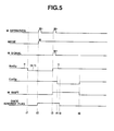
- FIG. 5 is a time chart illustrating the operational error preventing control process according to the embodiment.
- FIG. 5 shows the state in which, when, as the initial condition, the automatic shift mode is selected, and the nth speed is selected, the automatic downshift control to the (n-1)th speed is performed automatically in response to crossing across the downshift line.
- the forced downshift control performed during the selection of the manual shift mode operations are basically the same.
- NxtGP stands for the target speed set by electronic shift control device 15.
- ConGP stands for the actual speed.
- M+ operation stands for the state to turn on the upshift switch 18.
- Mode represents the selection state of selection between the automatic shift mode and the manual shift mode.
- M signal stands for the on signal of upshift switch 18 actually accepted.
- M shift stands for the state in which the shift request is produced on the basis of the M signal.
- nce ignored flag stands for a flag which is set on when a first action of "M+ operation” during the nonintentional shift is ignored, and which is cleared when the nonintentional shift is finished.
- the operating point crosses the downshift line because of a decrease of the vehicle speed, the target speed is set at the (n-1)th speed, and the downshift control is performed from the nth speed to the (n-1)th speed.
- the downshift caused by kickdown instead of the decrease of the vehicle speed.
- a manual upshift operation that is "M+ operation”
- M+ operation is carried out by the driver, and the shift mode is changed from the automatic shift mode to the manual shift mode.
- the downshift control in the automatic shift mode is in progress. Therefore, a first action of "M+ operation” is ignored or disregarded, and the once ignored flag is set on or turned on.
- the control system can nullify or override the first opposite manual operation which is high in possibility of operational error, and perform the shift properly as really desired by the driver. Therefore, the control system can improve the driveability or operability.
- the downshift control started at the time of the automatic shift mode is finished, and hence the actual speed) is brought to the (n-1)th speed.
- the "M shift" is on and the target speed is the nth speed. Therefore, the upshift control is started.
- the once-ignored flag is cleared because of the end of the downshift control.
- the upshift control based on the M signal is finished and hence the actual speed) is brought to the nth speed. Therefore, the target speed) and the actual speed) become equal to each other, the "M shift" is turned off and the shift control is finished.
- the electronic shift control device 1 5 performs an operational error preventing control process in a following manner using an automatic shift mode based on a preset shift map and a manual shift mode based on a driver's manual operation.
- the electronic shift control device 15 forbids a shift based on a first opposite manual operation as shown by a route of step S4 ⁇ step S6, and permits a shift based on a second or subsequent opposite manual operation as shown by a route of step S4 ⁇ step S5.
- the control apparatus or control system can perform the shift of the transmission properly as really desired by the driver, and improve the driveability or operability, by nullifying the shift resulting from the first manual operation which is likely to be operational error or misoperation. Furthermore, since the second or subsequent manual operation is likely to be an actual intention of the driver, the control system permits the shift caused by the second or subsequent manual operation, thereby performs the shift as desired by the driver, and improves the drivearbility or operability.
- the control device 1 5 performs the functional error preventing control process in a following manner.
- the nonintentional upshift is performed because of a quick release of the foot from the accelerator pedal, it is appropriate to assume that the driver has released the accelerator pedal in hope of a deceleration.
- the driver may produce a downshift request with a manual operation to avoid the upshift to obtain an engine braking force. Therefore, the control system performs the operational error preventing control when the upshift command is produced by the manual operation during the nonintentional downshift. By so doing, the control system can perform the shift properly as desired by the driver, and thereby improve the driveability.
- the upshift command is produced by the manual operation during the nonintentional downshift.
- the control system may be arranged so that, when the downshift command is produced by the manual operation during the nonintentional upshift, the shift based on the first manual operation is canceled (forbidden), and the shift based on the second or subsequent manual operation is permitted.
- the forced shift and the automatic shift of the embodiment may be a one-step shift such as a shift from the second speed to the third speed, or may be a jump shift such as a shift from the second speed to the fourth speed.
- the transmission may be a continuously-variable transmission which is equipped with the manual shift mode.
- the control is directed to all types of the nonintentional shift, the control system of the invention may be so arranged that the operational error preventing control process is performed only during a kick-down.
- the control system forbids the upshift, needless to say.
- the operational error preventing control process is performed when the manual upshift operation (M+ operation) is performed during the nonintentional downshift.
- the operational error preventing control process is performed also when the manual upshift operation (M+ operation) is performed during the nonintentional upshift. That is, the control system in this case performs the operational error preventing control process when the manual upshift operation (M+ operation) is performed during the nonintentional shift (regardless whether the upshift or the downshift).
Landscapes
- Engineering & Computer Science (AREA)
- General Engineering & Computer Science (AREA)
- Mechanical Engineering (AREA)
- Control Of Transmission Device (AREA)
- Arrangement Or Mounting Of Control Devices For Change-Speed Gearing (AREA)
Applications Claiming Priority (2)
| Application Number | Priority Date | Filing Date | Title |
|---|---|---|---|
| JP2010193254 | 2010-08-31 | ||
| PCT/JP2011/067729 WO2012029490A1 (fr) | 2010-08-31 | 2011-08-03 | Dispositif de commande de boîte de vitesses automatique |
Publications (4)
| Publication Number | Publication Date |
|---|---|
| EP2613070A1 true EP2613070A1 (fr) | 2013-07-10 |
| EP2613070A4 EP2613070A4 (fr) | 2016-11-02 |
| EP2613070B1 EP2613070B1 (fr) | 2017-11-15 |
| EP2613070B8 EP2613070B8 (fr) | 2018-03-21 |
Family
ID=45772597
Family Applications (1)
| Application Number | Title | Priority Date | Filing Date |
|---|---|---|---|
| EP11821508.6A Active EP2613070B8 (fr) | 2010-08-31 | 2011-08-03 | Dispositif de commande de boîte de vitesses automatique |
Country Status (11)
| Country | Link |
|---|---|
| US (1) | US9234584B2 (fr) |
| EP (1) | EP2613070B8 (fr) |
| JP (1) | JP5383921B2 (fr) |
| KR (1) | KR20130047748A (fr) |
| CN (1) | CN103080614B (fr) |
| BR (1) | BR112013003860B1 (fr) |
| IN (1) | IN2013KN00701A (fr) |
| MX (1) | MX2013001810A (fr) |
| MY (1) | MY167195A (fr) |
| RU (1) | RU2531787C1 (fr) |
| WO (1) | WO2012029490A1 (fr) |
Families Citing this family (5)
| Publication number | Priority date | Publication date | Assignee | Title |
|---|---|---|---|---|
| CN105134942B (zh) * | 2015-08-11 | 2017-08-15 | 上海汽车变速器有限公司 | 强制降挡过程中驾驶意图改变的换挡控制方法 |
| WO2017085828A1 (fr) * | 2015-11-19 | 2017-05-26 | 日産自動車株式会社 | Transmission automatique et son procédé de commande |
| DE102016203763A1 (de) * | 2016-03-08 | 2017-09-14 | Deere & Company | Verfahren und Anordnung zur Steuerung von Fahrzuständen eines Nutzfahrzeugs |
| JP6932988B2 (ja) * | 2017-05-12 | 2021-09-08 | いすゞ自動車株式会社 | 車両制御装置 |
| JP7084816B2 (ja) * | 2018-08-06 | 2022-06-15 | カワサキモータース株式会社 | 変速機付き乗物 |
Family Cites Families (14)
| Publication number | Priority date | Publication date | Assignee | Title |
|---|---|---|---|---|
| JP3168786B2 (ja) | 1993-09-17 | 2001-05-21 | トヨタ自動車株式会社 | 手動変速可能な自動変速機の変速制御装置 |
| JP3435964B2 (ja) * | 1996-03-07 | 2003-08-11 | 日産自動車株式会社 | 自動変速機のマニュアル変速制御装置 |
| JPH1054454A (ja) * | 1996-08-09 | 1998-02-24 | Toyota Motor Corp | 自動変速機の制御装置 |
| JP3725634B2 (ja) * | 1996-09-30 | 2005-12-14 | マツダ株式会社 | 自動変速機の変速操作入力装置 |
| JPH1178617A (ja) * | 1997-09-05 | 1999-03-23 | Nissan Motor Co Ltd | エンジン・自動変速機の総合制御装置 |
| US5984828A (en) * | 1998-03-16 | 1999-11-16 | Meritor Heavy Vehicle Systems, Llc | Control methods for a shift by wire vehicle transmission |
| JP2003083444A (ja) * | 2001-09-11 | 2003-03-19 | Mitsubishi Motors Corp | 自動変速機の変速制御装置 |
| ITTO20011002A1 (it) * | 2001-10-19 | 2003-04-19 | Magneti Marelli Powertrain Spa | Metodo di controllo di una trasmissione automatizzata di un veicolo amotore. |
| DE10391763D2 (de) * | 2002-03-21 | 2005-02-10 | Luk Lamellen & Kupplungsbau | Getriebe und Schaltstrategie für ein Getriebe eines Fahrzeuges |
| JP4200992B2 (ja) * | 2005-08-29 | 2008-12-24 | トヨタ自動車株式会社 | 車両用自動変速機の変速制御装置 |
| US8145399B2 (en) * | 2005-09-08 | 2012-03-27 | Volvo Lastvagnar Ab | Method for instructing a collective gear shift request in a gear box and a method for communicating a gear shift instruction to a gear box |
| JP4811121B2 (ja) | 2006-05-23 | 2011-11-09 | トヨタ自動車株式会社 | 車両用自動変速機の変速制御装置 |
| DE102008042959A1 (de) * | 2008-10-20 | 2010-04-22 | Zf Friedrichshafen Ag | Verfahren zur Steuerung eines Kraftfahrzeug-Antriebsstrangs |
| JP5087111B2 (ja) * | 2010-06-28 | 2012-11-28 | 本田技研工業株式会社 | 自動変速機の制御装置 |
-
2011
- 2011-08-03 EP EP11821508.6A patent/EP2613070B8/fr active Active
- 2011-08-03 US US13/819,161 patent/US9234584B2/en active Active
- 2011-08-03 MY MYPI2013000627A patent/MY167195A/en unknown
- 2011-08-03 WO PCT/JP2011/067729 patent/WO2012029490A1/fr active Application Filing
- 2011-08-03 RU RU2013114268/11A patent/RU2531787C1/ru active
- 2011-08-03 MX MX2013001810A patent/MX2013001810A/es active IP Right Grant
- 2011-08-03 CN CN201180040900.3A patent/CN103080614B/zh active Active
- 2011-08-03 IN IN701KON2013 patent/IN2013KN00701A/en unknown
- 2011-08-03 KR KR1020137004972A patent/KR20130047748A/ko not_active Application Discontinuation
- 2011-08-03 BR BR112013003860-8A patent/BR112013003860B1/pt active IP Right Grant
- 2011-08-03 JP JP2012531764A patent/JP5383921B2/ja active Active
Also Published As
| Publication number | Publication date |
|---|---|
| MY167195A (en) | 2018-08-13 |
| KR20130047748A (ko) | 2013-05-08 |
| RU2013114268A (ru) | 2014-10-10 |
| BR112013003860B1 (pt) | 2020-09-15 |
| CN103080614B (zh) | 2015-11-25 |
| RU2531787C1 (ru) | 2014-10-27 |
| US20130152718A1 (en) | 2013-06-20 |
| CN103080614A (zh) | 2013-05-01 |
| US9234584B2 (en) | 2016-01-12 |
| BR112013003860A2 (pt) | 2016-06-07 |
| EP2613070B1 (fr) | 2017-11-15 |
| EP2613070A4 (fr) | 2016-11-02 |
| JP5383921B2 (ja) | 2014-01-08 |
| IN2013KN00701A (fr) | 2015-04-17 |
| MX2013001810A (es) | 2013-04-29 |
| EP2613070B8 (fr) | 2018-03-21 |
| JPWO2012029490A1 (ja) | 2013-10-28 |
| WO2012029490A1 (fr) | 2012-03-08 |
Similar Documents
| Publication | Publication Date | Title |
|---|---|---|
| US10189475B2 (en) | Vehicle control apparatus | |
| US8738253B2 (en) | Automatic transmission control apparatus, control method, program for realizing that method, and recording medium on which that program is recorded | |
| US7962268B2 (en) | Method and apparatus for manual-mode shifting using voice commands in automobile transmissions | |
| EP2613070B1 (fr) | Dispositif de commande de boîte de vitesses automatique | |
| US9434373B2 (en) | Automatic transmission control device | |
| US20080294317A1 (en) | Method and apparatus to shift-by-speech for semi-manual transmissions with intelligent shifting algorithm | |
| US7447583B2 (en) | Vehicle control apparatus | |
| US5024305A (en) | Method for controlling vehicle transmission systems | |
| JP2009138861A (ja) | 車両統合制御装置 | |
| JP5186742B2 (ja) | 自動変速機のモード切り替え制御装置 | |
| US11879544B2 (en) | Method for avoiding activation of a sailing functionality, a transmission system and a vehicle comprising a transmission system | |
| JP2004513313A (ja) | 自発的な燃料/ペダルオフ時の自動車の自動変速機を制御する方法 | |
| US6003396A (en) | System for controlling downshift points of automatically selectable transmission gears | |
| KR101382240B1 (ko) | 차량의 오토 크루즈 주행시 변속 제어 방법 | |
| KR102244528B1 (ko) | 변속점 이동을 통한 변속 제어 방법 및 장치 | |
| US6689017B2 (en) | Shift control apparatus for an automatic transmission and shift control method for an automatic transmission | |
| JP4409207B2 (ja) | 変速機制御装置 | |
| JP7476594B2 (ja) | 車両の走行制御方法および車両の走行制御装置 | |
| US20040173431A1 (en) | Vehicle brake pedal interlock for heavy vehicle neutral to engaged gear shift | |
| KR101405586B1 (ko) | 오토크루즈 제어방법 | |
| JPH0790726B2 (ja) | 定速走行装置付車両に搭載した自動変速機の変速制御装置 | |
| EP4043712A1 (fr) | Procédé de commande de déplacement à vitesse constante pour véhicule et dispositif de commande de déplacement à vitesse constante pour véhicule | |
| JP2566126Y2 (ja) | 車両用自動変速装置 | |
| JP5186928B2 (ja) | 自動変速機の制御装置および制御方法 | |
| JPH11344107A (ja) | 変速機のシフトダウン制御装置 |
Legal Events
| Date | Code | Title | Description |
|---|---|---|---|
| PUAI | Public reference made under article 153(3) epc to a published international application that has entered the european phase |
Free format text: ORIGINAL CODE: 0009012 |
|
| 17P | Request for examination filed |
Effective date: 20130318 |
|
| AK | Designated contracting states |
Kind code of ref document: A1 Designated state(s): AL AT BE BG CH CY CZ DE DK EE ES FI FR GB GR HR HU IE IS IT LI LT LU LV MC MK MT NL NO PL PT RO RS SE SI SK SM TR |
|
| DAX | Request for extension of the european patent (deleted) | ||
| RA4 | Supplementary search report drawn up and despatched (corrected) |
Effective date: 20160930 |
|
| RIC1 | Information provided on ipc code assigned before grant |
Ipc: F16H 61/16 20060101AFI20160926BHEP |
|
| REG | Reference to a national code |
Ref country code: DE Ref legal event code: R079 Ref document number: 602011043448 Country of ref document: DE Free format text: PREVIOUS MAIN CLASS: F16H0061160000 Ipc: F16H0061020000 |
|
| RIC1 | Information provided on ipc code assigned before grant |
Ipc: F16H 61/02 20060101AFI20170405BHEP Ipc: F16H 61/16 20060101ALI20170405BHEP |
|
| GRAJ | Information related to disapproval of communication of intention to grant by the applicant or resumption of examination proceedings by the epo deleted |
Free format text: ORIGINAL CODE: EPIDOSDIGR1 |
|
| GRAP | Despatch of communication of intention to grant a patent |
Free format text: ORIGINAL CODE: EPIDOSNIGR1 |
|
| INTG | Intention to grant announced |
Effective date: 20170523 |
|
| GRAS | Grant fee paid |
Free format text: ORIGINAL CODE: EPIDOSNIGR3 |
|
| GRAA | (expected) grant |
Free format text: ORIGINAL CODE: 0009210 |
|
| AK | Designated contracting states |
Kind code of ref document: B1 Designated state(s): AL AT BE BG CH CY CZ DE DK EE ES FI FR GB GR HR HU IE IS IT LI LT LU LV MC MK MT NL NO PL PT RO RS SE SI SK SM TR |
|
| REG | Reference to a national code |
Ref country code: CH Ref legal event code: EP Ref country code: GB Ref legal event code: FG4D Ref country code: AT Ref legal event code: REF Ref document number: 946613 Country of ref document: AT Kind code of ref document: T Effective date: 20171115 |
|
| REG | Reference to a national code |
Ref country code: IE Ref legal event code: FG4D |
|
| REG | Reference to a national code |
Ref country code: DE Ref legal event code: R096 Ref document number: 602011043448 Country of ref document: DE |
|
| RAP2 | Party data changed (patent owner data changed or rights of a patent transferred) |
Owner name: JATCO LTD Owner name: NISSAN MOTOR CO., LTD. |
|
| REG | Reference to a national code |
Ref country code: NL Ref legal event code: MP Effective date: 20171115 |
|
| REG | Reference to a national code |
Ref country code: LT Ref legal event code: MG4D |
|
| REG | Reference to a national code |
Ref country code: AT Ref legal event code: MK05 Ref document number: 946613 Country of ref document: AT Kind code of ref document: T Effective date: 20171115 |
|
| PG25 | Lapsed in a contracting state [announced via postgrant information from national office to epo] |
Ref country code: NO Free format text: LAPSE BECAUSE OF FAILURE TO SUBMIT A TRANSLATION OF THE DESCRIPTION OR TO PAY THE FEE WITHIN THE PRESCRIBED TIME-LIMIT Effective date: 20180215 Ref country code: ES Free format text: LAPSE BECAUSE OF FAILURE TO SUBMIT A TRANSLATION OF THE DESCRIPTION OR TO PAY THE FEE WITHIN THE PRESCRIBED TIME-LIMIT Effective date: 20171115 Ref country code: SE Free format text: LAPSE BECAUSE OF FAILURE TO SUBMIT A TRANSLATION OF THE DESCRIPTION OR TO PAY THE FEE WITHIN THE PRESCRIBED TIME-LIMIT Effective date: 20171115 Ref country code: LT Free format text: LAPSE BECAUSE OF FAILURE TO SUBMIT A TRANSLATION OF THE DESCRIPTION OR TO PAY THE FEE WITHIN THE PRESCRIBED TIME-LIMIT Effective date: 20171115 Ref country code: FI Free format text: LAPSE BECAUSE OF FAILURE TO SUBMIT A TRANSLATION OF THE DESCRIPTION OR TO PAY THE FEE WITHIN THE PRESCRIBED TIME-LIMIT Effective date: 20171115 Ref country code: NL Free format text: LAPSE BECAUSE OF FAILURE TO SUBMIT A TRANSLATION OF THE DESCRIPTION OR TO PAY THE FEE WITHIN THE PRESCRIBED TIME-LIMIT Effective date: 20171115 |
|
| PG25 | Lapsed in a contracting state [announced via postgrant information from national office to epo] |
Ref country code: LV Free format text: LAPSE BECAUSE OF FAILURE TO SUBMIT A TRANSLATION OF THE DESCRIPTION OR TO PAY THE FEE WITHIN THE PRESCRIBED TIME-LIMIT Effective date: 20171115 Ref country code: RS Free format text: LAPSE BECAUSE OF FAILURE TO SUBMIT A TRANSLATION OF THE DESCRIPTION OR TO PAY THE FEE WITHIN THE PRESCRIBED TIME-LIMIT Effective date: 20171115 Ref country code: AT Free format text: LAPSE BECAUSE OF FAILURE TO SUBMIT A TRANSLATION OF THE DESCRIPTION OR TO PAY THE FEE WITHIN THE PRESCRIBED TIME-LIMIT Effective date: 20171115 Ref country code: BG Free format text: LAPSE BECAUSE OF FAILURE TO SUBMIT A TRANSLATION OF THE DESCRIPTION OR TO PAY THE FEE WITHIN THE PRESCRIBED TIME-LIMIT Effective date: 20180215 Ref country code: HR Free format text: LAPSE BECAUSE OF FAILURE TO SUBMIT A TRANSLATION OF THE DESCRIPTION OR TO PAY THE FEE WITHIN THE PRESCRIBED TIME-LIMIT Effective date: 20171115 Ref country code: GR Free format text: LAPSE BECAUSE OF FAILURE TO SUBMIT A TRANSLATION OF THE DESCRIPTION OR TO PAY THE FEE WITHIN THE PRESCRIBED TIME-LIMIT Effective date: 20180216 |
|
| PG25 | Lapsed in a contracting state [announced via postgrant information from national office to epo] |
Ref country code: DK Free format text: LAPSE BECAUSE OF FAILURE TO SUBMIT A TRANSLATION OF THE DESCRIPTION OR TO PAY THE FEE WITHIN THE PRESCRIBED TIME-LIMIT Effective date: 20171115 Ref country code: CY Free format text: LAPSE BECAUSE OF FAILURE TO SUBMIT A TRANSLATION OF THE DESCRIPTION OR TO PAY THE FEE WITHIN THE PRESCRIBED TIME-LIMIT Effective date: 20171115 Ref country code: EE Free format text: LAPSE BECAUSE OF FAILURE TO SUBMIT A TRANSLATION OF THE DESCRIPTION OR TO PAY THE FEE WITHIN THE PRESCRIBED TIME-LIMIT Effective date: 20171115 Ref country code: SK Free format text: LAPSE BECAUSE OF FAILURE TO SUBMIT A TRANSLATION OF THE DESCRIPTION OR TO PAY THE FEE WITHIN THE PRESCRIBED TIME-LIMIT Effective date: 20171115 Ref country code: CZ Free format text: LAPSE BECAUSE OF FAILURE TO SUBMIT A TRANSLATION OF THE DESCRIPTION OR TO PAY THE FEE WITHIN THE PRESCRIBED TIME-LIMIT Effective date: 20171115 |
|
| REG | Reference to a national code |
Ref country code: DE Ref legal event code: R097 Ref document number: 602011043448 Country of ref document: DE |
|
| REG | Reference to a national code |
Ref country code: FR Ref legal event code: PLFP Year of fee payment: 8 |
|
| PG25 | Lapsed in a contracting state [announced via postgrant information from national office to epo] |
Ref country code: SM Free format text: LAPSE BECAUSE OF FAILURE TO SUBMIT A TRANSLATION OF THE DESCRIPTION OR TO PAY THE FEE WITHIN THE PRESCRIBED TIME-LIMIT Effective date: 20171115 Ref country code: RO Free format text: LAPSE BECAUSE OF FAILURE TO SUBMIT A TRANSLATION OF THE DESCRIPTION OR TO PAY THE FEE WITHIN THE PRESCRIBED TIME-LIMIT Effective date: 20171115 Ref country code: PL Free format text: LAPSE BECAUSE OF FAILURE TO SUBMIT A TRANSLATION OF THE DESCRIPTION OR TO PAY THE FEE WITHIN THE PRESCRIBED TIME-LIMIT Effective date: 20171115 |
|
| PLBE | No opposition filed within time limit |
Free format text: ORIGINAL CODE: 0009261 |
|
| STAA | Information on the status of an ep patent application or granted ep patent |
Free format text: STATUS: NO OPPOSITION FILED WITHIN TIME LIMIT |
|
| 26N | No opposition filed |
Effective date: 20180817 |
|
| PGFP | Annual fee paid to national office [announced via postgrant information from national office to epo] |
Ref country code: FR Payment date: 20180712 Year of fee payment: 16 |
|
| PG25 | Lapsed in a contracting state [announced via postgrant information from national office to epo] |
Ref country code: SI Free format text: LAPSE BECAUSE OF FAILURE TO SUBMIT A TRANSLATION OF THE DESCRIPTION OR TO PAY THE FEE WITHIN THE PRESCRIBED TIME-LIMIT Effective date: 20171115 |
|
| PG25 | Lapsed in a contracting state [announced via postgrant information from national office to epo] |
Ref country code: MC Free format text: LAPSE BECAUSE OF FAILURE TO SUBMIT A TRANSLATION OF THE DESCRIPTION OR TO PAY THE FEE WITHIN THE PRESCRIBED TIME-LIMIT Effective date: 20171115 |
|
| REG | Reference to a national code |
Ref country code: CH Ref legal event code: PL |
|
| PG25 | Lapsed in a contracting state [announced via postgrant information from national office to epo] |
Ref country code: LI Free format text: LAPSE BECAUSE OF NON-PAYMENT OF DUE FEES Effective date: 20180831 Ref country code: CH Free format text: LAPSE BECAUSE OF NON-PAYMENT OF DUE FEES Effective date: 20180831 Ref country code: LU Free format text: LAPSE BECAUSE OF NON-PAYMENT OF DUE FEES Effective date: 20180803 |
|
| REG | Reference to a national code |
Ref country code: BE Ref legal event code: MM Effective date: 20180831 |
|
| REG | Reference to a national code |
Ref country code: IE Ref legal event code: MM4A |
|
| PG25 | Lapsed in a contracting state [announced via postgrant information from national office to epo] |
Ref country code: IE Free format text: LAPSE BECAUSE OF NON-PAYMENT OF DUE FEES Effective date: 20180803 |
|
| PG25 | Lapsed in a contracting state [announced via postgrant information from national office to epo] |
Ref country code: BE Free format text: LAPSE BECAUSE OF NON-PAYMENT OF DUE FEES Effective date: 20180831 |
|
| REG | Reference to a national code |
Ref country code: DE Ref legal event code: R082 Ref document number: 602011043448 Country of ref document: DE Representative=s name: GRUENECKER PATENT- UND RECHTSANWAELTE PARTG MB, DE Ref country code: DE Ref legal event code: R081 Ref document number: 602011043448 Country of ref document: DE Owner name: NISSAN MOTOR CO., LTD., YOKOHAMA-SHI, JP Free format text: FORMER OWNERS: JATCO LTD, FUJI-SHI, SHIZUOKA-KEN, JP; NISSAN MOTOR CO., LTD., YOKOHAMA-SHI, KANAGAWA, JP |
|
| PG25 | Lapsed in a contracting state [announced via postgrant information from national office to epo] |
Ref country code: MT Free format text: LAPSE BECAUSE OF NON-PAYMENT OF DUE FEES Effective date: 20180803 |
|
| PG25 | Lapsed in a contracting state [announced via postgrant information from national office to epo] |
Ref country code: TR Free format text: LAPSE BECAUSE OF FAILURE TO SUBMIT A TRANSLATION OF THE DESCRIPTION OR TO PAY THE FEE WITHIN THE PRESCRIBED TIME-LIMIT Effective date: 20171115 |
|
| PG25 | Lapsed in a contracting state [announced via postgrant information from national office to epo] |
Ref country code: HU Free format text: LAPSE BECAUSE OF FAILURE TO SUBMIT A TRANSLATION OF THE DESCRIPTION OR TO PAY THE FEE WITHIN THE PRESCRIBED TIME-LIMIT; INVALID AB INITIO Effective date: 20110803 Ref country code: PT Free format text: LAPSE BECAUSE OF FAILURE TO SUBMIT A TRANSLATION OF THE DESCRIPTION OR TO PAY THE FEE WITHIN THE PRESCRIBED TIME-LIMIT Effective date: 20171115 |
|
| PG25 | Lapsed in a contracting state [announced via postgrant information from national office to epo] |
Ref country code: MK Free format text: LAPSE BECAUSE OF NON-PAYMENT OF DUE FEES Effective date: 20171115 |
|
| PG25 | Lapsed in a contracting state [announced via postgrant information from national office to epo] |
Ref country code: AL Free format text: LAPSE BECAUSE OF FAILURE TO SUBMIT A TRANSLATION OF THE DESCRIPTION OR TO PAY THE FEE WITHIN THE PRESCRIBED TIME-LIMIT Effective date: 20171115 Ref country code: IS Free format text: LAPSE BECAUSE OF FAILURE TO SUBMIT A TRANSLATION OF THE DESCRIPTION OR TO PAY THE FEE WITHIN THE PRESCRIBED TIME-LIMIT Effective date: 20180315 |
|
| PG25 | Lapsed in a contracting state [announced via postgrant information from national office to epo] |
Ref country code: IT Free format text: LAPSE BECAUSE OF NON-PAYMENT OF DUE FEES Effective date: 20190803 |
|
| PGFP | Annual fee paid to national office [announced via postgrant information from national office to epo] |
Ref country code: DE Payment date: 20240723 Year of fee payment: 14 |
|
| PGFP | Annual fee paid to national office [announced via postgrant information from national office to epo] |
Ref country code: GB Payment date: 20240723 Year of fee payment: 14 |