EP2612792A1 - Kindersitz - Google Patents
Kindersitz Download PDFInfo
- Publication number
- EP2612792A1 EP2612792A1 EP13150122.3A EP13150122A EP2612792A1 EP 2612792 A1 EP2612792 A1 EP 2612792A1 EP 13150122 A EP13150122 A EP 13150122A EP 2612792 A1 EP2612792 A1 EP 2612792A1
- Authority
- EP
- European Patent Office
- Prior art keywords
- sliding member
- engagement
- back plate
- seat
- plate part
- Prior art date
- Legal status (The legal status is an assumption and is not a legal conclusion. Google has not performed a legal analysis and makes no representation as to the accuracy of the status listed.)
- Granted
Links
- 230000002265 prevention Effects 0.000 description 12
- 239000000470 constituent Substances 0.000 description 5
- 239000011295 pitch Substances 0.000 description 3
- 210000001217 buttock Anatomy 0.000 description 2
- 238000006073 displacement reaction Methods 0.000 description 2
- 230000005484 gravity Effects 0.000 description 1
- 239000002184 metal Substances 0.000 description 1
- 230000004048 modification Effects 0.000 description 1
- 238000012986 modification Methods 0.000 description 1
- 238000009751 slip forming Methods 0.000 description 1
- 210000000689 upper leg Anatomy 0.000 description 1
Images


Classifications
-
- B—PERFORMING OPERATIONS; TRANSPORTING
- B60—VEHICLES IN GENERAL
- B60N—SEATS SPECIALLY ADAPTED FOR VEHICLES; VEHICLE PASSENGER ACCOMMODATION NOT OTHERWISE PROVIDED FOR
- B60N2/00—Seats specially adapted for vehicles; Arrangement or mounting of seats in vehicles
- B60N2/24—Seats specially adapted for vehicles; Arrangement or mounting of seats in vehicles for particular purposes or particular vehicles
- B60N2/26—Seats specially adapted for vehicles; Arrangement or mounting of seats in vehicles for particular purposes or particular vehicles for children
- B60N2/265—Adaptations for seat belts
-
- B—PERFORMING OPERATIONS; TRANSPORTING
- B60—VEHICLES IN GENERAL
- B60N—SEATS SPECIALLY ADAPTED FOR VEHICLES; VEHICLE PASSENGER ACCOMMODATION NOT OTHERWISE PROVIDED FOR
- B60N2/00—Seats specially adapted for vehicles; Arrangement or mounting of seats in vehicles
- B60N2/24—Seats specially adapted for vehicles; Arrangement or mounting of seats in vehicles for particular purposes or particular vehicles
- B60N2/26—Seats specially adapted for vehicles; Arrangement or mounting of seats in vehicles for particular purposes or particular vehicles for children
- B60N2/28—Seats readily mountable on, and dismountable from, existing seats or other parts of the vehicle
- B60N2/2803—Adaptations for seat belts
- B60N2/2812—Adaptations for seat belts for securing the child to the child seat
-
- B—PERFORMING OPERATIONS; TRANSPORTING
- B60—VEHICLES IN GENERAL
- B60N—SEATS SPECIALLY ADAPTED FOR VEHICLES; VEHICLE PASSENGER ACCOMMODATION NOT OTHERWISE PROVIDED FOR
- B60N2/00—Seats specially adapted for vehicles; Arrangement or mounting of seats in vehicles
- B60N2/24—Seats specially adapted for vehicles; Arrangement or mounting of seats in vehicles for particular purposes or particular vehicles
- B60N2/26—Seats specially adapted for vehicles; Arrangement or mounting of seats in vehicles for particular purposes or particular vehicles for children
- B60N2/28—Seats readily mountable on, and dismountable from, existing seats or other parts of the vehicle
- B60N2/2851—Seats readily mountable on, and dismountable from, existing seats or other parts of the vehicle provided with head-rests
-
- B—PERFORMING OPERATIONS; TRANSPORTING
- B60—VEHICLES IN GENERAL
- B60N—SEATS SPECIALLY ADAPTED FOR VEHICLES; VEHICLE PASSENGER ACCOMMODATION NOT OTHERWISE PROVIDED FOR
- B60N2/00—Seats specially adapted for vehicles; Arrangement or mounting of seats in vehicles
- B60N2/58—Seat coverings
- B60N2/60—Removable protective coverings
Definitions
- the present invention relates to a child car seat on which a child is seated. More particularly, the present invention relates to a child car seat including a child belt for fixing a child.
- a child car seat that is fixed on a seat of a vehicle by means of a vehicle seatbelt is generally known as a child car seat having a child belt for fixing a child.
- the child belt includes a crotch belt passing through between thighs of a child, and shoulder belts extending on shoulders.
- a plurality of through-holes through which the shoulder belt can pass are formed in a back part of the child car seat at different positions in a height direction.
- the present invention has been made in view of the above circumstances.
- the object of the present invention is to provide a child car seat in which a position of a child belt can be easily adjusted.
- a child car seat according to the present invention is a child car seat comprising:
- the sliding member may constitute a headrest.
- At least one of the through-hole and the elongate hole may include a pair of holes that are spaced apart from each other in a width direction.
- the child car seat according to the present invention may further include further comprising a fixing device joined to the sliding member through the elongate hole of the back plate part, such that the back plate part is sandwiched between the fixing device and the sliding member, wherein the fixing device is slidable, together with the sliding member, with respect to the back plate part.
- the elongate hole may include a pair of elongate holes that are spaced apart from each other in a width direction; and the fixing device may extend in the width direction and may be joined to the sliding member through both of the elongate holes.
- one of the sliding member and the seat part may include a pair of engagement parts that are spaced apart from each other in a width direction, each engagement part extending in the sliding direction of the sliding member with respect to the back plate part; the other of the sliding member and the seat part may include a pair of engagement pieces that are spaced apart from each other in the width direction, the engagement pieces being capable of moving away from each other and moving closer to each other; and a sliding movement of the sliding member with respect to the back plate part may be restricted, by engaging the engagement piece with the engagement part.
- the pair of engagement parts may be disposed on the back plate part; the pair of engagement pieces may be disposed on the sliding member; and the pair of engagement pieces may be engaged with the engagement parts located on positions opposed to the respective engagement pieces from outside in the width direction, when the engagement pieces are moved away from each other outward in the width direction.
- one of the sliding member and the seat part may have an engagement part extending in the sliding direction of the sliding member with respect to the back plate part; the other of the sliding member and the seat part may have an engagement piece at a position opposed to the engagement part, the engagement piece being supported to be capable of moving closer to and moving away from the one of the sliding member and the seat part; and a sliding movement of the sliding member with respect to the back plate part may be restricted, by engaging the engagement piece with the engagement part.
- the elongate hole may include a pair of elongate holes disposed in the back plate part, the elongate holes being spaced apart from each other in a width direction; and the engagement part may be located on a position between the pair of elongate holes of the back plate part in the width direction.
- a pair of first engagement parts that are spaced apart from each other in a width direction may be disposed on the sliding member or the seat part, each engagement part extending in the sliding direction of the sliding member with respect to the back plate part, and a pair of first engagement pieces that are spaced apart from each other in the width direction are disposed on one of the sliding member and the seat part on which the first engagement parts are not disposed, the first engagement pieces being capable of moving away from each other and moving closer to each other;
- a second engagement part extending in the sliding direction of the sliding member with respect to the back plate part may be disposed on the sliding member or the seat part, and a second engagement piece is disposed, at a position opposed to the second engagement part, on one of the sliding member and the seat part on which the second engagement part is not disposed, the second engagement piece being supported to be capable of moving closer to and moving away from one of the the sliding member and the seat part on which the second engagement part is disposed; and a sliding movement of the sliding member with
- the child car seat according to the present invention may further include an operation member disposed on the sliding member, the operation member being slidable with respect to the sliding member along the sliding direction of the sliding member with respect to the back plate part, wherein a sliding movement of the sliding member with respect to the back plate part may be enabled, by sliding the operation member with respect to the sliding member.
- the operation member is arranged between the sliding member and the back plate part, and the operation member may have a gripping part exposed from the sliding member.
- the child car seat according to the present invention may further include a cover member for seat to be set on the seat part, wherein: an opening may be formed in the cover member for seat, at a position opposed to the back plate part from the front side; and the sliding member may be passed through the opening.
- a position of the child belt provided on the child car seat can be easily adjusted.
- Figs. 1 to 14 are views for explaining one embodiment of the present invention.
- the illustrated child car seat 10 according to this embodiment is located on a seat 5 of a vehicle, e.g., an automobile, so as to be used.
- the child car seat 10 is an apparatus for safely letting a child (such as an infant or a baby) to ride thereon in a vehicle including a seat (vehicle seat 5) and a seatbelt 7 that are designed for an adult.
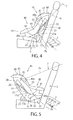
- the child car seat 10 explained herein can be mounted on the seat 5 in a "forward-facing condition" in which a child seated on a seat part 40 faces forward of the car, which is shown in Fig. 4 , and in a "rearward-facing condition" in which the child seated on the seat part 40 faces rearward of the car, which is shown in Fig. 5 .
- the terms “front”, “rear (back)”, “right”, “left”, “lateral”, “up” and “down” used for the child car seat 10 and its constituent elements mean, unless otherwise specified, “front”, “rear”, “right”, “left”, “lateral”, “up” and “down”, with respect to a child seated on the child car seat 10 in the forward-facing condition shown in Fig. 4 , respectively.
- a “width direction” of the child car seat 10 and its constituent elements means a direction connecting the "left” and “right”, i.e., the "lateral direction”.
- a “height direction” of the child car seat 10 and its constituent elements mean the "up and down direction”.
- a "back and fourth" direction of the child car seat 10 and its constituent elements means a direction connecting the “front” and the "back".
- the "back and front” direction corresponds to the “back and front direction” or the “traveling direction” of the vehicle.
- the child car seat 10 includes a child-car-seat body 15 having a seat part (seat body) 40 composed of a seat plate part 41 and a back plate part 45, a sliding member 60 located on a position opposed to the back plate part 45 from the front side, and a child belt 30 disposed on the child-car-seat body 15.
- the sliding member 60 can be slid with respect to the back plate part 45 so as to be movable in the height direction.
- the sliding member 60 has a through-hole 66 through which the child belt 30 can pass.
- an elongate hole 46 extending in a direction in which the sliding member 60 slides (sliding direction of the sliding member 60) with respect to the back plate part 45.
- the child belt 30 having passed through the through-hole 66 of the sliding member 60 also passes through the elongate hole 46.
- the sliding member 60 is constituted as a headrest for receiving a head of a child seated on the child car seat 10.
- the sliding member 60 is constituted as a headrest for receiving a head of a child seated on the child car seat 10.
- a first engagement part 51 which extends in the sliding direction of the sliding member 60 with respect to the back plate part 45, is disposed on one of the sliding member 60 and the back plate part 45, and a first engagement piece 71, which is capable of being engaged with the first engagement part 51, is disposed on the other on which the first engagement part 51 is not disposed.
- a second engagement part 52 which extends in the sliding direction of the sliding member 60 with respect to the back plate part 45, is disposed on one of the sliding member 60 and the back plate part 45, and a second engagement piece 72, which is capable of being engaged with the second engagement part 52, is disposed on the other on which the second engagement member 52 is not disposed.
- the child car seat 10 is provided with an operation member 80 for operating the engagement and the disengagement between the first engagement part 51 and the first engagement piece 71, and the engagement and the disengagement between the second engagement part 52 and the second engagement piece 72.
- the operation member 80 is disposed between the sliding member 60 and the back plate part 45 of the seat part 40.
- the operation member 80 is supported, by the sliding member 60, slidably with respect to the sliding member 60.
- a fixing device (rear-surface fixing device) 55 is disposed on a rear part of the back plate part 45 of the seat part 40.
- the fixing device 55 is joined to the sliding member 55 through the elongate hole 46. Namely, in an arrangement where the back plate part 45 is sandwiched between the sliding member 60 and the fixing device 55, the sliding member 60 is disposed slidably with respect to the back plate part 45 of the seat part 40 by means of the fixing device 55.
- a cover member 11 for seat part is removably arranged on the seat part 40 of the child-car-seat body 15, and a cover member 12 for headrest is removably arranged on the sliding member 60.
- the cover member 11 for seat part has an opening 11a at a position of the cover member 11 for seat part opposed to the back plate part 45 from the front side.
- the sliding member 60 is located through the opening 11a.
- a hole through which the child belt 30 can be inserted is formed at a position of the cover member 12 for headrest opposed to the through-hole 66 of the sliding member 60.
- the cover member 11 for seat part and the cover member 12 for headrest are shown only in Figs. 1 to 3 , and illustration thereof is omitted in the other drawings.
- the child car seat 10 in this embodiment has a substantially symmetrical structure as a whole, about a surface along the back and front direction (laterally central surface) which passes a center of the width direction (lateral direction).
- the child-car-seat body 15 is described at first. As shown in Figs. 1 to 5 , the child-car-seat body 15 includes the seat part (seat body) 40 having the seat plate part 41 and the back plate part 45, and a base 16 fixed on the seat part 40. the seat part 40 is a place on which a child is seated. On the other hand, when the child car seat 10 is set on the seat 5 of a vehicle, the base 16 is located between the seat part 40 on which a child is seated, and the seat 5 of the vehicle, such that the base 16 is in contact with the seat 5.
- the base 16 includes a rear base 20 positioned behind the seat part 40, and a lower base 25 positioned below the seat part 40. As shown in Fig. 3 , there are provided a pair of the rear bases 20 that are spaced apart from each other in the width direction. Each rear base 20 has a rear base through-hole 21 extending substantially in the up and down direction. A belt gripper 22 for gripping a vehicle seatbelt 7 is disposed above each through-hole 21. Below the through-hole 21, there is formed a belt leading part 21a structured as a groove for leading the vehicle seatbelt 7. On the other hand, in the lower base 25, there are formed a pair of the belt leading parts 26a structured as grooves for leading the vehicle seatbelt 7, such that the pair of belt leading parts 26a are spaced apart from each other in the width direction.
- the vehicle seatbelt 7 is a seatbelt of a so-called three-point type, including a shoulder belt 7a extending from a shoulder on one side (e.g., right side) to a waist on the other side (e.g., left side), and a waist belt 7b extending from the waist on one side to the waist on the other side.
- the seatbelt 7 further includes a buckle 7c, which is inserted through one belt-like member to bend the one belt-like member so as to define the shoulder belt 7a and the waist belt 7b, and a receiving buckle 7d disposed on the other side of the seat 5. By locking the buckle 7c on the receiving buckle 7d, the body of a person seated on the seat 5 can be fixed on the seat 5.
- the shoulder belt 7a of the vehicle seatbelt 7 is supported by the belt leading part 21a on one side, while the shoulder belt 7a being gripped by the belt gripper 22 on the other side (e.g., left side).
- the waist belt 7b is supported by the belt leading parts 21a on both sides.
- the buckle 7c is fastened on the receiving buckle 7d.
- the shoulder belt 7a and the waist belt 7b of the vehicle seatbelt 7 are supported by the belt leading parts 26a on both sides.
- a side plate part 43 of the seat part 40 which will be described later, is provided with a belt leading device 43a that receives the shoulder belt 7a.
- an auxiliary support piece 17 is disposed below each rear base 20, such that the auxiliary support piece 17 can be swung about a swing axis 17a.
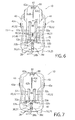
- a swing axis 17a As shown in Fig. 5 , when the child car seat 10 is mounted in the rearward-facing condition on the seat 5 of the vehicle, an inclination angle of the child car seat 10 is adjusted by using the auxiliary support piece 17 that is swung to extend from the rear base 20.
- the auxiliary support piece 17 is not used. At this time, the auxiliary support piece 17 is accommodated in the base 16 so as not to protrude from the rear base 20 and the lower base 25.
- the auxiliary support piece 17 When the auxiliary support piece 17 is housed in the rear base 20 and the lower base 25, the auxiliary support piece 17 is positioned in a lower-base through-hole 26 which is used for fixing the child car seat 10 in the rearward-facing condition. Thus, if one fails to deploy the auxiliary support piece 17 when the child car seat 10 is mounted in the rear-ward facing condition in the seat 5 of the vehicle, a part of the lower-base through-hole 26, through which the buckle 7c of the vehicle seatbelt 7 should passes, is closed by the auxiliary support piece 17, which shown in Fig. 4 . Thus, when the child car seat 10 is fixed in the rearward-facing condition, the failure in using the auxiliary support piece 17 can be effectively prevented, and the adequate use of the auxiliary support piece 17 is promoted.
- the seat part 40 is a member that is disposed on the base 16 so as to receive a child thereon.
- the seat part 40 includes the seat plate part (seat part, buttock part) 41 that receives buttocks of a child, the back plate part (back part) 45 that stands up from a rear part of the seat plate part 41 for receiving a back of the child, and the side plate parts (side parts) 43 disposed on both sides of the back plate part 41 and the rear plate part 45.
- the side plate parts 43 support a child seated on the child car seat 10 from the lateral sides.
- the belt leading devices 43a for leading the vehicle seatbelt 7 are disposed on both sides of each side plate part 43.
- the back plate part 45 located behind the sliding member 60 includes a pair of fixed rail members 48 that are spaced apart from each other in the width direction.
- the pair of rail members 48 are arranged in parallel with each other.
- each rail member 48 extends along the longitudinal direction of the back plate part 45, in other words, along a direction perpendicular to the width direction.
- the rail member 48 is arranged to be slidable with respect to the sliding member 60.
- each rail member 48 includes an elongated rail-member body 48a and a flange part 48c extending from the rail-member body 48a to the inside in the width direction.
- the flange part 48c extends in the longitudinal direction of the rail-member body 48a.
- recesses 48b opened toward the inside in the width direction are continuously formed in the longitudinal direction of the rail member 48.
- a number of recesses 48b constitute the first engagement part 51 which can restrict the sliding movement of the sliding member 60, by being engaged with the first engagement piece 71 disposed on the sliding member 60.
- each elongate hole 46 extends along the sliding direction of the sliding member 60 with respect to the back plate part 45, i.e., along the longitudinal direction of the rail member 48.
- the elongate holes 46 are adapted to be opposed to the through-holes 66 of the sliding member 60.
- the child belt 30 can pass through both the through-holes 66 of the sliding member 60 and the elongate holes 46 of the back plate part 45.
- a rugged part (patterned raised part) along the sliding direction of the sliding member 60 with respect to the back plate part 45, i.e., along the longitudinal direction of the rail member 48.
- the rugged part is formed by a number of locking projections 49 that are arranged along the sliding direction of the sliding member 60 with respect to the back plate part 45.
- the respective locking projections 49 extending in the width direction are arranged at predetermined pitches therebetween in the sliding direction of the sliding member 60 with respect to the back plate part 45.
- the rugged part defined by the plurality of locking projections 49 constitutes the second engagement part 52 which can restrict the sliding movement of the sliding member 60, by being engaged with the second engagement piece 72 disposed on the sliding member 60.
- the back plate part 45 has a forwardly projecting escape prevention piece 47 having an enlarged head.
- the escape prevention piece 47 is engaged with a below-described leading elongate hole 62b of the sliding member 60, so as to prevent that the sliding member 60 is disengaged from the back plate part 45.
- the leading elongate hole 62b of the sliding member 60 extends along the sliding direction of the sliding member 60 with respect to the back plate part 45.
- a width of the leading elongate hole 62b is smaller than a width of the head of the escape prevention piece 47.
- an end hole 62c is formed in an upper end of the leading elongate hole 62b of the sliding member 60.
- a width of the end hole 62 is larger than that of the leading elongate hole 62b.
- the escape prevention piece 47 can be engaged with the leading elongate hole 62b. Meanwhile, the escape prevention piece 47 is located on a position near to the end hole 62c.
- the child car seat 10 can be assembled in the following manner. That is to say, before the escape prevention piece 47 is fixed on the back plate part 45, the sliding member 60 is mounted on the seat part 40. Thereafter, the escape prevention piece 47 is fixed on the back plate part 45 such that the escape prevention piece 47 is engaged with the leading elongate hole 62b through the wider end hole 62c.
- the child belt 30 is described.
- the child car seat 10 herein described is fixed on the seat 5 of the vehicle by the seatbelt 7 of the vehicle, and a body of a child seated on the child car seat 10 is fixed thereon by the dedicated child belt 30.
- the child belt 30 is disposed on the seat part 40.
- the child belt 30 may be structured as a belt of a three-point type including a crotch belt and shoulder belts, or as a belt of a five-point type including a crotch belt, a waist belt and shoulder belts.
- the child belt 30 structured as a belt of a five-point type is described.
- the child belt 30 includes a first belt 31 functioning as a crotch belt, and a second belt 32 functioning as waist belts 32b and shoulder belts 32c.
- One end of the first belt 31 is fixed on substantially a center of the seat plate part 41, and a first buckle 31a is disposed on the other end of the first belt 31.
- the second belts 32 shown in Fig. 8 may be joined to each other in the inside of the seat plate part 41 or on the rear side thereof.
- Each second belt 32 extends through a second buckle 32a. As shown in Figs. 1 and 2 , the second belt 32 is folded up (turned up) by the second buckle 32a so as to define the waist belt 32b and the shoulder belt 32c.
- an end of the second belt 32 on the side of the shoulder belt 32c passes through the through-hole 66 of the sliding member 60 and the elongate hole 46 of the back plate part 45 so as to be joined to a belt-length adjusting mechanism 28.
- the belt-length adjusting mechanism 28 incudes a connection attachment 28a on which the shoulder belt 32 is fixed, an adjusting belt 28b joined to the connection attachment 28a and an adjusting belt chuck 28c disposed on the front part of the seat plate part 41.
- the adjusting belt chuck 28c openably grips the adjusting belt 28b.
- a child seated on the child car seat 10 can be fixed on the child car seat 10, by adjusting the lengths of the waist belt 32b and the shoulder belt 32c by means of the belt-length adjusting mechanism 28, and by locking the second buckle 32a by the first buckle 31a.
- the sliding member 60 includes a body plate 61 opposed to the seat part 40 from the front side, a fixed member 73 and a swinging member 75 which are disposed on the body plate 61. As described above, the sliding member 60 does not only support the shoulder belts 32c of the child belt 30 but also functions as a headrest covered with the cover member 12 for headrest. Between the body plate 61 and the seat part 40, there is provided the operation member 80 slidably supported on the sliding member 60.
- the body plate 61 includes a back part 61a located on a position opposed to the back plate part 45 of the seat part 40, and a pair of side parts 61b disposed on both lateral sides of the back part 61a on positions opposed to the side plate parts 43 of the seat part 40.
- the aforementioned through-holes 66, the leading elongate hole 62bc and the end hole 62c are formed in the back part 61a of the body plate 61.
- a pair of the through-holes 66 are formed on positions that are spaced apart from each other in the width direction.
- an exposure hole 62a from which the operation member 80 is exposed.
- the cover member 12 for headrest is formed to expose the exposure hole 62a.
- a pair of guide projections 63 that are spaced apart from each other in the width direction.
- the respective guide projections 63a extend along both side edges of the back part 61 in the width direction, in the sliding direction of the sliding member 60 with respect to the back plate part 45.
- the guide projection 63 protrudes rearward from the body plate 61, i.e., toward the side of the back plate part 45 of the seat part 40.
- Each guide projection 63 comes into contact with the rail member 48 located on a predetermined position with respect to the sliding member 60 from the outside in the width direction, so as to guide the sliding movement of the sliding member 60 with respect to the back plate part 45 of the seat part 40 on which the rail member 48 is fixed.
- each swinging member 75 includes a fixed part 75a that is fixed on the back part 61a by means of an attachment member 75c such as a screw, and a swinging part 75b extending from the fixed part 75a. As shown in Figs. 9 to 11 , each swinging member 75 is located on a position opposed to the rail member 48 from the inside in the width direction.
- the swinging part 75b is swingable with respect to the fixed part 75a fixed to the body plate 61.
- Each swinging part 75b can be moved between a position at which the swinging member 75b is located outward in the width direction so as to be in contact with the rail member 48, and a position at which the swinging member 75b is located inward in the width direction so as to be distant from the rail member 48.
- the swinging movement of each swinging part 75b is achieved as a resilient deformation with respect to the fixed part 75a.
- the swinging part 75b can be located on an inward position in the width direction, which is shown in Fig. 9 , when no external force is applied thereto, and can be located on a position at which the swinging part 75b is in contact with and engaged with the rail member 48 when an external force is applied thereto.
- the swinging part 75b has an engagement projection 76a protruding outward in the width direction, and an opposite projection 76b protruding inward in the width direction.
- the two engagement projections 76a are disposed in the sliding direction of the sliding member 60 with respect to the back plate part 45.
- the two opposite projections 76b are disposed in the sliding direction of the sliding member 60 with respect to the back plate part 45.
- the opposite projections 76b are engaged with the operation member 80 which is described in detail below.
- the engagement projection 76a has a shape that can be engaged with the recess 48b of the rail member 48 so as to be fitted in the recess 48b.
- the engagement projection 76a is fitted in the recess 48b of the rail member 48, so that the sliding movement of the sliding member 60 with respect to the back plate part 45 on which the rail member 48 is fixed is restricted.
- the engagement projection 76a of the swinging member 75 constitutes the first engagement piece 71 capable of restricting the sliding movement of the sliding member 60, by being engaged with the first engagement part 51 formed of a lot of recesses 48b.
- the direction in which the first engagement part 51 and the first engagement piece 71 are engaged with each other is perpendicular to the sliding direction to be restricted of the sliding member 60 with respect to the back plate part 45.
- the fixed part 75a of each swinging member 75 is located such that the fixed part 75a covers the flange part 48c of the rail member 48 and that the fixed part 75a is opposed to the flange part 48c from the inside in the width direction.
- the rail member 48 fixed on the back plate part 45 is held on the sliding member 60 by the fixed part 75a of the swinging member 75 and the aforementioned guide projection 63, in such a manner that the rail member 48 can be slid only in the predetermined sliding direction with respect to the sliding member 60.
- the pair of fixed members 73 that are spaced apart from each other in the width direction.
- the fixed member 73 is located such that the fixed member 73 covers the flange part 48c of the rail member 48 and that the fixed member 73 is opposed to the flange part 48c from the inside in the width direction.
- the rail member 48 fixed on the back plate part 45 is held on the sliding member 60 not only by the guide projection 63 and the fixed part 75a of the swinging member 75 but also by the fixed member 73.
- the rail member 48 can be slid only in the predetermined sliding direction with respect to the sliding member 60.
- the two members 73, 75 that are spaced apart from each other in the sliding direction of the sliding member with respect to the back plate part 45, and the guide projections 63 extending in the sliding direction of the sliding member 60 with respect to the back plate part 45, the relative rearward movement of the rail member 48 with respect to the sliding member 60, and the relative widthwise movement of the rail member 48 with respect to the sliding member 60 can be restricted significantly stably. Simultaneously, the sliding movement of the rail member 48 with respect to the sliding member 60 can be significantly smoothened.
- each projecting support part 64 is located near to the through-hole 66.
- the projecting support part 64 extends rearward from the body plate 61 through the elongate hole 46 up to the rear part of the back plate part 45.
- a fixed pin 59 extending in the width direction and an engagement pin 65 extending in the width direction.
- the fixed pin 59 constitutes a part of the fixing device 55.
- the fixing device 55 is supported on a given position with respect to the sliding member 60, by support openings 64a of the projecting support parts 64.
- the engagement pin 65 is located on a position opposed to the second engagement part 52 formed of the aforementioned locking projections 49.
- Each projecting support part 64 has an elongate leading support opening 64b extending toward the second engagement part 52.
- the locking projection 49 is supported in the leading support opening 64b, and can be moved closer to the second engagement part 52 and moved away from the second engagement part 52.
- a thickness of the engagement pin 65 is set such that the engagement pin 65 can be fitted in a space between the adjacent two locking projections 49.
- the engagement pin 65 supported on the sliding member 60 constitutes the second engagement piece 72 capable of restricting the sliding movement of the sliding member 60, by being engaged with the second engagement part 52 formed of a lot of locking projections 49.
- the direction in which the second engagement part 52 and the second engagement piece 72 are engaged with each other is perpendicular to the sliding direction to be restricted of the sliding member 60 with respect to the back plate part 45.
- the engagement between the second engagement part 52 and the second engagement piece 72 it is possible to stably restrict the sliding movement of the sliding member 60 with respect to the back plate part 45.
- an unintended sliding movement of the siding member 60 with respect to the back plate part 45 can be effectively prevented.
- the fixing device 55 is described. As described above, the sliding member 60 is disposed in front of the back plate part 45 of the seat part 40. On the other hand, as shown in Fig. 3 , the fixing device 55 is disposed behind the back plate part 45 of the seat part 40. The fixing device 55 is joined to the sliding member 60 through the elongate holes 46 of the back plate part 45, such that the back plate part 45 is sandwiched between the fixing device 55 and the sliding member 60. The fixing device 55 can be slid, together with the sliding member 60, with respect to the back plate part 45 of the seat part 40.
- the fixing device 55 extends in the width direction, such that the fixing device 55 is opposed to both of the pair of through-holes 66 formed in the sliding member 60 and to both of the pair of elongate holes 46 formed in e back plate part 45 of the seat part 40.
- the fixing device 55 has a through-hole 56 through which the child belt 30 can pass, at a position opposed to the through-hole 66 of the sliding member 60.
- a pair of the through-holes 56 that are spaced apart from each other in the width direction.
- the shoulder belts 32c of the child belt 30 extend through the through-holes 66 of the sliding member 60, the elongate holes 46 of the back plate part 45 of the seat part 40, and the through-holes 56 of the fixing device 55.
- the fixing device 55 includes a casing 55a, a connection device 58 connecting the casing 55a and the sliding member 60, and the aforementioned fixed pin 59.
- Each connection device 58 extends between the casing 55a and the back part 61a of the body plate 61 of the sliding member 60 through the corresponding elongate hole 46.
- the casing 55a extends in the width direction so as to be opposed to both of the pair of elongate holes 46, and is joined to the sliding member 60 through both of the pair of elongate holes 46.
- the above-described fixed pin 59 extends in the width direction so as to be opposed to both of the pair of elongate holes 46, and is joined to the sliding member 60 through both of the pair of elongate holes 46.
- the fixed pin 59 is accommodated in the casing 55a.
- the casing 55a and the fixed pin 59 of the fixing device 55 further extend outward of the pair of thorough-holes 56 in the width direction.
- the fixing device 55 (the casing 55a and the fixed pin 59) disposed behind the back plate part 45, which is not in contact with a child seated on the child car seat 10, it is possible to support the sliding member 60 slidably with respect to the back plate part 45 significantly stably. Further, due to the fixing device 55 including the casing 55a and the fixed pin 59, an unintentional movement (displacement) of the sliding member 60 with respect to the back plate part 45 both in the back and front direction and in the width direction can be effectively prevented, whereby an intentional sliding movement of the sliding member 60 with respect to the back plate part 45 can be realized significantly smoothly.
- the operation member 80 is described.
- the operation member 80 is supported by a plurality of fasteners 78 disposed on the sliding member 60, on a surface of the sliding member 60 opposed to the back plate part 45.
- the operation member 80 can be slid with respect to the sliding member 60.
- the sliding direction of the operation member 80 with respect to the sliding member 60 is in parallel with the sliding direction of the sliding member 60 with respect to the back plate part 45.
- An urging member 79 (in the illustrated example, e.g., a tension spring) is provided between the operation member 80 and the sliding member 60, such that the operation member 80 is urged downward along the sliding direction.
- the operation member 80 is composed of an operation part 80a located on a position opposed to the exposure opening 62a formed in the body plate 61 of the sliding member 60, an operation base 85 located on a position between the swinging parts 75b of the pair of swinging members 75, and a communication part (connection part) 80b extending between the operation part 80a and the operation base 85 along the sliding direction of the sliding member 60 with respect to the back plate part 45.
- the communication part 80b extends along the sliding direction of the sliding member 60 with respect to the back plate part 45 on a widthwise position between the pair of elongate holes 46, in other words, on a position opposed to the second engagement part 52 formed of the locking projections 49.
- the operation member 80 is urged downward by the urging member 79 to a position at which the operation base 85 is in contact with the fixed members 73 of the sliding member 60.
- the operation part 80a of the operation member 80 has a gripping part 81 at a position opposed to the exposure hole 62a of the sliding member 60.
- the gripping part 81 is formed as a through-hole.
- the gripping part 81 may be structured as various shapes such as a groove or a ridge.
- the operation member 80 is provided with an exposure elongate hole 82 at a position opposed to the leading elongate hole 62b and the end hole 62c of the sliding member 60. The leading elongate hole 62b and the end hole 62c are exposed to the back plate part 45 by the exposure elongate hole 82, so that the aforementioned engagement between the escape prevention piece 47 and the leading elongate hole 62b is enabled.
- an operation projection 85a protruding outward in the width direction is disposed on each widthwise outer periphery of the operation base 85.
- On each widthwise outer periphery of the operation base 85 there are disposed the two operation projections 85a that are spaced apart from each other in the sliding direction of the sliding member 60 with respect to the back plate part 45.
- the two operation projections 85a arranged on one side in the width direction can be engaged with the two opposite projections 76b disposed on the swinging part 75b of the corresponding swinging member 75.
- the engagement between the first engagement part 51 and the first engagement piece 71 and the release of the engagement therebetween can be operated by means of the operation member 80, in the manner as described below.
- the operation base 85 when no external force is applied to the operation member 80, the operation base 85 is located on a position in contact with the fixed members 73 of the seat part 40, by the urging force from the urging member 79. As shown in Fig. 9 , at this time, the operation projections 85a of the operation base 85 are engaged with the opposite projections 76b of the swinging part 75b. Due to this engagement, the swinging part 75b is resiliently deformed with respect to the fixed part 75a so as to be swung outward in the width direction. Thus, the engagement projections 76a of the swinging part 75b are fitted in the recesses 48b of the rail member 48.
- the pair of swinging parts 75b are respectively moved outward in the width direction, so that the engagement projections 76a forming the first engagement piece 71 and the recesses 48b forming the the first engagement part 51 are engaged with each other, whereby the sliding movement of the sliding member 60 with respect to the seat part 40 can be restricted.
- the operation base 85 extending in the width direction is located between the pair of swinging parts 75b.
- the engagement projection 76a of the swinging part 75b is disengaged from the recess 48 of the rail member 48. In this manner, the engagement between the engagement projections 76a forming the first engagement piece 71 and the recesses 48b forming the first engagement part 51 can be released.
- the communication part 80b of the operation member 80 is provided with a pair of standing plates 87 that are spaced apart from each other in the width direction and protrude toward the back plate part 45 of the seat part 40.
- the standing plate 87 has an operation hole 88 capable of being engaged with the engagement pin 65.
- the engagement pin 65 is supported by the projecting support part 64 such that the the engagement pin 65 can be moved closer to and away from the second engagement part 52 formed on the back plate part 45.
- the engagement pin 65 is inserted through the operation hole 88 of the standing plate 87.
- the standing plate 87 includes a straight hole 88a extending in parallel with the sliding direction of the sliding member 60 with respect to the back plate part 45, and an inclined hole 88b disposed below the straight hole 88 in the sliding direction of the sliding member 60 with respect to the back plate part 45.
- the inclined hole 88b is inclined with respect to the sliding direction of the sliding member 60 with respect to the back plate part 45. To be specific, as a certain point on the inclined hole 88b is moved downward in the sliding direction, the point on the inclined hole 88b moves away from the back plate part 45 to come close to the sliding member 60.
- the engagement between the second engagement part 52 (locking projections 49) and the second engagement piece 72 (engagement pin 65) and the release of the engagement therebetween can be operated by using the operation member 80 in the manner as described below.
- the straight hole 88a of the operation hole 88 crosses the leading support opening 64b of the projecting support part 64.
- the straight hole 88a is formed on a position that is spaced apart from the sliding member 60 but close to the back plate part 45.
- the engagement pin 65 is located on a position fitted between the two adjacent locking projections 49. Namely, the engagement pin 65 forming the second engagement piece 72 and the locking projections 49 forming the second engagement part 52 are engaged with each other, so that the sliding movement of the sliding member 60 with respect to the seat part 40 can be restricted.
- the operation member 80 supporting the engagement pin 65 from the front side is supported by the sliding member 60.
- the forward movement of the sliding member 60 from the back plate part 45 is restricted by the fixing device 55.
- the locking projection 49 projects slightly upward from the seat part 40.
- the back plate part 45 of the seat part 40 is inclined from the vertical direction such that an upper end of the back plate part 45 is shifted rearward. Also from this structure, it can be effectively prevented that the engagement pin 65 unintentionally escapes from the space between the two locking projections 49.
- the operation member 80 when no external force is applied, the operation member 80 is slid with respect to the sliding member 60 by the urging force from the urging member 79, so that the first engagement part 51 and the first engagement piece 71 are engaged with each other, and the second engagement part 52 and the second engagement piece 72 are engaged with each other.
- the sliding member 60 is unintentionally moved with respect to the seat part 40.
- the operation member 80 When the operation member 80 is slid, against the urging force from the urging member 79, upward with respect to the sliding member 60 along the sliding direction of the sliding member 60 with respect to the back plate part 45, the engagement between the first engagement part 51 and the first engagement piece 71 is released, and the engagement between the second engagement part 52 and the second engagement piece 72 is released.
- the sliding member 60 can be moved with respect to the seat part 40.
- the operation direction of the operation member 80 with respect to the sliding member 60 corresponds to the sliding direction of the sliding member 60 with respect to the back plate part 45.
- the orientation in which the operation member 80 is operated with respect to the sliding member 60 corresponds to the orientation in which the sliding member 60 is pulled upward with respect to the the back plate part 45.
- the sliding member 60 can be pulled upward against the gravity. Therefore, the upward pulling movement of the sliding member 60 can be performed significantly easily and smoothly.
- the exposure hole 62a is provided near to the upper end of the body plate 61.
- the operator can operate the operation member 80 to enable the sliding movement of the sliding member 60 with respect to the back plate part 45. Namely, the sliding movement 60 can be easily moved upward and downward by one hand.
- a height position of the sliding member 60 can be varied.
- the sliding member 60 has the through-holes 66 for supporting the shoulder belts 32c of the child belt 30.
- the support position of the shoulder belt 32c in the height direction can be easily adjusted depending on a size of a child seated on the child car seat 10.
- this embodiment is advantageous in that it is not necessary to detach the shoulder belt 32c from the connection attachment 28a of the belt-length adjusting mechanism 28, whereby an operation load can be remarkably reduced.
- it is impossible to form a number of through-holes in the back part, in consideration of the rigidity of the child car seat.
- the height position of the shoulder belt cannot be finely adjusted.
- the sliding member 60 is located on a potion opposed to the back plate part 45 of the seat part 40 from the front side.
- the slidable sliding member 60 for receiving a weight of a child seated on the child car seat from the front side can be supported significantly stably, by the back plate part 45 disposed behind the sliding member 60.
- the slidable range of the sliding member 60 can be elongated along the sliding direction. At any position within the long range, the sliding member 60 can be stably supported from behind by the back plate part 45.
- the sliding member 60 since the sliding member 60 is located in front of the back plate part 45, the sliding member 60 can be slidably, stably held with respect of the back plate part 45, by means of the fixing device 55 disposed behind the back plate part 45. In particular, an intentional movement (displacement) of the sliding member 60 with respect to the back plate part 45 in the back and front direction can be effectively prevented.
- the pair of through-holes 66 of the sliding member 60, the pair of elongate holes 46 of the back plate part 45, the pair of through-holes 56 of the fixing device 55 all of which are spaced apart from each other in the width direction.
- at least one of the pair of through-holes 66 of the sliding member 60, the pair of elongate holes 46 of the back plate part 45, the pair of through-holes 56 of the fixing device 55 my be formed as one hole through which the pair of parts of the child belt 30 can pass.
- the aforementioned structures are nothing more than an example and can be variously modified.
- the swinging part 75b of the swinging member 75 forming the first engagement piece 71 is resiliently deformed with respect to the fixed part 75 so as to be swung.
- the swinging part 75b may be swingable with respect to the fixed part 75a through a swing shaft.
- both of the first engagement part 51 and the second engagement part 52 are disposed on the seat part 40, and both of the first engagement piece 71 engageable with the first engagement part 51 and the second engagement piece 72 engageable with the second engagement part 52 are disposed on the sliding member 60.
- at least one of the first engagement part 51 and the second engagement part 52 may be disposed on the sliding member 60, and at least one of the first engagement piece 71 and the second engagement piece 72 may be disposed on the seat part 40 correspondingly thereto.
- first engagement part 51 and the first engagement piece 71 which are engageable with each other
- second engagement part 52 and the second engagement piece 72 which are engageable with each other.
- one of the first engagement part 51 and the first engagement piece 71, and the second engagement part 52 and the second engagement piece 72 may be omitted.
- the child-car-seat body 15 incudes the base 16 and the seat part 40 fixe on the base 16.
- the seat part 40 may be removable from the base 16, or the seat part 40 may be slid with respect to the base 16 so that the seat part 40 can be reclined.
- the seat part 40 may be turned with respect to the base 16, so that the orientation of the seat part 40 can be varied.
Applications Claiming Priority (1)
| Application Number | Priority Date | Filing Date | Title |
|---|---|---|---|
| JP2012001461A JP5840502B2 (ja) | 2012-01-06 | 2012-01-06 | チャイルドシート |
Publications (2)
| Publication Number | Publication Date |
|---|---|
| EP2612792A1 true EP2612792A1 (de) | 2013-07-10 |
| EP2612792B1 EP2612792B1 (de) | 2016-12-14 |
Family
ID=47623911
Family Applications (1)
| Application Number | Title | Priority Date | Filing Date |
|---|---|---|---|
| EP13150122.3A Not-in-force EP2612792B1 (de) | 2012-01-06 | 2013-01-03 | Kindersitz |
Country Status (6)
| Country | Link |
|---|---|
| US (1) | US9022470B2 (de) |
| EP (1) | EP2612792B1 (de) |
| JP (1) | JP5840502B2 (de) |
| KR (1) | KR101997547B1 (de) |
| CN (1) | CN103192747B (de) |
| TW (1) | TWI568612B (de) |
Cited By (3)
| Publication number | Priority date | Publication date | Assignee | Title |
|---|---|---|---|---|
| RU195147U1 (ru) * | 2019-09-02 | 2020-01-16 | Общество с ограниченной ответственностью "Опт-Юнион" | Детское автомобильное кресло |
| GB2594694A (en) * | 2020-03-16 | 2021-11-10 | Trafold Ltd | Child car seat |
| EP4242057A3 (de) * | 2019-09-03 | 2023-12-13 | Bambino Prezioso Switzerland AG | Sitzvorrichtung |
Families Citing this family (28)
| Publication number | Priority date | Publication date | Assignee | Title |
|---|---|---|---|---|
| US9371017B2 (en) * | 2012-07-03 | 2016-06-21 | Kids Ii, Inc. | Pivotal handle lock/release mechanism for child car seat |
| US9233628B2 (en) * | 2013-07-30 | 2016-01-12 | Recaro Child Safety Llc | Child seat with harness strap pad |
| WO2015025427A1 (ja) * | 2013-08-23 | 2015-02-26 | コンビ株式会社 | チャイルドシート |
| WO2015135481A1 (en) | 2014-03-11 | 2015-09-17 | Feng Zhide David | Belt pretensioner |
| JP6366974B2 (ja) * | 2014-03-27 | 2018-08-01 | コンビ株式会社 | チャイルドシート |
| JP6352018B2 (ja) * | 2014-03-27 | 2018-07-04 | コンビ株式会社 | チャイルドシート |
| CN108116283B (zh) * | 2014-09-16 | 2020-05-12 | 宝钜儿童用品香港股份有限公司 | 肩带高度调整机构 |
| WO2016105269A1 (en) * | 2014-12-22 | 2016-06-30 | Garatea Emma | Inflatable protection for a child seat |
| CN104859497B (zh) * | 2015-05-22 | 2018-01-02 | 好孩子儿童用品有限公司 | 具有安全带装置的儿童用品 |
| TWI564189B (zh) | 2015-08-11 | 2017-01-01 | 國立清華大學 | 車用安全座椅 |
| TWI551482B (zh) | 2015-08-11 | 2016-10-01 | 國立清華大學 | 車用安全座椅 |
| JP6676320B2 (ja) * | 2015-09-28 | 2020-04-08 | ニューウェルブランズ・ジャパン合同会社 | チャイルドシート |
| CN113859066B (zh) * | 2016-03-08 | 2024-01-16 | 明门香港股份有限公司 | 儿童安全座椅 |
| US10369906B2 (en) * | 2016-08-22 | 2019-08-06 | Kioma, LLC | Child safety seat |
| WO2018039208A1 (en) * | 2016-08-22 | 2018-03-01 | Kioma, LLC | Child safety seat |
| US10967762B2 (en) | 2016-08-22 | 2021-04-06 | Kioma, LLC | Child safety seat |
| US10710478B2 (en) | 2017-01-23 | 2020-07-14 | Graco Children's Products, Inc. | Method and apparatus for a rotatable child safety seat |
| US10829012B1 (en) | 2017-01-23 | 2020-11-10 | Graco Children's Products, Inc. | Method and apparatus for a rotatable child safety seat |
| WO2018148569A1 (en) * | 2017-02-09 | 2018-08-16 | Dorel Juvenile Group, Inc. | Juvenile vehicle seat with adjustable headrest |
| US10315539B2 (en) | 2017-05-09 | 2019-06-11 | Dorel Juvenile Group, Inc. | Child restraint with vehicle seatbelt management system |
| EP3453562B1 (de) * | 2017-09-06 | 2020-04-08 | BRITAX RÖMER Kindersicherheit GmbH | Kindersicherheitssitz mit kopfstützenhöhenverstellmechanismus |
| US10875426B2 (en) * | 2017-09-26 | 2020-12-29 | Dorel Juvenile Group, Inc. | Adjustable headrest for juvenile vehicle seat |
| US10843605B2 (en) * | 2018-05-10 | 2020-11-24 | Dorel Juvenile Group, Inc. | Headrest-height adjuster for juvenile seat |
| CN116101358A (zh) | 2019-01-28 | 2023-05-12 | 纽维尔品牌日本合同会社 | 带座位的育儿器具 |
| CN210047367U (zh) * | 2019-06-21 | 2020-02-11 | 符锡炯 | 一种儿童安全座椅的头枕高度调节结构 |
| KR20220059529A (ko) * | 2019-09-12 | 2022-05-10 | 원더랜드 스위처랜드 아게 | 회전 시트를 갖는 아동 보호 장치 |
| JP7279944B2 (ja) * | 2020-08-07 | 2023-05-23 | 株式会社シーエー産商 | チャイルドシート |
| CN115107600A (zh) * | 2021-03-23 | 2022-09-27 | 宝钜(中国)儿童用品有限公司 | 侧翼调整机构及可调整式乘用装置 |
Citations (6)
| Publication number | Priority date | Publication date | Assignee | Title |
|---|---|---|---|---|
| JP2002062201A (ja) | 2000-08-24 | 2002-02-28 | Kayaba Ind Co Ltd | トルクセンサ |
| US20020145318A1 (en) * | 2001-04-05 | 2002-10-10 | Mattel, Inc. | Vehicle seat |
| US6491348B1 (en) * | 2000-07-31 | 2002-12-10 | Cosco Management, Inc. | Child vehicle seat with child-restraint harness adjustment mechanism |
| JP2002362201A (ja) | 2001-06-08 | 2002-12-18 | Takata Corp | チャイルドシート |
| JP2007143835A (ja) | 2005-11-28 | 2007-06-14 | Recaro Kk | チャイルドシート |
| DE102007043020A1 (de) * | 2007-09-11 | 2009-03-12 | Takata-Petri Ag | Kinderschutzsystem für einen Kraftfahrzeugsitz |
Family Cites Families (10)
| Publication number | Priority date | Publication date | Assignee | Title |
|---|---|---|---|---|
| JP2575468Y2 (ja) * | 1992-11-20 | 1998-06-25 | 株式会社東海理化電機製作所 | 子供用シート |
| US6155638A (en) * | 1998-07-28 | 2000-12-05 | Fisher-Price, Inc. | Child restraint seat having amplified motion harness adjuster |
| US6626493B2 (en) * | 2000-09-22 | 2003-09-30 | Cosco Management, Inc. | Juvenile carrier with juvenile-restraint harness adjustment mechanism |
| US6811216B2 (en) * | 2002-03-04 | 2004-11-02 | Baby Trend Co., Inc. | Infant car seat |
| US6908151B2 (en) * | 2003-03-07 | 2005-06-21 | Meeker R&D, Inc. | Adjustable and foldable booster car seat |
| GB0710548D0 (en) * | 2006-06-30 | 2007-07-11 | Meeker R & D Inc | Juvenile convertible car seat |
| EP2036766A1 (de) * | 2007-09-13 | 2009-03-18 | Team-Tex | Kindersitz |
| CN201304957Y (zh) * | 2008-08-18 | 2009-09-09 | 明门实业股份有限公司 | 安全带调整装置 |
| CN102085819B (zh) * | 2009-12-07 | 2015-11-25 | 明门香港股份有限公司 | 儿童汽车椅以及该儿童汽车椅的头靠与肩带垫的组合 |
| GB2506517B (en) * | 2011-06-07 | 2014-09-03 | Bp Childrens Prod Hk Co Ltd | Child Safety Seat |
-
2012
- 2012-01-06 JP JP2012001461A patent/JP5840502B2/ja not_active Expired - Fee Related
- 2012-12-10 TW TW101146376A patent/TWI568612B/zh active
- 2012-12-20 KR KR1020120149200A patent/KR101997547B1/ko active IP Right Grant
-
2013
- 2013-01-03 EP EP13150122.3A patent/EP2612792B1/de not_active Not-in-force
- 2013-01-03 US US13/733,570 patent/US9022470B2/en active Active
- 2013-01-04 CN CN201310001412.2A patent/CN103192747B/zh active Active
Patent Citations (6)
| Publication number | Priority date | Publication date | Assignee | Title |
|---|---|---|---|---|
| US6491348B1 (en) * | 2000-07-31 | 2002-12-10 | Cosco Management, Inc. | Child vehicle seat with child-restraint harness adjustment mechanism |
| JP2002062201A (ja) | 2000-08-24 | 2002-02-28 | Kayaba Ind Co Ltd | トルクセンサ |
| US20020145318A1 (en) * | 2001-04-05 | 2002-10-10 | Mattel, Inc. | Vehicle seat |
| JP2002362201A (ja) | 2001-06-08 | 2002-12-18 | Takata Corp | チャイルドシート |
| JP2007143835A (ja) | 2005-11-28 | 2007-06-14 | Recaro Kk | チャイルドシート |
| DE102007043020A1 (de) * | 2007-09-11 | 2009-03-12 | Takata-Petri Ag | Kinderschutzsystem für einen Kraftfahrzeugsitz |
Cited By (4)
| Publication number | Priority date | Publication date | Assignee | Title |
|---|---|---|---|---|
| RU195147U1 (ru) * | 2019-09-02 | 2020-01-16 | Общество с ограниченной ответственностью "Опт-Юнион" | Детское автомобильное кресло |
| EP4242057A3 (de) * | 2019-09-03 | 2023-12-13 | Bambino Prezioso Switzerland AG | Sitzvorrichtung |
| GB2594694A (en) * | 2020-03-16 | 2021-11-10 | Trafold Ltd | Child car seat |
| GB2594694B (en) * | 2020-03-16 | 2022-06-01 | Trafold Ltd | Child car seat |
Also Published As
| Publication number | Publication date |
|---|---|
| US20130175835A1 (en) | 2013-07-11 |
| TW201341226A (zh) | 2013-10-16 |
| KR20130081199A (ko) | 2013-07-16 |
| CN103192747A (zh) | 2013-07-10 |
| US9022470B2 (en) | 2015-05-05 |
| EP2612792B1 (de) | 2016-12-14 |
| KR101997547B1 (ko) | 2019-07-09 |
| JP2013141834A (ja) | 2013-07-22 |
| CN103192747B (zh) | 2016-12-28 |
| TWI568612B (zh) | 2017-02-01 |
| JP5840502B2 (ja) | 2016-01-06 |
Similar Documents
| Publication | Publication Date | Title |
|---|---|---|
| EP2612792B1 (de) | Kindersitz | |
| EP1006017B1 (de) | Kinder-Sicherheitssitz | |
| US20120181829A1 (en) | Child Safety Seat | |
| TWI503242B (zh) | 兒童座椅 | |
| US8459739B2 (en) | Child car seat | |
| JP5710204B2 (ja) | 子供用シート | |
| JP2010006370A (ja) | チャイルドシート | |
| CA3124462C (en) | Child restraint carrier and locking mechanism thereof | |
| KR19990067854A (ko) | 유아용 시트 | |
| GB1572576A (en) | Locking device particularly for automobile seats | |
| JPH031171B2 (de) | ||
| JP2020011718A (ja) | ウェビング高さ調節装置 | |
| JP2019182410A (ja) | 子供用安全シート | |
| KR19990068041A (ko) | 유아용 시트 | |
| KR102118015B1 (ko) | 자동차의 리어시트 웨빙가이드 | |
| AU2018201438A1 (en) | Crotch buckle adjustment mechanism | |
| EP4193980A1 (de) | Rollstuhlrückhaltemechanismus | |
| EP4230485A1 (de) | Sitzgurteinstellstruktur und kindersicherheitssitz | |
| KR20060055659A (ko) | 차량용 시트의 웨빙가이드 장치 | |
| JPH0858447A (ja) | 子供用シート |
Legal Events
| Date | Code | Title | Description |
|---|---|---|---|
| PUAI | Public reference made under article 153(3) epc to a published international application that has entered the european phase |
Free format text: ORIGINAL CODE: 0009012 |
|
| AK | Designated contracting states |
Kind code of ref document: A1 Designated state(s): AL AT BE BG CH CY CZ DE DK EE ES FI FR GB GR HR HU IE IS IT LI LT LU LV MC MK MT NL NO PL PT RO RS SE SI SK SM TR |
|
| AX | Request for extension of the european patent |
Extension state: BA ME |
|
| 17P | Request for examination filed |
Effective date: 20131220 |
|
| RBV | Designated contracting states (corrected) |
Designated state(s): AL AT BE BG CH CY CZ DE DK EE ES FI FR GB GR HR HU IE IS IT LI LT LU LV MC MK MT NL NO PL PT RO RS SE SI SK SM TR |
|
| GRAP | Despatch of communication of intention to grant a patent |
Free format text: ORIGINAL CODE: EPIDOSNIGR1 |
|
| RIC1 | Information provided on ipc code assigned before grant |
Ipc: B60N 2/28 20060101AFI20160620BHEP |
|
| INTG | Intention to grant announced |
Effective date: 20160712 |
|
| RIN1 | Information on inventor provided before grant (corrected) |
Inventor name: OSAKA, NORIYUKI Inventor name: FUJITA, MORIHIKO |
|
| GRAS | Grant fee paid |
Free format text: ORIGINAL CODE: EPIDOSNIGR3 |
|
| GRAA | (expected) grant |
Free format text: ORIGINAL CODE: 0009210 |
|
| AK | Designated contracting states |
Kind code of ref document: B1 Designated state(s): AL AT BE BG CH CY CZ DE DK EE ES FI FR GB GR HR HU IE IS IT LI LT LU LV MC MK MT NL NO PL PT RO RS SE SI SK SM TR |
|
| REG | Reference to a national code |
Ref country code: GB Ref legal event code: FG4D |
|
| REG | Reference to a national code |
Ref country code: CH Ref legal event code: EP |
|
| REG | Reference to a national code |
Ref country code: IE Ref legal event code: FG4D |
|
| REG | Reference to a national code |
Ref country code: AT Ref legal event code: REF Ref document number: 853244 Country of ref document: AT Kind code of ref document: T Effective date: 20170115 |
|
| REG | Reference to a national code |
Ref country code: DE Ref legal event code: R096 Ref document number: 602013015229 Country of ref document: DE |
|
| PG25 | Lapsed in a contracting state [announced via postgrant information from national office to epo] |
Ref country code: LV Free format text: LAPSE BECAUSE OF FAILURE TO SUBMIT A TRANSLATION OF THE DESCRIPTION OR TO PAY THE FEE WITHIN THE PRESCRIBED TIME-LIMIT Effective date: 20161214 |
|
| REG | Reference to a national code |
Ref country code: LT Ref legal event code: MG4D |
|
| REG | Reference to a national code |
Ref country code: NL Ref legal event code: MP Effective date: 20161214 |
|
| PG25 | Lapsed in a contracting state [announced via postgrant information from national office to epo] |
Ref country code: SE Free format text: LAPSE BECAUSE OF FAILURE TO SUBMIT A TRANSLATION OF THE DESCRIPTION OR TO PAY THE FEE WITHIN THE PRESCRIBED TIME-LIMIT Effective date: 20161214 Ref country code: LT Free format text: LAPSE BECAUSE OF FAILURE TO SUBMIT A TRANSLATION OF THE DESCRIPTION OR TO PAY THE FEE WITHIN THE PRESCRIBED TIME-LIMIT Effective date: 20161214 Ref country code: NO Free format text: LAPSE BECAUSE OF FAILURE TO SUBMIT A TRANSLATION OF THE DESCRIPTION OR TO PAY THE FEE WITHIN THE PRESCRIBED TIME-LIMIT Effective date: 20170314 Ref country code: GR Free format text: LAPSE BECAUSE OF FAILURE TO SUBMIT A TRANSLATION OF THE DESCRIPTION OR TO PAY THE FEE WITHIN THE PRESCRIBED TIME-LIMIT Effective date: 20170315 |
|
| REG | Reference to a national code |
Ref country code: AT Ref legal event code: MK05 Ref document number: 853244 Country of ref document: AT Kind code of ref document: T Effective date: 20161214 |
|
| PG25 | Lapsed in a contracting state [announced via postgrant information from national office to epo] |
Ref country code: FI Free format text: LAPSE BECAUSE OF FAILURE TO SUBMIT A TRANSLATION OF THE DESCRIPTION OR TO PAY THE FEE WITHIN THE PRESCRIBED TIME-LIMIT Effective date: 20161214 Ref country code: RS Free format text: LAPSE BECAUSE OF FAILURE TO SUBMIT A TRANSLATION OF THE DESCRIPTION OR TO PAY THE FEE WITHIN THE PRESCRIBED TIME-LIMIT Effective date: 20161214 Ref country code: BE Free format text: LAPSE BECAUSE OF NON-PAYMENT OF DUE FEES Effective date: 20170131 Ref country code: HR Free format text: LAPSE BECAUSE OF FAILURE TO SUBMIT A TRANSLATION OF THE DESCRIPTION OR TO PAY THE FEE WITHIN THE PRESCRIBED TIME-LIMIT Effective date: 20161214 |
|
| PG25 | Lapsed in a contracting state [announced via postgrant information from national office to epo] |
Ref country code: NL Free format text: LAPSE BECAUSE OF FAILURE TO SUBMIT A TRANSLATION OF THE DESCRIPTION OR TO PAY THE FEE WITHIN THE PRESCRIBED TIME-LIMIT Effective date: 20161214 |
|
| PG25 | Lapsed in a contracting state [announced via postgrant information from national office to epo] |
Ref country code: RO Free format text: LAPSE BECAUSE OF FAILURE TO SUBMIT A TRANSLATION OF THE DESCRIPTION OR TO PAY THE FEE WITHIN THE PRESCRIBED TIME-LIMIT Effective date: 20161214 Ref country code: EE Free format text: LAPSE BECAUSE OF FAILURE TO SUBMIT A TRANSLATION OF THE DESCRIPTION OR TO PAY THE FEE WITHIN THE PRESCRIBED TIME-LIMIT Effective date: 20161214 Ref country code: CZ Free format text: LAPSE BECAUSE OF FAILURE TO SUBMIT A TRANSLATION OF THE DESCRIPTION OR TO PAY THE FEE WITHIN THE PRESCRIBED TIME-LIMIT Effective date: 20161214 Ref country code: IS Free format text: LAPSE BECAUSE OF FAILURE TO SUBMIT A TRANSLATION OF THE DESCRIPTION OR TO PAY THE FEE WITHIN THE PRESCRIBED TIME-LIMIT Effective date: 20170414 Ref country code: SK Free format text: LAPSE BECAUSE OF FAILURE TO SUBMIT A TRANSLATION OF THE DESCRIPTION OR TO PAY THE FEE WITHIN THE PRESCRIBED TIME-LIMIT Effective date: 20161214 |
|
| PG25 | Lapsed in a contracting state [announced via postgrant information from national office to epo] |
Ref country code: SM Free format text: LAPSE BECAUSE OF FAILURE TO SUBMIT A TRANSLATION OF THE DESCRIPTION OR TO PAY THE FEE WITHIN THE PRESCRIBED TIME-LIMIT Effective date: 20161214 Ref country code: BG Free format text: LAPSE BECAUSE OF FAILURE TO SUBMIT A TRANSLATION OF THE DESCRIPTION OR TO PAY THE FEE WITHIN THE PRESCRIBED TIME-LIMIT Effective date: 20170314 Ref country code: PL Free format text: LAPSE BECAUSE OF FAILURE TO SUBMIT A TRANSLATION OF THE DESCRIPTION OR TO PAY THE FEE WITHIN THE PRESCRIBED TIME-LIMIT Effective date: 20161214 Ref country code: AT Free format text: LAPSE BECAUSE OF FAILURE TO SUBMIT A TRANSLATION OF THE DESCRIPTION OR TO PAY THE FEE WITHIN THE PRESCRIBED TIME-LIMIT Effective date: 20161214 Ref country code: PT Free format text: LAPSE BECAUSE OF FAILURE TO SUBMIT A TRANSLATION OF THE DESCRIPTION OR TO PAY THE FEE WITHIN THE PRESCRIBED TIME-LIMIT Effective date: 20170414 Ref country code: IT Free format text: LAPSE BECAUSE OF FAILURE TO SUBMIT A TRANSLATION OF THE DESCRIPTION OR TO PAY THE FEE WITHIN THE PRESCRIBED TIME-LIMIT Effective date: 20161214 Ref country code: BE Free format text: LAPSE BECAUSE OF FAILURE TO SUBMIT A TRANSLATION OF THE DESCRIPTION OR TO PAY THE FEE WITHIN THE PRESCRIBED TIME-LIMIT Effective date: 20161214 Ref country code: ES Free format text: LAPSE BECAUSE OF FAILURE TO SUBMIT A TRANSLATION OF THE DESCRIPTION OR TO PAY THE FEE WITHIN THE PRESCRIBED TIME-LIMIT Effective date: 20161214 |
|
| REG | Reference to a national code |
Ref country code: CH Ref legal event code: PL |
|
| REG | Reference to a national code |
Ref country code: DE Ref legal event code: R097 Ref document number: 602013015229 Country of ref document: DE |
|
| PG25 | Lapsed in a contracting state [announced via postgrant information from national office to epo] |
Ref country code: MC Free format text: LAPSE BECAUSE OF FAILURE TO SUBMIT A TRANSLATION OF THE DESCRIPTION OR TO PAY THE FEE WITHIN THE PRESCRIBED TIME-LIMIT Effective date: 20161214 |
|
| PLBE | No opposition filed within time limit |
Free format text: ORIGINAL CODE: 0009261 |
|
| STAA | Information on the status of an ep patent application or granted ep patent |
Free format text: STATUS: NO OPPOSITION FILED WITHIN TIME LIMIT |
|
| REG | Reference to a national code |
Ref country code: FR Ref legal event code: ST Effective date: 20170929 |
|
| PG25 | Lapsed in a contracting state [announced via postgrant information from national office to epo] |
Ref country code: FR Free format text: LAPSE BECAUSE OF NON-PAYMENT OF DUE FEES Effective date: 20170214 Ref country code: CH Free format text: LAPSE BECAUSE OF NON-PAYMENT OF DUE FEES Effective date: 20170131 Ref country code: LI Free format text: LAPSE BECAUSE OF NON-PAYMENT OF DUE FEES Effective date: 20170131 |
|
| REG | Reference to a national code |
Ref country code: IE Ref legal event code: MM4A |
|
| 26N | No opposition filed |
Effective date: 20170915 |
|
| GBPC | Gb: european patent ceased through non-payment of renewal fee |
Effective date: 20170314 |
|
| PG25 | Lapsed in a contracting state [announced via postgrant information from national office to epo] |
Ref country code: LU Free format text: LAPSE BECAUSE OF NON-PAYMENT OF DUE FEES Effective date: 20170103 Ref country code: DK Free format text: LAPSE BECAUSE OF FAILURE TO SUBMIT A TRANSLATION OF THE DESCRIPTION OR TO PAY THE FEE WITHIN THE PRESCRIBED TIME-LIMIT Effective date: 20161214 |
|
| PG25 | Lapsed in a contracting state [announced via postgrant information from national office to epo] |
Ref country code: IE Free format text: LAPSE BECAUSE OF NON-PAYMENT OF DUE FEES Effective date: 20170103 Ref country code: GB Free format text: LAPSE BECAUSE OF NON-PAYMENT OF DUE FEES Effective date: 20170314 Ref country code: SI Free format text: LAPSE BECAUSE OF FAILURE TO SUBMIT A TRANSLATION OF THE DESCRIPTION OR TO PAY THE FEE WITHIN THE PRESCRIBED TIME-LIMIT Effective date: 20161214 |
|
| PG25 | Lapsed in a contracting state [announced via postgrant information from national office to epo] |
Ref country code: MT Free format text: LAPSE BECAUSE OF NON-PAYMENT OF DUE FEES Effective date: 20170103 |
|
| PG25 | Lapsed in a contracting state [announced via postgrant information from national office to epo] |
Ref country code: HU Free format text: LAPSE BECAUSE OF FAILURE TO SUBMIT A TRANSLATION OF THE DESCRIPTION OR TO PAY THE FEE WITHIN THE PRESCRIBED TIME-LIMIT; INVALID AB INITIO Effective date: 20130103 |
|
| PG25 | Lapsed in a contracting state [announced via postgrant information from national office to epo] |
Ref country code: CY Free format text: LAPSE BECAUSE OF NON-PAYMENT OF DUE FEES Effective date: 20161214 |
|
| PG25 | Lapsed in a contracting state [announced via postgrant information from national office to epo] |
Ref country code: MK Free format text: LAPSE BECAUSE OF FAILURE TO SUBMIT A TRANSLATION OF THE DESCRIPTION OR TO PAY THE FEE WITHIN THE PRESCRIBED TIME-LIMIT Effective date: 20161214 |
|
| PG25 | Lapsed in a contracting state [announced via postgrant information from national office to epo] |
Ref country code: TR Free format text: LAPSE BECAUSE OF FAILURE TO SUBMIT A TRANSLATION OF THE DESCRIPTION OR TO PAY THE FEE WITHIN THE PRESCRIBED TIME-LIMIT Effective date: 20161214 |
|
| PGFP | Annual fee paid to national office [announced via postgrant information from national office to epo] |
Ref country code: DE Payment date: 20191224 Year of fee payment: 8 |
|
| PG25 | Lapsed in a contracting state [announced via postgrant information from national office to epo] |
Ref country code: AL Free format text: LAPSE BECAUSE OF FAILURE TO SUBMIT A TRANSLATION OF THE DESCRIPTION OR TO PAY THE FEE WITHIN THE PRESCRIBED TIME-LIMIT Effective date: 20161214 |
|
| REG | Reference to a national code |
Ref country code: DE Ref legal event code: R119 Ref document number: 602013015229 Country of ref document: DE |
|
| PG25 | Lapsed in a contracting state [announced via postgrant information from national office to epo] |
Ref country code: DE Free format text: LAPSE BECAUSE OF NON-PAYMENT OF DUE FEES Effective date: 20210803 |