EP2610690A2 - Bildgebungseinheit mit zusammenklappbarem Handgriff - Google Patents
Bildgebungseinheit mit zusammenklappbarem Handgriff Download PDFInfo
- Publication number
- EP2610690A2 EP2610690A2 EP12191651.4A EP12191651A EP2610690A2 EP 2610690 A2 EP2610690 A2 EP 2610690A2 EP 12191651 A EP12191651 A EP 12191651A EP 2610690 A2 EP2610690 A2 EP 2610690A2
- Authority
- EP
- European Patent Office
- Prior art keywords
- handle member
- angle
- frame portion
- handle
- unit
- Prior art date
- Legal status (The legal status is an assumption and is not a legal conclusion. Google has not performed a legal analysis and makes no representation as to the accuracy of the status listed.)
- Withdrawn
Links
Images



Classifications
-
- G—PHYSICS
- G03—PHOTOGRAPHY; CINEMATOGRAPHY; ANALOGOUS TECHNIQUES USING WAVES OTHER THAN OPTICAL WAVES; ELECTROGRAPHY; HOLOGRAPHY
- G03G—ELECTROGRAPHY; ELECTROPHOTOGRAPHY; MAGNETOGRAPHY
- G03G21/00—Arrangements not provided for by groups G03G13/00 - G03G19/00, e.g. cleaning, elimination of residual charge
- G03G21/16—Mechanical means for facilitating the maintenance of the apparatus, e.g. modular arrangements
- G03G21/1661—Mechanical means for facilitating the maintenance of the apparatus, e.g. modular arrangements means for handling parts of the apparatus in the apparatus
-
- G—PHYSICS
- G03—PHOTOGRAPHY; CINEMATOGRAPHY; ANALOGOUS TECHNIQUES USING WAVES OTHER THAN OPTICAL WAVES; ELECTROGRAPHY; HOLOGRAPHY
- G03G—ELECTROGRAPHY; ELECTROPHOTOGRAPHY; MAGNETOGRAPHY
- G03G2221/00—Processes not provided for by group G03G2215/00, e.g. cleaning or residual charge elimination
- G03G2221/16—Mechanical means for facilitating the maintenance of the apparatus, e.g. modular arrangements and complete machine concepts
- G03G2221/18—Cartridge systems
- G03G2221/183—Process cartridge
- G03G2221/1846—Process cartridge using a handle for carrying or pulling out of the main machine
Definitions
- the present disclosure relates to imaging devices. More particularly, it relates to an imaging unit of an electrophotographic imaging device.
- the above-mentioned and other problems become solved with a handle mechanism mounted on a frame portion of the imaging unit housing.
- the handle mechanism may be configured to pivot between a collapsed position and an extended position and may be substantially flush with the surface of the housing when in the collapsed position so as to be unobtrusive following insertion in the imaging device.
- the handle mechanism may automatically return to the collapsed position by gravity when released from a user's grip.
- the handle mechanism may include a handle member pivotably connected to the frame portion and at least one arm pivotably engaged with the handle member and slidably mounted to the frame portion.
- the handle member may have a gripping segment and a pair of side segments extending in parallel relation from opposed ends of the gripping segment.
- Each side segment may include a first coupling mechanism for pivotably connecting the handle member to the frame portion.
- the at least one arm may having a first end which rotatably engages with the gripping segment and a second end sliding engaged with the frame portion.
- the extended position of the handle mechanism may be defined by a first angle and a second angle, the first angle being an angle between the handle member and the frame portion while the second angle being an angle between the at least one arm and the handle member.
- the first angle may be between about 25 degrees and about 35 degrees and the second angle may be greater than 90 degrees.
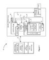
- Figure 1 is a block diagram of an example imaging system utilizing the imaging unit of the present disclosure.
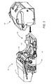
- Figure 2 is a view of the imaging unit with the handle mechanism and the toner cartridge of the system of Fig. 1 .
- Figure 3 is a view depicting a user holding the imaging unit of Fig. 2 using the handle mechanism.
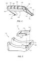
- Figures 4 is a perspective view of a handle member of the handle mechanism of Fig. 2 according to an example embodiment.
- Figure 5 is an exploded perspective view depicting the handle member and a frame portion of the imaging unit of Fig. 2 .
- Figure 6 is a perspective view illustrating the handle member of Fig. 4 in association with arm members of the handle mechanism according to an example embodiment.
- Figure 7A depicts an arm of the handle mechanism of Fig. 6 .
- Figure 7B depicts an arm of the handle mechanism of Fig. 6 engaged with a frame portion of the imaging unit of Fig. 2 .
- Figures 8A and 8B illustrate movement of the handle mechanism of Fig. 2 between collapsed and extended positions according to an example embodiment.
- Figures 9 and 10 are perspective views depicting the handle member of the imaging unit of Fig. 2 according to other example embodiments.
- image encompasses any printed or digital form of text, graphic, or combination thereof.
- output encompasses output from any printing device such as color and black-and-white copiers, color and black-and-white printers, and so-called “all-in-one devices” that incorporate multiple functions such as scanning, copying, and printing capabilities in one device.
- button means any component, whether a physical component or graphic user interface icon, that is engaged to initiate output.
- imaging system 20 may include an imaging apparatus 22 and a computer 24.
- Imaging apparatus 22 communicates with computer 24 via a communications link 26.
- communications link is used to generally refer to structure that facilitates electronic communication between multiple components, and may operate using wired or wireless technology and may include communications over the Internet.
- imaging apparatus 22 is shown as a multifunction machine that includes a controller 28, a print engine 30, a laser scan unit (LSU) 31, an imaging unit 32, a developer unit 34, a toner cartridge 35, a user interface 36, a media feed system 38 and media input tray 39 and a scanner system 40.
- Imaging apparatus 22 may communicate with computer 24 via a standard communication protocol, such as for example, universal serial bus (USB), Ethernet or IEEE 802.xx.
- a multifunction machine is also sometimes referred to in the art as an all-in-one (AIO) unit.
- imaging apparatus 22 may be, for example, an electrophotographic printer/copier including an integrated scanner system 40, or a standalone scanner system 40.
- Controller 28 includes a processor unit and associated memory 29, and may be formed as one or more Application Specific Integrated Circuits (ASIC).
- Memory 29 may be any volatile or non-volatile memory or combination thereof such as, for example, random access memory (RAM), read only memory (ROM), flash memory and/or non-volatile RAM (NVRAM).
- RAM random access memory
- ROM read only memory
- NVRAM non-volatile RAM
- memory 29 may be in the form of a separate electronic memory (e.g., RAM, ROM, and/or NVRAM), a hard drive, a CD or DVD drive, or any memory device convenient for use with controller 28.
- Controller 28 may be, for example, a combined printer and scanner controller.
- controller 28 communicates with print engine 30 via a communications link 50. Controller 28 communicates with imaging unit 32 and processing circuitry 44 thereon via a communications link 51. Controller 28 communicates with toner cartridge 35 and processing circuitry 45 therein via a communications link 52. Controller 28 communicates with media feed system 38 via a communications link 53. Controller 28 communicates with scanner system 40 via a communications link 54. User interface 36 is communicatively coupled to controller 28 via a communications link 55. Processing circuit 44, 45 may provide authentication functions, safety and operational interlocks, operating parameters and usage information related to imaging unit 32 and toner cartridge 35, respectively. Controller 28 serves to process print data and to operate print engine 30 during printing, as well as to operate scanner system 40 and process data obtained via scanner system 40.
- Computer 24 may be, for example, a personal computer, electronic tablet, smartphone or other hand-held electronics device, may include memory 60, such as volatile and/or non-volatile memory, an input device 62, such as a keyboard, and a display monitor 64.
- Computer 24 further includes a processor, input/output (I/O) interfaces, and may include at least one mass data storage device, such as a hard drive, a CD-ROM and/or a DVD unit (not shown).
- Computer 24 includes in its memory a software program including program instructions that function as an imaging driver 66, e.g., printer/scanner driver software, for imaging apparatus 22.
- Imaging driver 66 is in communication with controller 28 of imaging apparatus 22 via communications link 26.
- Imaging driver 66 facilitates communication between imaging apparatus 22 and computer 24.
- One aspect of imaging driver 66 may be, for example, to provide formatted print data to imaging apparatus 22, and more particularly, to print engine 30, to print an image.
- Another aspect of imaging driver 66 may be, for example, to facilitate collection of scanned data.
- imaging apparatus 22 it may be desirable to operate imaging apparatus 22 in a standalone mode.
- imaging apparatus 22 In the standalone mode, imaging apparatus 22 is capable of functioning without computer 24. Accordingly, all or a portion of imaging driver 66, or a similar driver, may be located in controller 28 of imaging apparatus 22 so as to accommodate printing and scanning functionality when operating in the standalone mode.
- Print engine 30 may include laser scan unit (LSU) 31, imaging unit 32, and a fuser 37, all mounted within imaging apparatus 22.
- the imaging unit 32 further includes a cleaner unit 33 housing a waste toner removal system and a photoconductive drum, developer unit 34 and a toner cartridge 35 that are removably mounted within imaging unit 32.
- the cleaner unit 33 and developer unit 34 are assembled together and installed into a frame 92 to form the imaging unit 32.
- the toner cartridge 35 is then installed over the frame in a mating relation with the developer unit 34.
- Laser scan unit 31 creates a latent image on the photoconductive drum in the cleaner unit 33.
- the developer unit 34 has a toner sump containing toner which is transferred to the latent image on the photoconductive drum to create a toned image.
- the toned image is subsequently transferred to a media sheet received in the imaging unit 32 from media input tray 39 for printing.
- Toner remnants are removed from the photoconductive drum by the waste toner removal system.
- the toner image is bonded to the media sheet in the fuser 37 and then sent to an output location or to one or more finishing options such as a duplexer, a stapler or hole punch.
- the toner cartridge 35 removably mates with the developer unit 34 in imaging unit 32.
- An exit port on the toner cartridge 35 communicates with an inlet port on the developer unit 34 allowing toner to be periodically transferred from the toner cartridge 35 to resupply the toner sump in the developer unit 34.
- Imaging unit 32 includes developer unit 34, a cleaner unit 33 and housing 90 which may contain the cleaner unit 33 and developer unit 34.
- Developer unit 34 and cleaner unit 33 are assembled together with frame portion 92, with toner cartridge 35 being slidably received over frame portion 92.
- the imaging unit 32 is initially slidably received in the imaging apparatus 22.
- the toner cartridge 35 is then inserted in imaging apparatus 22 over frame portion 92 and into operative engagement with developer unit 34. This arrangement allows the toner cartridge 35 to be removed and reinserted easily when replacing an empty toner cartridge without having to remove imaging unit 32.
- both the toner cartridge 35 and imaging unit 32 may be readily removed to allow access to the media jam.
- the developer unit 34, cleaning unit 33 and frame portion 92 may also be readily removed and reinserted when required, however, this would normally occur with less frequency than the removal and reinsertion of toner cartridge 35.
- Figure 2 also shows the imaging unit 32 with a handle mechanism 100 attached to a frame portion 92 of the housing 90 and adapted for relatively easily supporting of imaging unit 32.
- Handle mechanism 100 may include a handle member 110.
- the handle mechanism 100 is shown in Fig. 2 with handle member 110 in the collapsed position in which it is substantially flush with a surface of frame portion 92 when not in use.
- the toner cartridge 35 removably mates with the developer unit 34 of the imaging unit 32 by being positioned over handle member 110.
- Figure 3 is a view depicting a user holding the imaging unit 32 through use of the handle mechanism 100.
- a user may pull the handle member 110 to an extended position for lifting imaging unit 32.
- a pair of arms 210 is pivotably attached to handle member 110 and may limit the extent of rotational movement of the handle member 110 from the collapsed position, as explained in greater detail below.
- a majority of the effective weight of the imaging unit 32 may be towards the front thereof opposite the location of handle mechanism 100, and thus generates a downward force in the direction D1 as shown in Fig. 3 .
- the lower portion of the user's palm or wrist may engage or otherwise contact an end of frame portion 92, and a twisting force may be thereby provided in the direction D2 to counter the effective weight of the imaging unit 32.
- a twisting force may be thereby provided in the direction D2 to counter the effective weight of the imaging unit 32.
- a user may relatively steadily hold the imaging unit 32 during installation within imaging apparatus 22.
- Figure 4 is a perspective view depicting the handle member 110.
- the handle member 110 may include a gripping segment 112 for a user to grasp during lifting of the imaging unit 32.
- the gripping segment 112 may include lifting features 128 which are indentions defined along gripping segment 112 and sized to receive a user's finger to aid the user in initially lifting the handle member 110 from the collapsed position.
- the gripping segment 112 may also include spaced finger guides 130 to enable a user to better grip the gripping segment 112. Further, a bottom portion 132 of gripping segment 112 may be bowed ( Fig.
- the handle member 110 may also include a connecting segment for connecting gripping segment 112 to frame portion 92.
- the connecting segment includes two side segments 114 which extend from opposed ends of gripping segment 112.
- Each side segment includes a first coupling mechanism 116 disposed at its distal end.
- Each first coupling mechanism 116 may be substantially cylindrical and include a tab 118 extending substantially radially outwardly therefrom for pivotably engaging the handle member 110 to the frame portion 92, as discussed in greater detail below. It is understood that first coupling mechanism 116 may have different shapes for rotatably engaging with frame portion 92.
- the handle member 110 in the present example embodiment, may also include an aperture 124 with slot portion 126 defined at either end portion of gripping segment 112.
- Figure 5 is an exploded view of the handle member 110 with frame portion 92 of housing 90.
- Frame portion 92 may include opposed apertures 120 with corresponding slot portions 122 that are sized for receiving first coupling mechanisms 116 of side segments 114.
- the first coupling mechanism 116 of each side segment 114 engages with an aperture 120 having slot portion 122.
- handle member 110 is pivotable relative to frame portion 92 about an axis defined by apertures 120.
- First tab 118 of each first coupling mechanism 116 prevents disconnection of side segment 114 from frame portion 92 because once first coupling mechanism 116 of side segment 114 is inserted into aperture 120 of frame portion 92 and placed in an operational position therewith, slot 122 no longer lines up with first tab 118.
- frame portion 92 includes the first coupling mechanisms 116 extending towards each other, and each side segment 114 includes at its distal end an aperture 120 with slot portion 122 for engagement with first coupling mechanisms 116.
- arms 210 are pivotably attached to handle member 110.
- Fig. 6 shows in more detail arms 210 coupled to handle member 110
- Fig. 7A illustrates details of arm 210.
- Arm 210 may include a second coupling mechanism 212 disposed on a first end 214 of arm 210.
- Second coupling mechanism 212 may include a radially extending second tab 220. Similar in structure to the first coupling mechanism 116, each second coupling mechanism 212 is operably received in an aperture 124 of gripping segment 112. Once inserted into apertures 124, second coupling mechanisms 116 allow arms 210 to pivotably rotate about gripping segment 112, and particularly about an axis defined by apertures 124 thereof.
- Second tab 220 prevents disconnection of arm 210 from the handle member 110 because once second coupling mechanism 212 is inserted into aperture 124 of gripping element 112 and placed in an operational position with respect to handle member 110, slot 126 of aperture 124 no longer lines up with second tab 220.
- Arm 210 may further include a third coupling mechanism 216 disposed on an opposed second end thereof.
- Third coupling mechanism 216 slidingly engages with frame portion 92 and may include a rounded portion.
- third coupling mechanism 216 has a substantially cylindrical shape, but it is understood that third coupling mechanism 216 may have other shapes.
- Third coupling mechanism 216 sliding engages with tracks 104 that are disposed in substantially parallel relation along frame portion 92.
- Figure 7B depicts arm 210 engaged with track 104.
- FIGs 8A and 8B depict the handle mechanism 100 in the collapsed and extended positions, respectively.
- each arm 210 is pivotably attached to handle member 110 and is sliding engaged with its corresponding track 104.
- arms 210 are substantially parallel with side segments 114 of handle member 110, along a bottom portion of frame 92.
- side segments 114 pivot about frame portion 92.
- arms 210 slide along tracks 104 in direction D3 ( Fig. 8B ).
- Each arm 210 also pivots frame portion 92 when sliding along corresponding track 104.
- each third coupling mechanism 216 of the arm 210 is disposed along an end portion of corresponding track 104.
- Each track 104 limits the extent of sliding movement of its corresponding arm 210 and as a result limits the rotational movement of the handle member 110.
- a first angle ⁇ 1 may be defined between the side segment 114 of handle member 110 and a horizontal line traversing the pivot point of the handle member 110 substantially parallel to the orientation of the frame portion 92 of the housing 90.
- a second angle ⁇ 2 may be defined between each arm 210 and the handle member 110.
- the first angle ⁇ 1 When handle member 110 is in the extended position, the first angle ⁇ 1 may be between about 25 degrees and about 35 degrees while the second angle ⁇ 2 may be greater than 90 degrees.
- the first angle ⁇ 1 and the second angle ⁇ 2 are set to enable the handle member 110 to automatically return to the collapsed position by gravity when released from a user's grip.
- Figure 9 depicts another example embodiment of the handle member 110.
- the, gripping segment 112 extends substantially between a majority of the two side segments 114a towards the first coupling mechanism 116. This extension of gripping segment 112 prevents a user's thumb from being uncomfortably slid underneath the gripping segment 112 when grasped by a user.
Landscapes
- Physics & Mathematics (AREA)
- General Physics & Mathematics (AREA)
- Electrophotography Configuration And Component (AREA)
- Dry Development In Electrophotography (AREA)
Applications Claiming Priority (2)
| Application Number | Priority Date | Filing Date | Title |
|---|---|---|---|
| US201161581872P | 2011-12-30 | 2011-12-30 | |
| US13/400,225 US8718511B2 (en) | 2011-12-30 | 2012-02-20 | Imaging unit having a pivoting, collapsible handle |
Publications (2)
| Publication Number | Publication Date |
|---|---|
| EP2610690A2 true EP2610690A2 (de) | 2013-07-03 |
| EP2610690A3 EP2610690A3 (de) | 2016-05-25 |
Family
ID=47428475
Family Applications (1)
| Application Number | Title | Priority Date | Filing Date |
|---|---|---|---|
| EP12191651.4A Withdrawn EP2610690A3 (de) | 2011-12-30 | 2012-11-07 | Bildgebungseinheit mit zusammenklappbarem Handgriff |
Country Status (3)
| Country | Link |
|---|---|
| US (1) | US8718511B2 (de) |
| EP (1) | EP2610690A3 (de) |
| CN (1) | CN103186062B (de) |
Families Citing this family (1)
| Publication number | Priority date | Publication date | Assignee | Title |
|---|---|---|---|---|
| US12055872B2 (en) | 2022-09-15 | 2024-08-06 | Lexmark International, Inc. | Toner container handle |
Family Cites Families (25)
| Publication number | Priority date | Publication date | Assignee | Title |
|---|---|---|---|---|
| JPS59198476A (ja) * | 1983-04-26 | 1984-11-10 | Canon Inc | 現像装置 |
| JPS62209571A (ja) * | 1986-03-11 | 1987-09-14 | Konishiroku Photo Ind Co Ltd | 現像器ユニツト |
| US4839691A (en) * | 1986-03-31 | 1989-06-13 | Kabushiki Kaisha Toshiba | Image forming apparatus |
| JPH03180861A (ja) * | 1989-12-08 | 1991-08-06 | Matsushita Electric Ind Co Ltd | 画像記録装置 |
| DE4139428C2 (de) * | 1990-11-30 | 1994-07-07 | Ricoh Kk | Elektrophotographisches Gerät |
| JPH08220819A (ja) * | 1995-02-16 | 1996-08-30 | Ricoh Co Ltd | 画像形成装置 |
| KR0175588B1 (ko) * | 1996-01-25 | 1999-04-01 | 김광호 | 개폐식 탑커버를 가지는 전자사진 현상방식을 이용한 화상형성장치의 현상기 |
| JP2003202792A (ja) * | 2002-01-07 | 2003-07-18 | Oki Data Corp | プロセスカートリッジ及び画像形成装置 |
| EP1898274B1 (de) * | 2002-09-24 | 2011-04-20 | Ricoh Company, Ltd. | Bilderzeugungsvorrichtung mit einem Bildträgerelement und einem Schutzverschluss |
| KR100544191B1 (ko) * | 2003-07-05 | 2006-01-23 | 삼성전자주식회사 | 감광유닛 및 전사유닛 교환 시스템 및 그 교환 시스템을가진 인쇄기 |
| KR100528880B1 (ko) * | 2003-10-16 | 2005-11-16 | 삼성전자주식회사 | 감광유닛 |
| USD552671S1 (en) * | 2004-08-05 | 2007-10-09 | Konica Minolta Business Technologies, Inc. | Portion of a toner container |
| KR100605166B1 (ko) * | 2004-08-28 | 2006-07-28 | 삼성전자주식회사 | 접철식 손잡이를 가지는 현상유닛 및 이를 구비한화상형성장치 |
| KR20080026978A (ko) * | 2006-09-22 | 2008-03-26 | 삼성전자주식회사 | 화상형성장치 |
| JP2008090121A (ja) * | 2006-10-04 | 2008-04-17 | Fuji Xerox Co Ltd | カートリッジ及び画像形成装置 |
| KR100950492B1 (ko) * | 2007-03-15 | 2010-03-31 | 삼성전자주식회사 | 현상기, 이를 구비한 화상형성장치, 및 현상기의 탈착방법 |
| JP4591569B2 (ja) * | 2008-07-22 | 2010-12-01 | ブラザー工業株式会社 | 画像形成装置 |
| CN101373369B (zh) * | 2008-08-22 | 2015-02-25 | 珠海赛纳打印科技股份有限公司 | 一种成像处理盒 |
| US8295742B2 (en) * | 2008-11-10 | 2012-10-23 | Ricoh Company, Limited | Powder container, powder supplying device, and image forming apparatus |
| US8634743B2 (en) * | 2009-03-27 | 2014-01-21 | Fuji Xerox Co., Ltd. | Detachable body and image forming apparatus |
| JP4821884B2 (ja) * | 2009-05-29 | 2011-11-24 | ブラザー工業株式会社 | 画像形成装置の構成ユニットおよび現像ユニット |
| JP2011033924A (ja) * | 2009-08-04 | 2011-02-17 | Canon Inc | カートリッジ及び電子写真画像形成装置 |
| US8849155B2 (en) * | 2010-07-23 | 2014-09-30 | Brother Kogyo Kabushiki Kaisha | Image forming device |
| JP5552943B2 (ja) * | 2010-07-29 | 2014-07-16 | 株式会社リコー | 定着装置及び画像形成装置 |
| JP2012155266A (ja) * | 2011-01-28 | 2012-08-16 | Brother Ind Ltd | 画像形成装置 |
-
2012
- 2012-02-20 US US13/400,225 patent/US8718511B2/en active Active
- 2012-11-07 EP EP12191651.4A patent/EP2610690A3/de not_active Withdrawn
- 2012-12-10 CN CN201210528242.9A patent/CN103186062B/zh not_active Expired - Fee Related
Non-Patent Citations (1)
| Title |
|---|
| None |
Also Published As
| Publication number | Publication date |
|---|---|
| US8718511B2 (en) | 2014-05-06 |
| EP2610690A3 (de) | 2016-05-25 |
| CN103186062B (zh) | 2016-01-20 |
| US20130170854A1 (en) | 2013-07-04 |
| CN103186062A (zh) | 2013-07-03 |
Similar Documents
| Publication | Publication Date | Title |
|---|---|---|
| EP4063970B1 (de) | Elektrische kontakte für tonerpatrone | |
| JP4995311B2 (ja) | 電子写真画像形成装置 | |
| US11520282B2 (en) | Replaceable units of an electrophotographic image forming device having a shipping or storage separator | |
| JP4871652B2 (ja) | 画像形成装置 | |
| JP5481502B2 (ja) | 画像形成装置及び現像器 | |
| JP2009116182A (ja) | 画像形成装置 | |
| US8543034B2 (en) | Electrophotographic color image forming apparatus and cartridge | |
| US8718511B2 (en) | Imaging unit having a pivoting, collapsible handle | |
| US11061360B2 (en) | Image forming apparatus | |
| JP6586933B2 (ja) | 給紙装置及び画像形成装置 | |
| CN116184788B (zh) | 显影剂收纳装置以及图像形成装置 | |
| HK1186528A (en) | Imaging unit having a collapsible handle | |
| JP2018072562A (ja) | 電子機器 | |
| JP2008292545A (ja) | 画像形成装置 | |
| US20060087072A1 (en) | Paper cassette and image forming apparatus including the same | |
| JP2019139187A (ja) | 画像形成装置および消耗品収容用のトレイ | |
| JP2010002710A (ja) | 画像形成装置 | |
| US20090214255A1 (en) | Imaging cartridge and image forming apparatus | |
| JP6390561B2 (ja) | 画像形成装置 | |
| US20250142008A1 (en) | Image forming apparatus | |
| JP5533392B2 (ja) | 印刷装置 | |
| JP5891281B2 (ja) | 画像形成装置 | |
| JP6184367B2 (ja) | 画像形成装置 | |
| JP6204257B2 (ja) | 画像形成装置 | |
| JP2025042933A (ja) | 排出ユニット及び画像形成装置 |
Legal Events
| Date | Code | Title | Description |
|---|---|---|---|
| PUAI | Public reference made under article 153(3) epc to a published international application that has entered the european phase |
Free format text: ORIGINAL CODE: 0009012 |
|
| 17P | Request for examination filed |
Effective date: 20121107 |
|
| AK | Designated contracting states |
Kind code of ref document: A2 Designated state(s): AL AT BE BG CH CY CZ DE DK EE ES FI FR GB GR HR HU IE IS IT LI LT LU LV MC MK MT NL NO PL PT RO RS SE SI SK SM TR |
|
| AX | Request for extension of the european patent |
Extension state: BA ME |
|
| RIN1 | Information on inventor provided before grant (corrected) |
Inventor name: LACTUAN, KATRINA Inventor name: HALE, JASON PAUL Inventor name: ROGERS, MATTHEW LEE Inventor name: SEAMAN, KEITH |
|
| REG | Reference to a national code |
Ref country code: HK Ref legal event code: DE Ref document number: 1186528 Country of ref document: HK |
|
| PUAL | Search report despatched |
Free format text: ORIGINAL CODE: 0009013 |
|
| AK | Designated contracting states |
Kind code of ref document: A3 Designated state(s): AL AT BE BG CH CY CZ DE DK EE ES FI FR GB GR HR HU IE IS IT LI LT LU LV MC MK MT NL NO PL PT RO RS SE SI SK SM TR |
|
| AX | Request for extension of the european patent |
Extension state: BA ME |
|
| RIC1 | Information provided on ipc code assigned before grant |
Ipc: G03G 21/16 20060101AFI20160420BHEP |
|
| STAA | Information on the status of an ep patent application or granted ep patent |
Free format text: STATUS: REQUEST FOR EXAMINATION WAS MADE |
|
| STAA | Information on the status of an ep patent application or granted ep patent |
Free format text: STATUS: THE APPLICATION IS DEEMED TO BE WITHDRAWN |
|
| 18D | Application deemed to be withdrawn |
Effective date: 20161126 |
|
| REG | Reference to a national code |
Ref country code: HK Ref legal event code: WD Ref document number: 1186528 Country of ref document: HK |