EP2608941B1 - Form zur herstellung von betonformsteinen - Google Patents
Form zur herstellung von betonformsteinen Download PDFInfo
- Publication number
- EP2608941B1 EP2608941B1 EP11743531.3A EP11743531A EP2608941B1 EP 2608941 B1 EP2608941 B1 EP 2608941B1 EP 11743531 A EP11743531 A EP 11743531A EP 2608941 B1 EP2608941 B1 EP 2608941B1
- Authority
- EP
- European Patent Office
- Prior art keywords
- core
- core holder
- mould
- plates
- holder strip
- Prior art date
- Legal status (The legal status is an assumption and is not a legal conclusion. Google has not performed a legal analysis and makes no representation as to the accuracy of the status listed.)
- Active
Links
Images

Classifications
-
- B—PERFORMING OPERATIONS; TRANSPORTING
- B28—WORKING CEMENT, CLAY, OR STONE
- B28B—SHAPING CLAY OR OTHER CERAMIC COMPOSITIONS; SHAPING SLAG; SHAPING MIXTURES CONTAINING CEMENTITIOUS MATERIAL, e.g. PLASTER
- B28B7/00—Moulds; Cores; Mandrels
- B28B7/16—Moulds for making shaped articles with cavities or holes open to the surface, e.g. with blind holes
- B28B7/18—Moulds for making shaped articles with cavities or holes open to the surface, e.g. with blind holes the holes passing completely through the article
- B28B7/183—Moulds for making shaped articles with cavities or holes open to the surface, e.g. with blind holes the holes passing completely through the article for building blocks or similar block-shaped objects
-
- B—PERFORMING OPERATIONS; TRANSPORTING
- B28—WORKING CEMENT, CLAY, OR STONE
- B28B—SHAPING CLAY OR OTHER CERAMIC COMPOSITIONS; SHAPING SLAG; SHAPING MIXTURES CONTAINING CEMENTITIOUS MATERIAL, e.g. PLASTER
- B28B7/00—Moulds; Cores; Mandrels
- B28B7/0002—Auxiliary parts or elements of the mould
- B28B7/0014—Fastening means for mould parts, e.g. for attaching mould walls on mould tables; Mould clamps
-
- B—PERFORMING OPERATIONS; TRANSPORTING
- B28—WORKING CEMENT, CLAY, OR STONE
- B28B—SHAPING CLAY OR OTHER CERAMIC COMPOSITIONS; SHAPING SLAG; SHAPING MIXTURES CONTAINING CEMENTITIOUS MATERIAL, e.g. PLASTER
- B28B7/00—Moulds; Cores; Mandrels
- B28B7/16—Moulds for making shaped articles with cavities or holes open to the surface, e.g. with blind holes
- B28B7/162—Moulds for making shaped articles with cavities or holes open to the surface, e.g. with blind holes for building blocks or similar block-shaped articles
Definitions
- the invention relates to a mold for the mechanical production of concrete blocks, in which at least one mold core is arranged in at least one mold cavity.
- mandrels are arranged in the mold cavities.
- the mandrels are held on core holder strips, which horizontally span the mold cavities, in positions spaced from the side walls of the mold cavities.
- the mandrels are typically designed as sheet metal hollow body.
- the mandrels are commonly welded to the core holder strips, such. B. from the DE102004005045A1 known, but often leads to fractures of the core holder strips, in particular during the shaking phases of the production cycles, and then necessitates the replacement of the core holder strip, including all mandrels welded thereto.
- the present invention has for its object to provide a mold for the production of concrete blocks, which contains an advantageous mold core assembly with detachable connection between the mold core and core holder strip.
- the connecting elements are preferably designed as screw elements with a thread, which have at least one, preferably two opposite in the axial direction ends a tool approach. Screw elements here are understood both screws with external thread as well as elements with internal thread on the type of nuts, wherein preferably a connecting element consists in each case of the combination of a screw with a nut.
- the connecting elements are by the at least one side of the core holder strip on the side facing away from the holding plate cavity in holding plates and core holder strip and removable from these and accessible for tools for insertion or removal, said at least one cavity up by a detachable a base body of the mold core fastened lid assembly can be covered.
- a detachable a base body of the mold core fastened lid assembly can be covered.
- ends of the connecting elements can be reached with tools.
- exactly two fasteners are provided, which in the longitudinal direction of Kernhalterance are spaced apart and offset from the outer sides of the mold core in the direction of its center.
- a shape of the recess in the concrete block defining part of the mold core is called, which forms the concrete surface in the mold cavity assigning outer surface.
- a body also includes an upper portion having vertically extending outer surfaces on which pressure plates are moved downwardly during the solidification process, whereas the lower portion of the body defining the shape of the cavity in the concrete block typically tapers slightly conically downwardly to close it Dissolve the solidified concrete block from the mandrel to favor.
- the base body and cover assembly with fasteners then form the mandrel.
- the lateral outer surface of the base body which comes into contact with the amount of concrete in the mold cavity can in particular also be continuously closed continuously in extension of the connecting elements in their axial directions, which are typically in the region of said upper section.
- the tool access to the connecting elements takes place in the lid assembly dissolved by the main body through the upper opening of the cavity, wherein the tool application is particularly simple due to the small vertical distance of the connecting elements from the upper cavity opening, which may also have a large cross-section.
- the top of the lid assembly is no higher than the top edge of the core holder bar and typically in a plane with that top edge of the core holder bar.
- the holding plates are advantageously welded to the base body and preferably proceed uninterruptedly in the longitudinal direction of the core holder strip between opposite side walls of the base body.
- a welding of the vertical end edges of the holding plates at their longitudinally opposite ends with the side walls of the body seals advantageously at these locations, the cavity against the penetration of constituents of the concrete amount.
- the lid arrangement can have a lid which extends over the then advantageously lowered upper edge of the core holder strip.
- two separate covers are provided in the cover assembly, each covering one of the cavities and are each separately detachably fastened to the base body.
- the attachment of a lid to the base body is advantageously carried out by means of at least one screw which engages over the lid surface lying over the cavity and engages in a mating thread within the base body.
- the mating thread is formed on a counter-plate, which is vertically spaced from the lid and is preferably lower than the connecting elements.
- the counter-plate is in the region of the lower edge of the core holder strip, in particular by a small amount offset against this down.
- the counter-plate can limit the cavity downwards.
- the fastening screws are advantageously sunk into the lid surface.
- the fastening screws preferably extend substantially vertically.
- Between the cover and counter plate at least one spacer element is inserted, which adjusts a defined vertical distance between the cover and the counter plate and the lid is supported vertically against the counter plate.
- a plurality of such spacers are present, which can be designed in particular as the fastening screws surrounding spacers.
- the lid may also be vertically supported on the upper edge of the holding plate and / or on the upper edges of the side walls of the base body.
- the lid is supported horizontally with its edge facing away from the core holder strip on the inside of the upper edge of the base body.
- a mold cavity can be spanned by more than one core holder bar, wherein the plurality of core holder bars then preferably run parallel in a manner known per se.
- Molded cores can, in particular for large-volume concrete blocks, be held on two or more core holder strips, in which case the individual core holder strips are each assigned their own holding plates and the core holder strips are connected via separate screw connections with the associated holding plates.
- the direction and position information top, bottom, horizontal, vertical and the like can be seen as related to the regular operating position of the mold, in which it is placed with its lower boundary plane on a horizontal support.
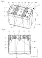
- Fig. 1 shows in view obliquely from above a held on a core holder strip KL mold core FK.
- the shape and the mold cavity are not shown for clarity.
- the main body can advantageously be constructed in the usual way by two half-shells which abut one another along a joint TF and are preferably welded together.
- the joint TF lies in a yz-plane of a co-marked xyz-coordinate system whose coordinates x and y are horizontal in the regular operating position of the mold, so that the z-direction indicates the vertical direction.
- the gap TF between two half-shells can also run differently within the main body of the mandrel.
- the main body of the mandrel forms a hollow sheet metal core, which preferably consists of two half-shells.
- the two half-shells are advantageously each made of a one-piece planar sheet metal blank by bending individual sheet metal sections relative to each other or by deep drawing a sheet produced.
- the lower portion KU of the main body essentially determines the recess in the concrete block to be produced and in the example shown is typically slightly tapered down over most of its vertical extension and formed tapering towards its center in its lower region.
- the upper portion KO of the main body forms with its outer surface a cylindrical lateral surface with a vertical cylinder axis. During the solidification of filled into a mold cavity to the top of the mold core amount of concrete pressure plates move along this upper portion KO vertically downwards.
- the sheet-metal hollow body formed by the main body of the mold core FK is closed at the top by two cover plates D1, D2, which are fastened in a manner to be described by means of fastening screws to components of the base body.
- the cover plates D1, D2 run with a narrow gap, which can also be sealed by additional sealing means, along the upper edge OG of the upper portion KO of the main body.
- the cover plates D1, D2 are as parts of a cover assembly in their in Fig. 1 stabilized position for which possibilities are given.
- Screw heads SK of the fastening screws are designed in a countersunk head shape and lie substantially flush in an xy plane with the upper surfaces of the cover plates D1, D2.
- the core holder strip KL is passed through lateral recesses KA in the upper portion KO of the main body of the mandrel.
- the upper edge OL of the core holder strip preferably lies in the x-y plane of the upper sides of the cover plates D1, D2, but in special cases may also protrude beyond this.
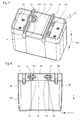
- Fig. 2 is a view obliquely from above on the arrangement Fig. 1 shown, but with the cover plates D1, D2 are removed and the view is free in two cavities H1, H2 on opposite sides of the core holder strip KL.
- Fig. 2 discernible are two holding plates HP1, HP2, which are arranged on opposite sides of the core holder strip KL and abut against the side surfaces of the core holder strip KL or are spaced therefrom by a narrow gap.
- the holding plates HP1, HP2 are components of the mold core and are connected to the core holder bar via connecting elements, which are preferably designed as sketched as screw elements. The screw axes of the screw elements extend in the y direction.
- the screw elements pass through openings aligned in the y-direction in the holding plates HP1, HP2 and in the core holder strip KL, whereby the screw elements themselves or via additional sleeves engage in said aligned openings largely free of play.
- the screw elements may in particular have a shank with a screw head and a screw thread facing away from the screw head and a screw nut HM.
- Screw heads and nuts each have tool approaches, for example Hexagonal contours as opposed ends of the fasteners.
- the ends of the fasteners with the tool approaches protrude into the side of the core holder strip present cavities H1, H2 and are in the in Fig. 2 illustrated state of the mold core assembly with removed cover plates easily accessible from above and in this case for connection of the main body of the mold core with the core holder strip KL used or removable to release the body of the core holder strip.
- the cavities H1, H2 are limited in the preferred example outlined in the vertical downward direction by counter-plates GP1, GP2, which substantially fill the entire inner cross-section of the body laterally of the core holder bar.
- the counter-plates need not be fitted over their entire outer edges in the cavity and can also be supported only selectively at a plurality of positions on the wall inner sides of the side walls of the core and connected thereto.
- the counter plates GP1, GP2 contain counter threads GG, these counter threads GG are preferably formed in nuts, which are inserted into bores of the counter plates GP1, GP2 from below and held securely there, for example, can be welded.
- the mating thread can also be performed directly as threaded holes in the counter plates with sufficient thickness of the counter plates.
- the holding plate HP1 is integrally connected to the counter plate GP1 in the form of a sheet metal angle and in particular produced from a flat sheet metal blank by folding.
- the opposite in the x-direction vertical end edges of the holding plate HP1 are advantageously welded to the side walls of the upper portion KO of the main body.
- the counter plate GP1 is welded along its edges to the base body, wherein the vertical Position of the counter-plate GP1 is advantageously located approximately in the region of the lower edge of the core holder bar UK.
- Holding plate HP2 and counter plate GP2 are executed in a similar manner as a uniform angled sheet metal body and welded to the body.
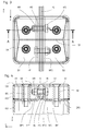
- Fig. 3 shows the arrangement after Fig. 1 in plan view of the cover plates D1, D2, ie, viewed in the direction opposite to the z-direction.
- Hidden parts of the mold core arrangement are indicated by broken lines, in particular the holding plates HP1, HP2 and the screw elements with screws HS, screw head WS and screw nut HM.
- Fig. 4 shows a sectional view taken along the stepped section line AA of Fig. 3 , It can be seen from the sectional view that the core holder strip KL is chamfered by chamfers both at its upper edge OL and at its lower edge UL with respect to a rectangular cross section.
- Such a cross-sectional shape of core holder strips is known per se.
- the holding plates HP1, HP2 fit closely against the side surfaces of the core holder strip and, like the core holder strip, are penetrated by screws HS as connecting elements.
- screws HS By screwing the positions of retaining plates and core holder strip are fixed in all directions, but by at least limited rotation of Kernhaltermann and / or holding plates relative to the axes of the connecting elements still a dynamic vertical deflection of the core holder strip, especially in shaking operation is possible.
- the holding plates are advantageously clamped by means of screws HS against the side surfaces of the core holder strip and thereby also frictionally connected thereto. At the same time, tilting of the mold core is reliably blocked by the two connecting elements spaced apart in the x-direction.
- the nuts HM and the screw heads WS of the screw elements as connecting elements lie in cavities H1, H2, which are present on both sides of the core holder strip and which are closed at the top by the cover plates D1 and D2. Downwards, the cavities H1, H2 are limited by the counter plates GP1, GP2, on which nuts BM are arranged with counter threads to fastening screws BS. Laterally outward, the cavities H1, H2 are closed by the side walls of the upper portion KO of the main body of the mold core.
- the screw heads SK of the mounting screws BS are executed in countersunk-head shape and sunk into conical recesses of the cover plates D1, D2, so that there are no over the tops of the cover plates protruding components.
- the cover plates D1, D2 are in the example sketched outlined with their Kernhalterance KL assigning edges on side surfaces of the core holder strip and are fitted in the formed by the top edge OG of the upper portion KO contour of the upper openings of the cavities so that in the y-direction of Kernhalterance KL remote from edges of the cover plates and the opposite direction in the x-direction edges of the cover plates closely against the inner sides of the side walls of the upper and / or lower portion KO, KU and the cover plates D1, D2 therefore in cooperation with the concerns on side surfaces of the core holder strip KL are held horizontally in a defined position.
- the cover plates D1, D2 lie with their edges facing the core holder strip KL on the upper edge of the holding plates HP1, HP2 and are additionally spaced in the y-direction from the holding plates HP1, HP2, by spacer elements in the form of spacers HU, which Surround the screws BS, vertically supported against the counter-plates GP1, GP2 and held so in the vertical direction in a defined position. Number and arrangement of the mounting screws BS may vary in individual cases.
- the cover plates D1, D2 can also have along their outline edges a milled step with which they rest against upper edges of holding plates and / or side walls of the upper portion KO of the main body of the mandrel and so a vertical and / or horizontal fixation of the cover plates is achieved.
- At joints between individual plates and / or walls of the mold core sealing means may be inserted to prevent the penetration of components of the concrete amount in cavities of the mold core.
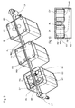
- Fig. 5 is in oblique view from above analogous to the illustration Fig. 2 a mold core KD shown, which is held on two parallel core holder strips LL and LR.
- the core holder strips LL, LR are preferably parallel and are spaced apart from each other in the y-direction and guided through separate recesses KA of the side walls of the mold core.
- holding plates HPL and HPR which are welded to the inner surfaces of the side walls of the mold core KD and analogously to the preceding example, are arranged and to which the core holder strips are held by means of holding screws HS.
- the holding plates HPL and HPR form each with counter plates GL and GR one-piece angled plates.
- the counterplates GL, GR are welded to the mold core KD point by point or circumferentially on their edges facing the inner walls of the mold core KD and, in the manner already described, have mating threads GG for receiving fastening screws.
- a holding plate HML On the core holder strip LR side facing the Kernhalterance LL is a holding plate HML and in a corresponding manner on the Kernhalterance LL side facing the Kernhalteror LR arranged a holding plate HMR, which preferably also with the inner walls of the core KD are welded.
- a counter plate GM Between the holding plates HML and HMR and offset from the upper edge of the core holder strips downwardly runs a counter plate GM, which is designed in the illustrated preferred embodiment in one piece with the holding plates HML and HMR and forms an upwardly open U-shape.
- the counter plate GM in turn has mating thread.
- Holding plates HML, HMR and counter plate GM are advantageously produced by folding a flat sheet metal blank.
- openings are formed in the core holder strips and the holding plates through which holding screws HS are passed.
- the tool projections WS of the retaining screws and the associated retaining nuts HM are in the in Fig. 5 illustrated state of the mold core, in which the cavities above the counter plates GL, GM and GR are not covered, easily accessible.
- the screwing takes place in an analogous manner to the example described in detail above.
- Fig. 6 shows a section in a yz plane through the mandrel KD, where in the illustration Fig. 6 analogous to the representation of Fig. 4 Cover plates are mounted over said cavities.
- the lower edge of the core holder has a stepped course, which is due to the fact that the retaining screws HS and the counter threads GS are not in common yz planes and the cutting surface for the Fig. 6 stepped in the x-direction is chosen and thus the cuts in the lower inclined boundary surfaces of the mandrel appear at different heights.
- Fig. 6 it can be seen that the cavities above the counter plates GL, GM and GR are each covered by their own cover plates DL, DM and DR.
- the cover plates are in turn attached to already described manner by means of fastening screws BS on the mandrel and through Spacers HU held in a defined vertical distance from the counter plates.
- nuts BM are again welded, which form the counter-threads to the fastening screws BS.
- Fig. 7 shows a modification to the embodiment according to Fig. 5 in that in this example between the two spaced core holder strips LL, LR instead of the holding plates HML, HMR and the counter plate GM, a center cover is provided which has a cover plate GD and from this down-angled side plates SL and SR and a downwardly open U Form forms.
- the side plates SL, SR have aligned openings to the openings in the core holder strip and carry at their core holder strips facing away from inner surfaces welded nuts SM.
- An attachment of the core holder strips on the holding plates is carried out by screwing retaining screws HS in the welded to the inner surfaces of the side plates SL nuts SM.
- Fig. 7 the center lid and the core holder strip are shown partially cut out, whereby the view is released in the mounted on the center lid the user not accessible side of the side panel SL.
- the screw connection between the core holder strips LL, LR and mandrel KD is still solvable, since the tool approaches WS of the retaining screws HS in the cavities on the cover plates GL, GR are still accessible.
- the center cover GD is preferably not welded in this embodiment with the mandrel KD.
- Fig. 9 shows a mold core assembly with three cores on a continuous between two strip holders LH Kernhalterance KL.
- the strip holder LH are outside of the stone field of the form in a conventional manner arranged and brace the core holder strip on the outer Formnestcharactern against existing wall recesses down.
- the attachment of the cores to the core holder strip succeeds as in the examples Fig. 1 to Fig. 4 by means of holding plates HP of the core and guided through aligned holes in the core holder bar and clamped by nuts HM retaining screws HS.
- counterplates GM are provided within the core. The components mentioned are in the illustrated without the cover assembly left of the three cores of Fig. 9 recognizable.
- cover plates DM successes in this example of the left of the three cores by means of a magnet assembly with two permanent magnets MA, which are arranged below the cover plates DM and hold the cover plates DM, which consist of soft magnetic material, via magnetic forces on the main body of the core.
- the permanent magnets MA can be fastened to the side walls of the upper part KO of the main body of the mold core.
- the permanent magnets MA but as outlined on any existing counter-plates GM of the main body of the core attached.
- the permanent magnets MA can be screwed to the counter plates GM or the cover plates, but are preferably held solely by magnetic forces on the soft magnetically shaped counter plates GM and cover plates and are advantageously fixed by additional means against horizontal displacements in the planes of the counter plates.
- the fixation can be done by additional templates between counter plates and cover plates.
- a horizontal fixation by forming depressions in counter-plates or cover plates.
- the permanent magnet arrangements advantageously contain on each side of the core holder strip at least two spaced-apart magnets, which can have opposite polar orientations N or S, so that the cover plates DM and the counterplates GM each form magnetic bridges of an entire closed magnetic circuit.
- a magnet assembly with two magnets MAje cover plate is shown in the left core shown without cover plates.
- positions of four magnets MQ1 to MQ4 are shown under the cover plates DM with continuous lines.
- the four magnets are advantageously arranged in the corner regions of the cover plates.
- pairs of diagonally opposite magnets MQ1, MQ3 and MQ2, MQ4 have equal pole alignments and the two pairs have opposite polar orientations, which is illustrated by pole designations N and S.
- the cover plates DM can advantageously be fixed in a form-fitting manner similar to the manner already described for the preceding embodiments.
- To intercept tilting moments can be arranged in the region of the outer corners of the core cross-section advantageously when using at least three magnets per cover plate two magnets, as shown by the broken lines for the covered by the cover plates magnetic poles in the middle and right of three cores is indicated.
- the respective cover plate is advantageously supported perpendicular to the plate surface alone on the magnets MQ1 to MQ4 and is not on the top of the associated holding plate HP. This ensures a high magnetic holding force and a reliable mechanical support even at low height tolerances of the magnets possible.
- magnets with linear oppositely arranged and aligned magnetic poles and the counter plates as magnetic inferences and magnet arrangements can be provided with U-shaped bent magnets, which are fixed to the counter plates or the lids and magnetically held on the other part.
- Fig. 10 shows an upper portion of a preferred embodiment of a core with four magnets in the arrangement as in the middle core of Fig. 9 in side view cut behind the side wall.
- the thereby visible magnets MQ1, MQ4 are against by z.
- a fixation against displacements is also possible by other mechanical means.
- the cover plates are secured against lateral horizontal displacements by low-clearance fit between the inner walls of the core upper part and the core holder strip.
- the tops of the cover plates do not protrude or only slightly beyond the upper edges of the walls of the core upper part KO.
- the tops of the cover plates can be lowered in an advantageous embodiment by a small amount against the upper edges of the inner walls of the upper core part.
Landscapes
- Engineering & Computer Science (AREA)
- Manufacturing & Machinery (AREA)
- Chemical & Material Sciences (AREA)
- Ceramic Engineering (AREA)
- Mechanical Engineering (AREA)
- Moulds, Cores, Or Mandrels (AREA)
- Artificial Fish Reefs (AREA)
Priority Applications (2)
| Application Number | Priority Date | Filing Date | Title |
|---|---|---|---|
| PL11743531T PL2608941T3 (pl) | 2010-08-24 | 2011-08-11 | Forma do wytwarzania kształtówek betonowych |
| HRP20141179AT HRP20141179T1 (hr) | 2010-08-24 | 2011-08-11 | Kalup za proizvodnju lijevanih betonskih opeka |
Applications Claiming Priority (2)
| Application Number | Priority Date | Filing Date | Title |
|---|---|---|---|
| DE102010037142A DE102010037142A1 (de) | 2010-08-24 | 2010-08-24 | Form zur Herstellung von Betonformsteinen |
| PCT/EP2011/063824 WO2012025392A1 (de) | 2010-08-24 | 2011-08-11 | Form zur herstellung von betonformsteinen |
Publications (2)
| Publication Number | Publication Date |
|---|---|
| EP2608941A1 EP2608941A1 (de) | 2013-07-03 |
| EP2608941B1 true EP2608941B1 (de) | 2014-10-08 |
Family
ID=44630258
Family Applications (1)
| Application Number | Title | Priority Date | Filing Date |
|---|---|---|---|
| EP11743531.3A Active EP2608941B1 (de) | 2010-08-24 | 2011-08-11 | Form zur herstellung von betonformsteinen |
Country Status (7)
| Country | Link |
|---|---|
| EP (1) | EP2608941B1 (pl) |
| DE (1) | DE102010037142A1 (pl) |
| DK (1) | DK2608941T3 (pl) |
| ES (1) | ES2525590T3 (pl) |
| HR (1) | HRP20141179T1 (pl) |
| PL (1) | PL2608941T3 (pl) |
| WO (1) | WO2012025392A1 (pl) |
Cited By (1)
| Publication number | Priority date | Publication date | Assignee | Title |
|---|---|---|---|---|
| WO2024237774A1 (fr) * | 2023-05-17 | 2024-11-21 | Maachi Haddou Amine | Système de montage boulonné pour noyaux de moules en aciers |
Family Cites Families (5)
| Publication number | Priority date | Publication date | Assignee | Title |
|---|---|---|---|---|
| FR2365418A1 (fr) | 1976-09-24 | 1978-04-21 | Garin Guy | Outillage en elements interchangeables pour moulage de blocs de beton |
| DE102004005045B4 (de) | 2003-02-19 | 2014-03-20 | Rampf Formen Gmbh | Kernelement |
| DE202006019944U1 (de) * | 2006-03-08 | 2007-07-26 | Kobra Formen Gmbh | Vorrichtung zur Herstellung von Betonformkörpern |
| WO2007101869A2 (de) | 2006-03-08 | 2007-09-13 | Kobra Formen Gmbh | Vorrichtung zur herstellung von betonformkörpern |
| DE102008000459A1 (de) | 2007-03-03 | 2008-09-11 | Kobra Formen Gmbh | Form zur Herstellung von Betonformsteinen und Formkern für eine solche Form und ein Verfahren zur Herstellung eines Formkerns |
-
2010
- 2010-08-24 DE DE102010037142A patent/DE102010037142A1/de not_active Withdrawn
-
2011
- 2011-08-11 ES ES11743531.3T patent/ES2525590T3/es active Active
- 2011-08-11 DK DK11743531.3T patent/DK2608941T3/en active
- 2011-08-11 HR HRP20141179AT patent/HRP20141179T1/hr unknown
- 2011-08-11 PL PL11743531T patent/PL2608941T3/pl unknown
- 2011-08-11 WO PCT/EP2011/063824 patent/WO2012025392A1/de not_active Ceased
- 2011-08-11 EP EP11743531.3A patent/EP2608941B1/de active Active
Cited By (1)
| Publication number | Priority date | Publication date | Assignee | Title |
|---|---|---|---|---|
| WO2024237774A1 (fr) * | 2023-05-17 | 2024-11-21 | Maachi Haddou Amine | Système de montage boulonné pour noyaux de moules en aciers |
Also Published As
| Publication number | Publication date |
|---|---|
| DK2608941T3 (en) | 2015-01-05 |
| HRP20141179T1 (hr) | 2015-02-13 |
| ES2525590T3 (es) | 2014-12-26 |
| EP2608941A1 (de) | 2013-07-03 |
| DE102010037142A1 (de) | 2012-03-01 |
| WO2012025392A1 (de) | 2012-03-01 |
| PL2608941T3 (pl) | 2015-03-31 |
Similar Documents
| Publication | Publication Date | Title |
|---|---|---|
| EP2678571B1 (de) | Eckverbinder für hohlprofile | |
| DE19508152A1 (de) | Rüttelform | |
| DE102019135427A1 (de) | Vorrichtung zur Herstellung von Betonsteinen | |
| DE901188C (de) | Aus Einheitsbauteilen zusammengesetzter Abzweig- oder Verteilerkasten | |
| EP2608941B1 (de) | Form zur herstellung von betonformsteinen | |
| EP2288480A1 (de) | Form zur herstellung von betonformsteinen | |
| DE102008000454B4 (de) | Form zur Herstellung von Betonformkörpern | |
| DE2832295A1 (de) | Formtisch fuer betonfertigplatten | |
| DE4401370A1 (de) | Hohlkörper für die Elektroinstallation und zur Verwendung in Betondecken | |
| DE202007010508U1 (de) | Seilschlaufenkasten | |
| EP0097639A1 (de) | Stranggiessanlage | |
| DE102012004896A1 (de) | Schlicker-Druckgießform, Schlicker-Druckgießanlage und Druckgießverfahren | |
| DE3401468C2 (de) | Tragvorrichtung für elektrische Einrichtungen | |
| DE102010016444A1 (de) | Form zur maschinellen Herstellung von Betonformsteinen | |
| DE102008017108B4 (de) | Elektroinstallationseinrichtung und System aus nebeneinander angeordneten Elektroinstallationseinrichtungen | |
| WO2004065089A1 (de) | Auflastvorrichtung | |
| DE2811547C3 (de) | Form zum gleichzeitigen Herstellen mehrerer Hohlblocksteine aus Beton | |
| WO2007101869A2 (de) | Vorrichtung zur herstellung von betonformkörpern | |
| DE202009011529U1 (de) | Verbindungssystem für Möbelbauteile | |
| DE3114122C2 (de) | Bausatz, bestehend aus einem Betonrahmen für die Aufnahme eines Kellerfensters, einem mit diesem zu verbindenden Lichtschachtunterteil und Verbindungsmitteln sowie Vorrichtung zur Herstellung eines Betonrahmens für einen solchen Bausatz | |
| DE20301330U1 (de) | Anordnung zur Herstellung von Betonformsteinen | |
| EP0311886B1 (de) | Rahmen zur Bildung von Abdeckungen an Bodenöffnungen | |
| EP1184291B1 (de) | Mehrteiliger Behälter | |
| DE9411585U1 (de) | Haftmagnetleiste | |
| EP0675239B1 (de) | Mauerstein-Bausatz |
Legal Events
| Date | Code | Title | Description |
|---|---|---|---|
| PUAI | Public reference made under article 153(3) epc to a published international application that has entered the european phase |
Free format text: ORIGINAL CODE: 0009012 |
|
| 17P | Request for examination filed |
Effective date: 20130325 |
|
| AK | Designated contracting states |
Kind code of ref document: A1 Designated state(s): AL AT BE BG CH CY CZ DE DK EE ES FI FR GB GR HR HU IE IS IT LI LT LU LV MC MK MT NL NO PL PT RO RS SE SI SK SM TR |
|
| DAX | Request for extension of the european patent (deleted) | ||
| 17Q | First examination report despatched |
Effective date: 20140116 |
|
| REG | Reference to a national code |
Ref country code: DE Ref legal event code: R079 Ref document number: 502011004618 Country of ref document: DE Free format text: PREVIOUS MAIN CLASS: B28B0007000000 Ipc: B28B0007180000 |
|
| GRAP | Despatch of communication of intention to grant a patent |
Free format text: ORIGINAL CODE: EPIDOSNIGR1 |
|
| RIC1 | Information provided on ipc code assigned before grant |
Ipc: B28B 7/00 20060101ALI20140702BHEP Ipc: B28B 7/16 20060101ALI20140702BHEP Ipc: B28B 7/18 20060101AFI20140702BHEP |
|
| INTG | Intention to grant announced |
Effective date: 20140717 |
|
| GRAS | Grant fee paid |
Free format text: ORIGINAL CODE: EPIDOSNIGR3 |
|
| GRAA | (expected) grant |
Free format text: ORIGINAL CODE: 0009210 |
|
| AK | Designated contracting states |
Kind code of ref document: B1 Designated state(s): AL AT BE BG CH CY CZ DE DK EE ES FI FR GB GR HR HU IE IS IT LI LT LU LV MC MK MT NL NO PL PT RO RS SE SI SK SM TR |
|
| REG | Reference to a national code |
Ref country code: GB Ref legal event code: FG4D Free format text: NOT ENGLISH |
|
| REG | Reference to a national code |
Ref country code: AT Ref legal event code: REF Ref document number: 690339 Country of ref document: AT Kind code of ref document: T Effective date: 20141015 Ref country code: CH Ref legal event code: EP |
|
| REG | Reference to a national code |
Ref country code: IE Ref legal event code: FG4D Free format text: LANGUAGE OF EP DOCUMENT: GERMAN |
|
| REG | Reference to a national code |
Ref country code: DE Ref legal event code: R096 Ref document number: 502011004618 Country of ref document: DE Effective date: 20141113 |
|
| REG | Reference to a national code |
Ref country code: HR Ref legal event code: TUEP Ref document number: P20141179 Country of ref document: HR |
|
| REG | Reference to a national code |
Ref country code: ES Ref legal event code: FG2A Ref document number: 2525590 Country of ref document: ES Kind code of ref document: T3 Effective date: 20141226 |
|
| REG | Reference to a national code |
Ref country code: SE Ref legal event code: TRGR |
|
| REG | Reference to a national code |
Ref country code: DK Ref legal event code: T3 Effective date: 20141215 |
|
| REG | Reference to a national code |
Ref country code: NL Ref legal event code: T3 |
|
| REG | Reference to a national code |
Ref country code: NO Ref legal event code: T2 Effective date: 20141008 |
|
| REG | Reference to a national code |
Ref country code: HR Ref legal event code: T1PR Ref document number: P20141179 Country of ref document: HR |
|
| REG | Reference to a national code |
Ref country code: SK Ref legal event code: T3 Ref document number: E 17725 Country of ref document: SK |
|
| REG | Reference to a national code |
Ref country code: LT Ref legal event code: MG4D |
|
| REG | Reference to a national code |
Ref country code: PL Ref legal event code: T3 |
|
| PG25 | Lapsed in a contracting state [announced via postgrant information from national office to epo] |
Ref country code: PT Free format text: LAPSE BECAUSE OF FAILURE TO SUBMIT A TRANSLATION OF THE DESCRIPTION OR TO PAY THE FEE WITHIN THE PRESCRIBED TIME-LIMIT Effective date: 20150209 Ref country code: LT Free format text: LAPSE BECAUSE OF FAILURE TO SUBMIT A TRANSLATION OF THE DESCRIPTION OR TO PAY THE FEE WITHIN THE PRESCRIBED TIME-LIMIT Effective date: 20141008 Ref country code: IS Free format text: LAPSE BECAUSE OF FAILURE TO SUBMIT A TRANSLATION OF THE DESCRIPTION OR TO PAY THE FEE WITHIN THE PRESCRIBED TIME-LIMIT Effective date: 20150208 |
|
| REG | Reference to a national code |
Ref country code: HU Ref legal event code: AG4A Ref document number: E022565 Country of ref document: HU |
|
| PG25 | Lapsed in a contracting state [announced via postgrant information from national office to epo] |
Ref country code: RS Free format text: LAPSE BECAUSE OF FAILURE TO SUBMIT A TRANSLATION OF THE DESCRIPTION OR TO PAY THE FEE WITHIN THE PRESCRIBED TIME-LIMIT Effective date: 20141008 Ref country code: GR Free format text: LAPSE BECAUSE OF FAILURE TO SUBMIT A TRANSLATION OF THE DESCRIPTION OR TO PAY THE FEE WITHIN THE PRESCRIBED TIME-LIMIT Effective date: 20150109 Ref country code: CY Free format text: LAPSE BECAUSE OF FAILURE TO SUBMIT A TRANSLATION OF THE DESCRIPTION OR TO PAY THE FEE WITHIN THE PRESCRIBED TIME-LIMIT Effective date: 20141008 Ref country code: LV Free format text: LAPSE BECAUSE OF FAILURE TO SUBMIT A TRANSLATION OF THE DESCRIPTION OR TO PAY THE FEE WITHIN THE PRESCRIBED TIME-LIMIT Effective date: 20141008 |
|
| REG | Reference to a national code |
Ref country code: DE Ref legal event code: R097 Ref document number: 502011004618 Country of ref document: DE |
|
| PG25 | Lapsed in a contracting state [announced via postgrant information from national office to epo] |
Ref country code: EE Free format text: LAPSE BECAUSE OF FAILURE TO SUBMIT A TRANSLATION OF THE DESCRIPTION OR TO PAY THE FEE WITHIN THE PRESCRIBED TIME-LIMIT Effective date: 20141008 Ref country code: RO Free format text: LAPSE BECAUSE OF FAILURE TO SUBMIT A TRANSLATION OF THE DESCRIPTION OR TO PAY THE FEE WITHIN THE PRESCRIBED TIME-LIMIT Effective date: 20141008 |
|
| PLBE | No opposition filed within time limit |
Free format text: ORIGINAL CODE: 0009261 |
|
| STAA | Information on the status of an ep patent application or granted ep patent |
Free format text: STATUS: NO OPPOSITION FILED WITHIN TIME LIMIT |
|
| 26N | No opposition filed |
Effective date: 20150709 |
|
| PG25 | Lapsed in a contracting state [announced via postgrant information from national office to epo] |
Ref country code: SI Free format text: LAPSE BECAUSE OF FAILURE TO SUBMIT A TRANSLATION OF THE DESCRIPTION OR TO PAY THE FEE WITHIN THE PRESCRIBED TIME-LIMIT Effective date: 20141008 |
|
| PG25 | Lapsed in a contracting state [announced via postgrant information from national office to epo] |
Ref country code: MC Free format text: LAPSE BECAUSE OF FAILURE TO SUBMIT A TRANSLATION OF THE DESCRIPTION OR TO PAY THE FEE WITHIN THE PRESCRIBED TIME-LIMIT Effective date: 20141008 Ref country code: LU Free format text: LAPSE BECAUSE OF FAILURE TO SUBMIT A TRANSLATION OF THE DESCRIPTION OR TO PAY THE FEE WITHIN THE PRESCRIBED TIME-LIMIT Effective date: 20150811 |
|
| GBPC | Gb: european patent ceased through non-payment of renewal fee |
Effective date: 20150811 |
|
| REG | Reference to a national code |
Ref country code: IE Ref legal event code: MM4A |
|
| PG25 | Lapsed in a contracting state [announced via postgrant information from national office to epo] |
Ref country code: IE Free format text: LAPSE BECAUSE OF NON-PAYMENT OF DUE FEES Effective date: 20150811 Ref country code: GB Free format text: LAPSE BECAUSE OF NON-PAYMENT OF DUE FEES Effective date: 20150811 |
|
| REG | Reference to a national code |
Ref country code: FR Ref legal event code: PLFP Year of fee payment: 6 |
|
| PG25 | Lapsed in a contracting state [announced via postgrant information from national office to epo] |
Ref country code: MT Free format text: LAPSE BECAUSE OF FAILURE TO SUBMIT A TRANSLATION OF THE DESCRIPTION OR TO PAY THE FEE WITHIN THE PRESCRIBED TIME-LIMIT Effective date: 20141008 |
|
| PG25 | Lapsed in a contracting state [announced via postgrant information from national office to epo] |
Ref country code: SM Free format text: LAPSE BECAUSE OF FAILURE TO SUBMIT A TRANSLATION OF THE DESCRIPTION OR TO PAY THE FEE WITHIN THE PRESCRIBED TIME-LIMIT Effective date: 20141008 Ref country code: BG Free format text: LAPSE BECAUSE OF FAILURE TO SUBMIT A TRANSLATION OF THE DESCRIPTION OR TO PAY THE FEE WITHIN THE PRESCRIBED TIME-LIMIT Effective date: 20141008 |
|
| REG | Reference to a national code |
Ref country code: FR Ref legal event code: PLFP Year of fee payment: 7 |
|
| PG25 | Lapsed in a contracting state [announced via postgrant information from national office to epo] |
Ref country code: MK Free format text: LAPSE BECAUSE OF FAILURE TO SUBMIT A TRANSLATION OF THE DESCRIPTION OR TO PAY THE FEE WITHIN THE PRESCRIBED TIME-LIMIT Effective date: 20141008 |
|
| REG | Reference to a national code |
Ref country code: FR Ref legal event code: PLFP Year of fee payment: 8 |
|
| PG25 | Lapsed in a contracting state [announced via postgrant information from national office to epo] |
Ref country code: AL Free format text: LAPSE BECAUSE OF FAILURE TO SUBMIT A TRANSLATION OF THE DESCRIPTION OR TO PAY THE FEE WITHIN THE PRESCRIBED TIME-LIMIT Effective date: 20141008 |
|
| REG | Reference to a national code |
Ref country code: HR Ref legal event code: ODRP Ref document number: P20141179 Country of ref document: HR Payment date: 20190806 Year of fee payment: 9 |
|
| REG | Reference to a national code |
Ref country code: HR Ref legal event code: ODRP Ref document number: P20141179 Country of ref document: HR Payment date: 20200731 Year of fee payment: 10 |
|
| REG | Reference to a national code |
Ref country code: HR Ref legal event code: ODRP Ref document number: P20141179 Country of ref document: HR Payment date: 20210802 Year of fee payment: 11 |
|
| REG | Reference to a national code |
Ref country code: HR Ref legal event code: ODRP Ref document number: P20141179 Country of ref document: HR Payment date: 20220801 Year of fee payment: 12 |
|
| REG | Reference to a national code |
Ref country code: HR Ref legal event code: ODRP Ref document number: P20141179 Country of ref document: HR Payment date: 20230728 Year of fee payment: 13 |
|
| REG | Reference to a national code |
Ref country code: HR Ref legal event code: ODRP Ref document number: P20141179 Country of ref document: HR Payment date: 20240801 Year of fee payment: 14 |
|
| REG | Reference to a national code |
Ref country code: HR Ref legal event code: ODRP Ref document number: P20141179 Country of ref document: HR Payment date: 20250808 Year of fee payment: 15 |
|
| PGFP | Annual fee paid to national office [announced via postgrant information from national office to epo] |
Ref country code: NL Payment date: 20250821 Year of fee payment: 15 |
|
| PGFP | Annual fee paid to national office [announced via postgrant information from national office to epo] |
Ref country code: HU Payment date: 20250804 Year of fee payment: 15 |
|
| PGFP | Annual fee paid to national office [announced via postgrant information from national office to epo] |
Ref country code: FI Payment date: 20250820 Year of fee payment: 15 Ref country code: ES Payment date: 20250917 Year of fee payment: 15 |
|
| PGFP | Annual fee paid to national office [announced via postgrant information from national office to epo] |
Ref country code: DK Payment date: 20250821 Year of fee payment: 15 Ref country code: DE Payment date: 20250831 Year of fee payment: 15 |
|
| PGFP | Annual fee paid to national office [announced via postgrant information from national office to epo] |
Ref country code: NO Payment date: 20250820 Year of fee payment: 15 |
|
| PGFP | Annual fee paid to national office [announced via postgrant information from national office to epo] |
Ref country code: TR Payment date: 20250806 Year of fee payment: 15 Ref country code: PL Payment date: 20250804 Year of fee payment: 15 Ref country code: IT Payment date: 20250829 Year of fee payment: 15 |
|
| PGFP | Annual fee paid to national office [announced via postgrant information from national office to epo] |
Ref country code: BE Payment date: 20250820 Year of fee payment: 15 |
|
| PGFP | Annual fee paid to national office [announced via postgrant information from national office to epo] |
Ref country code: HR Payment date: 20250808 Year of fee payment: 15 |
|
| PGFP | Annual fee paid to national office [announced via postgrant information from national office to epo] |
Ref country code: FR Payment date: 20250821 Year of fee payment: 15 Ref country code: AT Payment date: 20250819 Year of fee payment: 15 |
|
| PGFP | Annual fee paid to national office [announced via postgrant information from national office to epo] |
Ref country code: CH Payment date: 20250901 Year of fee payment: 15 Ref country code: SE Payment date: 20250821 Year of fee payment: 15 |
|
| PGFP | Annual fee paid to national office [announced via postgrant information from national office to epo] |
Ref country code: CZ Payment date: 20250729 Year of fee payment: 15 |
|
| PGFP | Annual fee paid to national office [announced via postgrant information from national office to epo] |
Ref country code: SK Payment date: 20250730 Year of fee payment: 15 |