EP2605076A2 - Bilderzeugungsvorrichtung - Google Patents
Bilderzeugungsvorrichtung Download PDFInfo
- Publication number
- EP2605076A2 EP2605076A2 EP12183765.2A EP12183765A EP2605076A2 EP 2605076 A2 EP2605076 A2 EP 2605076A2 EP 12183765 A EP12183765 A EP 12183765A EP 2605076 A2 EP2605076 A2 EP 2605076A2
- Authority
- EP
- European Patent Office
- Prior art keywords
- path
- recording medium
- reverse
- printing
- guide member
- Prior art date
- Legal status (The legal status is an assumption and is not a legal conclusion. Google has not performed a legal analysis and makes no representation as to the accuracy of the status listed.)
- Granted
Links
Images





Classifications
-
- G—PHYSICS
- G03—PHOTOGRAPHY; CINEMATOGRAPHY; ANALOGOUS TECHNIQUES USING WAVES OTHER THAN OPTICAL WAVES; ELECTROGRAPHY; HOLOGRAPHY
- G03G—ELECTROGRAPHY; ELECTROPHOTOGRAPHY; MAGNETOGRAPHY
- G03G15/00—Apparatus for electrographic processes using a charge pattern
- G03G15/22—Apparatus for electrographic processes using a charge pattern involving the combination of more than one step according to groups G03G13/02 - G03G13/20
- G03G15/23—Apparatus for electrographic processes using a charge pattern involving the combination of more than one step according to groups G03G13/02 - G03G13/20 specially adapted for copying both sides of an original or for copying on both sides of a recording or image-receiving material
- G03G15/231—Arrangements for copying on both sides of a recording or image-receiving material
- G03G15/232—Arrangements for copying on both sides of a recording or image-receiving material using a single reusable electrographic recording member
- G03G15/234—Arrangements for copying on both sides of a recording or image-receiving material using a single reusable electrographic recording member by inverting and refeeding the image receiving material with an image on one face to the recording member to transfer a second image on its second face, e.g. by using a duplex tray; Details of duplex trays or inverters
-
- G—PHYSICS
- G03—PHOTOGRAPHY; CINEMATOGRAPHY; ANALOGOUS TECHNIQUES USING WAVES OTHER THAN OPTICAL WAVES; ELECTROGRAPHY; HOLOGRAPHY
- G03G—ELECTROGRAPHY; ELECTROPHOTOGRAPHY; MAGNETOGRAPHY
- G03G15/00—Apparatus for electrographic processes using a charge pattern
- G03G15/65—Apparatus which relate to the handling of copy material
- G03G15/6555—Handling of sheet copy material taking place in a specific part of the copy material feeding path
- G03G15/6579—Refeeding path for composite copying
-
- B—PERFORMING OPERATIONS; TRANSPORTING
- B41—PRINTING; LINING MACHINES; TYPEWRITERS; STAMPS
- B41J—TYPEWRITERS; SELECTIVE PRINTING MECHANISMS, i.e. MECHANISMS PRINTING OTHERWISE THAN FROM A FORME; CORRECTION OF TYPOGRAPHICAL ERRORS
- B41J13/00—Devices or arrangements of selective printing mechanisms, e.g. ink-jet printers or thermal printers, specially adapted for supporting or handling copy material in short lengths, e.g. sheets
- B41J13/009—Diverting sheets at a section where at least two sheet conveying paths converge, e.g. by a movable switching guide that blocks access to one conveying path and guides the sheet to another path, e.g. when a sheet conveying direction is reversed after printing on the front of the sheet has been finished and the sheet is guided to a sheet turning path for printing on the back
-
- B—PERFORMING OPERATIONS; TRANSPORTING
- B41—PRINTING; LINING MACHINES; TYPEWRITERS; STAMPS
- B41J—TYPEWRITERS; SELECTIVE PRINTING MECHANISMS, i.e. MECHANISMS PRINTING OTHERWISE THAN FROM A FORME; CORRECTION OF TYPOGRAPHICAL ERRORS
- B41J3/00—Typewriters or selective printing or marking mechanisms characterised by the purpose for which they are constructed
- B41J3/60—Typewriters or selective printing or marking mechanisms characterised by the purpose for which they are constructed for printing on both faces of the printing material
-
- B—PERFORMING OPERATIONS; TRANSPORTING
- B65—CONVEYING; PACKING; STORING; HANDLING THIN OR FILAMENTARY MATERIAL
- B65H—HANDLING THIN OR FILAMENTARY MATERIAL, e.g. SHEETS, WEBS, CABLES
- B65H15/00—Overturning articles
- B65H15/004—Overturning articles employing rollers
-
- B—PERFORMING OPERATIONS; TRANSPORTING
- B65—CONVEYING; PACKING; STORING; HANDLING THIN OR FILAMENTARY MATERIAL
- B65H—HANDLING THIN OR FILAMENTARY MATERIAL, e.g. SHEETS, WEBS, CABLES
- B65H29/00—Delivering or advancing articles from machines; Advancing articles to or into piles
- B65H29/58—Article switches or diverters
- B65H29/60—Article switches or diverters diverting the stream into alternative paths
-
- G—PHYSICS
- G03—PHOTOGRAPHY; CINEMATOGRAPHY; ANALOGOUS TECHNIQUES USING WAVES OTHER THAN OPTICAL WAVES; ELECTROGRAPHY; HOLOGRAPHY
- G03G—ELECTROGRAPHY; ELECTROPHOTOGRAPHY; MAGNETOGRAPHY
- G03G15/00—Apparatus for electrographic processes using a charge pattern
- G03G15/65—Apparatus which relate to the handling of copy material
- G03G15/6529—Transporting
-
- B—PERFORMING OPERATIONS; TRANSPORTING
- B65—CONVEYING; PACKING; STORING; HANDLING THIN OR FILAMENTARY MATERIAL
- B65H—HANDLING THIN OR FILAMENTARY MATERIAL, e.g. SHEETS, WEBS, CABLES
- B65H2301/00—Handling processes for sheets or webs
- B65H2301/30—Orientation, displacement, position of the handled material
- B65H2301/33—Modifying, selecting, changing orientation
- B65H2301/333—Inverting
- B65H2301/3331—Involving forward reverse transporting means
- B65H2301/33312—Involving forward reverse transporting means forward reverse rollers pairs
-
- B—PERFORMING OPERATIONS; TRANSPORTING
- B65—CONVEYING; PACKING; STORING; HANDLING THIN OR FILAMENTARY MATERIAL
- B65H—HANDLING THIN OR FILAMENTARY MATERIAL, e.g. SHEETS, WEBS, CABLES
- B65H2801/00—Application field
- B65H2801/03—Image reproduction devices
-
- G—PHYSICS
- G03—PHOTOGRAPHY; CINEMATOGRAPHY; ANALOGOUS TECHNIQUES USING WAVES OTHER THAN OPTICAL WAVES; ELECTROGRAPHY; HOLOGRAPHY
- G03G—ELECTROGRAPHY; ELECTROPHOTOGRAPHY; MAGNETOGRAPHY
- G03G2215/00—Apparatus for electrophotographic processes
- G03G2215/00362—Apparatus for electrophotographic processes relating to the copy medium handling
- G03G2215/00535—Stable handling of copy medium
- G03G2215/00675—Mechanical copy medium guiding means, e.g. mechanical switch
Definitions
- the following description relates to an image forming apparatus, and more particularly, to an image forming apparatus capable of double-sided printing.
- an electrophotographic image forming apparatus In an electrophotographic image forming apparatus, light that is changed to correspond to image information is irradiated to a photoconductor to form an electrostatic latent image on a surface of the photoconductor, toner is supplied to the electrostatic latent image to develop the electrostatic latent image into a visible toner image, and then the visible toner image is transferred and fixed onto a recording medium, thereby printing an image on the recording medium.
- a double-sided image forming apparatus is capable of printing an image on two sides of a recording medium such that the usage amount of recording media may be reduced compared to single-sided printing, and thus, is currently used by many users.
- the following description relates to an image forming apparatus whereby the speed of double-sided printing may be increased and the weight and cost of the image forming apparatus may be minimized.
- the following description relates to an image forming apparatus which may be simply installed to minimize installation costs thereof.
- an image forming apparatus may include a printing path in which an image is formed on a recording medium; a discharge path through which the recording medium that has passed through the printing path is discharged; a reverse path in which the recording medium that has passed through the printing path is reversed; a resupply path in which the recording medium which reversely travels along the reverse path is guided to the printing path; a connection portion in which the printing path, the discharge path, the reverse path, and the resupply path cross one another; and a first guide member that is disposed in the connection portion, wherein the first guide member has a first position through which the recording medium that has passed through the printing path is guided to the reverse path and a second position through which the recording medium that reversely travels along the reverse path is guided to the resupply path and is guided to the discharge path once the recording medium has passed through the printing path again.
- a reverse roller may be disposed in the reverse path, wherein the reverse roller rotates forwardly to move the recording medium that has passed through the printing path in a forward direction and then rotates reversely to move the recording medium in a reverse direction.
- the reverse path may be a single path including a path for guiding the recording medium from the printing path to the reverse roller and a path for guiding the recording medium from the reverse roller to the resupply path.
- the image forming apparatus may include a main body unit including the printing path, the discharge path, and the resupply path; and a reverse unit including the reverse roller and the reverse path, wherein the reverse unit is detachably attached to the main body unit.
- the image forming apparatus may further include a second guide member that is disposed in the connection portion, wherein the second guide member has a third position through which the recording medium that has passed through the printing path is guided to the discharge path and a fourth position through which the recording medium that reversely travels along the discharge path is guided to the resupply path; and a discharge roller that is disposed in the discharge path and rotates forwardly to move the recording medium that has passed through the printing path in forward direction and then rotates reversely to move the recording medium in a reverse direction so as to perform double-sided printing when the reverse unit is detached.
- the second guide member may guide the recording medium on which printing is completed to the discharge path together with the first guide member.
- the first guide member and the second guide member may rotate while interlocking with each other.
- the first guide member may be at the second position when the reverse unit is detached.
- the first guide member may be disposed in the main body unit.
- a method to form an image on two sides of a recording medium may include passing the recording medium through a printing path to form an image on a first side of the recording medium, passing the recording medium through a connection portion using a first guide member to guide the recording medium into a reverse path or a discharge path, passing the recording medium through the connection portion using a second guide member to guide the recording medium into a resupply path, passing the recording medium through the printing path to form an image on a second side of the recording medium; and passing the recording medium through the connection portion using the first guide member to guide the recording medium into the discharge path, wherein the first and second guide members interlock in the connection portion.
- FIG. 1 is a schematic cross-sectional view illustrating an image forming apparatus. First, referring to FIG. 1 , an operation of forming an image by using the image forming apparatus will be described briefly.
- the image forming apparatus may include a feeding tray 10, a discharge tray 20, and a printing unit 30.
- a pickup roller 11 picks up recording media P that is loaded in the feeding tray 10 sheet by sheet.
- a transporting roller 13 transports the picked up recording medium P toward the printing unit 30.
- a discharge roller 21 discharges and loads the recording medium P that passed the printing unit 30 and is completely printed to the discharge tray 20.
- the printing unit 30 is a unit for forming an image on the recording medium P.
- the printing unit 30 may include an exposure unit 70, a developer 40, an intermediate transfer belt 50, an intermediate transfer roller 51, a final transfer roller 60, and a fuser 80.
- the exposing unit 70 irradiates light that is modulated to correspond to image information to a photoconductive drum 41 to form an electrostatic latent image.
- an LED type exposing unit in which a plurality of light-emitting diodes (LED) are arranged in a main scanning direction to emit light may be used.
- a laser scanning unit that deflects light irradiated from a laser diode in a main scan direction by using a polygon mirror and that irradiates the deflected light to the photoconductive drum 41 may be used as the exposure unit 70.
- LSU laser scanning unit
- the developer 40 attaches toner contained therein to the electrostatic latent image formed on the photosensitive drum 41 to form a toner image.
- the developer 40 may include a developing roller 43 that supplies a toner contained in the developer 40 to the electrostatic latent image formed on the photosensitive drum 41 and a discharge roller 45 that discharges a surface of the photosensitive drum 41 with a uniform potential.
- a developing bias voltage is applied to the developing roller 43 to supply toner to the electrostatic latent image, and a charge bias voltage is applied to the discharge roller 45.
- a corona charger may also be used.
- the photosensitive drum 41 is an example of a photo receptor on which an electrostatic latent image is formed.
- the photosensitive drum 41 may also be a photosensitive layer having photoconductivity formed on an external circumference of a cylindrical metal pipe.
- the intermediate transfer belt 50 is an intermediate transfer medium to which a toner image is temporarily transferred before it is finally transferred to the recording medium P.
- the intermediate transfer belt 50 is supported by a plurality of support rollers 53 and circulates.
- the intermediate transfer roller 51 is an example of an intermediate transfer member to transfer the toner image formed on the photosensitive drum 41 to the intermediate transfer belt 50.
- Four intermediate transfer rollers 51 are disposed to face four photosensitive drums 41 with the intermediate transfer belt 50 therebetween.
- An intermediate transfer bias voltage for transferring the toner image formed on the photosensitive drum 41 to the intermediate transfer belt 50 is applied to the intermediate transfer roller 51.
- the final transfer roller 60 is an example of a final transfer unit for transferring the toner image on the intermediate transfer belt 50 to the recording medium P.
- a final transfer bias voltage for transferring a toner image on the intermediate transfer belt 50 to the recording medium P may be applied to the final transfer roller 60.
- a corona transferring unit may also be used.
- the fuser 80 applies heat and pressure to the toner image transferred to the recording medium P.
- a recording medium P is transported sequentially through a supply path A, a printing path B, a reverse path C, a resupply path D, the printing path B again, and a discharge path E to print on two sides of the recording medium P loaded in the feeding tray 10 and is discharged to the discharge tray 20.
- the supply path A is a path through which the recording medium P loaded in the feeding tray 10 is supplied
- the printing path B is a path through which an image is formed on the recording medium P.
- the reverse path C is a path through which the recording medium P transferred from the printing path B is reversed
- the resupply path D is a path through which the reversed recording medium P is resupplied to the printing path B.
- the discharge path E is a path through which the recording medium P that completed printing is discharged.
- the recording medium P loaded in the feeding tray 10 passes through the supply path A and is transferred to the printing path B.
- the pickup roller 11 is installed at an end portion of the supply path A.
- the pickup roller 11 picks up the recording media P loaded in the feeding tray 10 sheet-by-sheet.
- the transporting roller 13 that is disposed adjacent to the pickup roller 11 transports the picked up recording medium P to the printing path B.
- the printing unit 30 is disposed at the printing path B.
- the recording medium P, on a surface of which an image is formed by the printing unit 30, may be discharged to the discharge tray 20 through the discharge path E or may be transferred to the reverse path C for double-sided printing.
- the recording medium P of which one surface is printed is reversed so that the other surface of the recording medium P may be printed.
- the recording medium P that has passed through the printing path B travels in a forward direction on the same, reverse path C, and then travels in a reverse direction to be reversed.
- a reverse roller 201 that rotates forwardly or reversely to move the recording medium P in a forward or reverse direction may be disposed.
- a reverse auxiliary roller 203 may be further installed to assist the reverser roller 201.
- the reverse auxiliary roller 203 rotates with the reverse roller 201 forwardly or reversely and may assist moving of the recording medium P.
- the reversed recording medium P passes through the resupply path D to be supplied to the printing path B, and thus, the other side of the recording medium P faces the printing unit 30.
- the reverse path C is separately included from the discharge path E. While the recording medium P passes through the reverse path C, other recording medium P may pass through the printing path B and the discharge path E. To this end, even when the recording medium P is reversed in the reverse path C, an image may be printed on another recording medium P through the printing path B and the discharge path E, and thus, double-sided printing may be performed at an equivalent speed to that of single-sided printing.
- the reverse path C may be a single path. That is, a forward path through which the recording medium P being discharged from the printing path B passes is the same as a reverse path through which the recording medium P supplied to the resupply path D passes. Accordingly, the size and weight of the image forming apparatus may be reduced while increasing the printing speed thereof.
- a forward path C and a reverse path C' are separately formed to form the reverse path C, and thus, a gate that selectively opens or blocks the forward path C and the reverse path C', a roller for aiding transportation in the reverse path C', and an additional complicated installation operation for forming the reverse path C' are required.
- the forward path C and the reverse path C' are formed as a single path so that double-sided printing may be performed at a speed that is almost equivalent to that of single-sided printing just by a simple installation operation without having to install an additional structure as in the conventional art.
- the reverse path C may branch off from a connection portion 110 where the printing path B, the discharge path E, and the resupply path D cross one another. Because the reverse path C is connected to the printing path B and the resupply path D, the recording medium P that has passed through the printing path B may be transported to the reverse path C, and the recording medium P that is transported in a reverse direction along the reverse path C may be transported to the resupply path D.
- a first guide member 111 that guides a transfer direction of the recording medium P is disposed in the connection portion 110.
- the first guide member 111 may be moved to a first position 111a through which the recording medium P that has passed through the printing path B is guided to the reverse path C and a second position 111b (see FIGS. 3 and 5 ) through which the recording medium P that reversely travels along the reverse path C is guided to the resupply path D and is guided to the discharge path E once the printing is completed.
- the first guide member 111 may be moved to the first position 111a and the second position 111b in various manners.
- the first guide member 111 may be pivotally installed and may be connected to a solenoid (not shown) to be selectively moved to the first position 111a and the second position 111b by a driving signal that is applied to the solenoid.
- a solenoid not shown
- the method of moving the first guide member 111 to the first position 111a and the second position 111b is not limited thereto, and various methods may be used to move the first guide member 111 to the first position 111a and the second position 111b.
- the recording medium P that is transferred from the reverse path C is resupplied to the printing path B.
- a first end of the resupply path D is connected to the reverse path C, and a second end thereof is connected to the printing path B.
- the discharge path E discharges the recording medium P on which printing is completed.
- a discharge roller 21 may be disposed at the discharge path E to discharge the recording medium P on which printing is completed.
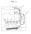
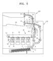
- FIGS. 2 through 5 illustrate a recording medium P that is being transported in the image forming apparatus according to an embodiment of the present general inventive concept.
- a first recording medium P1 that is picked up by a pick up roller 11 is passed through the supply path A by the transporting roller 13 to be transported toward the printing path B.
- the first recording medium P1 passes through the printing path B, an image is formed on a surface of the first recording medium P1 by the printing unit 30.
- the first recording medium P1 on one surface of which an image is formed, is transported to the reverse path C.
- the first guide member 111 that is disposed in the connection portion 110, in which the printing path B, the reverse path C, the discharge path E, and the resupply path D cross, is at the first position 111a to guide the first recording medium P1 to the reverse path C. Accordingly, the discharge path E is blocked, and the reverse path C is opened.
- the first recording medium P1 that is guided by the first guide member 111 into the reverse path C is transported in a forward direction. After a terminal edge of the first recording medium P1 passes the fixing unit 80, the first recording medium P1 is transported in a forward direction by the reverse roller 201 and the reverse auxiliary roller 203.
- the first recording medium P1 that reversely travels along the reverse path C is guided to the resupply path D.
- the first guide member 111 disposed at the connection portion 110 rotates anti-clockwise to change to the second position 111b illustrated in FIG. 3 .
- the reverse roller 201 and the reverse auxiliary roller 203 rotate reversely, the first recording medium P1 reversely travels along the reverse path C.
- the first guide member 111 is converted to the second position 111b
- the first recording medium P1 that reversely travels along the reverse path C is guided to the resupply path D.
- a second recording medium P2 that is newly picked up by the pick up roller 11 may pass through the printing path B and an image may be formed on a surface of the second recording medium P2.
- the first recording medium P1 that is guided to the resupply path D passes by the resupply path D to be supplied to the printing path B again.
- the second recording medium P2 passes through the printing path B to be transported to the reverse path C, as illustrated in FIG. 4 .
- the first recording medium P1 that is resupplied to the printing path B is guided to the discharge path E by the printing unit 30 after an image is formed on the other surface of the first recording medium P1, opposite to the surface which was printed previously.
- the second recording medium P2 may reversely travel along the reverse path C to be transported to the resupply path D. Because the image forming apparatus according to the current embodiment of the present general inventive concept includes the reverse path C, which is a single path, the first recording medium P1 on which printing is completed and the second recording medium P2 that is reversed may simultaneously pass through the connection portion 110.
- the first guide member 111 is disposed at the second position 111b illustrated in FIG. 5 . Because the first guide member 111 is disposed at the second position 111b, the first recording medium P1 on which printing is completed is guided to the discharge path E, and the reversed second recording medium P2 is guided to the resupply path D.
- An image forming apparatus may be divided into a main body unit 100 and a reverse unit 200 that is detachably attached to the main body unit 100.
- the main body unit 100 may include the printing path B, the discharge path E, and the resupply path D
- the reverse unit 200 may include the reverse roller 201 and the reverse path C.
- the image forming apparatus according to the current embodiment of the present general inventive concept is the same as the image forming apparatus according to the previous embodiment except that the reverse unit 200 is detachably attached to the main body unit 100. Thus, description of the same components and configurations as in the previous embodiment is not provided.
- FIG. 6 is a cross-sectional view illustrating an image forming apparatus from which a reverse unit is detached, according to another embodiment of the present general inventive concept.
- double-sided printing may also be performed even when the reverse unit 200 is detached.
- a second guide member 113 is disposed in the connection portion 110, and the discharge roller 21 discharges in the discharge path E.
- the second guide member 113 may be at a third position 113a (see FIG. 7 ) through which a recording medium P that has passed through a printing path B is guided to the discharge path E, or at a fourth position 113b (see FIG. 8 ) through which the recording medium P that reversely travels along the discharge path E is guided to the resupply path D.
- the second guide member 113 may be moved at the fourth position 113b by gravity. In this case, the second guide member 113 is changed to the third position 113a by the discharging recording medium P. After the recording medium P is discharged, the second guide member 113 may return to the fourth position 113b by gravity.
- the second guide member 113 may be elastically biased at the fourth position 113b by an elastic member (not shown). In this case, the second guide member 113 is moved to the third position 113a by the discharging recording medium P. After the recording medium P is discharged, the second guide member 113 may return to the fourth position 113b by an elastic force of the elastic member.
- the first guide member 111 may be at the second position 111b through which the recording medium P is guided to the discharge path E.
- the first guide member 111 and the second guide member 113 may have an alternating structure so as not to interfere with each other if the first guide member 111 is at the second position 111b and the second guide member 113 is at the third position 113a, as is described in detail below.
- the discharge roller 21 may rotate in a forward or reverse direction. As the discharge roller 21 first rotates forwardly and then reversely in order to reverse the recording medium P, the recording medium P that has passed through the printing path B is first transported in the forward direction, and then again in the reverse direction to be guided to the resupply path D.
- the recording medium P that is guided to the resupply path D passes through the printing path B again, thereby forming images on both sides of the recording medium P.
- the recording medium P, on two surfaces of which an image is formed, passes through the discharge path E to be discharged.
- the recording medium P is reversed through the reverse path C to perform double-sided printing, as in the embodiment described with reference to FIGS. 2 through 5 .
- the reverse unit 200 mounted on the main body unit 100, when a first recording medium P1 is transported to the reverse path C, the second guide member 113 is pushed by the transporting first recording medium P1 and is rotated clockwise as illustrated in FIG. 2 . After the first recording medium P1 passes the second guide member 113, the second guide member 113 rotates counterclockwise by gravity or by an elastic force of an elastic member (not shown) to return to its original state, as illustrated in FIG. 3 . In addition, when the second recording medium P2 is transported to the reverse path C, the second guide member 113 is pushed by the transporting second recording medium P2 and is rotated clockwise, as illustrated in FIG.
- the second guide member 113 returns to its original state. Also, when the first recording medium P1 and the second recording medium P2 pass simultaneously through the connection portion 110, the first guide member 111 is at the second position 111b and the second guide member 113 is at the third position 113a, as illustrated in FIG. 5 .
- the second guide member 113 may have a structure to interlock with the first guide member 111 so as not to interfere with the first guide member 111.
- FIGS. 7 and 8 are schematic views illustrating a double-sided printing operation with a reverse unit detached from an image forming apparatus.
- a recording medium P passes through the supply path A and the printing path B to be transported to the discharge path E.
- the second guide member 113 is at the third position 113a through which the first recording medium P1 is guided to the discharge path E.
- the first recording medium P1 transported to the discharge path E is discharged to the outside by forward rotation of the discharge roller 21.
- the discharge roller 21 rotates temporarily in a forward direction to expose the first printing medium P1 by a predetermined length to the outside and rotates in a reverse direction again, as illustrated in FIG. 8 , to transport the first recording medium P1 to the resupply path D.
- a second recording medium P2 that is newly picked up by the pickup roller 11 may be transported to the printing path B.
- the second guide member 113 is at the fourth position 113b at which the printing path B may be blocked and the resupply path D may be opened so that the first recording medium P1 transported from the discharge path E does not travel reversely to the printing path B but is transported to the resupply path D.
- the first recording medium P1 that is transported to the resupply path D is transported to the printing path B, and an image is formed on the other surface of the first recording medium P1, where an image had not previously been formed by the printing unit 30.
- the first recording medium P1 on which printing is completed on its two surfaces is guided to the discharge path E by the second guide member 113 at the third position 113a and is discharged to the outside by forward rotation of the discharge roller 21.
- FIG. 9 is a partial perspective view illustrating the first guide member 111 and the second guide member 113 in an image forming apparatus.
- the first guide member 111 and the second guide member 113 are arranged in the connection portion 110 where the printing path B, the discharge path E, the reverse path C, and the resupply path D cross one another.
- the first guide member 111 and the second guide member 113 are arranged in the connection portion 110, which is a narrow space, and thus, may interlock with each other. Because the first guide member 111 and the second guide member 113 interlock with each other, a jam, which may be caused by a gap between the first guide member 111 and the second guide member 113, may be prevented, and the reliability of the recording medium P may be improved.
- the first guide member 111 and the second guide member 113 may interlock with each other in various manners.
- the first guide member 111 and the second guide member 113 may interlock with each other in a zigzag structure.
- a plurality of guide bars of the first guide member 111 may be spaced apart in a lengthwise direction of a rotation axis
- a plurality of guide bars of the second guide member 113 may be arranged in the spaces between the plurality of guide bars of the first guide member 111.
- an image forming apparatus may be a black and white image forming apparatus in which a black toner is used.
- an image forming apparatus may be a black and white image forming apparatus in which a black toner is used.
Landscapes
- Physics & Mathematics (AREA)
- General Physics & Mathematics (AREA)
- Engineering & Computer Science (AREA)
- Mechanical Engineering (AREA)
- Electrophotography Configuration And Component (AREA)
- Separation, Sorting, Adjustment, Or Bending Of Sheets To Be Conveyed (AREA)
- Conveyance By Endless Belt Conveyors (AREA)
- Counters In Electrophotography And Two-Sided Copying (AREA)
Applications Claiming Priority (1)
| Application Number | Priority Date | Filing Date | Title |
|---|---|---|---|
| KR1020110133997A KR101812749B1 (ko) | 2011-12-13 | 2011-12-13 | 화상형성장치 |
Publications (3)
| Publication Number | Publication Date |
|---|---|
| EP2605076A2 true EP2605076A2 (de) | 2013-06-19 |
| EP2605076A3 EP2605076A3 (de) | 2017-04-26 |
| EP2605076B1 EP2605076B1 (de) | 2019-03-13 |
Family
ID=47221905
Family Applications (1)
| Application Number | Title | Priority Date | Filing Date |
|---|---|---|---|
| EP12183765.2A Not-in-force EP2605076B1 (de) | 2011-12-13 | 2012-09-10 | Bilderzeugungsvorrichtung |
Country Status (4)
| Country | Link |
|---|---|
| US (1) | US9150373B2 (de) |
| EP (1) | EP2605076B1 (de) |
| KR (1) | KR101812749B1 (de) |
| CN (1) | CN103163765B (de) |
Cited By (1)
| Publication number | Priority date | Publication date | Assignee | Title |
|---|---|---|---|---|
| CN107352296A (zh) * | 2016-05-10 | 2017-11-17 | 船井电机株式会社 | 打印机 |
Families Citing this family (12)
| Publication number | Priority date | Publication date | Assignee | Title |
|---|---|---|---|---|
| JP6261312B2 (ja) * | 2013-12-05 | 2018-01-17 | キヤノン株式会社 | 画像形成装置 |
| JP6343990B2 (ja) * | 2014-03-24 | 2018-06-20 | 富士ゼロックス株式会社 | 後処理装置 |
| JP6455655B2 (ja) * | 2014-03-27 | 2019-01-23 | セイコーエプソン株式会社 | 記録装置 |
| JP2016132547A (ja) * | 2015-01-21 | 2016-07-25 | ブラザー工業株式会社 | 画像形成装置 |
| JP7009079B2 (ja) * | 2017-05-12 | 2022-01-25 | キヤノン株式会社 | シート収容装置およびプリント装置 |
| JP6624398B2 (ja) * | 2018-06-13 | 2019-12-25 | セイコーエプソン株式会社 | 記録装置 |
| CN109264458B (zh) * | 2018-10-23 | 2024-06-18 | 恒银金融科技股份有限公司 | 一种便于双面打印和扫描的纸质介质处理装置 |
| JP6708988B2 (ja) * | 2018-12-21 | 2020-06-10 | セイコーエプソン株式会社 | 記録装置 |
| JP7346829B2 (ja) * | 2019-01-30 | 2023-09-20 | セイコーエプソン株式会社 | 記録装置 |
| KR20210009518A (ko) * | 2019-07-17 | 2021-01-27 | 휴렛-팩커드 디벨롭먼트 컴퍼니, 엘.피. | 화상형성장치의 냉각 및 공기 정화 구조 |
| TWI765635B (zh) * | 2021-04-01 | 2022-05-21 | 虹光精密工業股份有限公司 | 具有樞轉式翻轉導引機構的事務機 |
| JP2024126727A (ja) * | 2023-03-08 | 2024-09-20 | 京セラドキュメントソリューションズ株式会社 | シート搬送装置及び画像形成装置 |
Family Cites Families (11)
| Publication number | Priority date | Publication date | Assignee | Title |
|---|---|---|---|---|
| US5852764A (en) * | 1996-05-14 | 1998-12-22 | Sharp Kabushiki Kaisha | Sheet post-processing apparatus |
| JP3398064B2 (ja) * | 1998-08-21 | 2003-04-21 | シャープ株式会社 | 画像形成装置 |
| JP3795488B2 (ja) * | 2000-01-31 | 2006-07-12 | シャープ株式会社 | 画像形成装置 |
| US6381442B1 (en) * | 2000-01-31 | 2002-04-30 | Sharp Kabushiki Kaisa | Image forming apparatus with paper post-treatment device |
| JP2003246534A (ja) * | 2001-12-20 | 2003-09-02 | Fuji Xerox Co Ltd | シート排出装置及びこれを用いたシート処理装置 |
| US6882823B2 (en) * | 2002-01-08 | 2005-04-19 | Sharp Kabushiki Kaisha | Image forming system |
| JP4546059B2 (ja) | 2003-09-26 | 2010-09-15 | キヤノン株式会社 | 画像形成装置 |
| US7108260B2 (en) * | 2003-12-19 | 2006-09-19 | Palo Alto Research Center Incorporated | Flexible director paper path module |
| KR20060005765A (ko) | 2004-07-14 | 2006-01-18 | 삼성전자주식회사 | 듀플렉스패스를 스캔패스로 이용할 수 있도록 스캐너가일체화된 복합기 |
| JP2007079215A (ja) * | 2005-09-15 | 2007-03-29 | Fuji Xerox Co Ltd | 画像形成装置 |
| JP5103226B2 (ja) * | 2007-07-31 | 2012-12-19 | 株式会社リコー | 画像形成装置 |
-
2011
- 2011-12-13 KR KR1020110133997A patent/KR101812749B1/ko not_active Expired - Fee Related
-
2012
- 2012-07-27 US US13/560,367 patent/US9150373B2/en active Active
- 2012-09-10 EP EP12183765.2A patent/EP2605076B1/de not_active Not-in-force
- 2012-12-13 CN CN201210539167.6A patent/CN103163765B/zh not_active Expired - Fee Related
Non-Patent Citations (1)
| Title |
|---|
| None |
Cited By (2)
| Publication number | Priority date | Publication date | Assignee | Title |
|---|---|---|---|---|
| CN107352296A (zh) * | 2016-05-10 | 2017-11-17 | 船井电机株式会社 | 打印机 |
| EP3251860A1 (de) * | 2016-05-10 | 2017-12-06 | Funai Electric Co., Ltd. | Drucker |
Also Published As
| Publication number | Publication date |
|---|---|
| CN103163765B (zh) | 2017-01-18 |
| US9150373B2 (en) | 2015-10-06 |
| EP2605076A3 (de) | 2017-04-26 |
| EP2605076B1 (de) | 2019-03-13 |
| KR101812749B1 (ko) | 2017-12-28 |
| KR20130067133A (ko) | 2013-06-21 |
| CN103163765A (zh) | 2013-06-19 |
| US20130149018A1 (en) | 2013-06-13 |
Similar Documents
| Publication | Publication Date | Title |
|---|---|---|
| EP2605076B1 (de) | Bilderzeugungsvorrichtung | |
| US7062207B2 (en) | Powder transport apparatus and image forming apparatus that can stabilize replenishment of powder | |
| JP2010064804A (ja) | 給紙装置及び画像形成装置 | |
| JP2009051579A (ja) | 記録媒体搬送経路構造および画像形成装置 | |
| US10139755B2 (en) | Developing device with side by side developing sections, and image forming apparatus with same | |
| US8909112B2 (en) | Image forming apparatus having support members with predetermined electric potentials | |
| JP2010001156A (ja) | 記録媒体反転装置及び画像形成装置 | |
| JP4980856B2 (ja) | 記録媒体搬送経路構造及び画像形成装置 | |
| JP2008275804A (ja) | 現像装置、プロセスカートリッジ、画像形成装置及び現像剤搬送スクリュ駆動方法 | |
| JP7476981B2 (ja) | シート搬送装置、およびシート搬送装置を備える画像形成装置 | |
| JP5206269B2 (ja) | 転写ベルト駆動装置および画像形成装置 | |
| JP2009192704A (ja) | 画像形成装置 | |
| JP2019156614A (ja) | シート搬送装置およびそれを備えた画像形成装置 | |
| JP4561267B2 (ja) | 画像形成装置 | |
| US20070189791A1 (en) | Image forming method, image forming device, and image forming program | |
| JP5544890B2 (ja) | 現像装置、画像形成装置及びプロセスカートリッジ | |
| JP7155857B2 (ja) | 画像形成装置 | |
| US20260086485A1 (en) | Sheet accommodation device and image forming apparatus | |
| JP5961729B2 (ja) | 給紙装置、およびこれを備えた画像読取装置、画像形成装置 | |
| JP2013088643A (ja) | 画像形成装置 | |
| US20250074727A1 (en) | Sheet feed device and image forming apparatus | |
| JP7635534B2 (ja) | 画像形成装置 | |
| US20060219114A1 (en) | Sheet transport mechanism for image forming device | |
| JP2008162744A (ja) | 画像形成装置 | |
| JP2010202311A (ja) | 給紙装置、画像形成装置 |
Legal Events
| Date | Code | Title | Description |
|---|---|---|---|
| PUAI | Public reference made under article 153(3) epc to a published international application that has entered the european phase |
Free format text: ORIGINAL CODE: 0009012 |
|
| AK | Designated contracting states |
Kind code of ref document: A2 Designated state(s): AL AT BE BG CH CY CZ DE DK EE ES FI FR GB GR HR HU IE IS IT LI LT LU LV MC MK MT NL NO PL PT RO RS SE SI SK SM TR |
|
| AX | Request for extension of the european patent |
Extension state: BA ME |
|
| RAP1 | Party data changed (applicant data changed or rights of an application transferred) |
Owner name: S-PRINTING SOLUTION CO., LTD. |
|
| PUAL | Search report despatched |
Free format text: ORIGINAL CODE: 0009013 |
|
| AK | Designated contracting states |
Kind code of ref document: A3 Designated state(s): AL AT BE BG CH CY CZ DE DK EE ES FI FR GB GR HR HU IE IS IT LI LT LU LV MC MK MT NL NO PL PT RO RS SE SI SK SM TR |
|
| AX | Request for extension of the european patent |
Extension state: BA ME |
|
| RIC1 | Information provided on ipc code assigned before grant |
Ipc: B41J 3/60 20060101ALI20170320BHEP Ipc: G03G 15/00 20060101ALI20170320BHEP Ipc: G03G 15/23 20060101AFI20170320BHEP Ipc: B41J 13/00 20060101ALI20170320BHEP |
|
| STAA | Information on the status of an ep patent application or granted ep patent |
Free format text: STATUS: REQUEST FOR EXAMINATION WAS MADE |
|
| 17P | Request for examination filed |
Effective date: 20170718 |
|
| RBV | Designated contracting states (corrected) |
Designated state(s): AL AT BE BG CH CY CZ DE DK EE ES FI FR GB GR HR HU IE IS IT LI LT LU LV MC MK MT NL NO PL PT RO RS SE SI SK SM TR |
|
| RAP1 | Party data changed (applicant data changed or rights of an application transferred) |
Owner name: HP PRINTING KOREA CO., LTD. |
|
| GRAP | Despatch of communication of intention to grant a patent |
Free format text: ORIGINAL CODE: EPIDOSNIGR1 |
|
| STAA | Information on the status of an ep patent application or granted ep patent |
Free format text: STATUS: GRANT OF PATENT IS INTENDED |
|
| INTG | Intention to grant announced |
Effective date: 20181220 |
|
| GRAS | Grant fee paid |
Free format text: ORIGINAL CODE: EPIDOSNIGR3 |
|
| GRAA | (expected) grant |
Free format text: ORIGINAL CODE: 0009210 |
|
| STAA | Information on the status of an ep patent application or granted ep patent |
Free format text: STATUS: THE PATENT HAS BEEN GRANTED |
|
| RIN1 | Information on inventor provided before grant (corrected) |
Inventor name: OH, MYUNG-HUN Inventor name: JEONG, JEWON |
|
| AK | Designated contracting states |
Kind code of ref document: B1 Designated state(s): AL AT BE BG CH CY CZ DE DK EE ES FI FR GB GR HR HU IE IS IT LI LT LU LV MC MK MT NL NO PL PT RO RS SE SI SK SM TR |
|
| REG | Reference to a national code |
Ref country code: GB Ref legal event code: FG4D |
|
| REG | Reference to a national code |
Ref country code: CH Ref legal event code: EP Ref country code: AT Ref legal event code: REF Ref document number: 1108534 Country of ref document: AT Kind code of ref document: T Effective date: 20190315 |
|
| REG | Reference to a national code |
Ref country code: IE Ref legal event code: FG4D |
|
| REG | Reference to a national code |
Ref country code: DE Ref legal event code: R096 Ref document number: 602012057680 Country of ref document: DE |
|
| REG | Reference to a national code |
Ref country code: NL Ref legal event code: MP Effective date: 20190313 |
|
| REG | Reference to a national code |
Ref country code: LT Ref legal event code: MG4D |
|
| PG25 | Lapsed in a contracting state [announced via postgrant information from national office to epo] |
Ref country code: SE Free format text: LAPSE BECAUSE OF FAILURE TO SUBMIT A TRANSLATION OF THE DESCRIPTION OR TO PAY THE FEE WITHIN THE PRESCRIBED TIME-LIMIT Effective date: 20190313 Ref country code: LT Free format text: LAPSE BECAUSE OF FAILURE TO SUBMIT A TRANSLATION OF THE DESCRIPTION OR TO PAY THE FEE WITHIN THE PRESCRIBED TIME-LIMIT Effective date: 20190313 Ref country code: NO Free format text: LAPSE BECAUSE OF FAILURE TO SUBMIT A TRANSLATION OF THE DESCRIPTION OR TO PAY THE FEE WITHIN THE PRESCRIBED TIME-LIMIT Effective date: 20190613 Ref country code: FI Free format text: LAPSE BECAUSE OF FAILURE TO SUBMIT A TRANSLATION OF THE DESCRIPTION OR TO PAY THE FEE WITHIN THE PRESCRIBED TIME-LIMIT Effective date: 20190313 |
|
| PG25 | Lapsed in a contracting state [announced via postgrant information from national office to epo] |
Ref country code: RS Free format text: LAPSE BECAUSE OF FAILURE TO SUBMIT A TRANSLATION OF THE DESCRIPTION OR TO PAY THE FEE WITHIN THE PRESCRIBED TIME-LIMIT Effective date: 20190313 Ref country code: BG Free format text: LAPSE BECAUSE OF FAILURE TO SUBMIT A TRANSLATION OF THE DESCRIPTION OR TO PAY THE FEE WITHIN THE PRESCRIBED TIME-LIMIT Effective date: 20190613 Ref country code: NL Free format text: LAPSE BECAUSE OF FAILURE TO SUBMIT A TRANSLATION OF THE DESCRIPTION OR TO PAY THE FEE WITHIN THE PRESCRIBED TIME-LIMIT Effective date: 20190313 Ref country code: HR Free format text: LAPSE BECAUSE OF FAILURE TO SUBMIT A TRANSLATION OF THE DESCRIPTION OR TO PAY THE FEE WITHIN THE PRESCRIBED TIME-LIMIT Effective date: 20190313 Ref country code: LV Free format text: LAPSE BECAUSE OF FAILURE TO SUBMIT A TRANSLATION OF THE DESCRIPTION OR TO PAY THE FEE WITHIN THE PRESCRIBED TIME-LIMIT Effective date: 20190313 Ref country code: GR Free format text: LAPSE BECAUSE OF FAILURE TO SUBMIT A TRANSLATION OF THE DESCRIPTION OR TO PAY THE FEE WITHIN THE PRESCRIBED TIME-LIMIT Effective date: 20190614 |
|
| REG | Reference to a national code |
Ref country code: AT Ref legal event code: MK05 Ref document number: 1108534 Country of ref document: AT Kind code of ref document: T Effective date: 20190313 |
|
| PG25 | Lapsed in a contracting state [announced via postgrant information from national office to epo] |
Ref country code: CZ Free format text: LAPSE BECAUSE OF FAILURE TO SUBMIT A TRANSLATION OF THE DESCRIPTION OR TO PAY THE FEE WITHIN THE PRESCRIBED TIME-LIMIT Effective date: 20190313 Ref country code: IT Free format text: LAPSE BECAUSE OF FAILURE TO SUBMIT A TRANSLATION OF THE DESCRIPTION OR TO PAY THE FEE WITHIN THE PRESCRIBED TIME-LIMIT Effective date: 20190313 Ref country code: PT Free format text: LAPSE BECAUSE OF FAILURE TO SUBMIT A TRANSLATION OF THE DESCRIPTION OR TO PAY THE FEE WITHIN THE PRESCRIBED TIME-LIMIT Effective date: 20190713 Ref country code: AL Free format text: LAPSE BECAUSE OF FAILURE TO SUBMIT A TRANSLATION OF THE DESCRIPTION OR TO PAY THE FEE WITHIN THE PRESCRIBED TIME-LIMIT Effective date: 20190313 Ref country code: SK Free format text: LAPSE BECAUSE OF FAILURE TO SUBMIT A TRANSLATION OF THE DESCRIPTION OR TO PAY THE FEE WITHIN THE PRESCRIBED TIME-LIMIT Effective date: 20190313 Ref country code: EE Free format text: LAPSE BECAUSE OF FAILURE TO SUBMIT A TRANSLATION OF THE DESCRIPTION OR TO PAY THE FEE WITHIN THE PRESCRIBED TIME-LIMIT Effective date: 20190313 Ref country code: ES Free format text: LAPSE BECAUSE OF FAILURE TO SUBMIT A TRANSLATION OF THE DESCRIPTION OR TO PAY THE FEE WITHIN THE PRESCRIBED TIME-LIMIT Effective date: 20190313 Ref country code: RO Free format text: LAPSE BECAUSE OF FAILURE TO SUBMIT A TRANSLATION OF THE DESCRIPTION OR TO PAY THE FEE WITHIN THE PRESCRIBED TIME-LIMIT Effective date: 20190313 |
|
| PG25 | Lapsed in a contracting state [announced via postgrant information from national office to epo] |
Ref country code: SM Free format text: LAPSE BECAUSE OF FAILURE TO SUBMIT A TRANSLATION OF THE DESCRIPTION OR TO PAY THE FEE WITHIN THE PRESCRIBED TIME-LIMIT Effective date: 20190313 Ref country code: PL Free format text: LAPSE BECAUSE OF FAILURE TO SUBMIT A TRANSLATION OF THE DESCRIPTION OR TO PAY THE FEE WITHIN THE PRESCRIBED TIME-LIMIT Effective date: 20190313 |
|
| REG | Reference to a national code |
Ref country code: DE Ref legal event code: R097 Ref document number: 602012057680 Country of ref document: DE |
|
| REG | Reference to a national code |
Ref country code: DE Ref legal event code: R082 Ref document number: 602012057680 Country of ref document: DE Representative=s name: SCHOPPE, ZIMMERMANN, STOECKELER, ZINKLER, SCHE, DE Ref country code: DE Ref legal event code: R081 Ref document number: 602012057680 Country of ref document: DE Owner name: HEWLETT-PACKARD DEVELOPMENT COMPANY, L.P., SPR, US Free format text: FORMER OWNER: HP PRINTING KOREA CO., LTD., SUWON-SI, GYEONGGI-DO, KR |
|
| PG25 | Lapsed in a contracting state [announced via postgrant information from national office to epo] |
Ref country code: IS Free format text: LAPSE BECAUSE OF FAILURE TO SUBMIT A TRANSLATION OF THE DESCRIPTION OR TO PAY THE FEE WITHIN THE PRESCRIBED TIME-LIMIT Effective date: 20190713 Ref country code: AT Free format text: LAPSE BECAUSE OF FAILURE TO SUBMIT A TRANSLATION OF THE DESCRIPTION OR TO PAY THE FEE WITHIN THE PRESCRIBED TIME-LIMIT Effective date: 20190313 |
|
| PLBE | No opposition filed within time limit |
Free format text: ORIGINAL CODE: 0009261 |
|
| STAA | Information on the status of an ep patent application or granted ep patent |
Free format text: STATUS: NO OPPOSITION FILED WITHIN TIME LIMIT |
|
| PG25 | Lapsed in a contracting state [announced via postgrant information from national office to epo] |
Ref country code: DK Free format text: LAPSE BECAUSE OF FAILURE TO SUBMIT A TRANSLATION OF THE DESCRIPTION OR TO PAY THE FEE WITHIN THE PRESCRIBED TIME-LIMIT Effective date: 20190313 |
|
| 26N | No opposition filed |
Effective date: 20191216 |
|
| PG25 | Lapsed in a contracting state [announced via postgrant information from national office to epo] |
Ref country code: SI Free format text: LAPSE BECAUSE OF FAILURE TO SUBMIT A TRANSLATION OF THE DESCRIPTION OR TO PAY THE FEE WITHIN THE PRESCRIBED TIME-LIMIT Effective date: 20190313 |
|
| PG25 | Lapsed in a contracting state [announced via postgrant information from national office to epo] |
Ref country code: TR Free format text: LAPSE BECAUSE OF FAILURE TO SUBMIT A TRANSLATION OF THE DESCRIPTION OR TO PAY THE FEE WITHIN THE PRESCRIBED TIME-LIMIT Effective date: 20190313 |
|
| PG25 | Lapsed in a contracting state [announced via postgrant information from national office to epo] |
Ref country code: MC Free format text: LAPSE BECAUSE OF FAILURE TO SUBMIT A TRANSLATION OF THE DESCRIPTION OR TO PAY THE FEE WITHIN THE PRESCRIBED TIME-LIMIT Effective date: 20190313 |
|
| REG | Reference to a national code |
Ref country code: CH Ref legal event code: PL |
|
| PG25 | Lapsed in a contracting state [announced via postgrant information from national office to epo] |
Ref country code: IE Free format text: LAPSE BECAUSE OF NON-PAYMENT OF DUE FEES Effective date: 20190910 Ref country code: CH Free format text: LAPSE BECAUSE OF NON-PAYMENT OF DUE FEES Effective date: 20190930 Ref country code: LU Free format text: LAPSE BECAUSE OF NON-PAYMENT OF DUE FEES Effective date: 20190910 Ref country code: LI Free format text: LAPSE BECAUSE OF NON-PAYMENT OF DUE FEES Effective date: 20190930 |
|
| REG | Reference to a national code |
Ref country code: BE Ref legal event code: MM Effective date: 20190930 |
|
| PG25 | Lapsed in a contracting state [announced via postgrant information from national office to epo] |
Ref country code: BE Free format text: LAPSE BECAUSE OF NON-PAYMENT OF DUE FEES Effective date: 20190930 |
|
| REG | Reference to a national code |
Ref country code: GB Ref legal event code: 732E Free format text: REGISTERED BETWEEN 20200917 AND 20200923 |
|
| PGFP | Annual fee paid to national office [announced via postgrant information from national office to epo] |
Ref country code: FR Payment date: 20201214 Year of fee payment: 10 |
|
| PG25 | Lapsed in a contracting state [announced via postgrant information from national office to epo] |
Ref country code: CY Free format text: LAPSE BECAUSE OF FAILURE TO SUBMIT A TRANSLATION OF THE DESCRIPTION OR TO PAY THE FEE WITHIN THE PRESCRIBED TIME-LIMIT Effective date: 20190313 |
|
| PG25 | Lapsed in a contracting state [announced via postgrant information from national office to epo] |
Ref country code: HU Free format text: LAPSE BECAUSE OF FAILURE TO SUBMIT A TRANSLATION OF THE DESCRIPTION OR TO PAY THE FEE WITHIN THE PRESCRIBED TIME-LIMIT; INVALID AB INITIO Effective date: 20120910 Ref country code: MT Free format text: LAPSE BECAUSE OF FAILURE TO SUBMIT A TRANSLATION OF THE DESCRIPTION OR TO PAY THE FEE WITHIN THE PRESCRIBED TIME-LIMIT Effective date: 20190313 |
|
| PGFP | Annual fee paid to national office [announced via postgrant information from national office to epo] |
Ref country code: DE Payment date: 20201214 Year of fee payment: 10 Ref country code: GB Payment date: 20210820 Year of fee payment: 10 |
|
| PG25 | Lapsed in a contracting state [announced via postgrant information from national office to epo] |
Ref country code: MK Free format text: LAPSE BECAUSE OF FAILURE TO SUBMIT A TRANSLATION OF THE DESCRIPTION OR TO PAY THE FEE WITHIN THE PRESCRIBED TIME-LIMIT Effective date: 20190313 |
|
| REG | Reference to a national code |
Ref country code: DE Ref legal event code: R119 Ref document number: 602012057680 Country of ref document: DE |
|
| GBPC | Gb: european patent ceased through non-payment of renewal fee |
Effective date: 20220910 |
|
| PG25 | Lapsed in a contracting state [announced via postgrant information from national office to epo] |
Ref country code: FR Free format text: LAPSE BECAUSE OF NON-PAYMENT OF DUE FEES Effective date: 20220930 Ref country code: DE Free format text: LAPSE BECAUSE OF NON-PAYMENT OF DUE FEES Effective date: 20230401 |
|
| PG25 | Lapsed in a contracting state [announced via postgrant information from national office to epo] |
Ref country code: GB Free format text: LAPSE BECAUSE OF NON-PAYMENT OF DUE FEES Effective date: 20220910 |