EP2604843B1 - Tête de piston dotée d'une partie de guidage du combustible - Google Patents
Tête de piston dotée d'une partie de guidage du combustible Download PDFInfo
- Publication number
- EP2604843B1 EP2604843B1 EP11193310.7A EP11193310A EP2604843B1 EP 2604843 B1 EP2604843 B1 EP 2604843B1 EP 11193310 A EP11193310 A EP 11193310A EP 2604843 B1 EP2604843 B1 EP 2604843B1
- Authority
- EP
- European Patent Office
- Prior art keywords
- fuel
- feeding passage
- cylinder head
- fuel feeding
- mixing chamber
- Prior art date
- Legal status (The legal status is an assumption and is not a legal conclusion. Google has not performed a legal analysis and makes no representation as to the accuracy of the status listed.)
- Active
Links
- 239000000446 fuel Substances 0.000 title claims description 400
- 238000002156 mixing Methods 0.000 claims description 75
- 238000002485 combustion reaction Methods 0.000 claims description 25
- 238000004519 manufacturing process Methods 0.000 claims description 14
- 238000000034 method Methods 0.000 claims description 12
- 239000007788 liquid Substances 0.000 claims description 11
- 238000005266 casting Methods 0.000 claims description 7
- 239000000463 material Substances 0.000 claims description 7
- 239000004576 sand Substances 0.000 claims description 5
- 238000001816 cooling Methods 0.000 claims description 2
- 230000035611 feeding Effects 0.000 description 97
- 230000007704 transition Effects 0.000 description 13
- 239000000203 mixture Substances 0.000 description 7
- 238000010276 construction Methods 0.000 description 5
- 230000006698 induction Effects 0.000 description 3
- QGZKDVFQNNGYKY-UHFFFAOYSA-N Ammonia Chemical compound N QGZKDVFQNNGYKY-UHFFFAOYSA-N 0.000 description 2
- 229910001018 Cast iron Inorganic materials 0.000 description 2
- 239000002283 diesel fuel Substances 0.000 description 2
- 238000002347 injection Methods 0.000 description 2
- 239000007924 injection Substances 0.000 description 2
- XEEYBQQBJWHFJM-UHFFFAOYSA-N iron Substances [Fe] XEEYBQQBJWHFJM-UHFFFAOYSA-N 0.000 description 2
- 229910052742 iron Inorganic materials 0.000 description 2
- 229910001208 Crucible steel Inorganic materials 0.000 description 1
- 229910021529 ammonia Inorganic materials 0.000 description 1
- 230000003197 catalytic effect Effects 0.000 description 1
- 238000004891 communication Methods 0.000 description 1
- 230000006378 damage Effects 0.000 description 1
- 238000009826 distribution Methods 0.000 description 1
- 230000000694 effects Effects 0.000 description 1
- 239000007849 furan resin Substances 0.000 description 1
- 231100001231 less toxic Toxicity 0.000 description 1
- 238000012986 modification Methods 0.000 description 1
- 230000004048 modification Effects 0.000 description 1
- 231100000252 nontoxic Toxicity 0.000 description 1
- 230000003000 nontoxic effect Effects 0.000 description 1
- 238000005480 shot peening Methods 0.000 description 1
- 239000010959 steel Substances 0.000 description 1
- 239000000057 synthetic resin Substances 0.000 description 1
- 229920003002 synthetic resin Polymers 0.000 description 1
- 231100000331 toxic Toxicity 0.000 description 1
- 230000002588 toxic effect Effects 0.000 description 1
- 239000003440 toxic substance Substances 0.000 description 1
- 239000001993 wax Substances 0.000 description 1
Images


Classifications
-
- F—MECHANICAL ENGINEERING; LIGHTING; HEATING; WEAPONS; BLASTING
- F02—COMBUSTION ENGINES; HOT-GAS OR COMBUSTION-PRODUCT ENGINE PLANTS
- F02F—CYLINDERS, PISTONS OR CASINGS, FOR COMBUSTION ENGINES; ARRANGEMENTS OF SEALINGS IN COMBUSTION ENGINES
- F02F1/00—Cylinders; Cylinder heads
- F02F1/24—Cylinder heads
- F02F1/243—Cylinder heads and inlet or exhaust manifolds integrally cast together
-
- F—MECHANICAL ENGINEERING; LIGHTING; HEATING; WEAPONS; BLASTING
- F02—COMBUSTION ENGINES; HOT-GAS OR COMBUSTION-PRODUCT ENGINE PLANTS
- F02M—SUPPLYING COMBUSTION ENGINES IN GENERAL WITH COMBUSTIBLE MIXTURES OR CONSTITUENTS THEREOF
- F02M35/00—Combustion-air cleaners, air intakes, intake silencers, or induction systems specially adapted for, or arranged on, internal-combustion engines
- F02M35/10—Air intakes; Induction systems
- F02M35/10209—Fluid connections to the air intake system; their arrangement of pipes, valves or the like
- F02M35/10216—Fuel injectors; Fuel pipes or rails; Fuel pumps or pressure regulators
-
- F—MECHANICAL ENGINEERING; LIGHTING; HEATING; WEAPONS; BLASTING
- F02—COMBUSTION ENGINES; HOT-GAS OR COMBUSTION-PRODUCT ENGINE PLANTS
- F02F—CYLINDERS, PISTONS OR CASINGS, FOR COMBUSTION ENGINES; ARRANGEMENTS OF SEALINGS IN COMBUSTION ENGINES
- F02F1/00—Cylinders; Cylinder heads
- F02F1/24—Cylinder heads
- F02F1/42—Shape or arrangement of intake or exhaust channels in cylinder heads
- F02F1/4235—Shape or arrangement of intake or exhaust channels in cylinder heads of intake channels
-
- F—MECHANICAL ENGINEERING; LIGHTING; HEATING; WEAPONS; BLASTING
- F02—COMBUSTION ENGINES; HOT-GAS OR COMBUSTION-PRODUCT ENGINE PLANTS
- F02M—SUPPLYING COMBUSTION ENGINES IN GENERAL WITH COMBUSTIBLE MIXTURES OR CONSTITUENTS THEREOF
- F02M21/00—Apparatus for supplying engines with non-liquid fuels, e.g. gaseous fuels stored in liquid form
- F02M21/02—Apparatus for supplying engines with non-liquid fuels, e.g. gaseous fuels stored in liquid form for gaseous fuels
- F02M21/0218—Details on the gaseous fuel supply system, e.g. tanks, valves, pipes, pumps, rails, injectors or mixers
- F02M21/0248—Injectors
- F02M21/0281—Adapters, sockets or the like to mount injection valves onto engines; Fuel guiding passages between injectors and the air intake system or the combustion chamber
-
- F—MECHANICAL ENGINEERING; LIGHTING; HEATING; WEAPONS; BLASTING
- F02—COMBUSTION ENGINES; HOT-GAS OR COMBUSTION-PRODUCT ENGINE PLANTS
- F02M—SUPPLYING COMBUSTION ENGINES IN GENERAL WITH COMBUSTIBLE MIXTURES OR CONSTITUENTS THEREOF
- F02M21/00—Apparatus for supplying engines with non-liquid fuels, e.g. gaseous fuels stored in liquid form
- F02M21/02—Apparatus for supplying engines with non-liquid fuels, e.g. gaseous fuels stored in liquid form for gaseous fuels
- F02M21/0218—Details on the gaseous fuel supply system, e.g. tanks, valves, pipes, pumps, rails, injectors or mixers
- F02M21/0296—Manufacturing or assembly; Materials, e.g. coatings
-
- F—MECHANICAL ENGINEERING; LIGHTING; HEATING; WEAPONS; BLASTING
- F02—COMBUSTION ENGINES; HOT-GAS OR COMBUSTION-PRODUCT ENGINE PLANTS
- F02M—SUPPLYING COMBUSTION ENGINES IN GENERAL WITH COMBUSTIBLE MIXTURES OR CONSTITUENTS THEREOF
- F02M21/00—Apparatus for supplying engines with non-liquid fuels, e.g. gaseous fuels stored in liquid form
- F02M21/02—Apparatus for supplying engines with non-liquid fuels, e.g. gaseous fuels stored in liquid form for gaseous fuels
- F02M21/04—Gas-air mixing apparatus
- F02M21/042—Mixer comprising a plurality of bores or flow passages
-
- F—MECHANICAL ENGINEERING; LIGHTING; HEATING; WEAPONS; BLASTING
- F02—COMBUSTION ENGINES; HOT-GAS OR COMBUSTION-PRODUCT ENGINE PLANTS
- F02M—SUPPLYING COMBUSTION ENGINES IN GENERAL WITH COMBUSTIBLE MIXTURES OR CONSTITUENTS THEREOF
- F02M35/00—Combustion-air cleaners, air intakes, intake silencers, or induction systems specially adapted for, or arranged on, internal-combustion engines
- F02M35/10—Air intakes; Induction systems
- F02M35/1034—Manufacturing and assembling intake systems
- F02M35/10347—Moulding, casting or the like
-
- F—MECHANICAL ENGINEERING; LIGHTING; HEATING; WEAPONS; BLASTING
- F02—COMBUSTION ENGINES; HOT-GAS OR COMBUSTION-PRODUCT ENGINE PLANTS
- F02M—SUPPLYING COMBUSTION ENGINES IN GENERAL WITH COMBUSTIBLE MIXTURES OR CONSTITUENTS THEREOF
- F02M61/00—Fuel-injectors not provided for in groups F02M39/00 - F02M57/00 or F02M67/00
- F02M61/14—Arrangements of injectors with respect to engines; Mounting of injectors
- F02M61/145—Arrangements of injectors with respect to engines; Mounting of injectors the injection nozzle opening into the air intake conduit
-
- F—MECHANICAL ENGINEERING; LIGHTING; HEATING; WEAPONS; BLASTING
- F02—COMBUSTION ENGINES; HOT-GAS OR COMBUSTION-PRODUCT ENGINE PLANTS
- F02M—SUPPLYING COMBUSTION ENGINES IN GENERAL WITH COMBUSTIBLE MIXTURES OR CONSTITUENTS THEREOF
- F02M61/00—Fuel-injectors not provided for in groups F02M39/00 - F02M57/00 or F02M67/00
- F02M61/16—Details not provided for in, or of interest apart from, the apparatus of groups F02M61/02 - F02M61/14
- F02M61/18—Injection nozzles, e.g. having valve seats; Details of valve member seated ends, not otherwise provided for
- F02M61/1806—Injection nozzles, e.g. having valve seats; Details of valve member seated ends, not otherwise provided for characterised by the arrangement of discharge orifices, e.g. orientation or size
- F02M61/1826—Discharge orifices having different sizes
-
- Y—GENERAL TAGGING OF NEW TECHNOLOGICAL DEVELOPMENTS; GENERAL TAGGING OF CROSS-SECTIONAL TECHNOLOGIES SPANNING OVER SEVERAL SECTIONS OF THE IPC; TECHNICAL SUBJECTS COVERED BY FORMER USPC CROSS-REFERENCE ART COLLECTIONS [XRACs] AND DIGESTS
- Y02—TECHNOLOGIES OR APPLICATIONS FOR MITIGATION OR ADAPTATION AGAINST CLIMATE CHANGE
- Y02T—CLIMATE CHANGE MITIGATION TECHNOLOGIES RELATED TO TRANSPORTATION
- Y02T10/00—Road transport of goods or passengers
- Y02T10/10—Internal combustion engine [ICE] based vehicles
- Y02T10/12—Improving ICE efficiencies
-
- Y—GENERAL TAGGING OF NEW TECHNOLOGICAL DEVELOPMENTS; GENERAL TAGGING OF CROSS-SECTIONAL TECHNOLOGIES SPANNING OVER SEVERAL SECTIONS OF THE IPC; TECHNICAL SUBJECTS COVERED BY FORMER USPC CROSS-REFERENCE ART COLLECTIONS [XRACs] AND DIGESTS
- Y02—TECHNOLOGIES OR APPLICATIONS FOR MITIGATION OR ADAPTATION AGAINST CLIMATE CHANGE
- Y02T—CLIMATE CHANGE MITIGATION TECHNOLOGIES RELATED TO TRANSPORTATION
- Y02T10/00—Road transport of goods or passengers
- Y02T10/10—Internal combustion engine [ICE] based vehicles
- Y02T10/30—Use of alternative fuels, e.g. biofuels
-
- Y—GENERAL TAGGING OF NEW TECHNOLOGICAL DEVELOPMENTS; GENERAL TAGGING OF CROSS-SECTIONAL TECHNOLOGIES SPANNING OVER SEVERAL SECTIONS OF THE IPC; TECHNICAL SUBJECTS COVERED BY FORMER USPC CROSS-REFERENCE ART COLLECTIONS [XRACs] AND DIGESTS
- Y10—TECHNICAL SUBJECTS COVERED BY FORMER USPC
- Y10T—TECHNICAL SUBJECTS COVERED BY FORMER US CLASSIFICATION
- Y10T29/00—Metal working
- Y10T29/49—Method of mechanical manufacture
- Y10T29/49229—Prime mover or fluid pump making
- Y10T29/4927—Cylinder, cylinder head or engine valve sleeve making
Definitions
- the present disclosure relates to a cylinder head for an internal combustion engine configured to be operated with gaseous or liquid fuel.
- the present disclosure relates to a cylinder head comprising a fuel guiding portion.
- the present disclosure relates to a method for manufacturing a cylinder head of the type mentioned above.
- Internal combustion engines may be provided with at least one cylinder head.
- the cylinder head may be arranged above the cylinders of the internal combustion engine on top of the cylinder block and may include fuel inlet valves, passages for feeding air and fuel to the cylinder, spark plugs, fuel injectors and passages for feeding exhaust gas.
- the fuel to be fed to the cylinders may be mixed with air to allow an efficient combustion.
- the fuel completely mixes with the air, i.e., that the fuel is evenly distributed in the air.
- US 2008/0271700 A1 discloses a cylinder head for an internal combustion engine which includes an air duct for injecting gas into a flow channel.
- the air duct is produced by means of casting.
- EP 0 715 069 A1 discloses an air intake tract element adapted to accommodate an injector and to be fixed to the cylinder head of an engine.
- a cylinder head for an internal combustion engine is further known from FR 2 655 381 A1 .
- DE 36 33 612 A1 discloses a fuel injector to be mounted on a branch of an engine intake manifold.
- the fuel injector has a hollow body with an injection orifice therein and a valve member mounted slidably in the body.
- a sleeve member is mounted on the body to cover an injection orifice of the hollow body. Communication apertures are formed in the outer end of the sleeve member.
- US 5,408,978 A discloses a mixer for entraining gaseous fuel into an air-stream for induction into an internal combustion engine.
- the present disclosure is directed, at least in part, to improving or overcoming one or more aspects of prior systems.
- a cylinder head with at least one fuel guiding section for an internal combustion engine which is configured to be operated with fuel may comprise a fuel inlet valve casing for accommodating a fuel inlet valve configured to control a fuel flow rate, a fuel/air mixing chamber for mixing the fuel with air and a fuel guiding portion connecting the fuel inlet valve casing to the fuel/air mixing chamber.
- the fuel guiding portion may be integrally formed with the cylinder head and defines at least a first fuel feeding passage and at least a second fuel feeding passage, the first fuel feeding passage and the second fuel feeding passage extending from the fuel inlet valve casing to the fuel/air mixing chamber.
- a method for manufacturing a cylinder head for an internal combustion engine configured to be operated with fuel may comprise the following steps:
- Cylinder head 1 may comprise six fuel guiding sections 1A, 1B, 1C, ID, IE, IF. Alternatively, cylinder head 1 may comprise less or more than six fuel guiding sections, for example four, eight or twelve fuel guiding sections.
- Each guiding section 1A, 1B, 1C, ID, IE, IF may be connected to a fuel reservoir 2 via a fuel supply pipe 3.
- Fuel reservoir 2 may be a tank or a container filled with fuel, such as gaseous fuel or liquid fuel, for example diesel fuel.
- each fuel guiding section 1A, 1B, 1C, ID, IE, IF may be connected to an exhaust gas treatment device 4 via an exhaust gas supply pipe 5.
- Exhaust gas treatment device 4 may be a known catalytic converter used to convert toxic exhaust gas emissions from the internal combustion engine into non-toxic or at least less-toxic substances.
- Each fuel guiding section 1A, 1B, 1C, ID, IE, IF may be associated with a cylinder (not shown) of the internal combustion engine.
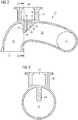
- Fuel guiding section 1A may comprise an air intake chamber 10, a fuel/air mixing chamber 20, a fuel guiding portion 30 and a fuel inlet valve casing 40.
- Air intake chamber 10 may have a bent/curved configuration.
- fuel/air mixing chamber 20 may have a bent/curved configuration.
- both air intake chamber 10 and fuel/air mixing chamber 20 may have a linear or any other suitable configuration.
- Air intake chamber 10 may be integrally formed with fuel guiding section 1A, in particular, with fuel/air mixing chamber 20.
- air intake chamber 10 may be integrally casted on fuel/air mixing chamber 20.
- Fuel/air mixing chamber 20 may have a mixed fuel/air opening 21 disposed at the end of fuel/air mixing chamber 20 opposing the end of fuel/air mixing chamber 20 at which air intake chamber 10 is arranged. Mixed fuel/air opening 21 may connect fluidly fuel/air mixing chamber 20 with one of the cylinders of the internal combustion engine.
- Mixed fuel/air opening 21 may have a circular shape. Alternatively, mixed fuel/air opening 21 may have an elliptical shape or any other suitable shape.
- Air intake chamber 10 may have an air opening 11 disposed at the end of air intake chamber 10 opposing the end at which fuel/air mixing chamber 20 is arranged. Air opening 11 may connect fluidly air intake chamber 10 with an air induction system (not shown). Air opening 11 may have a circular shape. Alternatively, air opening 11 may have an elliptical or any other suitable shape. It should be noted that fuel guiding section 1A may not have air intake chamber 10, but may be connected directly to an air induction system.
- Fuel guiding portion 30 may be integrally formed with fuel guiding section 1A, in particular, with air intake chamber 10 and fuel/air mixing chamber 20.
- fuel guiding portion 30 may be integrally formed with fuel guiding section 1A at a transition position from air intake chamber 10 to fuel/air mixing chamber 20.
- Fuel guiding portion 30 may have a nose- or ridge-like shape.
- fuel guiding portion 30 may have a substantial triangular shape in the cross-sectional view as shown in Fig. 2 .
- Fuel guiding portion 30 may extend into air intake chamber 10 and/or fuel/air mixing chamber 20 such that a first surface portion 31 of fuel guiding portion 30 which faces air intake chamber 10 may run in an up-and-down-direction as viewed in Fig.
- fuel guiding portion 30 may extend obliquely with reference to an up-and-down-direction as viewed in Fig. 2 . Due to the oblique extension of second surface portion 32, second surface portion 32 of fuel guiding portion 30 may form a defined inclined edge. Further, fuel guiding portion 30 may comprise a first fuel feeding passage 33 and a second fuel feeding passage 34. Alternatively, fuel guiding portion 30 may have more than two fuel feeding passages. First fuel feeding passage 33 may obliquely extend through fuel guiding portion 30, i.e., first fuel feeding passage 33 may pass through fuel guiding portion 30 in an inclined manner.
- Second fuel feeding passage 34 may extend through fuel guiding portion 30 in an up-and-down-direction as viewed in Fig. 2 such that first fuel feeding passage 33 is arranged angularly to second fuel feeding passage 34.
- First and second fuel feeding passages 33, 34 may be formed circularly.
- first and second fuel feeding passages 33, 34 may have the same diameter, for example 32 mm.
- first and second fuel feeding passages 33, 34 may have different diameters.
- first fuel feeding passage 33 may have a diameter of 32 mm, in particular, 32.4 mm
- second fuel feeding passage 34 may have a diameter of 37 mm, in particular, 37.2 mm.
- both or at least one of first and second fuel feeding passages 33, 34 may comprise a non-circular cross-section, such as a quadrangular or a polygonal cross-section.
- first and second fuel feeding passages 33, 34 may have the same cross-section or a different cross-section.
- the angle between first and second fuel feeding passages 33, 34 may range between 15° to 17°, preferably 16°.
- the angle between first and second fuel feeding passages 33, 34 may range between 10° and 15° or 17° and 25°.
- Fuel inlet valve casing 40 may be integrally formed with fuel guiding section 1A.
- fuel inlet valve casing 40 may be casted on air intake chamber 10 and fuel/air mixing chamber 20 in the region of the transition position, i.e., at the position where fuel guiding portion 30 is arranged.
- fuel inlet valve casing 40 may be formed as a separate component mechanically connected to fuel/air mixing chamber 20.
- fuel inlet valve casing 40 may be screwed or bolted to fuel/air mixing chamber 20.
- Fuel inlet valve casing 40 may have a substantially rectangular cross-section as viewed in Fig. 2 and may have a cup-like shape. In a bottom portion of fuel inlet valve casing 40, a recess 41 may be formed.
- Recess 41 may have a substantially trapezoid cross-section with sharp edges as viewed as viewed in Fig. 2 .
- recess 41 may have a substantially rectangular shape, for example with sharp edges or round corners, or any other suitable shape.
- Recess 41 may have a circumferential edge 42 spaced from a left casing wall 43 and a right casing wall 44 as viewed in Fig. 2 .
- Recess 41 may be connected fluidly to both first fuel feeding passage 33 and second fuel feeding passage 34. That is, both fuel feeding passages 33, 34 may extend from recess 41 to fuel/air mixing chamber 20 such that fuel inlet valve 50 is connected fluidly to recess 41.
- first and second fuel feeding passages 33, 34 may also be connected fluidly to fuel inlet valve casing 40, in particular, the bottom portion of fuel inlet valve casing 40.
- fuel inlet valve casing 40 may house a fuel inlet valve 50.
- Fuel inlet valve 50 may be disposed in fuel inlet valve casing 40 with a predetermined distance between fuel inlet valve 50 and casing walls 43, 44.
- fuel inlet valve 50 may be inserted into fuel inlet valve casing 40 such that it abuts against casing walls 43, 44.
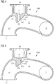
- Fig. 3 a cross-sectional view of fuel guiding section 1A taken along line III-III in Fig. 2 is shown.
- fuel/air mixing chamber 20 may have a circular cross-section.
- fuel/air mixing chamber 20 may have an elliptical or any other suitable cross-section.
- fuel guiding portion 30 may extend into fuel/air mixing chamber 20 and air intake chamber 10 at the transition position, possibly centrally, from an upper portion thereof.
- fuel guiding portion 30 may be equally spaced from an inner wall of fuel/air mixing chamber 20 in a left-right direction as viewed in Fig. 3 and may extend to a center of the circular cross-section of fuel/air mixing chamber 20 at the transition position.
- the lowest point of fuel guiding portion 30 may be disposed in the center of the cross-section of fuel/air mixing chamber 20 and air intake chamber 10 at the transition position.
- the lowest point of fuel guiding portion 30 may be arranged above or below the center of the cross-section of fuel/air mixing chamber 20 and the air intake chamber 10. That is, fuel guiding portion may also be shorter or longer in an up-and-down direction as viewed in Fig. 3 .
- fuel guiding portion may be located closer to the left or the right portion of inner wall 22 of fuel/air mixing chamber 20 in a left-right-direction.
- Fuel guiding section 100A differs from fuel guiding section 1A according to the first embodiment in the construction of the fuel guiding portion. Accordingly, the features of fuel guiding section 100A which are unmodified compared to the features of fuel guiding section 1A are provided with the same reference numerals and their description will be omitted in the following.
- fuel guiding section 100A comprises a fuel guiding portion 130.
- Fuel guiding portion 130 has the same nose- or ridge-like shape as fuel guiding portion 30 with a first surface portion 131 and a second surface portion 132 according to the first embodiment.
- Fuel guiding portion 130 may have a first fuel feeding passage 133 and a second fuel feeding passage 134.
- Fuel guiding portion 130 may have more than two fuel feeding passages 133, 134.
- First fuel feeding passage 133 may extend parallel to second fuel feeding passage 134. Further, first fuel feeding passage 133 may have a smaller cross-section than second fuel feeding passage 134.
- first fuel feeding passage may have a smaller diameter, for example 32 mm, in particular, 32.4 mm, than second fuel feeding passage 134 having for example a diameter of 37 mm, in particular, 37.2 mm.
- first and second fuel feeding passages 133, 134 may have the same cross-section and the same diameter, respectively, such as a diameter between 30 and 40 mm, for example, 34 mm, 36 mm, 38 mm.
- Fuel guiding section 200A differs from fuel guiding section 1A in the construction of the fuel guiding portion. Accordingly, the features of fuel guiding section 200A which are unmodified compared to fuel guiding section 1A are provided with the same reference numerals and there description will be omitted in the following.
- Fuel guiding section 200A may comprise a fuel guiding portion 230.
- Fuel guiding portion 230 may have the same nose- or ridge-like shape as fuel guiding portion 30 with a first surface portion 231 and a second surface portion 232 according to the first embodiment.
- Fuel guiding portion 230 may comprise a first fuel feeding passage 233 and a second fuel feeding passage 234.
- Fuel guiding portion 230 may comprise more than two fuel feeding passages.
- First fuel feeding passage 233 may extend from recess 41 to fuel/air mixing chamber 20 in a curved manner. In other words, first fuel feeding passage 233 may define a passage having a certain radius, and, hence, being not linear.
- Second fuel feeding passage 234 may linearly extend from recess 41 to fuel/air mixing chamber 20.
- second fuel feeding passage 234 or both fuel feeding passages 233, 234 may be curved.
- First fuel feeding passage 233 may have a larger cross-section than second fuel feeding passage 234.
- first fuel feeding passage 233 may have a larger diameter, for example 37 mm, in particular, 37.2 mm, than second fuel feeding passage 234 having for example a diameter of 32 mm, in particular, 32.4 mm.
- first and second fuel feeding passages 233, 234 may have the same cross-section, for example the same diameter, such as a diameter between 30 and 40 mm, for example, 34 mm, 36 mm, 38 mm.
- Fuel guiding section 300A differs from fuel guiding section 1A according to the first embodiment in the construction of the fuel guiding portion. Accordingly, the features of fuel guiding section 300A which are unmodified compared to the features of fuel guiding section 1A are provided with the same reference numerals and their description will be omitted in the following.
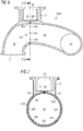
- Fuel guiding section 300A may comprise a fuel guiding portion 330 having an outer connection duct element 361, a circular duct line 362, a first inner connection duct element 363, a second inner connection duct element 364, a third inner connection duct element 365, a fourth inner connection duct element 366, a fifth inner connection duct element 367, a sixth inner connection duct element 368 and a seventh inner connection duct element 369.
- fuel guiding portion 330 may have less than seven inner connection duct elements, for example, two, three, four, five, six or more than seven inner connection duct elements.
- Circular duct line 362 may be arranged within an outer wall portion of fuel guiding section 300A at the transition position of air intake chamber 10 to fuel/air mixing chamber 20.
- Outer connection duct element 361 may connect fluidly circular duct line 362 with recess 41 or, in case no recess 41 is provided, with the bottom portion of fuel inlet valve casing 40.
- each inner connection duct element 363, 364, 365, 366, 367, 368, 369 may connect fluidly circular duct line 362 with fuel/air mixing chamber 20 and air intake chamber 10.
- Inner connection duct elements 364, 365, 366, 367, 368, 369 may extend radial in an inner wall portion of fuel guiding section 300A at the transition position from air intake chamber 10 to fuel/air mixing chamber 20.
- each inner connection duct element 363, 364, 365, 366, 367, 368, 369 may have a smaller cross-section than outer connection duct element 361 and circular duct line 362 which may have the same cross-section or different cross-sections.
- the cross-section of circular duct line 362 may correspond to the cross-sections of all inner connection duct elements 363, 364, 365, 366, 367, 368, 369 together.
- Core 400 may have a bent/curved shape with a cavity 401 located at a position of the smallest radius, that is at a position of the smallest curvature of core 400. Cavity 401 corresponds to the part of core 400 for manufacturing fuel guiding portion 30. Further, core 400 may comprise a boss 402 at a lower left side of the core as viewed in Fig. 8 . Boss 402 may serve as a chaplet for supporting core 400 when being mounted into mold 500. Core 400 may be made of pit-iron sand. Alternatively, core 400 may be made of pit-iron sand mixed with synthetic resin, wax or furan resin.
- Lower portion 501 of a mold 500 is shown.
- Lower portion 501 may be made of any known mold material such as cast iron or steel.
- core 400 may be arranged in lower portion 501.
- Boss 402 may serve as a chaplet for supporting core 400 when being mounted into mold 500.
- Lower portion 501 may have a substantially rectangular outer shape and may, additionally to the contour of fuel guiding section 1A defined by core 400, define further components of the internal combustion engine, which will not be referred to in this description.
- Upper portion of mold 500 is not shown.
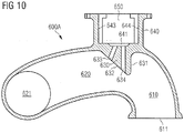
- exhaust gas guiding section 600A is shown.
- Exhaust gas guiding section 600A is constructed in accordance with fuel guiding section 1A.
- exhaust gas guiding section 600A may be constructed in accordance with fuel guiding sections 100A, 200A or 300A.
- Exhaust gas guiding section 600A may comprise an exhaust gas outlet chamber 610 and an exhaust gas/gas mixing chamber 620.
- Exhaust gas outlet chamber 610 may be integrally formed with exhaust gas/gas mixing chamber 620.
- exhaust gas outlet chamber 610 may be casted on exhaust gas/gas mixing chamber 620.
- Exhaust gas outlet chamber 610 may have an exhaust gas opening 611 at an end opposing the end of exhaust gas outlet chamber 610 which defines a transition position from exhaust gas outlet chamber 610 to exhaust gas/gas mixing chamber 620.
- exhaust gas/gas mixing chamber may comprise a mixed exhaust gas/gas opening 621 at an end of exhaust gas/gas mixing chamber which opposes the transition position of exhaust gas outlet chamber 610 to exhaust gas/gas mixing chamber 620.
- Exhaust gas opening 611 may be arranged perpendicularly to mixed exhaust gas/gas opening 621.
- Exhaust gas guiding section 600A may further comprise an exhaust gas guiding portion 630.
- Exhaust gas guiding portion 630 may have a nose- or ridge-like shape. Exhaust gas guiding portion 630 may extend into exhaust gas outlet chamber 610 and exhaust gas/gas mixing chamber 620 at the transition position from exhaust gas outlet chamber 610 to exhaust gas/gas mixing chamber 620.
- exhaust gas guiding portion 630 may have a first surface portion 631 which extends in an up-and-down direction in exhaust gas outlet chamber 610 as viewed in Fig. 10 and a second surface portion 632 which extends obliquely in exhaust gas/gas mixing chamber 620.
- exhaust gas guiding portion 630 may define a substantially triangular shape as viewed in Fig. 10 .
- exhaust gas guiding portion 630 may be arranged such that its first surface which extends in an up-and-down-direction may face exhaust gas/gas mixing chamber 620 and such that its second surface which extends obliquely may face exhaust gas outlet chamber 610.
- gas feeding passages 633, 634 may be directed to exhaust gas opening 611 and may guide gas into exhaust gas outlet chamber 610.
- Exhaust gas guiding portion 630 may comprise a first exhaust gas feeding passage 633 and a second exhaust gas feeding passage 634.
- First exhaust gas feeding passage 633 may be angularly arranged to second exhaust gas feeding passage 634. Further, first exhaust gas feeding passage 633 may be shorter than second exhaust gas feeding passage 634.
- First and second exhaust gas feeding passages 633, 634 may have the same diameter. Alternatively, first and second exhaust gas feeding passages 633, 634 may have different diameters.
- exhaust gas guiding portion may have more than two exhaust gas feeding passages.
- exhaust gas feeding passages 633, 634 may be arranged parallel to each other or at least one of exhaust gas feeding passages 633, 634 may be bent.
- exhaust gas guiding section 600A may comprise a gas inlet valve casing 640.
- Gas inlet valve casing 640 may be arranged in top of exhaust gas guiding portion 630.
- Gas inlet valve casing 640 may comprise a recess 641.
- Recess 641 may be fluidly connected to first and second exhaust gas feeding passages 633, 634.
- Recess 641 may have a substantial trapezoidal cross-section as viewed in Fig. 10 .
- recess 641 may have a substantial rectangular cross-section.
- Gas inlet valve casing 640 may house a gas inlet valve 650.
- Gas inlet valve 650 may be arranged in gas inlet valve casing 640 such that the outer surface of gas inlet valve 650 is spaced from casing walls 643, 644 of gas inlet valve casing 640.
- gas inlet valve 650 may be arranged in gas inlet valve casing 640 such that there is no space between the outer surface of gas inlet valve 650 and casing walls 643, 644 of gas inlet valve casing 640.
- exhaust gas guiding section 600A may also be constructed in accordance with fuel guiding sections 100A, 200A, 300A.
- exhaust gas guiding section 600A may also comprise an exhaust gas guiding portion having a circular duct line, an outer connection duct element and a plurality of inner connection duct elements as with fuel guiding section 300A.
- fuel such as gaseous or liquid fuel, for example diesel fuel
- fuel reservoir 2 such as a tank
- fuel supply pipe 3 to cylinder head 1, in particular, to each fuel guiding section 1A, 1B, 1C, ID, IE, IF for being supplied to the cylinders of the internal combustion engine.
- the fuel may be further supplied through fuel inlet valve 50 which is configured to control a fuel flow rate, for example, to allow or restrict fuel from flowing to the cylinder of the internal combustion engine, and from fuel inlet valve 50 into recess 40.
- the fuel may flow through first fuel feeding passage 33 and second fuel feeding passage 34. After having passed fuel inlet valve 50, the fuel may flow into and may gather itself in recess 41 which is configured to collect a predetermined amount of fuel in order always to allow a steady fuel supply through both of first and second fuel feeding passages 33, 34.
- recess 40 serves as a reservoir for storing fuel in order to provide an equal supply of fuel to both fuel feeding passages 33, 34.
- the fuel may flow into fuel/air mixing chamber 20. In fuel/air mixing chamber 20, the fuel may mix with air, in particular, compressed air, sucked from the outside through air intake chamber 10.
- fuel guiding portion 30 extends obliquely in fuel/air mixing chamber 20 and, thus, defines the defined inclined edge between first fuel feeding passage 33 and second fuel feeding passage 34, the fuel may be swirled in a manner that results in an optimum, i.e., an equal mixture of fuel and air.
- This optimum mixture may further be improved in that fuel guiding portion 30 extends into fuel/air mixing chamber 20 along a vertical centerline in an up-and-down direction as viewed in Fig. 3 .
- the fuel/air mixture may flow to the cylinder of the internal combustion engine where it may be ignited and combusted.
- an optimum, and, hence, equal mixture of fuel and air can be achieved in that the fuel is supplied from fuel inlet valve 50 to fuel/air mixing chamber 20 at a plurality of predetermined positions along a circumference of an inner wall of fuel/air mixing chamber 20 at the transition position from air intake chamber 10 to fuel/air mixing chamber 20.
- Core 400 may be arranged within lower portion 501 of mold 500.
- mold 501 may be filled with a casting material, for example, cast iron.
- the upper portion of mold 500 may be placed on lower portion 501 and the casting material may be cooled down.
- mold 500 and core 400 may be removed.
- mold 501 may be taken away from fuel guiding section 1A.
- Core 400 may be destroyed such that parts of core 400 may be pulled out of fuel guiding section 1A. Destruction of core 400 may be performed by use of pressurized air, shot peening, vibration, knocking, etc.
- two bores may be formed from an upper surface of fuel guiding section 1A at the transition position through fuel guiding portion 30, the two bores defining first and second fuel feeding passages 33, 34.
- the above described method for manufacturing fuel guiding section 1A includes a further step of arranging a further core (not shown) above core 400, the further core having a cylindrical shape.
- the method for manufacturing fuel guiding sections 100A, 200A may be substantially the same as the above described method for manufacturing fuel guiding section 1A.
- the method for manufacturing fuel guiding section 200A may comprise the further step of arranging a further core which has an elongated curved shape for defining curved first fuel feeding passage 233.
- the further core may be made of sand as core 400.
- the method for manufacturing fuel guiding section 300A may comprise the step of arranging a circular duct line 362 around core 400.
- Circular duct line 362 may have an inner diameter larger than an outer diameter of core 400 at the transition position.
- an outer connection duct element 361 and at least two inner connection duct elements may be drilled from the outside of fuel guiding section 300A, in particular, from recess 41, and from the inside into fuel guiding portion 330 to connect fluidly the outside and the inside of fuel guiding section 300A with circular duct line 362.
- exhaust gas guiding section 600A may function in substantially the same manner, except for supplying exhaust gas and not fuel, and may be manufactured in the same manner as a fuel guiding section 1A.
- exhaust gas flowing through exhaust gas outlet chamber 610 and exhaust gas/gas mixing chamber 620 may be mixed with a gas, such as ammonia, before the exhaust gas is supplied to exhaust gas treatment device 4 via exhaust gas pipe 5.
- a gas such as ammonia
- liquids may be guided into the exhaust gas flowing through exhaust gas outlet chamber 610 and exhaust gas/gas mixing chamber 620 by use of a liquid inlet valve instead of gas inlet valve 650.
- an optimal mixture of fuel and air and exhaust gas and gas, respectively may be realized.
- the above-described constructions of a cylinder head an equal distribution of fuel in air and gas in exhaust gas, respectively, may be improved and, consequently, a more complete combustion of the fuel/air mixture and a more effective exhaust gas treatment, respectively, may be achieved because of a defined inclined edge of fuel guiding portion or an edge extending around an inner circumference of the fuel guiding section allowing a defined swirl and defined turbulences, respectively, of the fuel to be mixed with air, in particular, compressed air or the exhaust gas to be mixed with gas.
- the fuel inlet valve casing may be integrally formed with, for example casted on, the cylinder head.
- one of the first fuel feeding passage and the second fuel feeding passage may be shorter than the other one of the first fuel feeding passage and the second fuel feeding passage.
- first fuel feeding passage and the second fuel feeding passage may extend angularly to each other, for example at an angle between 15 and 17 degrees, from the fuel inlet valve casing to the fuel/air mixing chamber.
- first fuel feeding passage and the second fuel feeding passage may extend parallel to each other.
- one of the first fuel feeding passage and the second fuel feeding passage may have a larger cross-section than the other one of the first fuel feeding passage and the second fuel feeding passage.
- At least one of the first fuel feeding passage and the second fuel feeding passage may extend in a curved manner from the fuel inlet valve casing to the fuel/air mixing chamber.
- the first fuel feeding passage and the second fuel feeding passage may define an outer connection duct element, a circular duct line and a first inner connection duct element and a second inner connection duct element, the outer connection duct element fluidly connecting the fuel inlet valve casing with the circular duct line and the first and second inner connection duct elements connecting the circular duct line with the fuel/air mixing chamber.
- the outer connection duct element and the circular duct line may have the same cross-section which is larger than the cross-section of the first and the second inner connection duct elements.
- first fuel feeding passage and the second fuel feeding passage may extend linearly from the fuel inlet valve casing to the fuel/air mixing chamber.
- the cylinder head may further comprise at least one air intake chamber for suctioning air, the air intake chamber being integrally formed with the fuel/air mixing chamber.
- a recess may be formed in a bottom portion of the fuel inlet valve casing, the recess defining a reservoir for fuel and being fluidly connected to the first fuel feeding passage and the second fuel feeding passage.
- an internal combustion engine configured to be operated with fuel, such as gaseous or liquid fuel, may comprise a cylinder head as described above.
- the step providing a core of the method for manufacturing a cylinder head may include the step providing a circular duct line having an inner diameter larger than an outer diameter of the core at a defined position for arranging a fuel guiding portion and the step arranging the core in the mold may include the step arranging the circular duct line in the mold such that the circular duct line is arranged around the core with a predetermined distance at the defined position for arranging the fuel guiding portion.
Landscapes
- Engineering & Computer Science (AREA)
- Chemical & Material Sciences (AREA)
- Combustion & Propulsion (AREA)
- Mechanical Engineering (AREA)
- General Engineering & Computer Science (AREA)
- Chemical Kinetics & Catalysis (AREA)
- General Chemical & Material Sciences (AREA)
- Oil, Petroleum & Natural Gas (AREA)
- Manufacturing & Machinery (AREA)
- Cylinder Crankcases Of Internal Combustion Engines (AREA)
- Fuel-Injection Apparatus (AREA)
Claims (15)
- Tête de piston (1, 100, 200, 300) avec au moins une section de guidage du combustible (1A, 100A, 200A, 300A) pour un moteur à combustion interne configuré pour fonctionner avec du combustible gazeux ou liquide, la section de guidage du combustible (1A, 100A, 200A, 300A) comprenant :un boîtier de soupape d'admission de combustible (40, 140, 240, 340) destiné à recevoir une soupape d'admission de combustible (50, 150, 250, 350) configurée pour contrôler un débit volumique de combustible ;une chambre de mélange combustible/air (20, 120, 220, 320) pour mélanger le combustible avec l'air ; etune partie de guidage du combustible (30, 130, 230, 330) reliant le boîtier de soupape d'admission de combustible (40, 140, 240, 340) à la chambre de mélange combustible/air (20, 120, 220, 320), dans laquellela partie de guidage du combustible (30, 130, 230, 330) est formée intégralement avec la tête de piston (1, 100, 200, 300) et définit au moins un premier passage d'alimentation en combustible (33, 133, 233, 331) et au moins un second passage d'alimentation en combustible (34, 134, 234, 332), le premier passage d'alimentation en combustible (33, 133, 233, 331) et le second passage d'alimentation en combustible (34, 134, 234, 332) s'étendant du boîtier de soupape d'admission de combustible (40, 140, 240, 340) à la chambre de mélange combustible/air (20, 120, 220, 320).
- Tête de piston (1, 100, 200, 300) selon la revendication 1, dans laquelle le boîtier de soupape d'admission de combustible (40, 140, 240, 340) est formé intégralement avec la tête de piston (1, 100, 200, 300).
- Tête de piston (1, 100, 200, 300) selon la revendication 1 ou la revendication 2, dans laquelle l'un du premier passage d'alimentation en combustible (33, 133, 233, 331) et du second passage d'alimentation en combustible (34, 134, 234, 332) est plus court que l'autre du premier passage d'alimentation en combustible (33, 133, 233, 331) et du second passage d'alimentation en combustible (34, 134, 234, 332).
- Tête de piston (1, 100) selon l'une quelconque des revendications 1 à 3, dans laquelle le premier passage d'alimentation en combustible (33, 133) et le second passage d'alimentation en combustible (34, 134) s'étendent linéairement depuis le boîtier de soupape d'admission de combustible (40, 140) jusqu'à la chambre de mélange combustible/air (20, 120).
- Tête de piston (1) selon la revendication 4, dans laquelle le premier passage d'alimentation en combustible (33) et le second passage d'alimentation en combustible (34) s'étendent angulairement l'un par rapport à l'autre, par exemple, selon un angle entre 15 et 17 degrés, depuis le boîtier de soupape d'admission de combustible (40) jusqu'à la chambre de mélange combustible/air (20, 120).
- Tête de piston (100) selon la revendication 4, dans laquelle le premier passage d'alimentation en combustible (133) et le second passage d'alimentation en combustible (134) s'étendent parallèlement l'un à l'autre.
- Tête de piston (100) selon l'une quelconque des revendications précédentes, dans laquelle l'un du premier passage d'alimentation en combustible (133) et du second passage d'alimentation en combustible (134) a une section transversale plus grande que l'autre du premier passage d'alimentation en combustible (133) et du second passage d'alimentation en combustible (134).
- Tête de piston (200) selon l'une quelconque des revendications précédentes, dans laquelle au moins l'un du premier passage d'alimentation en combustible (233) et du second passage d'alimentation en combustible (234) s'étend de manière incurvée depuis le boîtier de soupape d'admission de combustible (240) jusqu'à la chambre de mélange combustible/air (220).
- Tête de piston (300) selon l'une quelconque des revendications 1 à 3, dans laquelle le premier passage d'alimentation en combustible (331) et le second passage d'alimentation en combustible (332) définissent un élément de conduit de raccordement extérieur (361), un conduit circulaire (362) et un premier élément de conduit de raccordement intérieur (363) et un second élément de conduit de raccordement intérieur (364), l'élément de conduit de raccordement extérieur (361) reliant fluidiquement le boîtier de soupape d'admission de combustible (340) au conduit circulaire (362) et les premier et second éléments de conduit de raccordement intérieurs (363, 364) reliant le conduit circulaire (362) à la chambre de mélange combustible/air (320).
- Tête de piston (300) selon la revendication 9, dans laquelle l'élément de conduit de raccordement extérieur (361) et le conduit circulaire (362) ont la même section transversale qui est plus grande que la section transversale des premier et second éléments de conduit de raccordement intérieurs (363, 364).
- Tête de piston (1, 100, 200, 300) selon l'une quelconque des revendications précédentes, dans laquelle un évidement (41, 141, 241, 341) est formé dans une partie inférieure du boîtier de soupape d'admission de combustible (40, 140, 240, 340), l'évidement (41, 141, 241, 341) définissant un réservoir pour le combustible et étant relié fluidiquement au premier passage d'alimentation en combustible (33, 133, 233, 331) et au second passage d'alimentation en combustible (34, 134, 234, 332).
- Tête de piston (1, 100, 200, 300) selon l'une quelconque des revendications précédentes, comprenant en outre au moins une chambre d'admission d'air (10, 110, 210, 310) pour aspirer l'air, la chambre d'admission d'air (10, 110, 210, 310) étant formée intégralement avec la chambre de mélange combustible/air (20, 120, 220, 320).
- Moteur à combustion interne configuré pour fonctionner avec du combustible gazeux ou liquide, le moteur à combustion interne comprenant une tête de piston (1, 100, 200, 300) selon l'une quelconque des revendications 1 à 12.
- Procédé de fabrication d'une tête de piston (1, 100, 200, 300) pour un moteur à combustion interne configuré pour fonctionner avec un combustible gazeux ou liquide, le procédé comprenant :la fourniture d'un noyau (400) définissant une paroi intérieure d'une chambre de mélange combustible/air (20, 120, 220, 320) et une paroi intérieure d'une partie de guidage du combustible (30, 130, 230, 330), le noyau (400) étant fait de sable ;la fourniture d'un moule (500) définissant une paroi extérieure de la chambre de mélange combustible/air (20, 120, 220, 320) et la partie de guidage du combustible (30, 130, 230, 330), le moule (500) étant divisé en au moins deux parties (501) ;la disposition du noyau (400) dans le moule (500) ;le remplissage du moule (500) avec un matériau de coulée ;le refroidissement du matériau de coulée ;l'enlèvement du moule (500) et du noyau (400) ; etla fourniture d'au moins deux trous dans la partie de guidage du combustible (30, 130, 230, 330) pour définir un premier passage d'alimentation en combustible (33, 133, 233, 331) et un second passage d'alimentation en combustible (34, 134, 234, 332) s'étendant de l'extérieur à l'intérieur de la tête de piston (1, 100, 200, 300).
- Procédé selon la revendication 14, dans lequel la fourniture d'un noyau inclut la fourniture d'un conduit circulaire (362) ayant un diamètre intérieur plus grand qu'un diamètre extérieur du noyau (400) à une position définie pour disposer une partie de guidage de combustible (330) et la disposition du noyau (400) dans le moule (500) inclut la disposition du conduit circulaire (362) dans le moule (500) de telle sorte que le conduit circulaire (362) est disposé autour du noyau (400) avec une distance prédéterminée à la position définie pour disposer la partie de guidage de combustible (330).
Priority Applications (6)
| Application Number | Priority Date | Filing Date | Title |
|---|---|---|---|
| EP11193310.7A EP2604843B1 (fr) | 2011-12-13 | 2011-12-13 | Tête de piston dotée d'une partie de guidage du combustible |
| CN201280061555.6A CN103998760B (zh) | 2011-12-13 | 2012-09-14 | 具有燃料引导部的气缸盖 |
| KR1020147015839A KR102000805B1 (ko) | 2011-12-13 | 2012-09-14 | 연료 안내 부분을 가지는 실린더 헤드 |
| US14/362,778 US9617950B2 (en) | 2011-12-13 | 2012-09-14 | Cylinder head with fuel guiding portion |
| RU2014128654A RU2619667C2 (ru) | 2011-12-13 | 2012-09-14 | Головка цилиндра, имеющая направляющий топливо элемент |
| PCT/EP2012/003852 WO2013087128A1 (fr) | 2011-12-13 | 2012-09-14 | Culasse de cylindre dotée d'une partie de guidage de carburant |
Applications Claiming Priority (1)
| Application Number | Priority Date | Filing Date | Title |
|---|---|---|---|
| EP11193310.7A EP2604843B1 (fr) | 2011-12-13 | 2011-12-13 | Tête de piston dotée d'une partie de guidage du combustible |
Publications (2)
| Publication Number | Publication Date |
|---|---|
| EP2604843A1 EP2604843A1 (fr) | 2013-06-19 |
| EP2604843B1 true EP2604843B1 (fr) | 2020-06-10 |
Family
ID=47018117
Family Applications (1)
| Application Number | Title | Priority Date | Filing Date |
|---|---|---|---|
| EP11193310.7A Active EP2604843B1 (fr) | 2011-12-13 | 2011-12-13 | Tête de piston dotée d'une partie de guidage du combustible |
Country Status (6)
| Country | Link |
|---|---|
| US (1) | US9617950B2 (fr) |
| EP (1) | EP2604843B1 (fr) |
| KR (1) | KR102000805B1 (fr) |
| CN (1) | CN103998760B (fr) |
| RU (1) | RU2619667C2 (fr) |
| WO (1) | WO2013087128A1 (fr) |
Families Citing this family (9)
| Publication number | Priority date | Publication date | Assignee | Title |
|---|---|---|---|---|
| CN103670774B (zh) * | 2013-12-10 | 2016-05-25 | 淄博柴油机总公司 | 发动机及其缸盖 |
| CN103644040A (zh) * | 2013-12-10 | 2014-03-19 | 淄博柴油机总公司 | 发动机及其缸盖 |
| CN105041538A (zh) * | 2015-06-26 | 2015-11-11 | 中国北车集团大连机车车辆有限公司 | 多点喷射气体发动机用燃气分配器 |
| JP6594788B2 (ja) * | 2016-01-21 | 2019-10-23 | 株式会社Ihi | ガスエンジンの燃料ガス供給装置 |
| JP6606523B2 (ja) * | 2017-03-29 | 2019-11-13 | ヤンマー株式会社 | エンジン装置 |
| DE102017009607A1 (de) * | 2017-10-17 | 2019-04-18 | Daimler Ag | Zuführungs- und Zündvorrichtung für einen Gasmotor und Verfahren zum Betrieb einer Zuführungs- und Zündvorrichtung für einen Gasmotor |
| CN111075609B (zh) * | 2019-12-16 | 2021-05-07 | 中车大连机车车辆有限公司 | 一种多点喷射燃气发动机及燃气混合器 |
| KR102338586B1 (ko) * | 2020-07-01 | 2021-12-14 | 엔진테크윈㈜ | 성층 혼합기 형성이 가능한 기체연료 내연기관의 흡기 다기관 |
| KR102319019B1 (ko) * | 2020-07-13 | 2021-10-29 | 엔진테크윈㈜ | 혼합 성능을 향상시키기 위한 연료분사장치가 구비된 흡기 다기관 |
Citations (2)
| Publication number | Priority date | Publication date | Assignee | Title |
|---|---|---|---|---|
| DE3633612A1 (de) * | 1985-10-03 | 1987-04-09 | Nippon Denso Co | Kraftstoffeinspritzsystem fuer eine brennkraftmaschine |
| US5408978A (en) * | 1993-05-03 | 1995-04-25 | Davis Family Trust | Gaseous fuel entrainment apparatus and process |
Family Cites Families (23)
| Publication number | Priority date | Publication date | Assignee | Title |
|---|---|---|---|---|
| GB564711A (en) * | 1943-04-05 | 1944-10-10 | Humber Ltd | Means for controlling the supply of motive fluid to internal combustion engines |
| US4406266A (en) * | 1981-08-28 | 1983-09-27 | Colt Industries Operating Corp. | Fuel metering and discharging apparatus for a combustion engine |
| US4395989A (en) * | 1981-10-30 | 1983-08-02 | Colt Industries Operating Corp. | Fuel injection apparatus and system |
| DE3510224A1 (de) * | 1985-03-21 | 1986-04-24 | Daimler-Benz Ag, 7000 Stuttgart | Ansaugsystem fuer eine brennkraftmaschine |
| US4674460A (en) * | 1985-09-30 | 1987-06-23 | Chrysler Motors Corporation | Fuel injection system |
| IT1211445B (it) * | 1987-10-30 | 1989-10-26 | Weber Srl | Dispositivo integrato formatore e dosatore di una miscela di aria e carburante per un motore a combustione interna alimentato da un sistema ad iniezione multipoints |
| US4852526A (en) * | 1988-08-15 | 1989-08-01 | Brown Stephen E | Delivery of fuel in internal combustion engines |
| FR2655381B1 (fr) * | 1989-12-06 | 1994-07-08 | Peugeot | Culasse pour moteur a combustion interne, et moteur muni de cette culasse. |
| US5197532A (en) * | 1990-03-07 | 1993-03-30 | Navistar International Transportation Corp. | Cylinder head casting apparatus and method |
| JPH04128567A (ja) * | 1990-09-20 | 1992-04-30 | Mazda Motor Corp | エンジンの吸気装置 |
| IT1252463B (it) * | 1991-07-31 | 1995-06-16 | Weber Srl | Gruppo di alimentazione per un motore a combustione interna |
| JP3498334B2 (ja) * | 1993-11-08 | 2004-02-16 | 株式会社日立製作所 | 内燃機関の吸気装置 |
| JP3107489B2 (ja) * | 1993-11-08 | 2000-11-06 | 株式会社日立製作所 | 内燃機関の混合気形成装置 |
| FR2727722A1 (fr) * | 1994-12-01 | 1996-06-07 | Magneti Marelli France | Jupe de dispersion de carburant, pour injecteur d'un moteur a injection |
| JP2001132589A (ja) * | 1999-11-01 | 2001-05-15 | Honda Motor Co Ltd | エンジンの燃料供給装置 |
| JP2003065187A (ja) * | 2001-08-22 | 2003-03-05 | Sanshin Ind Co Ltd | 船外機における燃料供給装置 |
| ITBS20020088A1 (it) * | 2002-10-04 | 2004-04-05 | Meccanica Bassi Spa | Procedimento di fusione, in particolare per testa cilindri di motori |
| JP4172371B2 (ja) * | 2003-10-20 | 2008-10-29 | 日産自動車株式会社 | シリンダヘッドの製造方法 |
| DE102007020927A1 (de) | 2007-05-04 | 2008-11-06 | GM Global Technology Operations, Inc., Detroit | Zylinderkopf und Herstellungsverfahren für einen Zylinderkopf |
| DE102007030482B4 (de) * | 2007-06-30 | 2018-12-20 | Dr. Ing. H.C. F. Porsche Aktiengesellschaft | Kühlkanäle im Zylinderkopf einer Brennkraftmaschine |
| CN202023646U (zh) * | 2011-03-21 | 2011-11-02 | 浙江吉利汽车研究院有限公司 | 一种具有加热型喷油器的气缸盖 |
| CA2786193A1 (fr) * | 2011-08-17 | 2013-02-17 | Intellectual Property Holdings, Llc | Dispositif d'adaptateur d'injecteur de carburant et methode |
| JP5702758B2 (ja) * | 2012-09-14 | 2015-04-15 | 本田技研工業株式会社 | 蒸発燃料処理装置 |
-
2011
- 2011-12-13 EP EP11193310.7A patent/EP2604843B1/fr active Active
-
2012
- 2012-09-14 WO PCT/EP2012/003852 patent/WO2013087128A1/fr active Application Filing
- 2012-09-14 US US14/362,778 patent/US9617950B2/en active Active
- 2012-09-14 KR KR1020147015839A patent/KR102000805B1/ko active IP Right Grant
- 2012-09-14 CN CN201280061555.6A patent/CN103998760B/zh active Active
- 2012-09-14 RU RU2014128654A patent/RU2619667C2/ru active
Patent Citations (2)
| Publication number | Priority date | Publication date | Assignee | Title |
|---|---|---|---|---|
| DE3633612A1 (de) * | 1985-10-03 | 1987-04-09 | Nippon Denso Co | Kraftstoffeinspritzsystem fuer eine brennkraftmaschine |
| US5408978A (en) * | 1993-05-03 | 1995-04-25 | Davis Family Trust | Gaseous fuel entrainment apparatus and process |
Also Published As
| Publication number | Publication date |
|---|---|
| CN103998760A (zh) | 2014-08-20 |
| KR102000805B1 (ko) | 2019-07-16 |
| CN103998760B (zh) | 2018-10-26 |
| EP2604843A1 (fr) | 2013-06-19 |
| RU2014128654A (ru) | 2016-02-10 |
| US9617950B2 (en) | 2017-04-11 |
| US20140305408A1 (en) | 2014-10-16 |
| RU2619667C2 (ru) | 2017-05-17 |
| WO2013087128A1 (fr) | 2013-06-20 |
| KR20140099482A (ko) | 2014-08-12 |
Similar Documents
| Publication | Publication Date | Title |
|---|---|---|
| EP2604843B1 (fr) | Tête de piston dotée d'une partie de guidage du combustible | |
| US6913210B2 (en) | Fuel injector nozzle adapter | |
| WO2019045919A1 (fr) | Structure de conduit pour ensemble injecteur de carburant | |
| CN109973204B (zh) | 内燃机 | |
| US8910618B2 (en) | Reflux structure for blow-by gas | |
| KR101776335B1 (ko) | Cng 엔진의 독립 연료분사시스템 | |
| US8020896B2 (en) | Hose connector and portable handheld work apparatus | |
| US20190292978A1 (en) | Piston crown | |
| JP2006505741A (ja) | 燃料噴射器ノズル | |
| EP3561286A1 (fr) | Collecteur d'admission à buse d'injection d'eau intégrée | |
| EP3205939B1 (fr) | Turbine à gaz avec injecteurs de carburant et méthode de fabrication | |
| CN103362702B (zh) | 多模式吸气调谐导管 | |
| JP2006207469A (ja) | 内燃機関の吸気マニホールド | |
| EP2941558B1 (fr) | Agencement de recirculation de gaz d'échappement au niveau d'un moteur à combustion interne | |
| US6460502B2 (en) | Engine cylinder head assembly | |
| KR19990029142A (ko) | 내연기관의 실린더 헤드 제조방법 | |
| CN210660360U (zh) | 带弯管结构的进气歧管 | |
| CN215927618U (zh) | 一种进气管及发动机 | |
| JP7003680B2 (ja) | 内燃機関の燃料噴射構造 | |
| KR102367794B1 (ko) | 엔진 조립체 | |
| JP2008208771A (ja) | インテークマニホールドのガス供給管取付構造 | |
| US9624881B2 (en) | Airbox for engine | |
| US20160319774A1 (en) | Air Distributor for an Internal Combustion Engine | |
| JP2021127717A (ja) | 吸気マニホールド装置 | |
| WO2015194383A1 (fr) | Culasse, ensemble culasse, moteur, noyau moulant un orifice d'admission pour culasse, et matrice pour mouler ledit noyau |
Legal Events
| Date | Code | Title | Description |
|---|---|---|---|
| PUAI | Public reference made under article 153(3) epc to a published international application that has entered the european phase |
Free format text: ORIGINAL CODE: 0009012 |
|
| AK | Designated contracting states |
Kind code of ref document: A1 Designated state(s): AL AT BE BG CH CY CZ DE DK EE ES FI FR GB GR HR HU IE IS IT LI LT LU LV MC MK MT NL NO PL PT RO RS SE SI SK SM TR |
|
| AX | Request for extension of the european patent |
Extension state: BA ME |
|
| 17P | Request for examination filed |
Effective date: 20140304 |
|
| RBV | Designated contracting states (corrected) |
Designated state(s): AL AT BE BG CH CY CZ DE DK EE ES FI FR GB GR HR HU IE IS IT LI LT LU LV MC MK MT NL NO PL PT RO RS SE SI SK SM TR |
|
| STAA | Information on the status of an ep patent application or granted ep patent |
Free format text: STATUS: EXAMINATION IS IN PROGRESS |
|
| 17Q | First examination report despatched |
Effective date: 20170412 |
|
| REG | Reference to a national code |
Ref country code: DE Ref legal event code: R079 Ref document number: 602011067229 Country of ref document: DE Free format text: PREVIOUS MAIN CLASS: F02M0035100000 Ipc: F02M0061140000 |
|
| GRAP | Despatch of communication of intention to grant a patent |
Free format text: ORIGINAL CODE: EPIDOSNIGR1 |
|
| STAA | Information on the status of an ep patent application or granted ep patent |
Free format text: STATUS: GRANT OF PATENT IS INTENDED |
|
| RIC1 | Information provided on ipc code assigned before grant |
Ipc: F02F 1/42 20060101ALI20191202BHEP Ipc: F02M 21/02 20060101ALI20191202BHEP Ipc: F02M 61/18 20060101ALI20191202BHEP Ipc: F02M 61/14 20060101AFI20191202BHEP Ipc: F02M 35/10 20060101ALI20191202BHEP Ipc: F02M 21/04 20060101ALI20191202BHEP |
|
| INTG | Intention to grant announced |
Effective date: 20200103 |
|
| GRAS | Grant fee paid |
Free format text: ORIGINAL CODE: EPIDOSNIGR3 |
|
| GRAA | (expected) grant |
Free format text: ORIGINAL CODE: 0009210 |
|
| STAA | Information on the status of an ep patent application or granted ep patent |
Free format text: STATUS: THE PATENT HAS BEEN GRANTED |
|
| AK | Designated contracting states |
Kind code of ref document: B1 Designated state(s): AL AT BE BG CH CY CZ DE DK EE ES FI FR GB GR HR HU IE IS IT LI LT LU LV MC MK MT NL NO PL PT RO RS SE SI SK SM TR |
|
| REG | Reference to a national code |
Ref country code: GB Ref legal event code: FG4D |
|
| REG | Reference to a national code |
Ref country code: AT Ref legal event code: REF Ref document number: 1279391 Country of ref document: AT Kind code of ref document: T Effective date: 20200615 Ref country code: CH Ref legal event code: EP |
|
| REG | Reference to a national code |
Ref country code: DE Ref legal event code: R096 Ref document number: 602011067229 Country of ref document: DE |
|
| REG | Reference to a national code |
Ref country code: IE Ref legal event code: FG4D |
|
| REG | Reference to a national code |
Ref country code: FI Ref legal event code: FGE |
|
| REG | Reference to a national code |
Ref country code: LT Ref legal event code: MG4D |
|
| PG25 | Lapsed in a contracting state [announced via postgrant information from national office to epo] |
Ref country code: SE Free format text: LAPSE BECAUSE OF FAILURE TO SUBMIT A TRANSLATION OF THE DESCRIPTION OR TO PAY THE FEE WITHIN THE PRESCRIBED TIME-LIMIT Effective date: 20200610 Ref country code: LT Free format text: LAPSE BECAUSE OF FAILURE TO SUBMIT A TRANSLATION OF THE DESCRIPTION OR TO PAY THE FEE WITHIN THE PRESCRIBED TIME-LIMIT Effective date: 20200610 Ref country code: GR Free format text: LAPSE BECAUSE OF FAILURE TO SUBMIT A TRANSLATION OF THE DESCRIPTION OR TO PAY THE FEE WITHIN THE PRESCRIBED TIME-LIMIT Effective date: 20200911 Ref country code: NO Free format text: LAPSE BECAUSE OF FAILURE TO SUBMIT A TRANSLATION OF THE DESCRIPTION OR TO PAY THE FEE WITHIN THE PRESCRIBED TIME-LIMIT Effective date: 20200910 |
|
| REG | Reference to a national code |
Ref country code: NL Ref legal event code: MP Effective date: 20200610 |
|
| PG25 | Lapsed in a contracting state [announced via postgrant information from national office to epo] |
Ref country code: HR Free format text: LAPSE BECAUSE OF FAILURE TO SUBMIT A TRANSLATION OF THE DESCRIPTION OR TO PAY THE FEE WITHIN THE PRESCRIBED TIME-LIMIT Effective date: 20200610 Ref country code: LV Free format text: LAPSE BECAUSE OF FAILURE TO SUBMIT A TRANSLATION OF THE DESCRIPTION OR TO PAY THE FEE WITHIN THE PRESCRIBED TIME-LIMIT Effective date: 20200610 Ref country code: BG Free format text: LAPSE BECAUSE OF FAILURE TO SUBMIT A TRANSLATION OF THE DESCRIPTION OR TO PAY THE FEE WITHIN THE PRESCRIBED TIME-LIMIT Effective date: 20200910 Ref country code: RS Free format text: LAPSE BECAUSE OF FAILURE TO SUBMIT A TRANSLATION OF THE DESCRIPTION OR TO PAY THE FEE WITHIN THE PRESCRIBED TIME-LIMIT Effective date: 20200610 |
|
| REG | Reference to a national code |
Ref country code: AT Ref legal event code: MK05 Ref document number: 1279391 Country of ref document: AT Kind code of ref document: T Effective date: 20200610 |
|
| PG25 | Lapsed in a contracting state [announced via postgrant information from national office to epo] |
Ref country code: AL Free format text: LAPSE BECAUSE OF FAILURE TO SUBMIT A TRANSLATION OF THE DESCRIPTION OR TO PAY THE FEE WITHIN THE PRESCRIBED TIME-LIMIT Effective date: 20200610 Ref country code: NL Free format text: LAPSE BECAUSE OF FAILURE TO SUBMIT A TRANSLATION OF THE DESCRIPTION OR TO PAY THE FEE WITHIN THE PRESCRIBED TIME-LIMIT Effective date: 20200610 |
|
| PG25 | Lapsed in a contracting state [announced via postgrant information from national office to epo] |
Ref country code: AT Free format text: LAPSE BECAUSE OF FAILURE TO SUBMIT A TRANSLATION OF THE DESCRIPTION OR TO PAY THE FEE WITHIN THE PRESCRIBED TIME-LIMIT Effective date: 20200610 Ref country code: EE Free format text: LAPSE BECAUSE OF FAILURE TO SUBMIT A TRANSLATION OF THE DESCRIPTION OR TO PAY THE FEE WITHIN THE PRESCRIBED TIME-LIMIT Effective date: 20200610 Ref country code: SM Free format text: LAPSE BECAUSE OF FAILURE TO SUBMIT A TRANSLATION OF THE DESCRIPTION OR TO PAY THE FEE WITHIN THE PRESCRIBED TIME-LIMIT Effective date: 20200610 Ref country code: RO Free format text: LAPSE BECAUSE OF FAILURE TO SUBMIT A TRANSLATION OF THE DESCRIPTION OR TO PAY THE FEE WITHIN THE PRESCRIBED TIME-LIMIT Effective date: 20200610 Ref country code: CZ Free format text: LAPSE BECAUSE OF FAILURE TO SUBMIT A TRANSLATION OF THE DESCRIPTION OR TO PAY THE FEE WITHIN THE PRESCRIBED TIME-LIMIT Effective date: 20200610 Ref country code: ES Free format text: LAPSE BECAUSE OF FAILURE TO SUBMIT A TRANSLATION OF THE DESCRIPTION OR TO PAY THE FEE WITHIN THE PRESCRIBED TIME-LIMIT Effective date: 20200610 Ref country code: PT Free format text: LAPSE BECAUSE OF FAILURE TO SUBMIT A TRANSLATION OF THE DESCRIPTION OR TO PAY THE FEE WITHIN THE PRESCRIBED TIME-LIMIT Effective date: 20201012 |
|
| PG25 | Lapsed in a contracting state [announced via postgrant information from national office to epo] |
Ref country code: IS Free format text: LAPSE BECAUSE OF FAILURE TO SUBMIT A TRANSLATION OF THE DESCRIPTION OR TO PAY THE FEE WITHIN THE PRESCRIBED TIME-LIMIT Effective date: 20201010 Ref country code: PL Free format text: LAPSE BECAUSE OF FAILURE TO SUBMIT A TRANSLATION OF THE DESCRIPTION OR TO PAY THE FEE WITHIN THE PRESCRIBED TIME-LIMIT Effective date: 20200610 Ref country code: SK Free format text: LAPSE BECAUSE OF FAILURE TO SUBMIT A TRANSLATION OF THE DESCRIPTION OR TO PAY THE FEE WITHIN THE PRESCRIBED TIME-LIMIT Effective date: 20200610 |
|
| REG | Reference to a national code |
Ref country code: DE Ref legal event code: R097 Ref document number: 602011067229 Country of ref document: DE |
|
| PLBE | No opposition filed within time limit |
Free format text: ORIGINAL CODE: 0009261 |
|
| STAA | Information on the status of an ep patent application or granted ep patent |
Free format text: STATUS: NO OPPOSITION FILED WITHIN TIME LIMIT |
|
| PG25 | Lapsed in a contracting state [announced via postgrant information from national office to epo] |
Ref country code: DK Free format text: LAPSE BECAUSE OF FAILURE TO SUBMIT A TRANSLATION OF THE DESCRIPTION OR TO PAY THE FEE WITHIN THE PRESCRIBED TIME-LIMIT Effective date: 20200610 |
|
| 26N | No opposition filed |
Effective date: 20210311 |
|
| PG25 | Lapsed in a contracting state [announced via postgrant information from national office to epo] |
Ref country code: SI Free format text: LAPSE BECAUSE OF FAILURE TO SUBMIT A TRANSLATION OF THE DESCRIPTION OR TO PAY THE FEE WITHIN THE PRESCRIBED TIME-LIMIT Effective date: 20200610 |
|
| REG | Reference to a national code |
Ref country code: CH Ref legal event code: PL |
|
| GBPC | Gb: european patent ceased through non-payment of renewal fee |
Effective date: 20201213 |
|
| PG25 | Lapsed in a contracting state [announced via postgrant information from national office to epo] |
Ref country code: MC Free format text: LAPSE BECAUSE OF FAILURE TO SUBMIT A TRANSLATION OF THE DESCRIPTION OR TO PAY THE FEE WITHIN THE PRESCRIBED TIME-LIMIT Effective date: 20200610 |
|
| REG | Reference to a national code |
Ref country code: BE Ref legal event code: MM Effective date: 20201231 |
|
| PG25 | Lapsed in a contracting state [announced via postgrant information from national office to epo] |
Ref country code: IE Free format text: LAPSE BECAUSE OF NON-PAYMENT OF DUE FEES Effective date: 20201213 Ref country code: LU Free format text: LAPSE BECAUSE OF NON-PAYMENT OF DUE FEES Effective date: 20201213 |
|
| PG25 | Lapsed in a contracting state [announced via postgrant information from national office to epo] |
Ref country code: CH Free format text: LAPSE BECAUSE OF NON-PAYMENT OF DUE FEES Effective date: 20201231 Ref country code: GB Free format text: LAPSE BECAUSE OF NON-PAYMENT OF DUE FEES Effective date: 20201213 Ref country code: LI Free format text: LAPSE BECAUSE OF NON-PAYMENT OF DUE FEES Effective date: 20201231 |
|
| PG25 | Lapsed in a contracting state [announced via postgrant information from national office to epo] |
Ref country code: IS Free format text: LAPSE BECAUSE OF FAILURE TO SUBMIT A TRANSLATION OF THE DESCRIPTION OR TO PAY THE FEE WITHIN THE PRESCRIBED TIME-LIMIT Effective date: 20201010 Ref country code: TR Free format text: LAPSE BECAUSE OF FAILURE TO SUBMIT A TRANSLATION OF THE DESCRIPTION OR TO PAY THE FEE WITHIN THE PRESCRIBED TIME-LIMIT Effective date: 20200610 Ref country code: MT Free format text: LAPSE BECAUSE OF FAILURE TO SUBMIT A TRANSLATION OF THE DESCRIPTION OR TO PAY THE FEE WITHIN THE PRESCRIBED TIME-LIMIT Effective date: 20200610 Ref country code: CY Free format text: LAPSE BECAUSE OF FAILURE TO SUBMIT A TRANSLATION OF THE DESCRIPTION OR TO PAY THE FEE WITHIN THE PRESCRIBED TIME-LIMIT Effective date: 20200610 |
|
| PG25 | Lapsed in a contracting state [announced via postgrant information from national office to epo] |
Ref country code: MK Free format text: LAPSE BECAUSE OF FAILURE TO SUBMIT A TRANSLATION OF THE DESCRIPTION OR TO PAY THE FEE WITHIN THE PRESCRIBED TIME-LIMIT Effective date: 20200610 |
|
| PG25 | Lapsed in a contracting state [announced via postgrant information from national office to epo] |
Ref country code: BE Free format text: LAPSE BECAUSE OF NON-PAYMENT OF DUE FEES Effective date: 20201231 |
|
| PGFP | Annual fee paid to national office [announced via postgrant information from national office to epo] |
Ref country code: IT Payment date: 20221122 Year of fee payment: 12 |
|
| P01 | Opt-out of the competence of the unified patent court (upc) registered |
Effective date: 20230517 |
|
| PGFP | Annual fee paid to national office [announced via postgrant information from national office to epo] |
Ref country code: FR Payment date: 20231122 Year of fee payment: 13 Ref country code: FI Payment date: 20231121 Year of fee payment: 13 Ref country code: DE Payment date: 20231121 Year of fee payment: 13 |