EP2604142B1 - Knopfdruck-ausgabebehälter - Google Patents
Knopfdruck-ausgabebehälter Download PDFInfo
- Publication number
- EP2604142B1 EP2604142B1 EP11816467.2A EP11816467A EP2604142B1 EP 2604142 B1 EP2604142 B1 EP 2604142B1 EP 11816467 A EP11816467 A EP 11816467A EP 2604142 B1 EP2604142 B1 EP 2604142B1
- Authority
- EP
- European Patent Office
- Prior art keywords
- knock
- cylinder
- thrusting
- propelling
- rearward
- Prior art date
- Legal status (The legal status is an assumption and is not a legal conclusion. Google has not performed a legal analysis and makes no representation as to the accuracy of the status listed.)
- Active
Links
Images


Classifications
-
- B—PERFORMING OPERATIONS; TRANSPORTING
- B65—CONVEYING; PACKING; STORING; HANDLING THIN OR FILAMENTARY MATERIAL
- B65D—CONTAINERS FOR STORAGE OR TRANSPORT OF ARTICLES OR MATERIALS, e.g. BAGS, BARRELS, BOTTLES, BOXES, CANS, CARTONS, CRATES, DRUMS, JARS, TANKS, HOPPERS, FORWARDING CONTAINERS; ACCESSORIES, CLOSURES, OR FITTINGS THEREFOR; PACKAGING ELEMENTS; PACKAGES
- B65D83/00—Containers or packages with special means for dispensing contents
- B65D83/76—Containers or packages with special means for dispensing contents for dispensing fluent contents by means of a piston
- B65D83/768—Containers or packages with special means for dispensing contents for dispensing fluent contents by means of a piston the piston or movable bottom being pulled upwards to dispense the contents
-
- A—HUMAN NECESSITIES
- A45—HAND OR TRAVELLING ARTICLES
- A45D—HAIRDRESSING OR SHAVING EQUIPMENT; EQUIPMENT FOR COSMETICS OR COSMETIC TREATMENTS, e.g. FOR MANICURING OR PEDICURING
- A45D34/00—Containers or accessories specially adapted for handling liquid toiletry or cosmetic substances, e.g. perfumes
-
- A—HUMAN NECESSITIES
- A45—HAND OR TRAVELLING ARTICLES
- A45D—HAIRDRESSING OR SHAVING EQUIPMENT; EQUIPMENT FOR COSMETICS OR COSMETIC TREATMENTS, e.g. FOR MANICURING OR PEDICURING
- A45D40/00—Casings or accessories specially adapted for storing or handling solid or pasty toiletry or cosmetic substances, e.g. shaving soaps or lipsticks
- A45D40/20—Pencil-like cosmetics; Simple holders for handling stick-shaped cosmetics or shaving soap while in use
- A45D40/205—Holders for stick-shaped cosmetics whereby the stick can move axially relative to the holder
-
- B—PERFORMING OPERATIONS; TRANSPORTING
- B43—WRITING OR DRAWING IMPLEMENTS; BUREAU ACCESSORIES
- B43K—IMPLEMENTS FOR WRITING OR DRAWING
- B43K23/00—Holders or connectors for writing implements; Means for protecting the writing-points
- B43K23/016—Holders for crayons or chalks
-
- B—PERFORMING OPERATIONS; TRANSPORTING
- B43—WRITING OR DRAWING IMPLEMENTS; BUREAU ACCESSORIES
- B43K—IMPLEMENTS FOR WRITING OR DRAWING
- B43K24/00—Mechanisms for selecting, projecting, retracting or locking writing units
-
- B—PERFORMING OPERATIONS; TRANSPORTING
- B43—WRITING OR DRAWING IMPLEMENTS; BUREAU ACCESSORIES
- B43L—ARTICLES FOR WRITING OR DRAWING UPON; WRITING OR DRAWING AIDS; ACCESSORIES FOR WRITING OR DRAWING
- B43L19/00—Erasers, rubbers, or erasing devices; Holders therefor
-
- B—PERFORMING OPERATIONS; TRANSPORTING
- B43—WRITING OR DRAWING IMPLEMENTS; BUREAU ACCESSORIES
- B43L—ARTICLES FOR WRITING OR DRAWING UPON; WRITING OR DRAWING AIDS; ACCESSORIES FOR WRITING OR DRAWING
- B43L19/00—Erasers, rubbers, or erasing devices; Holders therefor
- B43L19/0018—Erasers, rubbers, or erasing devices; Holders therefor with fluids
-
- B—PERFORMING OPERATIONS; TRANSPORTING
- B43—WRITING OR DRAWING IMPLEMENTS; BUREAU ACCESSORIES
- B43L—ARTICLES FOR WRITING OR DRAWING UPON; WRITING OR DRAWING AIDS; ACCESSORIES FOR WRITING OR DRAWING
- B43L19/00—Erasers, rubbers, or erasing devices; Holders therefor
- B43L19/0056—Holders for erasers
- B43L19/0068—Hand-held holders
-
- B—PERFORMING OPERATIONS; TRANSPORTING
- B65—CONVEYING; PACKING; STORING; HANDLING THIN OR FILAMENTARY MATERIAL
- B65D—CONTAINERS FOR STORAGE OR TRANSPORT OF ARTICLES OR MATERIALS, e.g. BAGS, BARRELS, BOTTLES, BOXES, CANS, CARTONS, CRATES, DRUMS, JARS, TANKS, HOPPERS, FORWARDING CONTAINERS; ACCESSORIES, CLOSURES, OR FITTINGS THEREFOR; PACKAGING ELEMENTS; PACKAGES
- B65D83/00—Containers or packages with special means for dispensing contents
Definitions
- the present invention relates to a knock-type propelling container which is adapted to propel, by knocking a knock member of the knock-type propelling container, media which are used in the fields of cosmetics, writing, correcting, medical treatment (dental surgery), industry, etc.
- the knock-type propelling container disclosed in the Patent Literature 1 comprises a body having a tank portion built therein for storing liquid and a tip end opening from which the liquid is adapted to be propelled, a knock member provided at a side portion of the body so as to be insertable into and out of the body, a rotation member housed in the body and adapted to be rotated in a predetermined direction by knocking the knock member and rotated in an opposite direction when the knock member is released from the knocking operation, a rotation control mechanism housed in the body for controlling the rotational direction of the rotation member, a propelling member housed in the body for propelling the liquid, and a screw conversion mechanism housed in the body for converting the rotational movement of the rotation member into forward movement of the propelling member in an axial direction of the body.
- Patent Literature 1 Japanese Patent Application Laid-Open Publication No. 2005-212418 .
- International Publication No. WO 2006/001552 is also known.
- the present invention has been made with a view of the aforesaid background and it is an object of the present invention to provide a knock-type propelling container having a simpler structure which allows a medium to be quantitatively propelled out of a body of the knock-type propelling container by knocking a knock member of the knock-type propelling container.
- the thrusting cylinder by knocking the knock member, the thrusting cylinder is moved forward.
- the thrusting cylinder is stoppingly engaged with the engaging-stop portions of the propelling member, so that the propelling member is moved forward according to the forward movement of the thrusting cylinder, to thereby propel the medium.
- the thrusting cylinder is moved rearward by a biasing force that is applied to the thrusting cylinder to bias the thrusting cylinder in the rearward direction.
- the propelling member cannot be moved rearward since the propelling member is stoppingly engaged by the detent cylinder, and the thrusting cylinder can be returned to its original state while rearward slipping relative to the propelling member.
- the propelling member which is engaged by the detent cylinder is moved forward, to thereby enable the medium to be propelled out of the body.
- the thrusting cylinder is stoppingly engaged with the series of engaging-stop portions formed at the fixed intervals on the prolongation portion of the propelling member, so that quantitative propelling of the medium can be carried out with a simple structure.
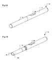
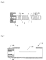
- a knock-type propelling container according to a first embodiment of the present invention.
- a reference sign 10 denotes the knock-type propelling container.
- the knock-type propelling container 10 includes a longitudinal body 12 to be held by a user, and a cap 14 detachably mounted with respect to the body 12.
- a medium M which is an object to be propelled by the knock-type propelling container 10 is stored in an interior of the body 12.
- the medium M there may be employed any medium in a voluntary form such as solid, liquid, or gel. While a cosmetic medium for an eyeliner, for example, is employed in this embodiment, the medium which is to be propelled by this embodiment is not limited to such a medium and, as the medium to be propelled by this embodiment, there may be employed media which are used in the fields of writing, correcting, medical treatment (including dental surgery), and industry.
- the medium M is adapted to be capable of being propelled from a tip end opening 12a which is formed in a tip end of the body 12.
- the body 12 may be assembled from several parts.
- the cap 14 is mounted on the body 12 so as to cover the tip end opening 12a.
- the body 12 has a lateral opening 12b formed in a side surface thereof.
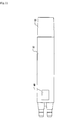
- a knock member 20 to be operated by the user is provided in the lateral opening 12b.
- the knock member 20 is adapted to be reciprocatably moved between inward and outward positions relative to the body 12 in a direction perpendicular to a forward/rearward direction of the body 12.
- the knock member 20 is formed substantially into a U-shape in cross-section. As shown in Fig. 5 , both side portions of the knock member 20 are notched in lower ends thereof, to thereby form plural cam surfaces 20a. Moreover, outer surfaces of the both side portions of the knock member 20 are provided with ribs 20b for preventing the knock member 20 from coming out of the lateral opening 12b of the body 12.
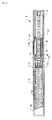
- a piston 22 and a piston rod 24 are provided in the body 12 so as be slidable in a forward/rearward direction.
- the piston 22 is adapted to be capable of thrusting the medium M toward the tip end opening 12a.
- the piston rod 24 is connected to a rear end of the piston 12 and extends in the forward/rearward direction.
- the piston 22 and the piston rod 24 form a propelling member.
- the piston rod 24 constitutes a forward/rearward extending prolongation portion of the propelling member.
- the piston rod 24 has a series of circular truncated cone-shaped portions 24a formed on an outer peripheral surface thereof and continued in the forward/rearward direction, in which step portions 24b formed by bottom surfaces of the circular truncated cone-shaped portions 24a, and taper portions 24c formed by slanted surfaces of the circular truncated cone-shaped portions 24a are alternately repeated.
- Engaging-stop portions 24d are defined by the step portions 24b and the taper portions 24c.
- a detent cylinder 26 and a thrusting cylinder 28 which covert radially inward movement of the knock member 20 relative to the body 12 (which is effected by knocking the knock member 20) into forward movement of the propelling member comprising the piston 20 and the piston rod 24 and allow the medium to be quantitatively propelled are provided in the body 12.
- the detent cylinder 26 has a notch portion 26a formed in a portion thereof which is positionally aligned with the lateral opening 12b of the body 12. Moreover, the detent cylinder 26 has a pair of detent pawls 26b provided at a tip end thereof and stoppingly engageable with the engaging-stop portions 24d of the piston rod 24. Each of the detent pawls 26b is formed at a tip end of an elastic piece portion interposed between slits formed by cutting-in the tip end of the detent cylinder 26, and is adapted to be elastically deformable in a radial direction.
- the engaging-stop portions 24d of the piston rod 24 can be moved forward while slipping relative to the detent pawls 26b but cannot slip rearward and is adapted to be maintained in the engagement state with the detent pawls 26b.
- the detent pawls 26b are adapted to be slippable rearward relative to the engaging-stop portions 24d.
- the thrusting cylinder 28 has a plurality of cam protrusions 28a provided on an outer peripheral surface thereof so as to be opposed to the cam surfaces 20a of the knock member 20.
- Cam surfaces 28b of the cam protrusions 28a are adapted to be slidingly contactable with the cam surfaces 20a of the knock member 20.
- the thrusting cylinder 28 has a pair of thrusting pawls 28c provided at side portions thereof and adapted to be stoppingly engageable with the engaging-stop portions 24d of the piston rod 24.
- Each of the thrusting pawls 28c is formed at a tip end of an elastic piece portion surrounded by three slits formed by cutting-in a peripheral surface of the thrusting cylinder 28, and is adapted to be elastically deformable in the radial direction.
- the thrusting pawls 28c can be moved rearward while being slid relative to the engaging-stop portions 24d of the piston rod 24 but cannot be slid forward and is adapted to be maintained in the engagement state with the engaging-stop portions 24d.
- a return spring 29 is arranged between an inner step surface of the detent cylinder 26 and a flange portion of the thrusting cylinder 28 and always biases the detent cylinder 26 and the thrusting cylinder 28 in a direction in which they are spaced away from each other.
- the detent cylinder 26 is pressedly applied by the return spring 29 onto a taper surface 12c formed around an inner surface of the body 12, whereby the detent cylinder 26 is always fixed to the body 12.
- the thrusting cylinder 28 is always biased in the rearward direction by the return spring 29 and adapted to be movable forward and rearward in the body 12 and the detent cylinder 26.
- a rear end of the body 12 is closed by a tail plug 13.
- the cap 14 is first detached from the body 12.
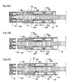
- the knock member 20 is knocked by the user ( Figs. 9A and 10A ).
- the cam surfaces 20a of the knock member 20 are slidingly contacted with the cam surfaces 28b of the thrusting cylinder 28, whereby the knock member 20 thrusts the thrusting cylinder 28 in the forward direction.
- the thrusting pawls 28c of the thrusting cylinder 28 are engaged with the engaging-stop portions 24d of the piston rod 24, so that the piston rod 24 and the piston 22 are moved forward according to the forward movement of the thrusting cylinder 28 ( Figs.
- the thrusting cylinder 28 tends to be returned in the rearward direction by the biasing force of the return spring 29 and the knock member 20 is thrustedly retuned outward of the body 12.
- the engaging-stop portions 24d of the piston rod 24 are stoppingly engaged by the detent pawls 26b of the detent cylinder 26 and rearward returning movement of the piston rod 24 is prevented.
- the thrusting pawls 28c of the thrusting cylinder 28 slip relative to the engaging-stop portions 24d of the piston rod 24, so that the thrusting cylinder 28 is rearward moved relative to the piston rod 24 ( Figs. 9C and 10C ).
- the piston rod 24 is adapted to be moved forward by an amount equivalent to a multiple of repeated pitches of the engaging-stop portions 24d, and the piston rod 24 is then maintained at a position to which the piston rod 24 has been moved, so that it is possible to quantitatively propel the medium M.
- a forward moving amount of the thrusting cylinder 28 movable forward by the one-time knocking operation of the knock member 20 is limited, so that a propelled amount of the medium M which is equivalent to the forward moving amount of the piston rod 24 can be always made equal to or less than a fixed amount.
- the pushed amount of the knock member 20 may be set to a predetermined extent.
- the piston rod 24 can be always moved forward by a moving amount that is equivalent to one pitch or fixed pitches of the engaging-stop portions 24d.
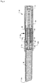
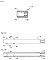
- a knock-type propelling container according to a second embodiment of the present invention.
- a reference sign 30 denotes the knock-type propelling container according to the second embodiment of the present invention.
- the knock-type propelling container 30 includes a longitudinal body 32 to be held by the user.
- Two storage chambers 32d, 32d are defined in the interior of the body 32.
- Media M1, M2 that are objects to be propelled by the knock-type propelling container 30 are stored in the storage chambers 32d, 32d.
- one M1 of media different from each other can be stored in one of the storage chambers 32d, 32d and the other M2 of the media can be stored in the other of the storage chambers 32d, 32d.
- the one M1 of the media which is stored in the one of the storage chambers 32d, 32d can be propelled from a tip end opening 32a formed in a tip end of the one of the storage chambers 32d, 32d, and the other M2 of the media which is stored in the other of the storage chambers 32d, 32d can be propelled from a tip end opening 32a formed in a tip end of the other of the storage chambers 32d, 32d.
- the media M1, M2 which are different from each other and propelled out of the container 30 can be mixed with each other outside the container 30.
- a drive chamber 32e is defined between the two storage chambers 32d, 32d in the body 32 so as to be arranged in parallel to the storage chambers 32d, 32d.
- the body 32 may be assembled from several parts.
- the body 32 has a lateral opening 32b formed in a side surface of a tip end portion thereof.
- a knock member 40 to be knocked by the user is provided in the lateral opening 32b.
- the knock member 40 is adapted to be reciprocatably moved between inward and outward positions relative to the body 32 in a direction perpendicular to a forward/rearward direction of the body 32.
- the knock member 40 is formed substantially into a U-shape in cross-section. As shown in Fig. 14 , both side portions of the knock member 40 are notched in lower ends thereof, to thereby form plural cam surfaces 40a. Moreover, the knock member 40 are provided on outer surfaces of forward and rearward end portions thereof with ribs 40b for preventing the knock member 40 from coming out of the lateral opening 32b of the body 32.
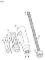
- a forward/rearward slidable propelling-member 42 which can propel the media M1, M2 toward the tip end openings 32a, 32a is housed in the body 32.
- the propelling member 42 includes pistons 43 provided correspondingly to the storage chambers 32d of the body 32, and a piston rod 44 provided correspondingly to the drive chamber 32e of the body 32. Rear end portions of the two pistons 43 are interconnected by a connection portion 43a.
- the piston rod 44 is extended forward from a center of the connection portion 43a and constitutes a forward/rearward extending prolongation portion of the propelling member 42.
- each of the pistons 43 has an annular recess portion 43b formed in a tip end portion thereof.
- An O-ring 45 for sealing is fitted in the annular recess portion 43b of the piston 43, so that the piston 43 is adapted to be slidable in the corresponding storage chamber 32d while maintaining a sealing property with respect to the storage chamber 32d.
- an outer peripheral surface of the piston rod 44 has a series of circular truncated cone-shaped portions 44a continued in the forward/rearward direction, in which step portions 44b formed by bottom surfaces of the circular truncated cone-shaped portions 44a, and taper portions 44c formed by slanted surfaces of the circular truncated cone-shaped portions 44a are alternately repeated.
- engaging-stop portions 44d are defined by the step portions 44b and the taper portions 44c.
- the series of circular truncated cone-shaped portions 44a is partially cut out.
- the reason that the series of circular truncated cone-shaped portions 44a is partially cut out is that, for example, when positions of respective components of the knock-type propelling container 30 are required to be adjusted at the time of assembling the knock-type propelling container 30, the piston rod 44 can be easily drawn out from a detent cylinder 46 and a thrusting cylinder 48 which will be discussed hereinafter.
- the detent cylinder 46 and the thrusting cylinder 48 which convert radially inward movement of the knock member 40 relative to the body 32 (which is effected by knocking the knock member 40) into forward movement of the propelling member 42 and allow the media to be quantitatively propelled are provided.
- the detent cylinder 46 has grooves 46a which engagedly receive protrusions 32f ( Fig. 13 ) formed on an inner peripheral surface of the body 32. By engagement between the grooves 46a and the protrusions 32f, the detent cylinder 46 is fixedly arranged in the body 32 in the forward/rearward direction.
- the detent cylinder 46 has a pair of detent pawls 46b provided in an interior thereof and stoppingly engageable with the engaging-stop portions 44d of the piston rod 44.
- Each of the detent pawls 46b is formed at a tip end of an elastic piece portion extending to the interior of the detent cylinder 46 from a rear end of the detent cylinder 46 and is adapted to be elastically deformable in the radial direction.
- the engaging-stop portions 44d of the piston rod 44 can be moved forward while slipping relative to the detent pawls 46b of the detent cylinder 46 but cannot slip rearward and is adapted to be maintained in the engagement state with the detent pawls 46b.
- the detent pawls 46b are adapted to be rearward slippable relative to the engaging-stop portions 44d of the piston rod 44.
- the thrusting cylinder 48 has plural cam protrusions 48a formed on an outer peripheral surface thereof. Cam surfaces 48b of the cam protrusions 48a are opposed to the cam surfaces 40a of the knock member 40 and adapted to be slidingly contactable with the cam surfaces 40a of the knock member 40. Moreover, the thrusting cylinder 48 is provided at a rear side portion thereof with a pair of thrusting pawls 48c which are stoppingly engageable with the engaging-stop portions 44d of the piston rod 44. Each of the thrusting pawls 48c is formed at a tip end of an elastic piece portion surrounded by three slits formed by cutting-in the peripheral surface of the thrusting cylinder 48, and is elastically deformable in the radial direction. The thrusting pawls 48c can be moved rearward while slipping relative to the engaging-stop portions 44d of the piston rod 44 but cannot slip forward and is adapted to be maintained in the engagement state with the engaging-stop portions 44d of the piston rod 44.
- a return spring 50 is provided between a tip end of the thrusting cylinder 48 and a tip end surface of the drive chamber 32e.
- the thrusting cylinder 48 is always biased rearward by the return spring 50 and is adapted to be movable forward and rearward in the drive chamber 32e.
- a rear end of the body 32 is closed by a tail plug 52.
- the knock-type propelling container 30 constructed as discussed above can be operated in the same manner as the knock-type propelling container 10 according to the first embodiment of the present invention is done. Namely, in a case where the media M1, M2 are intended to be propelled out of the body 32, when the knock member 40 is knocked by the user, the knock member 40 is pushed into the body 32 and the cam surfaces 40a of the knock member 40 are slidingly contacted with the cam surfaces 48b of the thrusting cylinder 48, whereby the knock member 40 causes the thrusting cylinder 48 to be thrust forward.
- the thrusting pawls 48c of the thrusting cylinder 48 are engaged with the engaging-stop portions 44d of the piston rod 44, so that the piston rod 44 and the pistons 43 are moved forward according to the forward movement of the thrusting cylinder 48, to thereby propel the media M1, M2 from the tip end openings 32a of the body 32.
- the engaging-stop portions 44d of the piston rod 44 slip relative to the detent pawls 46b of the detent cylinder 46, so that the piston rod 44 is forward moved relative to the detent cylinder 46.
- the thrusting cylinder 48 tends to be returned in the rearward direction by the biasing force of the return spring 50 and the knock member 40 is thrustedly retuned outward of the body 32.
- the engaging-stop portions 44d of the piston rod 44 are stoppingly engaged by the detent pawls 46b of the detent cylinder 46 and the rearward returning movement of the piston rod 44 and pistons 43 is prevented.
- the thrusting pawls 48c of the thrusting cylinder 48 slip relative to the engaging-stop portions 44d of the piston rod 44, so that the thrusting cylinder 48 is rearward moved relative to the piston rod 44.
- the piston rod 44 is adapted to be moved forward by an amount equivalent to a multiple of repeated pitches of the engaging-stop portions 44d, and the piston rod 44 is then maintained at a position to which the piston rod 44 has been advanced, so that it is possible to quantitatively propel the media M1, M2.
- a forward moving amount of the thrusting cylinder 48 movable forward by the one-time knocking operation of the knock member 40 is limited, so that propelled amounts of the media M1, M2 which are equivalent to the forward moving amount of the piston rod 44 can be always made equal to or less than fixed amounts.
- the knocking amount of the knock member 40 may be limited to a predetermined extent.
- the piston rod 44 can be always moved forward by a moving amount that is equivalent to one pitch or fixed pitches of the engaging-stop portions 44d.
- a ratio of the sectional areas of the storage chambers 32d, 32d and a ratio of the sectional areas of the pistons 43 may be each set to a ratio other than a ratio of 1, whereby supply ratios of the media M1, M2 can be varied.
- the knock-type propelling containers 10, 30 are structured as side knock-type propelling containers in which the knock members 20, 40 are provided in the lateral openings 12b, 32b of the bodies 12, 32, so that the user can carry out the knocking operation of the knock members 20, 40 without re-holding the bodies 12, 32.
- knock-type propelling containers 10, 30 to which the present invention may be applied are not limited to such side knock-type propelling containers.
- the present invention may be applied to so-called rear end knock-type propelling containers.
- the knock member is arranged at a rear end of the body and integrally connected to the thrusting cylinder (for example, the knock member and the thrusting cylinder may be structured as a one-piece member comprising the knock member and the thrusting cylinder, or the knock member and the thrusting cylinder which are formed separately from each other may be integrally connected to each other), and the thrusting cylinder is always biased in the rearward direction by the return spring.
- the thrusting cylinder is adapted to be moved forward together with the knock member.
- the components other than the knock member and the thrusting cylinder are adapted to be operated in the same manner as those of the first and second embodiments are done, whereby the medium or the media can be propelled out of the body.
- the piston rod detention mechanism which may be employed according to the present invention is not limited to such a piston rod detention mechanism.
- detent cylinders for the piston rods there may be employed rubber packings.
- the rubber packings are disposed so as to be contactingly engaged with the piston rods 24, 44 and the detention of the piston rods 24, 44 can be accomplished by frictional forces which are produced between the rubber packings and the piston rods 24, 44.
- any voluntary engagement fashion between the detent cylinders and the piston rods 24, 44 or pistons 22, 43 for example, engagement by magnetic force
- the detention of the piston rods 24, 44 and pistons 22, 43 can be accomplished.
- a movement conversion mechanism which may be employed according to the present invention is not limited to such a movement conversion mechanism and the conversion of the movement of the knock members 20, 40 into the forward movement of the thrusting cylinders 28, 48 may be performed by using linkage mechanisms, gear mechanisms or other voluntary mechanisms.
- elements which are each assembled from several components in the above-mentioned embodiments may be each composed of a single component, and elements which are each composed of a single component in the above-mentioned embodiments may be each assembled from several components.
Landscapes
- Engineering & Computer Science (AREA)
- Mechanical Engineering (AREA)
- Coating Apparatus (AREA)
- Mechanical Pencils And Projecting And Retracting Systems Therefor, And Multi-System Writing Instruments (AREA)
- Containers And Packaging Bodies Having A Special Means To Remove Contents (AREA)
- Pens And Brushes (AREA)
Claims (9)
- Knopfdruck-Vortriebbehälter (10), der Folgendes umfasst:einen Körper (12), in dem ein Medium (M) aufbewahrt wird und der eine Spitzenendöffnung (12a) zum Gestatten, dass das Medium (M) daraus ausgegeben wird, aufweist;ein Vortriebglied (22, 24), das dahingehend in dem Körper (12) angeordnet ist, in eine Vorwärts-/Rückwärtsrichtung des Körpers (12) geschoben zu werden, und dazu in der Lage ist, das Medium (M) zu der Spitzenendöffnung (12a) vorzutreiben;wobei das Vortriebglied (22, 24) mit einem sich vorwärts/rückwärts erstreckenden Verlängerungsabschnitt (24) versehen ist, der eine Reihe von Eingriffsanschlagabschnitten (24d) aufweist, die in festgelegten Abständen in der Vorwärts-/Rückwärtsrichtung angeordnet sind;ein Knopfdruckglied (20), das dahingehend in einer in einem Seitenabschnitt des Körpers (12) ausgebildeten lateralen Öffnung (12b) vorgesehen ist, bezüglich des Körpers (12) hin- und herbewegt zu werden;einen Sperrzylinder (26), der fest in dem Körper (12) in der Vorwärts-/Rückwärtsrichtung angeordnet ist und dahingehend mit dem Vortriebglied (22, 24) in Eingriff steht, bezüglich des Vortriebglieds (22, 24) nach hinten schiebbar zu sein;wobei der Sperrzylinder (26) durch eine Rückstellfeder (29) auf eine um eine Innenfläche des Körpers (12) herum ausgebildete Konusfläche (12c) gedrückt wird;einen Schubzylinder (28), der in dem Körper (12) angeordnet und durch die Rückstellfeder (29), die zwischen einer inneren Stufenfläche des Sperrzylinders (26) und einem Flanschabschnitt des Schubzylinders (28) angeordnet ist und die den Sperrzylinder (26) und den Schubzylinder (28) stets in einer Richtung, in der sie voneinander beabstandet sind, vorspannt, stets in eine Rückwärtsrichtung vorgespannt ist;wobei der Schubzylinder (28) dazu ausgeführt ist, in dem Körper (12) und dem Sperrzylinder (26) nach vorne und nach hinten beweglich zu sein, wobei der Schubzylinder (28) dazu ausgeführt ist, durch Drücken des Knopfdruckglieds (20) nach vorne bewegt und dahingehend mit den Eingriffanschlagabschnitten (24d) des Vortriebglieds (22, 24) in Anschlageingriff gebracht zu werden, bezüglich der Eingriffanschlagabschnitte (24d) des Vortriebglieds (22, 24) nach hinten schiebbar zu sein;wobei das Knopfdruckglied (20) dazu ausgeführt ist, in einer senkrecht zu der Vorwärts-/Rückwärtsrichtung des Körpers (12) verlaufenden Richtung hin- und herbewegt zu werden, wobei das Knopfdruckglied (20) mit ersten Nockenflächen (20a) ausgebildet ist, wobei der Schubzylinder (28) mit zweiten Nockenflächen (28b) ausgebildet ist, die bezüglich der ersten Nockenfläche (20a) verschiebbar sind, und wenn das Knopfdruckglied (20) gedrückt wird, wirken die ersten Nockenflächen (20a) und die zweiten Nockenflächen (28b) dahingehend zusammen, zu bewirken, dass der Schubzylinder (28) nach vorne bewegt wird.
- Knopfdruck-Vortriebbehälter (10) nach Anspruch 1, wobei der Verlängerungsabschnitt (24) mehrere fortlaufend ausgebildete kreisförmige kegelstumpfförmige Abschnitte (24a) umfasst, die jeweils einen der Eingriffanschlagabschnitte (24d) bilden.
- Knopfdruck-Vortriebbehälter (10) nach Anspruch 1 oder 2, wobei der Schubzylinder (28) mit einer Schubklinke (28c) versehen ist, die an einem Spitzenende eines Abschnitts aus einem elastischen Stück, der in einer radialen Richtung bezüglich des Verlängerungsabschnitts (24) verformbar ist, ausgebildet ist und dazu ausgeführt ist, mit den Eingriffanschlagabschnitten (24d) in Anschlageingriff gebracht zu werden.
- Knopfdruck-Vortriebbehälter (10) nach einem der Ansprüche 1-3, wobei der Sperrzylinder (26) mit einer Sperrklinke (26b) versehen ist, die an einem Spitzenende eines Abschnitts aus einem elastischen Stück, der in einer radialen Richtung bezüglich des Verlängerungsabschnitts (24) verformbar ist, ausgebildet ist und dazu ausgeführt ist, mit den Eingriffanschlagabschnitten (24d) in Anschlageingriff gebracht zu werden.
- Knopfdruck-Vortriebbehälter (30), der Folgendes umfasst:einen Körper (32), in dem ein Medium (M1, M2) in zwei darin definierten Aufbewahrungskammern (32d) aufbewahrt wird und der eine in einem Spitzenende jeder Aufbewahrungskammer (32d) ausgebildete Spitzenendöffnung (32a) zum Gestatten, dass das Medium (M1, M2) daraus ausgegeben wird, aufweist;eine Antriebskammer (32e), die zwischen den Aufbewahrungskammern (32d) in dem Körper (32) so definiert wird, dass sie parallel zu den Aufbewahrungskammern (32d) angeordnet ist;ein Vortriebglied (42, 43, 44), das dahingehend in dem Körper (32) angeordnet ist, in eine Vorwärts-/Rückwärtsrichtung des Körpers (32) geschoben zu werden, und dazu in der Lage ist, das Medium (M1, M2) zu den Spitzenendöffnungen (32a) vorzutreiben;wobei das Vortriebglied (42, 43, 44) mit einem sich vorwärts/rückwärts erstreckenden Verlängerungsabschnitt (44) versehen ist, der eine Reihe von Eingriffsanschlagabschnitten (44d) aufweist, die in festgelegten Abständen in der Vorwärts-/Rückwärtsrichtung angeordnet sind;ein Knopfdruckglied (40), das dahingehend in einer in einem Seitenabschnitt des Körpers (32) ausgebildeten lateralen Öffnung (32b) vorgesehen ist, bezüglich des Körpers (32) hin- und herbewegt zu werden;einen Schubzylinder (48), der in dem Körper (32) angeordnet und dazu ausgeführt ist, in der Antriebskammer (32e) nach vorne und nach hinten beweglich zu sein, wobei der Schubzylinder (48) durch eine Rückstellfeder (50), die zwischen einem Spitzenende des Schubzylinders (48) und einer Spitzenendfläche der Antriebskammer (32e) angeordnet ist, stets nach hinten vorgespannt wird;wobei der Schubzylinder (48) dazu ausgeführt ist, durch Drücken des Knopfdruckglieds (40) nach vorne bewegt und dahingehend mit den Eingriffanschlagabschnitten (44d) des Vortriebglieds (42, 43, 44) in Anschlageingriff gebracht zu werden, bezüglich der Eingriffanschlagabschnitte (44d) des Vortriebglieds (42, 43, 44) nach hinten schiebbar zu sein; undeinen Sperrzylinder (46), der fest in dem Körper (32) in der Vorwärts-/Rückwärtsrichtung angeordnet ist und dahingehend mit dem Vortriebglied (42, 43, 44) in Eingriff steht, bezüglich des Vortriebglieds (42, 43, 44) nach hinten schiebbar zu sein;wobei das Knopfdruckglied (40) dazu ausgeführt ist, in einer senkrecht zu der Vorwärts-/Rückwärtsrichtung des Körpers (32) verlaufenden Richtung hin- und herbewegt zu werden, wobei das Knopfdruckglied (40) mit ersten Nockenflächen (40a) ausgebildet ist, wobei der Schubzylinder (48) mit zweiten Nockenflächen (48b) ausgebildet ist, die bezüglich der ersten Nockenflächen (40a) verschiebbar sind, und wenn das Knopfdruckglied (40) gedrückt wird, wirken die ersten Nockenflächen (40a) und die zweiten Nockenflächen (48b) dahingehend zusammen, zu bewirken, dass der Schubzylinder (48) nach vorne bewegt wird.
- Knopfdruck-Vortriebbehälter (30) nach Anspruch 5, wobei der Verlängerungsabschnitt (44) mehrere fortlaufend ausgebildete kreisförmige kegelstumpfförmige Abschnitte (44a) umfasst, die jeweils einen der Eingriffanschlagabschnitte (44d) bilden.
- Knopfdruck-Vortriebbehälter (30) nach Anspruch 5 oder 6, wobei der Schubzylinder (48) mit einer Schubklinke (48c) versehen ist, die an einem Spitzenende eines Abschnitts aus einem elastischen Stück, der in einer radialen Richtung bezüglich des Verlängerungsabschnitts (44) verformbar ist, ausgebildet ist und dazu ausgeführt ist, mit den Eingriffanschlagabschnitten (44d) in Anschlageingriff gebracht zu werden.
- Knopfdruck-Vortriebbehälter (30) nach einem der Ansprüche 5-7, wobei der Sperrzylinder (46) mit einer Sperrklinke (46b) versehen ist, die an einem Spitzenende eines Abschnitts aus einem elastischen Stück, der in einer radialen Richtung bezüglich des Verlängerungsabschnitts (44) verformbar ist, ausgebildet ist und dazu ausgeführt ist, mit den Eingriffanschlagabschnitten (44d) in Anschlageingriff gebracht zu werden.
- Knopfdruck-Vortriebbehälter (30) nach einem der Ansprüche 5-8, wobei das Vortriebglied (42, 43, 44) mehrere Kolben (43) aufweist, die entsprechend den mehreren Spitzenendöffnungen (32a) vorgesehen sind und das Medium (M1, M2) zu den Spitzenendöffnungen (32a) schieben, und der Verlängerungsabschnitt (44) parallel zu den mehreren Kolben (43) angeordnet ist.
Applications Claiming Priority (2)
| Application Number | Priority Date | Filing Date | Title |
|---|---|---|---|
| JP2010180293 | 2010-08-11 | ||
| PCT/JP2011/068299 WO2012020803A1 (ja) | 2010-08-11 | 2011-08-10 | ノック式繰出し容器 |
Publications (3)
| Publication Number | Publication Date |
|---|---|
| EP2604142A1 EP2604142A1 (de) | 2013-06-19 |
| EP2604142A4 EP2604142A4 (de) | 2017-12-06 |
| EP2604142B1 true EP2604142B1 (de) | 2020-04-08 |
Family
ID=45567765
Family Applications (1)
| Application Number | Title | Priority Date | Filing Date |
|---|---|---|---|
| EP11816467.2A Active EP2604142B1 (de) | 2010-08-11 | 2011-08-10 | Knopfdruck-ausgabebehälter |
Country Status (6)
| Country | Link |
|---|---|
| US (1) | US9114922B2 (de) |
| EP (1) | EP2604142B1 (de) |
| JP (1) | JP5555774B2 (de) |
| KR (1) | KR101869991B1 (de) |
| CN (1) | CN103079428B (de) |
| WO (1) | WO2012020803A1 (de) |
Families Citing this family (14)
| Publication number | Priority date | Publication date | Assignee | Title |
|---|---|---|---|---|
| JP6318344B2 (ja) * | 2014-03-26 | 2018-05-09 | 株式会社トキワ | カートリッジ式内容物押出容器 |
| US20160058155A1 (en) | 2014-09-02 | 2016-03-03 | HCT Group Holdings Limited | Container with dispensing tip |
| WO2016044266A1 (en) | 2014-09-15 | 2016-03-24 | HCT Group Holdings Limited | Container with collapsible applicator |
| US9707052B2 (en) * | 2015-01-29 | 2017-07-18 | Bryan Tapocik | Mechanical pen with improvements for pen removably retaining single use capsule containing tooth whitening compounds, dental bonding compounds and adhesives and removably retaining disposable tooth whitening applicators, disposable dental bonding compound applicators and disposable adhesive applicators |
| US9993059B2 (en) | 2015-07-10 | 2018-06-12 | HCT Group Holdings Limited | Roller applicator |
| USD818641S1 (en) | 2016-03-16 | 2018-05-22 | HCT Group Holdings Limited | Cosmetics applicator with cap |
| CN107713285B (zh) * | 2016-08-10 | 2020-01-21 | 阿蓓亚塑料实业(上海)有限公司 | 条状包装 |
| KR101881760B1 (ko) | 2016-10-21 | 2018-07-25 | 석종완 | 펜타입 화장품 용기 |
| US10272714B2 (en) | 2016-12-06 | 2019-04-30 | Sanford L.P. | Anti-rotation extendable eraser mechanism |
| KR102053019B1 (ko) | 2018-01-31 | 2019-12-09 | 주식회사 라인프러스 | 펜 형 화장품 용기 |
| US10980332B2 (en) * | 2018-03-29 | 2021-04-20 | Mitsubishi Pencil Company, Limited | Cosmetic applicator |
| KR200487135Y1 (ko) * | 2018-06-27 | 2018-09-10 | 이성환 | 선스틱 용기 |
| CN108968294B (zh) * | 2018-08-29 | 2021-08-06 | 浙江章华保健美发实业有限公司 | 一种可调式搭配组合型化妆笔的使用方法 |
| JP7403178B2 (ja) * | 2020-01-22 | 2023-12-22 | 巣山技研有限会社 | 髪・毛束ね具 |
Family Cites Families (37)
| Publication number | Priority date | Publication date | Assignee | Title |
|---|---|---|---|---|
| US2541949A (en) * | 1947-05-01 | 1951-02-13 | Warren E Thacker | Rouge dispenser and applicator with ratchet operated force feed mechanism |
| JPS5222778U (de) * | 1975-08-05 | 1977-02-17 | ||
| JPS5222778A (en) | 1975-08-13 | 1977-02-21 | Hitachi Ltd | Vacuum valve circuit breaker |
| ATE19203T1 (de) * | 1981-11-12 | 1986-05-15 | John Joseph Jacklich | Zahnspritze. |
| DE3316922A1 (de) * | 1983-05-09 | 1984-11-15 | Henkel KGaA, 4000 Düsseldorf | Vorrichtung zum abgeben von in vorgegebenem verhaeltnis zu mischenden stoffen |
| JPS6086484A (ja) | 1983-10-18 | 1985-05-16 | 株式会社東芝 | 核融合装置の第一壁 |
| JPS6086484U (ja) * | 1983-11-17 | 1985-06-14 | 株式会社 サクラクレパス | 塗布具の塗布液調節装置 |
| US4690306A (en) * | 1985-08-12 | 1987-09-01 | Ciba-Geigy Corporation | Dispensing device for storing and applying at least one liquid or pasty substance |
| US4659327A (en) * | 1985-11-26 | 1987-04-21 | Dentsply Research & Development Corp. | Multiple dosage syringe |
| JPS648317A (en) | 1987-06-27 | 1989-01-12 | Fuji Heavy Ind Ltd | Intake mechanism of engine equipped with supercharger |
| JPS648317U (de) * | 1987-07-02 | 1989-01-18 | ||
| FR2642623B1 (fr) * | 1989-02-08 | 1991-05-03 | Oreal | Distributeur comportant un piston translatable |
| US5584815A (en) * | 1993-04-02 | 1996-12-17 | Eli Lilly And Company | Multi-cartridge medication injection device |
| TW301975U (en) * | 1995-11-20 | 1997-04-01 | Kotobuki & Co Ltd | Dispenser for selectively extending and retracting a substantially stick-shaped object and writing instrument with the dispenser |
| JP3553297B2 (ja) | 1995-11-20 | 2004-08-11 | 株式会社壽 | 棒状物繰り出し容器付き筆記具 |
| KR200220243Y1 (ko) * | 2000-09-14 | 2001-04-16 | 이종철 | 겔상 립스틱 용기 |
| KR200230179Y1 (ko) * | 2000-12-30 | 2001-07-03 | 이종철 | 겔상 립스틱 용기 |
| GB2374014A (en) * | 2001-04-02 | 2002-10-09 | Cambridge Consultants | Biological sealant storage and dispensing system |
| DE10232410B4 (de) * | 2002-07-17 | 2006-12-21 | Tecpharma Licensing Ag | Verabreichungsgerät mit Dosisanzeige |
| US6729785B2 (en) * | 2002-08-06 | 2004-05-04 | Rose Art Industries, Inc. | Method and device for advancing a lead and an eraser in a mechanical pencil and for advancing a pen and an eraser in a pen |
| JP4412935B2 (ja) | 2003-07-31 | 2010-02-10 | 株式会社パイロットコーポレーション | 筆記具の軸筒 |
| FR2861330B1 (fr) * | 2003-10-22 | 2006-02-03 | Bic Soc | Instrument d'ecriture a bouton lateral |
| JP4468002B2 (ja) | 2004-02-02 | 2010-05-26 | 壽印刷紙工株式会社 | サイドノック式繰出し機構 |
| JP2005246871A (ja) | 2004-03-05 | 2005-09-15 | Kotobuki Insatsu Shiko Kk | 複合軸体保持具 |
| KR200362352Y1 (ko) * | 2004-06-19 | 2004-09-16 | 이종철 | 겔상 파운데이션 용기 |
| ES2305850T3 (es) * | 2004-06-29 | 2008-11-01 | Rnd Group Llc | Envase de cosmetico labial. |
| KR200391579Y1 (ko) * | 2005-04-08 | 2005-08-08 | 강성일 | 여러 종류의 고점도 내용물의 정량 토출 화장품용기 |
| JP4607746B2 (ja) * | 2005-11-28 | 2011-01-05 | 株式会社トキワ | 内容物押出容器 |
| KR200438562Y1 (ko) * | 2007-02-01 | 2008-02-22 | 강성일 | 펜슬형 화장품용기 |
| JP2008246079A (ja) * | 2007-03-30 | 2008-10-16 | Tokiwa Corp | 塗布材押出容器及び塗布材押出容器の成形方法 |
| US8540124B2 (en) * | 2007-10-11 | 2013-09-24 | Lucas Packaging Group, Inc. | Dispensing pen |
| WO2009125868A1 (ja) * | 2008-04-11 | 2009-10-15 | 三菱鉛筆株式会社 | ノック式繰出容器 |
| JP5294789B2 (ja) | 2008-10-10 | 2013-09-18 | 三菱鉛筆株式会社 | ノック式繰出容器 |
| JP5263938B2 (ja) | 2008-04-25 | 2013-08-14 | 株式会社三谷バルブ | ノック式の内容物吐出機構およびこの内容物吐出機構を備えたノック式ディスペンサー |
| JP5280109B2 (ja) * | 2008-05-30 | 2013-09-04 | 株式会社壽 | サイドノック式液体繰出し装置 |
| US20090314808A1 (en) * | 2008-06-20 | 2009-12-24 | Leo Clifford Pires | Delivery system |
| DE112011103764B4 (de) * | 2010-11-15 | 2015-04-02 | Milwaukee Electric Tool Corp. | Elektrisch angetriebenes Ausgabewerkzeug |
-
2011
- 2011-08-10 US US13/816,207 patent/US9114922B2/en not_active Expired - Fee Related
- 2011-08-10 KR KR1020137003220A patent/KR101869991B1/ko not_active Expired - Fee Related
- 2011-08-10 EP EP11816467.2A patent/EP2604142B1/de active Active
- 2011-08-10 JP JP2012528704A patent/JP5555774B2/ja active Active
- 2011-08-10 CN CN201180039433.2A patent/CN103079428B/zh not_active Expired - Fee Related
- 2011-08-10 WO PCT/JP2011/068299 patent/WO2012020803A1/ja not_active Ceased
Non-Patent Citations (1)
| Title |
|---|
| None * |
Also Published As
| Publication number | Publication date |
|---|---|
| US20130134189A1 (en) | 2013-05-30 |
| JP5555774B2 (ja) | 2014-07-23 |
| JPWO2012020803A1 (ja) | 2013-10-28 |
| CN103079428A (zh) | 2013-05-01 |
| KR101869991B1 (ko) | 2018-06-22 |
| CN103079428B (zh) | 2015-07-29 |
| EP2604142A1 (de) | 2013-06-19 |
| KR20140045280A (ko) | 2014-04-16 |
| US9114922B2 (en) | 2015-08-25 |
| EP2604142A4 (de) | 2017-12-06 |
| WO2012020803A1 (ja) | 2012-02-16 |
Similar Documents
| Publication | Publication Date | Title |
|---|---|---|
| EP2604142B1 (de) | Knopfdruck-ausgabebehälter | |
| US4189065A (en) | Metering dispenser for high-viscosity compositions | |
| US10674802B2 (en) | Pen type cosmetics case | |
| JP7087370B2 (ja) | 長尺物繰り出し装置及びこれを備える筆記具 | |
| HUP0400186A2 (en) | Expression device for a cartridge comprising two chambers arranged concentrically to each other | |
| US20160176026A1 (en) | Manual screwdriver | |
| JP5374342B2 (ja) | 塗布材押出容器 | |
| US5364197A (en) | Cosmetic pencil with descending sheath | |
| JP2000262324A (ja) | ネジ棒繰出装置およびこの装置を用いたピストン式押出容器 | |
| JP4320362B1 (ja) | 粘性体収容器 | |
| US6499897B2 (en) | Container for stick type cosmetic material | |
| US9067233B2 (en) | Stick-shaped material propelling container | |
| CA3126797A1 (en) | One-hand operated multi-pencil | |
| CN114947343B (zh) | 涂布材料旋出容器 | |
| US20240315423A1 (en) | Cartridge core assembly and cosmetic container comprising cartridge core assembly | |
| JP7620317B2 (ja) | カートリッジ式化粧料押出容器 | |
| US10967667B2 (en) | Feeding pencil | |
| JP5297794B2 (ja) | 吐出容器 | |
| CN2761022Y (zh) | 一种化妆笔 | |
| WO2025005234A1 (ja) | 回転繰出容器 | |
| JP3297283B2 (ja) | 棒状媒体用容器 | |
| US11857058B2 (en) | Cosmetic container with scraping member | |
| JPH0543692Y2 (de) | ||
| JP3799433B2 (ja) | 液状化粧料注出容器 | |
| CN210329731U (zh) | 结合胶笔和眉笔的两用化妆笔 |
Legal Events
| Date | Code | Title | Description |
|---|---|---|---|
| PUAI | Public reference made under article 153(3) epc to a published international application that has entered the european phase |
Free format text: ORIGINAL CODE: 0009012 |
|
| 17P | Request for examination filed |
Effective date: 20130307 |
|
| AK | Designated contracting states |
Kind code of ref document: A1 Designated state(s): AL AT BE BG CH CY CZ DE DK EE ES FI FR GB GR HR HU IE IS IT LI LT LU LV MC MK MT NL NO PL PT RO RS SE SI SK SM TR |
|
| DAX | Request for extension of the european patent (deleted) | ||
| RA4 | Supplementary search report drawn up and despatched (corrected) |
Effective date: 20171107 |
|
| RIC1 | Information provided on ipc code assigned before grant |
Ipc: B43L 19/00 20060101ALI20171031BHEP Ipc: A45D 40/20 20060101AFI20171031BHEP Ipc: A45D 34/00 20060101ALI20171031BHEP Ipc: B65D 83/00 20060101ALI20171031BHEP Ipc: B43K 24/00 20060101ALI20171031BHEP Ipc: B43K 23/016 20060101ALI20171031BHEP |
|
| STAA | Information on the status of an ep patent application or granted ep patent |
Free format text: STATUS: EXAMINATION IS IN PROGRESS |
|
| 17Q | First examination report despatched |
Effective date: 20190121 |
|
| GRAP | Despatch of communication of intention to grant a patent |
Free format text: ORIGINAL CODE: EPIDOSNIGR1 |
|
| STAA | Information on the status of an ep patent application or granted ep patent |
Free format text: STATUS: GRANT OF PATENT IS INTENDED |
|
| INTG | Intention to grant announced |
Effective date: 20191125 |
|
| GRAS | Grant fee paid |
Free format text: ORIGINAL CODE: EPIDOSNIGR3 |
|
| GRAA | (expected) grant |
Free format text: ORIGINAL CODE: 0009210 |
|
| STAA | Information on the status of an ep patent application or granted ep patent |
Free format text: STATUS: THE PATENT HAS BEEN GRANTED |
|
| AK | Designated contracting states |
Kind code of ref document: B1 Designated state(s): AL AT BE BG CH CY CZ DE DK EE ES FI FR GB GR HR HU IE IS IT LI LT LU LV MC MK MT NL NO PL PT RO RS SE SI SK SM TR |
|
| REG | Reference to a national code |
Ref country code: GB Ref legal event code: FG4D |
|
| REG | Reference to a national code |
Ref country code: CH Ref legal event code: EP Ref country code: AT Ref legal event code: REF Ref document number: 1253175 Country of ref document: AT Kind code of ref document: T Effective date: 20200415 |
|
| REG | Reference to a national code |
Ref country code: DE Ref legal event code: R096 Ref document number: 602011066161 Country of ref document: DE |
|
| REG | Reference to a national code |
Ref country code: IE Ref legal event code: FG4D |
|
| REG | Reference to a national code |
Ref country code: NL Ref legal event code: MP Effective date: 20200408 |
|
| REG | Reference to a national code |
Ref country code: LT Ref legal event code: MG4D |
|
| PG25 | Lapsed in a contracting state [announced via postgrant information from national office to epo] |
Ref country code: PT Free format text: LAPSE BECAUSE OF FAILURE TO SUBMIT A TRANSLATION OF THE DESCRIPTION OR TO PAY THE FEE WITHIN THE PRESCRIBED TIME-LIMIT Effective date: 20200817 Ref country code: GR Free format text: LAPSE BECAUSE OF FAILURE TO SUBMIT A TRANSLATION OF THE DESCRIPTION OR TO PAY THE FEE WITHIN THE PRESCRIBED TIME-LIMIT Effective date: 20200709 Ref country code: FI Free format text: LAPSE BECAUSE OF FAILURE TO SUBMIT A TRANSLATION OF THE DESCRIPTION OR TO PAY THE FEE WITHIN THE PRESCRIBED TIME-LIMIT Effective date: 20200408 Ref country code: IS Free format text: LAPSE BECAUSE OF FAILURE TO SUBMIT A TRANSLATION OF THE DESCRIPTION OR TO PAY THE FEE WITHIN THE PRESCRIBED TIME-LIMIT Effective date: 20200808 Ref country code: SE Free format text: LAPSE BECAUSE OF FAILURE TO SUBMIT A TRANSLATION OF THE DESCRIPTION OR TO PAY THE FEE WITHIN THE PRESCRIBED TIME-LIMIT Effective date: 20200408 Ref country code: NO Free format text: LAPSE BECAUSE OF FAILURE TO SUBMIT A TRANSLATION OF THE DESCRIPTION OR TO PAY THE FEE WITHIN THE PRESCRIBED TIME-LIMIT Effective date: 20200708 Ref country code: LT Free format text: LAPSE BECAUSE OF FAILURE TO SUBMIT A TRANSLATION OF THE DESCRIPTION OR TO PAY THE FEE WITHIN THE PRESCRIBED TIME-LIMIT Effective date: 20200408 Ref country code: NL Free format text: LAPSE BECAUSE OF FAILURE TO SUBMIT A TRANSLATION OF THE DESCRIPTION OR TO PAY THE FEE WITHIN THE PRESCRIBED TIME-LIMIT Effective date: 20200408 |
|
| PGFP | Annual fee paid to national office [announced via postgrant information from national office to epo] |
Ref country code: DE Payment date: 20200819 Year of fee payment: 10 Ref country code: FR Payment date: 20200821 Year of fee payment: 10 |
|
| REG | Reference to a national code |
Ref country code: AT Ref legal event code: MK05 Ref document number: 1253175 Country of ref document: AT Kind code of ref document: T Effective date: 20200408 |
|
| PG25 | Lapsed in a contracting state [announced via postgrant information from national office to epo] |
Ref country code: BG Free format text: LAPSE BECAUSE OF FAILURE TO SUBMIT A TRANSLATION OF THE DESCRIPTION OR TO PAY THE FEE WITHIN THE PRESCRIBED TIME-LIMIT Effective date: 20200708 Ref country code: RS Free format text: LAPSE BECAUSE OF FAILURE TO SUBMIT A TRANSLATION OF THE DESCRIPTION OR TO PAY THE FEE WITHIN THE PRESCRIBED TIME-LIMIT Effective date: 20200408 Ref country code: HR Free format text: LAPSE BECAUSE OF FAILURE TO SUBMIT A TRANSLATION OF THE DESCRIPTION OR TO PAY THE FEE WITHIN THE PRESCRIBED TIME-LIMIT Effective date: 20200408 Ref country code: LV Free format text: LAPSE BECAUSE OF FAILURE TO SUBMIT A TRANSLATION OF THE DESCRIPTION OR TO PAY THE FEE WITHIN THE PRESCRIBED TIME-LIMIT Effective date: 20200408 |
|
| PG25 | Lapsed in a contracting state [announced via postgrant information from national office to epo] |
Ref country code: AL Free format text: LAPSE BECAUSE OF FAILURE TO SUBMIT A TRANSLATION OF THE DESCRIPTION OR TO PAY THE FEE WITHIN THE PRESCRIBED TIME-LIMIT Effective date: 20200408 |
|
| REG | Reference to a national code |
Ref country code: DE Ref legal event code: R097 Ref document number: 602011066161 Country of ref document: DE |
|
| PG25 | Lapsed in a contracting state [announced via postgrant information from national office to epo] |
Ref country code: ES Free format text: LAPSE BECAUSE OF FAILURE TO SUBMIT A TRANSLATION OF THE DESCRIPTION OR TO PAY THE FEE WITHIN THE PRESCRIBED TIME-LIMIT Effective date: 20200408 Ref country code: AT Free format text: LAPSE BECAUSE OF FAILURE TO SUBMIT A TRANSLATION OF THE DESCRIPTION OR TO PAY THE FEE WITHIN THE PRESCRIBED TIME-LIMIT Effective date: 20200408 Ref country code: DK Free format text: LAPSE BECAUSE OF FAILURE TO SUBMIT A TRANSLATION OF THE DESCRIPTION OR TO PAY THE FEE WITHIN THE PRESCRIBED TIME-LIMIT Effective date: 20200408 Ref country code: SM Free format text: LAPSE BECAUSE OF FAILURE TO SUBMIT A TRANSLATION OF THE DESCRIPTION OR TO PAY THE FEE WITHIN THE PRESCRIBED TIME-LIMIT Effective date: 20200408 Ref country code: IT Free format text: LAPSE BECAUSE OF FAILURE TO SUBMIT A TRANSLATION OF THE DESCRIPTION OR TO PAY THE FEE WITHIN THE PRESCRIBED TIME-LIMIT Effective date: 20200408 Ref country code: EE Free format text: LAPSE BECAUSE OF FAILURE TO SUBMIT A TRANSLATION OF THE DESCRIPTION OR TO PAY THE FEE WITHIN THE PRESCRIBED TIME-LIMIT Effective date: 20200408 Ref country code: CZ Free format text: LAPSE BECAUSE OF FAILURE TO SUBMIT A TRANSLATION OF THE DESCRIPTION OR TO PAY THE FEE WITHIN THE PRESCRIBED TIME-LIMIT Effective date: 20200408 Ref country code: RO Free format text: LAPSE BECAUSE OF FAILURE TO SUBMIT A TRANSLATION OF THE DESCRIPTION OR TO PAY THE FEE WITHIN THE PRESCRIBED TIME-LIMIT Effective date: 20200408 |
|
| PLBE | No opposition filed within time limit |
Free format text: ORIGINAL CODE: 0009261 |
|
| STAA | Information on the status of an ep patent application or granted ep patent |
Free format text: STATUS: NO OPPOSITION FILED WITHIN TIME LIMIT |
|
| PG25 | Lapsed in a contracting state [announced via postgrant information from national office to epo] |
Ref country code: PL Free format text: LAPSE BECAUSE OF FAILURE TO SUBMIT A TRANSLATION OF THE DESCRIPTION OR TO PAY THE FEE WITHIN THE PRESCRIBED TIME-LIMIT Effective date: 20200408 Ref country code: SK Free format text: LAPSE BECAUSE OF FAILURE TO SUBMIT A TRANSLATION OF THE DESCRIPTION OR TO PAY THE FEE WITHIN THE PRESCRIBED TIME-LIMIT Effective date: 20200408 |
|
| 26N | No opposition filed |
Effective date: 20210112 |
|
| PG25 | Lapsed in a contracting state [announced via postgrant information from national office to epo] |
Ref country code: MC Free format text: LAPSE BECAUSE OF FAILURE TO SUBMIT A TRANSLATION OF THE DESCRIPTION OR TO PAY THE FEE WITHIN THE PRESCRIBED TIME-LIMIT Effective date: 20200408 |
|
| REG | Reference to a national code |
Ref country code: CH Ref legal event code: PL |
|
| GBPC | Gb: european patent ceased through non-payment of renewal fee |
Effective date: 20200810 |
|
| PG25 | Lapsed in a contracting state [announced via postgrant information from national office to epo] |
Ref country code: CH Free format text: LAPSE BECAUSE OF NON-PAYMENT OF DUE FEES Effective date: 20200831 Ref country code: LI Free format text: LAPSE BECAUSE OF NON-PAYMENT OF DUE FEES Effective date: 20200831 Ref country code: LU Free format text: LAPSE BECAUSE OF NON-PAYMENT OF DUE FEES Effective date: 20200810 |
|
| REG | Reference to a national code |
Ref country code: BE Ref legal event code: MM Effective date: 20200831 |
|
| PG25 | Lapsed in a contracting state [announced via postgrant information from national office to epo] |
Ref country code: SI Free format text: LAPSE BECAUSE OF FAILURE TO SUBMIT A TRANSLATION OF THE DESCRIPTION OR TO PAY THE FEE WITHIN THE PRESCRIBED TIME-LIMIT Effective date: 20200408 |
|
| PG25 | Lapsed in a contracting state [announced via postgrant information from national office to epo] |
Ref country code: GB Free format text: LAPSE BECAUSE OF NON-PAYMENT OF DUE FEES Effective date: 20200810 Ref country code: IE Free format text: LAPSE BECAUSE OF NON-PAYMENT OF DUE FEES Effective date: 20200810 Ref country code: BE Free format text: LAPSE BECAUSE OF NON-PAYMENT OF DUE FEES Effective date: 20200831 |
|
| REG | Reference to a national code |
Ref country code: DE Ref legal event code: R119 Ref document number: 602011066161 Country of ref document: DE |
|
| PG25 | Lapsed in a contracting state [announced via postgrant information from national office to epo] |
Ref country code: TR Free format text: LAPSE BECAUSE OF FAILURE TO SUBMIT A TRANSLATION OF THE DESCRIPTION OR TO PAY THE FEE WITHIN THE PRESCRIBED TIME-LIMIT Effective date: 20200408 Ref country code: MT Free format text: LAPSE BECAUSE OF FAILURE TO SUBMIT A TRANSLATION OF THE DESCRIPTION OR TO PAY THE FEE WITHIN THE PRESCRIBED TIME-LIMIT Effective date: 20200408 Ref country code: CY Free format text: LAPSE BECAUSE OF FAILURE TO SUBMIT A TRANSLATION OF THE DESCRIPTION OR TO PAY THE FEE WITHIN THE PRESCRIBED TIME-LIMIT Effective date: 20200408 |
|
| PG25 | Lapsed in a contracting state [announced via postgrant information from national office to epo] |
Ref country code: MK Free format text: LAPSE BECAUSE OF FAILURE TO SUBMIT A TRANSLATION OF THE DESCRIPTION OR TO PAY THE FEE WITHIN THE PRESCRIBED TIME-LIMIT Effective date: 20200408 |
|
| PG25 | Lapsed in a contracting state [announced via postgrant information from national office to epo] |
Ref country code: FR Free format text: LAPSE BECAUSE OF NON-PAYMENT OF DUE FEES Effective date: 20210831 Ref country code: DE Free format text: LAPSE BECAUSE OF NON-PAYMENT OF DUE FEES Effective date: 20220301 |