EP2603353B1 - Schleifgerät zur oberflächenbehandlung - Google Patents
Schleifgerät zur oberflächenbehandlung Download PDFInfo
- Publication number
- EP2603353B1 EP2603353B1 EP11726452.3A EP11726452A EP2603353B1 EP 2603353 B1 EP2603353 B1 EP 2603353B1 EP 11726452 A EP11726452 A EP 11726452A EP 2603353 B1 EP2603353 B1 EP 2603353B1
- Authority
- EP
- European Patent Office
- Prior art keywords
- handle
- housing
- grinder according
- grinding tool
- rechargeable battery
- Prior art date
- Legal status (The legal status is an assumption and is not a legal conclusion. Google has not performed a legal analysis and makes no representation as to the accuracy of the status listed.)
- Active
Links
Images

Classifications
-
- B—PERFORMING OPERATIONS; TRANSPORTING
- B24—GRINDING; POLISHING
- B24B—MACHINES, DEVICES, OR PROCESSES FOR GRINDING OR POLISHING; DRESSING OR CONDITIONING OF ABRADING SURFACES; FEEDING OF GRINDING, POLISHING, OR LAPPING AGENTS
- B24B23/00—Portable grinding machines, e.g. hand-guided; Accessories therefor
- B24B23/005—Auxiliary devices used in connection with portable grinding machines, e.g. holders
-
- B—PERFORMING OPERATIONS; TRANSPORTING
- B24—GRINDING; POLISHING
- B24B—MACHINES, DEVICES, OR PROCESSES FOR GRINDING OR POLISHING; DRESSING OR CONDITIONING OF ABRADING SURFACES; FEEDING OF GRINDING, POLISHING, OR LAPPING AGENTS
- B24B41/00—Component parts such as frames, beds, carriages, headstocks
- B24B41/02—Frames; Beds; Carriages
-
- B—PERFORMING OPERATIONS; TRANSPORTING
- B25—HAND TOOLS; PORTABLE POWER-DRIVEN TOOLS; MANIPULATORS
- B25F—COMBINATION OR MULTI-PURPOSE TOOLS NOT OTHERWISE PROVIDED FOR; DETAILS OR COMPONENTS OF PORTABLE POWER-DRIVEN TOOLS NOT PARTICULARLY RELATED TO THE OPERATIONS PERFORMED AND NOT OTHERWISE PROVIDED FOR
- B25F5/00—Details or components of portable power-driven tools not particularly related to the operations performed and not otherwise provided for
- B25F5/02—Construction of casings, bodies or handles
Definitions
- the invention is based on a grinding device according to the preamble of claim 1.
- battery-operated sanders are less powerful and lighter than mains-operated devices, which are larger and heavier. Because of the lower weight, a larger proportion of the contact pressure for processing a workpiece must be applied by the user. This is particularly disadvantageous if the user wants to take advantage of the cordless design and lower weight, especially for processing vertical surfaces or for overhead work.
- EP 1 506 840 A1 US 5 947 804 A , US 5 074 081 A , JP 11 151652 A , WO 2006/134742 A1 , as well as EP 0 804 985 A1 , US2010/120340 A1 , WO 2009/006587 and DE 20 2009 002787 U1 referred to.
- the document GB 2 457 173 A forms the basis for the preamble of the independent claim and discloses a grinding device with a battery power supply.
- the invention relates to a grinding device for surface treatment with the features of claim 1.
- the grinding device according to the invention has the advantage that it allows two-handed operation and improved usability due to its shape and handle design.
- protruding handle makes it possible to operate the device with one hand.
- An additional handle located vertically above the grinding tool, hereinafter also referred to as the working tool, or a corresponding additional gripping surface on the housing side makes it possible to apply the contact pressure required for processing directly above the working tool with the other hand.
- One-handed operation is also possible by grasping either the handle or the additional gripping surfaces on the housing side.
- the larger proportion of the contact pressure required due to the low weight of the battery-operated device can thus be applied easily and without fatigue by the user, with the handle also helping to guide the device precisely.
- the device is small, compact, light and easy and reliable to handle.
- the device can be made flatter in the area above the working surface of the working tool, whereby the additional gripping surface on the housing side or the additional handle there above the working tool can be moved closer to its working surface, which enables the device to be handled more stab
- the invention provides that the upper housing area, which extends vertically above the grinding tool and is laterally connected to the handle, is designed as an additional handle or additional gripping surface for grasping and applying a vertical contact force to the grinding tool. It can be advantageous if this additional handle is located vertically above the working surface of the working tool and does not protrude, or only protrudes to a small extent, beyond the installation space of the device, which is limited in the vertical direction by the vertical projection of the working surface of the working tool.
- the protruding handle protrudes completely or at least to a large extent beyond this working surface of the working tool.
- the handle can have a spherical shape or is expediently designed to be elongated. It is advantageous if the handle is designed as a hand-grip handle and has cross-sectional areas that are preferably round, oval and/or square or that are a combination of such cross-sectional areas.
- the length of the handle can be, for example, between approximately 7 cm and 10 cm.
- the handle is attached to the housing in a fixed and non-detachable manner or if it is detachable and/or adjustable in relation to the housing and can be fixed in the respective set position.
- the elongated handle can, for example, be positioned with its longitudinal central axis at an angle to the plane of the grinding tool upwards or downwards. and/or be positioned at an angle to the side or be positionable. An alignment transverse to the housing's longitudinal direction as a fixed or adjustable handle position is also possible.
- the handle housing can be made in one piece with the device housing or it can be attached to it or placed on top of it.
- the housing has a concave recess in the vertical area adjacent to the handle between the handle and the working tool, in particular the grinding tool.
- This has the advantage that, while maintaining the desired length of the handle, the handle protrusion over the working surface of the working tool can be reduced, thus reducing the overall length of the device.
- the center of gravity of the device is also shifted away from the handle in a horizontal direction towards the working tool. This reduces any tendency to tip over when handling the device, e.g. due to relatively heavy components in the hollow space of the handle.
- Another advantageous embodiment provides for a device with a suction hose that can be connected to the housing for abrasion material that is created during processing, a channel element that moves the connection point of the housing for the suction hose at least to the end of the handle, so that the suction hose can only be connected to the channel element in the area of the end of the handle.
- the channel element expediently runs only slightly above the height of the grinding tool and at a relatively large distance below the handle, with the distance being large enough that the encircling handle can be grasped safely and without interference.
- the channel element is supported at the end in relation to the handle by means of a support element leading to the handle.
- the channel element is combined with the support element and the handle to form a one-piece component.
- the one-piece component can be integrated into the housing, e.g. be integral with it.
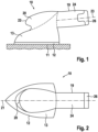
- a first embodiment of a device 10 for surface treatment is shown, which is designed here, for example, as a grinding device, but in another embodiment can be designed as a polishing device, polishing machine or similar working device.
- the device 10 is designed to drive a working tool 11, whereby this working tool 11 in the case shown consists of a grinding tool 12.
- the device 10 contains in a housing 13 an electric motor 14, a gear 15 connected downstream of this and an output 16, which is only indicated schematically, for driving the working tool 11, in particular the grinding tool 12.
- the working tool 11 can, as in a multi-grinder, have the shape of an iron or, as is known for example in eccentric grinders, have a round shape.
- the triangular or iron-shaped design of the grinding tool 12 is shown as an example.
- the device is provided with a battery power supply 17 for the electric motor 14.
- This battery power supply 17 has, for example, at least one replaceable battery pack 18 or, instead, battery cells not shown.
- the device 10 has a mono-block shape, in which the housing 13 is located above the surface of the grinding tool 12. This surface is not or only slightly overhanged by the housing 13 at the sides.
- the housing 13 is located within a construction space, which can be imagined by projecting the grinding surface in the vertical direction in Fig.1 upwards can be imagined.
- a protruding handle 19 engages the housing 13.
- the handle 19 is used to handle the device 10, e.g. to guide the device.
- the upper area, which extends vertically above the working tool 11 and which is connected to the handle 19 at the side, is designed as an additional handle and/or additional gripping surface 20.
- This additional handle or this additional gripping surface 20 is designed to grasp and apply a vertical contact force to the working tool 11 during handling. This takes into account the specifications regarding the handling of such a device 10. When grinding, polishing or similar processing operations, force must be applied in different directions. On the one hand, the necessary contact pressure must be applied to the surface of the working tool 11 in an essentially vertical direction.
- the device 10 must be moved in alternating grinding directions, e.g. in the direction of the Fig.2 indicated housing longitudinal alignment 21 and transversely thereto.
- the inventive design of the device shape and arrangement of the handle 19 and the additional handle or the additional grip surface 20 makes it possible to guide the device 10 with one hand and to apply the contact pressure required for processing, e.g. for grinding, directly over the surface of the working tool 11, in particular the grinding tool 12, with the other hand.
- one-hand operation is also possible on one of the two handles 19 and 20.
- the additional Grip surface or the additional handle 20 have according to Fig.1 a nose-like contour with projection 22 that projects to the left. This can further improve the handling of the device 10.
- devices 10 with battery power supply 17 are usually lighter and have lower performance than mains-powered devices. Due to the lower weight, a larger proportion of the contact pressure must be applied by the user when processing using a device 10. This is made easier by the additional handle 19 and also the additional grip surface or the additional handle 20, whereby the handle 19 not only enables the device 10 to be guided as precisely as possible but can also contribute to the transfer of the contact pressure to the surface of the working tool 11.
- the handle 19 is located at a distance above the working surface of the working tool 11 and at the side next to it.
- the handle 19 is therefore located entirely or at least largely outside the installation space of the device 10, which is limited by the vertical projection of the working surface of the working tool 11.
- the additional grip surface 20 or the additional handle is located vertically above the working surface of the working tool 11 and does not protrude beyond the said installation space or only protrudes to a small extent.
- the handle 19 has a clearly elongated shape, although in another embodiment not shown, a spherical shape can also be used.
- the handle 19 is designed as a hand-grip handle due to its elongated shape and cross-sectional design. It has cross-sectional areas that are preferably round, oval and/or square. Cross-sectional areas of the handle 19 can also be a combination of the aforementioned cross-sectional areas.
- the length of the handle 19 can be between 7 cm and 10 cm, although even longer sizes are also conceivable. A length of at least 9.5 cm can be particularly advantageous, for example.
- the handle 19 can be firmly and permanently connected to the housing 13. It can be attached to the housing 13 or placed on top of it. Instead, the handle 19 can also be integral with the housing 13. In other designs, the handle 19 is, for example, detachably connected to the housing 13 and can be adjusted in relation to the housing 13 and fixed in the respectively set position.
- the elongated handle 19 can be positioned with its longitudinal central axis 23 at an angle with respect to the plane of the working tool 11 upwards and/or obliquely to the side and/or can be adjusted to such positions.
- the handle 19 is positioned with its longitudinal center axis 23, for example, transversely to the longitudinal alignment 21 of the housing.
- Such a handle position is also included in the adjustability of the handle 19.
- one in which the handle 19 is pivoted about a vertical axis and locked in the desired position could be particularly advantageous.
- a pivot adjustment with subsequent locking about such a transverse axis is possible, which, like the longitudinal center axis 23, is in Fig.4 horizontally and transversely to the housing longitudinal alignment 21.
- the handle 19 has a handle housing 24 with an inner cavity 25 and a removable wall 26 for closing the cavity 25.
- the wall 26 consists, for example, of an end cover.
- Battery cells or the at least one replaceable battery pack 18 and/or components 27 are arranged in the cavity 25 of the handle housing 24, which can consist, for example, of an electronic circuit board 28, a switch (not shown in more detail) or the like.
- a switch not shown in more detail
- the transition between the removable wall 26 and the handle housing 24 is preferably smooth and as stepless as possible.
- the wall 26, e.g. the end cover is completely or partially part of the battery pack 18.
- the handle housing 24 extends to the housing 13 of the device 10 and is, for example, detachably mounted on or in the housing 13.
- the transition is designed to be as smooth and stepless as possible.
- the device 10 can be designed flatter in the area above the surface of the working tool 11.
- the additional grip surface 20 or the additional handle, which run vertically above the surface of the working tool 11, can thus be moved closer to the surface of the working tool 11. This allows for more stable operation of the device 10.
- a device 10 according to the invention with a battery power supply 17 for the electric motor 14 is lighter than mains devices and is particularly suitable for processing vertical surfaces, e.g. walls, windows, doors or the like, or for overhead work.
- the device 10 according to the invention is simple and safe to operate and handle, and allows for fatigue-free use.
- the additional grip surface or the additional handle 20 is only indicated with dashed lines 20 of the housing 13.
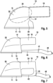
- the Fig.1 The projection 22 shown above the working tool 11 as part of the housing 13 is omitted in the housing 13 in Fig.5 .
- the housing 13 has a concave recess 31 in the vertical area 30 adjacent to the handle 19 between the handle 19 and the working tool 11.
- This recess 31 means that the transition area of the elongated handle 19 to the housing 13 is not at the level of the end of the working surface of the working tool 11 but in Fig.5 is shifted further to the left over this surface of the working tool 11.
- the working surface of the working tool 11 thus protrudes in this area 30 beyond the attachment of the handle 19 on the housing 13.
- This design has the advantage that the overall length of the device 10 is reduced, with the center of gravity of the device 10 being shifted on the longitudinal alignment 21 of the housing in the direction of the surface of the working tool 11. This reduces any tendency to tip over due to any heavy components that may be contained in the cavity 25 of the handle 19.
- the housing 13 and/or the handle housing 24 are preferably made of a technical plastic and injection-molded parts. However, metallic materials such as aluminum, steel, zinc or the like are also possible.
- the device 10 is provided with a suction hose that can be connected to the housing 13 for abrasion material that is produced during processing.
- the device 10 is provided with a channel element 42 that has a connection point 41 for the suction hose 40 and shifts the connection point of the housing 13 for the suction hose 40 at least to the end of the handle 19.
- the channel element 42 runs slightly above the height of the working tool 11 without hindering processing with it, with a large gap being present between the underside of the handle 19 and the channel element 42, which provides a sufficiently large reach-through height between the The comprehensive handle 19 and the channel element 42 are ensured.
- the channel element 42 can also be provided as an adapter. It is advantageously designed to be flatter than the suction hose 40.
- the channel element 42 is supported at the end by means of a support element 43 which leads to the handle 19, in relation to the handle 19.
- a support element 43 which leads to the handle 19, in relation to the handle 19.
- the channel element 42 and the support element 43 are combined with the handle 19 to form a one-piece component. It can be advantageous for the one-piece component to be integrated into the housing 13, e.g. to be in one piece with it.
Landscapes
- Engineering & Computer Science (AREA)
- Mechanical Engineering (AREA)
- Finish Polishing, Edge Sharpening, And Grinding By Specific Grinding Devices (AREA)
Description
- Die Erfindung geht aus von einem Schleifgerät nach dem Oberbegriff des Anspruchs 1.
- Aus der
EP 1 491 290 A1 ist bereits ein solches Schleifgerät bekannt, in dessen Hohlraum zur Stromversorgung des Elektromotors eine Leitung hineinführt. Das Gerät ist als Netzgerät gestaltet und ist demgemäß relativ groß und schwer. - In der Regel sind Akku-betriebene Schleifgeräte im Vergleich zu Netzgeräten, die größer und schwerer sind, leistungsschwächer und leichter. Wegen des geringeren Gewichts muss ein größerer Anteil der Anpresskraft für die Bearbeitung eines Werkstücks vom Benutzer aufgebracht werden. Dies zeigt sich vor allem dann nachteilig, wenn der Benutzer sich die Vorteile der kabellosen Ausführung und des geringeren Gewichts insbesondere für die Bearbeitung vertikaler Flächen oder für Überkopfarbeiten nutzbar machen möchte.
- Ferner wird auf die Druckschriften
EP 1 506 840 A1 ,US 5 947 804 A ,US 5 074 081 A ,JP 11 151652 A WO 2006/134742 A1 , sowieEP 0 804 985 A1 ,US 2010/120340 A1 ,WO 2009/006587 undDE 20 2009 002787 U1 verwiesen. - Das Dokument
GB 2 457 173 A - Die Erfindung betrifft ein Schleifgerät zur Oberflächenbehandlung mit den Merkmalen des Anspruchs 1. Vorteilhafte Weiterbildungen ergeben sich aus den abhängigen Ansprüchen.
- Das erfindungsgemäße Schleifgerät hat den Vorteil, dass es aufgrund der Form- und Griffgestaltung eine Zweihandbedienung und eine verbesserte Bedienbarkeit erlaubt. Der abstehende Griff macht es möglich, das Gerät mit einer Hand zu führen. Ein in vertikaler Richtung oberhalb des Schleifwerkzeuges, im Folgenden auch als Arbeitswerkzeug bezeichnet, befindlicher Zusatzgriff oder eine entsprechende gehäuseseitige zusätzliche Grifffläche macht es möglich, mit der zweiten Hand die für die Bearbeitung erforderliche Anpresskraft direkt über dem Arbeitswerkzeug aufzubringen. Weiterhin ist aber auch eine Einhandbedienung durch Angreifen entweder an dem Griff oder an den zusätzlichen gehäuseseitigen Griffflächen möglich. Der wegen des geringen Gewichts des Akku-betriebenen Geräts erforderliche größere Anteil der Anpresskraft kann vom Benutzer somit gut und ermüdungsfrei aufgebracht werden, wobei der Griff zusätzlich bei der exakten Führung des Gerätes hilft. Das Gerät ist klein, kompakt, leicht und einfach und betriebssicher zu handhaben. Ferner kann das Gerät im Bereich oberhalb der Arbeitsfläche des Arbeitswerkzeuges flacher gestaltet werden, wobei die zusätzliche gehäuseseitige Grifffläche oder der dortige Zusatzgriff oberhalb des Arbeitswerkzeuges näher an dessen Arbeitsfläche heranrücken kann, was eine stabilere Handhabung des Gerätes ermöglicht.
- Die Erfindung sieht vor, dass der obere Gehäusebereich, der sich vertikal oberhalb des des Schleifwerkzeuges erstreckt und seitlich an den Griff anschließt, als Zusatzgriff oder zusätzliche Grifffläche zum Anfassen und Aufbringen einer vertikalen Anpresskraft des Schleifwerkzeuges ausgebildet ist. Vorteilhaft kann es dabei sein, wenn dieser Zusatzgriff in vertikaler Richtung über der Arbeitsfläche des Arbeitswerkzeuges liegt und nicht oder nur zu einem kleinen Teil über den Bauraum des Gerätes hinausragt, der durch die vertikale Projektion der Arbeitsfläche des Arbeitswerkzeuges in vertikaler Richtung begrenzt ist. Der abstehende Griff hingegen ragt über diese Arbeitsfläche des Arbeitswerkzeuges vollständig oder zumindest zu einem Großteil hinaus.
- Der Griff kann eine kugelige Form aufweisen oder ist zweckmäßigerweise länglich gestaltet. Von Vorteil ist es, wenn der Griff als von Hand umfassbarer Umfassungsgriff ausgebildet ist und Querschnittsbereiche aufweist, die vorzugsweise rund, oval und/oder eckig sind oder die aus derartigen Querschnittsbereichen kombiniert sind. Die Länge des Griffes kann z. B. etwa zwischen 7 cm und 10 cm betragen.
- Vorteilhaft kann es ferner sein, wenn der Griff am Gehäuse fest und unlösbar angebracht ist oder statt dessen lösbar und/oder in Bezug auf das Gehäuse verstellbar und in der jeweils eingestellten Position fixierbar ist. Dadurch ist der Griff an die jeweiligen Arbeitsbedingungen einfach und praktisch anpassbar. Der länglich geformte Griff kann z. B. mit seiner Längsmittelachse unter einem Winkel in Bezug auf die Ebene des Schleifwerkzeuges nach oben oder auch nach unten und/oder zur Seite schräg positioniert sein oder positionierbar sein. Auch eine Ausrichtung quer zur Gehäuselängsrichtung als fest eingestellte oder einstellbare Griffposition ist möglich.
- Von Vorteil kann es ferner sein, wenn zwischen dem Griffgehäuse und der Wandung ein möglichst glatter stufenfreier Übergang ausgebildet ist. Das Griffgehäuse kann mit dem Gerätegehäuse einstückig sein oder es ist statt dessen an dieses angesetzt oder auf dieses aufgesetzt.
- Von Vorteil kann es ferner sein, wenn das Gehäuse im vertikalen, an den Griff angrenzenden Bereich zwischen Griff und Arbeitswerkzeug, insbesondere Schleifwerkzeug, eine konkave Eintiefung aufweist. Dies hat den Vorteil, dass sich unter Beibehaltung der angestrebten Länge des Griffes der Griffüberstand über die Arbeitsfläche des Arbeitswerkzeuges verringern lässt und damit die Gesamtlänge des Gerätes kleiner wird. Auch wird eine Verschiebung des Schwerpunkts des Geräts weg vom Griff in horizontaler Richtung hin zum Arbeitswerkzeug erreicht. Dadurch wird eine etwaige Kippneigung bei der Handhabung des Geräts z. B. durch relativ schwere Komponenten im Hohlraum des Griffes reduziert.
- Eine weitere vorteilhafte Ausführungsform sieht bei einem Gerät mit einem an das Gehäuse anschließbaren Absaugschlauch für bei der Bearbeitung entstehendes Abriebmaterial ein Kanalelement vor, das die Anschlußstelle des Gehäuses für den Absaugschlauch zumindest bis zum Ende des Griffes verlagert, so dass der Absaugschlauch erst im Bereich des Endes des Griffes an das Kanalelement angeschlossen werden kann. Das Kanalelement verläuft zweckmäßigerweise nur geringfügig über der Höhe des Schleifwerkzeuges und in relativ großem Abstand unterhalb des Griffes, wobei der Abstand so groß ist, dass der Umfassungsgriff störungsfrei und sicher umfasst werden kann.
- Vorteilhaft kann es ferner sein, wenn das Kanalelement am Ende mittels eines zum Griff führenden Stützelements in Bezug auf den Griff abgestützt ist. Eine weitere vorteilhafte Ausführungsform sieht vor, dass das Kanalelement mit dem Stützelement und dem Griff zu einem einstückigen Bauteil vereinigt ist. Das einstückige Bauteil kann in das Gehäuse integriert sein, z. B. damit einstückig sein.
- Die Erfindung ist anhand von in den Zeichnungen dargestellten Ausführungsbeispielen in der nachfolgenden Beschreibung näher erläutert. Es zeigen jeweils in schematischer Darstellung:
- Fig. 1
- eine schematische Seitenansicht eines Geräts zur Oberflächenbehandlung in Gestalt eines Schleifgeräts, gemäß einem ersten Ausführungsbeispiel,
- Fig. 2
- eine schematische Draufsichts des Geräts in
Fig. 1 , - Fig. 3
- einen schematischen axialen Längsschnitt eines Teils des Gerätes gemäß
Fig. 1 und 2 , - Fig. 4
- eine schematische Draufsicht eines Gerätes zur Oberflächenbehandlung gemäß einem zweiten Ausführungsbeispiel,
- Fig. 5
- eine schematische Seitenansicht etwa entsprechend derjenigen in
Fig. 1 eines Gerätes zur Oberflächenbehandlung gemäß einem dritten Ausführungsbeispiel, - Fig. 6
- eine schematische Seitenansicht eines Geräts zur Oberflächenbehandlung gemäß einem vierten Ausführungsbeispiel,
- Fig. 7
- eine schematische Seitenansicht eines Geräts zur Oberflächenbehandlung gemäß einem fünften Ausführungsbeispiel.
- In
Fig. 1 bis 3 ist ein erstes Ausführungsbeispiel eines Gerätes 10 zur Oberflächenbehandlung gezeigt, das hier z. B. als Schleifgerät ausgebildet ist, bei einem anderen Ausführungsbeispiel dagegen als Poliergerät, Poliermaschine od. dgl. Arbeitsgerät gestaltet sein kann. Das Gerät 10 ist zum Antrieb eines Arbeitswerkzeuges 11 ausgebildet, wobei dieses Arbeitswerkzeug 11 beim gezeigten Fall aus einem Schleifwerkzeug 12 besteht. Das Gerät 10 enthält in einem Gehäuse 13 einen Elektromotor 14, ein diesem nachgeschaltetes Getriebe 15 und einen nur schematisch angedeuteten Abtrieb 16 für den Antrieb des Arbeitswerkzeuges 11, insbesondere des Schleifwerkzeuges 12. Das Arbeitswerkzeug 11 kann, wie bei einem Multischleifer, etwa die Form eines Bügeleisens aufweisen oder, wie z. B. bei Exenterschleifern bekannt, eine runde Form haben. InFig. 1 und 2 ist beispielhaft die dreieckige oder etwa bügeleisenförmige Gestaltung des Schleifwerkzeuges 12 dargestellt. - Das Gerät ist mit einer Akku-Stromversorgung 17 für den Elektromotor 14 versehen. Diese Akku-Stromversorgung 17 weist beispielsweise mindestens einen wechselbaren Akkupack 18 oder statt dessen nicht dargestellte Akkuzellen auf.
- Insbesondere aus
Fig. 1 und 2 ist ersichtlich, dass das Gerät 10 etwa eine Mono-Block-Form hat, bei der sich das Gehäuse 13 über der Fläche des Schleifwerkzeuges 12 befindet. Diese Fläche wird vom Gehäuse 13 seitlich gar nicht oder nur wenig überragt. Das Gehäuse 13 befindet sich innerhalb eines Bauraums, den man sich durch die Projektion der Schleiffläche in vertikaler Richtung inFig. 1 nach oben vorstellen kann. - Man erkennt, dass außerhalb des genannten Bauraums am Gehäuse 13 ein abstehender Griff 19 angreift. Der Griff 19 dient der Handhabung des Geräts 10, z. B. zur Geräteführung. Der obere Bereich, der sich vertikal oberhalb des Arbeitswerkzeuges 11 erstreckt und der sich seitlich an den Griff 19 anschließt, ist als Zusatzgriff und/oder zusätzliche Grifffläche 20 ausgebildet. Dieser Zusatzgriff bzw. diese zusätzliche Grifffläche 20 ist zum Anfassen und Aufbringen einer vertikalen Anpresskraft des Arbeitswerkzeuges 11 bei der Handhabung gestaltet. Damit wird den Vorgaben hinsichtlich der Handhabung eines derartigen Gerätes 10 Rechnung getragen. Beim Schleifen, Polieren oder ähnlichen Bearbeitungsvorgängen ist eine Kraftaufbringung in verschiedenen Richtungen notwendig. Zum einen muss in im wesentlichen vertikaler Richtung der notwendige Anpressdruck auf die Fläche des Arbeitswerkzeuges 11 aufgebracht werden. Zum anderen muss das Gerät 10 in wechselnder Schleifrichtung bewegt werden, z. B. in Richtung der in
Fig. 2 angedeuteten Gehäuselängsausrichtung 21 und quer dazu. Die erfindungsgemäße Gestaltung der Geräteform und Anordnung des Griffes 19 sowie des Zusatzgriffes oder der zusätzlichen Grifffläche 20 ermöglicht es, mit einer Hand das Gerät 10 zu führen und mit der zweiten Hand die für die Bearbeitung, z. B. zum Schleifen, notwendige Anpresskraft direkt über der Fläche des Arbeitswerkzeuges 11, insbesondere des Schleifwerkzeuges 12, aufzubringen. Ferner ist auch eine Einhandbedinung an jeweils einem der beiden Griffe 19 bzw. 20 möglich. Die zusätzliche Grifffläche bzw. der Zusatzgriff 20 haben gemäßFig. 1 eine nasenartig nach links vorspringende Kontur mit Vorsprung 22. Dadurch kann die Handhabung des Gerätes 10 noch verbessert werden. Üblicherweise haben, bedingt durch die Bauweise und das Mobilitätscharakteristikum, Geräte 10 mit Akku-Stromversorgung 17 im Vergleich zu Netzgeräten in der Regel ein geringeres Gewicht und eine geringere Leistung. Wegen des geringeren Gewichts muss bei der Bearbeitung mittels eines Geräts 10 ein größerer Anteil der Anpresskraft vom Benutzer aufgebracht werden. Dies wird durch den zusätzlichen Griff 19 und auch die zusätzliche Grifffläche bzw. den Zusatzgriff 20 erleichtert, wobei der Griff 19 nicht nur eine möglichst genaue Führung des Gerätes 10 ermöglicht sondern zusätzlich auch noch zur Übertragung der Anpresskraft auf die Fläche des Arbeitswerkzeuges 11 beitragen kann. - Insbesondere aus
Fig. 1 und 2 ist ersichtlich, dass der Griff 19 in Abstand über der Arbeitsfläche des Arbeitswerkzeuges 11 und dabei seitlich neben dieser liegt. Der Griff 19 befindet sich somit ganz oder zumindest zu einem Großteil außerhalb des Bauraums des Gerätes 10, der durch die vertikale Projektion der Arbeitsfläche des Arbeitswerkzeuges 11 begrenzt wird. Die zusätzliche Grifffläche 20 oder der Zusatzgriff liegt in vertikaler Richtung über der Arbeitsfläche des Arbeitswerkzeuges 11 und ragt nicht oder nur zu einem geringen Teil über den besagten Bauraum hinaus. - Der Griff 19 weist eine deutlich längliche Form auf, obwohl bei einem anderen, nicht gezeigten Ausführungsbeispiel z. B. auch eine kugelige Form zum Einsatz kommen kann. Der Griff 19 ist durch die längliche Form und durch die Querschnittsgestaltung als von Hand umfassbarer Umfassungsgriff ausgebildet. Er weist Querschnittsbereiche auf, die vorzugsweise rund, oval und/oder eckig sind. Auch können Querschnittsbereiche des Griffes 19 aus vorgenannten Querschnittsbereichen kombiniert sein. Die Länge des Griffes 19 kann etwa zwischen 7 cm und 10 cm betragen, wobei aber auch noch längere Größen denkbar sind. Als besonders vorteilhaft kann z. B. eine Länge von mindestens 9,5 cm sein.
- Der Griff 19 kann mit dem Gehäuse 13 fest und unlösbar verbunden sein. Er kann an das Gehäuse 13 angesetzt oder darauf aufgesetzt sein. Statt dessen kann der Griff 19 mit dem Gehäuse 13 auch einstückig sein. Bei anderen Gestaltungen ist der Griff 19 z. B. lösbar mit dem Gehäuse 13 verbunden und dabei z. B. in Bezug auf das Gehäuse 13 verstellbar und in der jeweils eingestellten Position fixierbar.
- Der länglich gestaltete Griff 19 kann mit seiner Längsmittelachse 23 unter einem Winkel in Bezug auf die Ebene des Arbeitswerkzeuges 11 nach oben und/oder zur Seite schräg positioniert sein und/oder auf derartige Positionen einstellbar sein.
- Bei dem in
Fig. 4 gezeigten zweiten Ausführungsbeispiel ist der Griff 19 mit seiner Längsmittelachse 23 z. B. quer zur Gehäuselängsausrichtung 21 positioniert. Auch eine solche Griffstellung ist bei der Verstellbarkeit des Griffes 19 mitumfasst. Bei den vielen Verstellmöglichkeiten könnte eine solche besonders vorteilhaft sein, bei der der Griff 19 um eine vertikale Achse geschwenkt und in der gewünschten Position arretiert wird. Statt dessen oder auch zusätzlich dazu ist eine Schwenkverstellung mit anschließender Arretierung um eine solche Querachse möglich, die wie die Längsmittelachse 23 inFig. 4 horizontal und quer zur Gehäuselängsausrichtung 21 verläuft. - Aus
Fig. 3 wird deutlich, dass der Griff 19 ein Griffgehäuse 24 mit einem inneren Hohlraum 25 und einer abnehmbaren Wandung 26 zum Verschluss des Hohlraumes 25 aufweist. Die Wandung 26 besteht z. B. aus einem endseitigen Deckel. Im Hohlraum 25 des Griffgehäuses 24 sind Akkuzellen oder der mindestens eine wechselbare Akkupack 18 und/oder Bauelemente 27 angeordnet, die z. B. aus einer Elektronikplatine 28, einem nicht weiter gezeigten Schalter od. dgl. bestehen können. Durch Abnehmen der Wandung 26, insbesondere des endseitigen Deckels, ist ein Zugriff zum Inneren des Hohlraumes 25 und dortigen Bauelementen 27 und/oder einem Akkupack 18, dort befindlichen Akkuzellen od. dgl. möglich. Der Übergang zwischen der abnehmbaren Wandung 26 und dem Griffgehäuse 24 ist vorzugsweise glatt und möglichst stufenlos. Die Wandung 26, z. B. der endseitige Deckel, ist komplett oder teilweise Teil des Akkupacks 18. - Bei einem anderen, nicht gezeigten Ausführungsbeispiel reicht das Griffgehäuse 24 bis hin zum Gehäuse 13 des Gerätes 10 und wird z. B. lösbar am oder im Gehäuse 13 aufgenommen. Auch hierbei ist der Übergang möglichst glatt und stufenfrei gestaltet. Dadurch, dass im Inneren des Griffgehäuses 24 entsprechende Elemente untergebracht sind, kann das Gerät 10 im Bereich über der Fläche des Arbeitswerkzeuges 11 flacher gestaltet werden. Die zusätzliche Grifffläche 20 bzw. der Zusatzgriff, die vertikal oberhalb der Fläche des Arbeitswerkzeuges 11 verlaufen, kann dadurch näher an die Fläche des Arbeitswerkzeuges 11 herangerückt werden. Dies erlaubt eine stabilere Bedienung des Gerätes 10. Ein Gerät 10 gemäß der Erfindung mit Akku-Stromversorgung 17 für den Elektromotor 14 hat im Vergleich zu Netzgeräten ein geringeres Gewicht und eignet sich mit besonderem Vorteil für die Bearbeitung an vertikalen Flächen, z. B. von Wänden, Fenstern, Türen od. dgl., oder auch für Überkopfarbeiten. Das Gerät 10 gemäß der Erfindung ist hinsichtlich seiner Bedienung und Handhabung einfach, sicher und ermöglicht einen ermüdungsarmen Einsatz.
- Bei den folgenden Ausführungsbeispielen gemäß
Fig. 5 bis 7 sind für die Teile, die den ersten Ausführungsbeispielen inFig. 1 bis 3 entsprechen, gleiche Bezugszeichen verwendet, so dass dadurch zur Vermeidung von Wiederholungen auf die Beschreibung des ersten Ausführungsbeispieles Bezug genommen ist. - In
Fig. 5 ist die zusätzliche Grifffläche bzw. der Zusatzgriff 20 nur mit gestrichtelten Linien 20 des Gehäuses 13 angedeutet. Der inFig. 1 gezeigte Vorsprung 22 oberhalb des Arbeitswerkzeuges 11 als Teil des Gehäuses 13 entfällt beim Gehäuse 13 inFig. 5 . Hier ist als Besonderheit gezeigt, dass das Gehäuse 13 im vertikalen, an den Griff 19 angrenzenden Bereich 30 zwischen Griff 19 und Arbeitswerkzeug 11 eine konkave Eintiefung 31 aufweist. Diese Eintiefung 31 führt dazu, dass der Übergangsbereich des länglichen Griffes 19 zum Gehäuse 13 nicht auf der Höhe des dortigen Endes der Arbeitsfläche des Arbeitswerkzeuges 11 liegt sondern inFig. 5 weiter nach links über dieses Fläche des Arbeitswerkzeuges 11 verschoben ist. Die Arbeitsfläche des Arbeitswerkzeuges 11 ragt in diesem Bereich 30 somit über den Ansatz des Griffes 19 am Gehäuse 13 hinaus. Diese Gestaltung hat den Vorteil, dass die Gesamtlänge des Gerätes 10 kleiner wird, wobei der Schwerpunkt des Gerätes 10 auf der Gehäuselängsausrichtung 21 in Richtung zur Fläche des Arbeitswerkzeuges 11 verschoben wird. Dadurch wird eine eventuelle Kippneigung durch etwaige schwere Komponenten, die im Hohlraum 25 des Griffes 19 enthalten sein können, verringert. - Das Gehäuse 13 und/oder das Griffgehäuse 24 bestehen vorzugsweise aus einem technischen Kunststoff und aus Spritzgußteilen. Es sind aber auch metallische Werkstoffe wie Aluminium, Stahl, Zink od. dgl. möglich.
- Bei dem in
Fig. 6 gezeigten Ausführungsbeispiel ist das Gerät 10 mit einem an das Gehäuse 13 anschließbaren Absaugschlauch für bei der Bearbeitung entstehendes Abriebmaterial versehen. Für diese Gestaltung mit Absaugung ist das Gerät 10 mit einem Kanalelement 42 versehen, das eine Anschlussstelle 41 für den Absaugschlauch 40 aufweist und die Anschlussstelle des Gehäuses 13 für den Absaugschlauch 40 zumindest bis zum Ende des Griffes 19 verlagert. Das Kanalelement 42 verläuft geringfügig über der Höhe des Arbeitswerkzeuges 11, ohne die Bearbeitung mit diesem zu behindern, wobei zwischen der Unterseite des Griffes 19 und dem Kanalelement 42 ein großer Zwischenraum vorhanden ist, der eine ausreichend große Durchgreifhöhe zwischen dem zu umfassenden Griff 19 und dem Kanalelement 42 gewährleistet. Das Kanalelement 42 kann als Adapter zusätzlich vorgesehen sein. Es ist in vorteilhafter Weise flacher gestaltet als der Absaugschlauch 40. - Wie sich aus
Fig. 7 ergibt, ist das Kanalelement 42 am Ende mittels eines Stützelements 43, das zum Griff 19 führt, in Bezug auf den Griff 19 abgestützt. In vorteilhafter Weise können gemäßFig. 7 das Kanalelement 42 und das Stützelement 43 mit dem Griff 19 zu einem einstückigen Bauteil vereinigt sein. Von Vorteil kann es dabei sein, dass das einstückige Bauteil in das Gehäuse 13 integriert ist, z. B. damit einstückig ist.
Claims (12)
- Schleifgerät zur Oberflächenbehandlung, das zum Antrieb eines Schleifwerkzeuges (12) in einem Gehäuse (13) einen Elektromotor (14) und ein Getriebe (15) enthält und mit einer Akku-Stromversorgung (17) für den Elektromotor (14) versehen ist, wobei in Abstand über und seitlich neben dem Schleifwerkzeug (12) am Gehäuse (13) ein abstehender Griff (19) zur Handhabung, z. B. zur Geräteführung, angreift, der ein abstehendes Griffgehäuse (24) mit einem inneren Hohlraum (25) aufweist, dadurch gekennzeichnet, dass im Hohlraum (25) des Griffgehäuses (24) mindestens ein wechselbarer Akkupack (18) zur Akku-Stromversorgung oder mindestens ein wechselbarer Akkupack (18) zur Akku-Stromversorgung und Bauelemente (27), wie z. B. eine Elektronikplatine (28), ein Schalter od. dgl., angeordnet sind und der Griff (19) eine abnehmbare Wandung (26), z.B. einen endseitigen Deckel, zum Verschluss des Hohlraumes (25) aufweist, wobei die Wandung (26) komplett oder teilweise Teil des Akkupacks (18) ist, wobei der obere Gehäusebereich, der sich vertikal oberhalb des Schleifwerkzeuges (12) erstreckt und seitlich an den Griff (19) anschließt, als Zusatzgriff (20) oder zusätzliche Grifffläche zum Anfassen und Aufbringen einer vertikalen Anpresskraft des Schleifwerkzeuges (12) ausgebildet ist.
- Schleifgerät nach Anspruch 1, dadurch gekennzeichnet, dass der Griff (19) eine kugelige oder längliche Form aufweist.
- Schleifgerät nach einem der Ansprüche 1 bis 2, dadurch gekennzeichnet, dass der Griff (19) als von Hand umfassbarer Umfassungsgriff ausgebildet ist und Querschnittsbereiche aufweist, die vorzugsweise rund, oval und/oder eckig sind oder aus derartigen Querschnittsbereichen kombiniert sind.
- Schleifgerät nach Anspruch 2 oder 3, dadurch gekennzeichnet, dass die Länge des Griffs (19) in länglicher Form zumindest zwischen 7 cm und 10 cm beträgt.
- Schleifgerät nach einem der Ansprüche 1 bis 4, dadurch gekennzeichnet, dass der Griff (19) am Gehäuse fest und unlösbar oder lösbar und/oder in Bezug auf das Gehäuse (13) verstellbar und in der jeweils eingestellten Position fixierbar ist.
- Schleifgerät nach einem der Ansprüche 2 bis 5, dadurch gekennzeichnet, dass der Griff (19) in länglicher Form mit seiner Längsmittelachse (23) unter einem Winkel in Bezug auf die Ebene des Schleifwerkzeuges (12) nach oben und/oder zur Seite schräg positioniert ist oder vorzugsweise quer zur Gehäuselängsausrichtung (21) positioniert ist oder auf derartige Positionen einstellbar ist.
- Schleifgerät nach Anspruch 1, dadurch gekennzeichnet, dass das Griffgehäuse (24) mit dem Gehäuse (13) einstückig ist oder an dieses angesetzt oder darauf aufgesetzt ist.
- Schleifgerät nach einem der Ansprüche 1 bis 7, dadurch gekennzeichnet, dass das Gehäuse (13) im vertikalen, an den Griff (19) angrenzenden Bereich (30) zwischen Griff (19) und Schleifwerkzeug (12) eine konkave Eintiefung (31) aufweist.
- Schleifgerät nach einem der Ansprüche 1 bis 8, mit einem an das Gehäuse (13) anschließbaren Absaugschlauch (40) für bei der Bearbeitung entstehendes Abriebmaterial, gekennzeichnet durch ein die Anschlussstelle des Gehäuses (13) für den Absaugschlauch (40) zumindest bis zum Griffende verlagerndes Kanalelement (42), das in Abstand unterhalb des Griffs (19) und geringfügig über der Höhe des Schleifwerkzeuges (12) verläuft.
- Schleifgerät nach Anspruch 9, dadurch gekennzeichnet, dass das Kanalelement (42) am Ende mittels eines zum Griff (19) führenden Stützelements (43) in Bezug auf den Griff (19) abgestützt ist.
- Schleifgerät nach Anspruch 9 oder 10, dadurch gekennzeichnet, dass das Kanalelement (42) mit dem Stützelement (43) und dem Griff (19) zu einem einstückigen Bauteil vereinigt ist.
- Schleifgerät nach Anspruch 11, dadurch gekennzeichnet, dass das einstückige Bauteil in das Gehäuse (13) integriert ist, z. B. damit einstückig ist.
Applications Claiming Priority (2)
| Application Number | Priority Date | Filing Date | Title |
|---|---|---|---|
| DE102010039152A DE102010039152A1 (de) | 2010-08-10 | 2010-08-10 | Gerät zur Oberflächenbehandlung, insbesondere Schleifgerät, Poliergerät od. dgl. |
| PCT/EP2011/060359 WO2012019816A1 (de) | 2010-08-10 | 2011-06-21 | Gerät zur oberflächenbehandlung, insbesondere schleifgerät, poliergerät od. dgl. |
Publications (2)
| Publication Number | Publication Date |
|---|---|
| EP2603353A1 EP2603353A1 (de) | 2013-06-19 |
| EP2603353B1 true EP2603353B1 (de) | 2024-06-12 |
Family
ID=44584134
Family Applications (1)
| Application Number | Title | Priority Date | Filing Date |
|---|---|---|---|
| EP11726452.3A Active EP2603353B1 (de) | 2010-08-10 | 2011-06-21 | Schleifgerät zur oberflächenbehandlung |
Country Status (6)
| Country | Link |
|---|---|
| EP (1) | EP2603353B1 (de) |
| CN (1) | CN103180099A (de) |
| DE (1) | DE102010039152A1 (de) |
| ES (1) | ES2992738T3 (de) |
| RU (1) | RU2592340C2 (de) |
| WO (1) | WO2012019816A1 (de) |
Families Citing this family (3)
| Publication number | Priority date | Publication date | Assignee | Title |
|---|---|---|---|---|
| DE102013225885A1 (de) * | 2013-12-13 | 2015-06-18 | Robert Bosch Gmbh | Batteriebetriebener Exzenterschleifer mit einer wiederaufladbaren Batterie |
| DE102014202218A1 (de) | 2014-02-06 | 2015-08-06 | Robert Bosch Gmbh | Handwerkzeugmaschine mit einem elektronisch kommutierten Elektromotor |
| US10632589B2 (en) | 2016-08-29 | 2020-04-28 | Black & Decker Inc. | Power tool |
Citations (5)
| Publication number | Priority date | Publication date | Assignee | Title |
|---|---|---|---|---|
| EP0804985A1 (de) * | 1996-04-29 | 1997-11-05 | Black & Decker Inc. | Motorgetriebenes Handwerkzeug mit einem übergossenen Gehäuse |
| WO2009006587A1 (en) * | 2007-07-03 | 2009-01-08 | Milwaukee Electric Tool Corporation | Pipe cutter |
| DE202009002787U1 (de) * | 2009-02-27 | 2009-05-20 | Robert Bosch Gmbh | Akkupack |
| GB2457173A (en) * | 2008-02-11 | 2009-08-12 | Milwaukee Electric Tool Corp | A Power Tool |
| US20100120340A1 (en) * | 2008-11-12 | 2010-05-13 | Masatoshi Fukinuki | Sander with a balance means |
Family Cites Families (18)
| Publication number | Priority date | Publication date | Assignee | Title |
|---|---|---|---|---|
| DE2741255A1 (de) * | 1977-09-14 | 1979-03-22 | Glage Geb Bohnstengel Gisela | Geraet zur flaechenbearbeitung |
| DE3010838A1 (de) * | 1980-03-21 | 1981-10-01 | Robert Bosch Gmbh, 7000 Stuttgart | Als handwerkzeugmaschine ausgebildeter schwingschleifer |
| JPS6161761A (ja) * | 1984-08-29 | 1986-03-29 | Makita Denki Seisakusho:Kk | コ−ドレス研摩機 |
| RU2032520C1 (ru) * | 1990-10-01 | 1995-04-10 | Казанский Авиационный Институт Им.А.Н.Туполева | Шлифовальная ручная машина |
| US5074081A (en) * | 1991-06-12 | 1991-12-24 | Ryobi Motor Products Corp. | Sander with removable auxiliary handle |
| RU2053103C1 (ru) * | 1991-12-02 | 1996-01-27 | Виктор Трофимович Тяжелов | Ручная машина |
| JPH11151652A (ja) * | 1997-11-21 | 1999-06-08 | Hitachi Koki Co Ltd | サンダ |
| DE29802027U1 (de) * | 1998-02-06 | 1998-03-26 | J. Wagner GmbH, 88677 Markdorf | Motorbetriebenes Handwerkzeug |
| US5947804A (en) * | 1998-04-27 | 1999-09-07 | Ryobi North America, Inc. | Adjustable eccentricity orbital tool |
| RU2152862C2 (ru) * | 1998-08-10 | 2000-07-20 | Закрытое Акционерное Общество "Энерпред" | Ручная шлифовальная машина |
| US6266850B1 (en) * | 1999-04-16 | 2001-07-31 | Interdynamics, Inc. | Hand-held tool and adjustable handle for same |
| DE29922108U1 (de) * | 1999-12-16 | 2000-02-17 | Hilti Ag, Schaan | Handgeführtes Schleifgerät |
| RU2172665C1 (ru) * | 2000-06-21 | 2001-08-27 | Ступицкий Валерий Петрович | Ручная шлифовальная машина (варианты) |
| DE10244793B4 (de) * | 2002-09-26 | 2016-11-10 | Robert Bosch Gmbh | Handwerkzeugmaschinengehäuseeinheit |
| DE10329828B4 (de) * | 2003-06-27 | 2009-06-18 | Festool Gmbh | Handwerkzeugmaschine mit Kühlvorrichtung und Staubabsaugung |
| GB0318880D0 (en) * | 2003-08-12 | 2003-09-17 | Gmca Pty Ltd | Power tool and dust and debris extraction system therefor |
| DE102004063174A1 (de) * | 2004-12-29 | 2006-07-13 | Robert Bosch Gmbh | Handwerkzeugmaschine mit einem Stabhandgriff |
| JP2006346773A (ja) * | 2005-06-14 | 2006-12-28 | Kuken:Kk | 手持ち研磨装置 |
-
2010
- 2010-08-10 DE DE102010039152A patent/DE102010039152A1/de not_active Withdrawn
-
2011
- 2011-06-21 WO PCT/EP2011/060359 patent/WO2012019816A1/de not_active Ceased
- 2011-06-21 CN CN2011800395000A patent/CN103180099A/zh active Pending
- 2011-06-21 RU RU2013110234/02A patent/RU2592340C2/ru active
- 2011-06-21 EP EP11726452.3A patent/EP2603353B1/de active Active
- 2011-06-21 ES ES11726452T patent/ES2992738T3/es active Active
Patent Citations (5)
| Publication number | Priority date | Publication date | Assignee | Title |
|---|---|---|---|---|
| EP0804985A1 (de) * | 1996-04-29 | 1997-11-05 | Black & Decker Inc. | Motorgetriebenes Handwerkzeug mit einem übergossenen Gehäuse |
| WO2009006587A1 (en) * | 2007-07-03 | 2009-01-08 | Milwaukee Electric Tool Corporation | Pipe cutter |
| GB2457173A (en) * | 2008-02-11 | 2009-08-12 | Milwaukee Electric Tool Corp | A Power Tool |
| US20100120340A1 (en) * | 2008-11-12 | 2010-05-13 | Masatoshi Fukinuki | Sander with a balance means |
| DE202009002787U1 (de) * | 2009-02-27 | 2009-05-20 | Robert Bosch Gmbh | Akkupack |
Also Published As
| Publication number | Publication date |
|---|---|
| RU2013110234A (ru) | 2014-09-20 |
| EP2603353A1 (de) | 2013-06-19 |
| WO2012019816A1 (de) | 2012-02-16 |
| DE102010039152A1 (de) | 2012-02-16 |
| RU2592340C2 (ru) | 2016-07-20 |
| CN103180099A (zh) | 2013-06-26 |
| ES2992738T3 (en) | 2024-12-17 |
Similar Documents
| Publication | Publication Date | Title |
|---|---|---|
| EP1116551B1 (de) | Handgeführtes Schleifgerät | |
| EP1719581B1 (de) | Handgehaltene Schleifmaschine mit schwenkbarem Werkzeugkopf und Werkzeughalteeinrichtung | |
| EP3389951B1 (de) | "akkubetriebene handwerkzeugmaschine i" | |
| EP2040868A1 (de) | Handwerkzeugmaschine, insbesondere handsäge | |
| EP2383076A2 (de) | Vorsatzgerät für eine Hand-Werkzeugmaschine und damit ausgestattete Hand-Werkzeugmaschine | |
| DE10039777A1 (de) | Batteriegespeistes Elektrowerkzeug | |
| EP2756928A2 (de) | Handwerkzeugmaschine mit einem ergonomischen Handgriff | |
| DE102012219638B4 (de) | Rohrbandschleifeinheit | |
| DE202010014781U1 (de) | Elektrowerkzeug, insbesondere handbetätigbares Elektrowerkzeug | |
| EP2140931A1 (de) | Rührmaschine mit längsverstellbarer Werkzeugaufnahme | |
| EP3389952B1 (de) | Akkubetriebene handwerkzeugmaschine iii | |
| EP2603353A1 (de) | Gerät zur oberflächenbehandlung, insbesondere schleifgerät, poliergerät od. dgl. | |
| WO2006042770A2 (de) | Wendeschneidblatt mit zumindest zwei schneiden sowie schneidblatthalterung | |
| DE102013210391A1 (de) | Elektrowerkzeug | |
| DE29802027U1 (de) | Motorbetriebenes Handwerkzeug | |
| EP0558893B1 (de) | Als Handgerät ausgebildetes, motorisch angetriebenes Gerät zum Schleifen, Polieren, Entrosten oder dergleichen Bearbeitung von Oberflächen | |
| DE202018004060U1 (de) | Handgriff für eine Handwerkzeugmaschine | |
| DE102014222987A1 (de) | Winkelschleifer mit einem Verlängerungsabschnitt | |
| DE102004007764B3 (de) | Handwerkzeuggerät mit Abhängebügel | |
| EP3366399A1 (de) | Elektrohandgerät | |
| DE10066114B4 (de) | Betätigungshandgriff | |
| DE2941353C2 (de) | Handbandschleifmaschine mit einer Abhebeeinrichtung | |
| DE20318570U1 (de) | Griff für ein handgeführtes Arbeitsgerät | |
| DE29816970U1 (de) | Winkelschleifmaschine mit schwenkbarer Werkzeugaufnahme | |
| DE102005057328B3 (de) | Exzentertellerschleifer mit Arretiereinrichtung |
Legal Events
| Date | Code | Title | Description |
|---|---|---|---|
| PUAI | Public reference made under article 153(3) epc to a published international application that has entered the european phase |
Free format text: ORIGINAL CODE: 0009012 |
|
| 17P | Request for examination filed |
Effective date: 20130311 |
|
| AK | Designated contracting states |
Kind code of ref document: A1 Designated state(s): AL AT BE BG CH CY CZ DE DK EE ES FI FR GB GR HR HU IE IS IT LI LT LU LV MC MK MT NL NO PL PT RO RS SE SI SK SM TR |
|
| DAX | Request for extension of the european patent (deleted) | ||
| STAA | Information on the status of an ep patent application or granted ep patent |
Free format text: STATUS: EXAMINATION IS IN PROGRESS |
|
| 17Q | First examination report despatched |
Effective date: 20170918 |
|
| RAP1 | Party data changed (applicant data changed or rights of an application transferred) |
Owner name: ROBERT BOSCH GMBH |
|
| GRAP | Despatch of communication of intention to grant a patent |
Free format text: ORIGINAL CODE: EPIDOSNIGR1 |
|
| STAA | Information on the status of an ep patent application or granted ep patent |
Free format text: STATUS: GRANT OF PATENT IS INTENDED |
|
| GRAJ | Information related to disapproval of communication of intention to grant by the applicant or resumption of examination proceedings by the epo deleted |
Free format text: ORIGINAL CODE: EPIDOSDIGR1 |
|
| STAA | Information on the status of an ep patent application or granted ep patent |
Free format text: STATUS: EXAMINATION IS IN PROGRESS |
|
| GRAP | Despatch of communication of intention to grant a patent |
Free format text: ORIGINAL CODE: EPIDOSNIGR1 |
|
| STAA | Information on the status of an ep patent application or granted ep patent |
Free format text: STATUS: GRANT OF PATENT IS INTENDED |
|
| INTG | Intention to grant announced |
Effective date: 20240212 |
|
| INTC | Intention to grant announced (deleted) | ||
| INTG | Intention to grant announced |
Effective date: 20240229 |
|
| GRAS | Grant fee paid |
Free format text: ORIGINAL CODE: EPIDOSNIGR3 |
|
| GRAA | (expected) grant |
Free format text: ORIGINAL CODE: 0009210 |
|
| STAA | Information on the status of an ep patent application or granted ep patent |
Free format text: STATUS: THE PATENT HAS BEEN GRANTED |
|
| AK | Designated contracting states |
Kind code of ref document: B1 Designated state(s): AL AT BE BG CH CY CZ DE DK EE ES FI FR GB GR HR HU IE IS IT LI LT LU LV MC MK MT NL NO PL PT RO RS SE SI SK SM TR |
|
| REG | Reference to a national code |
Ref country code: GB Ref legal event code: FG4D Free format text: NOT ENGLISH |
|
| REG | Reference to a national code |
Ref country code: CH Ref legal event code: EP |
|
| REG | Reference to a national code |
Ref country code: IE Ref legal event code: FG4D Free format text: LANGUAGE OF EP DOCUMENT: GERMAN |
|
| REG | Reference to a national code |
Ref country code: DE Ref legal event code: R096 Ref document number: 502011017470 Country of ref document: DE |
|
| PG25 | Lapsed in a contracting state [announced via postgrant information from national office to epo] |
Ref country code: BG Free format text: LAPSE BECAUSE OF FAILURE TO SUBMIT A TRANSLATION OF THE DESCRIPTION OR TO PAY THE FEE WITHIN THE PRESCRIBED TIME-LIMIT Effective date: 20240612 |
|
| PG25 | Lapsed in a contracting state [announced via postgrant information from national office to epo] |
Ref country code: FI Free format text: LAPSE BECAUSE OF FAILURE TO SUBMIT A TRANSLATION OF THE DESCRIPTION OR TO PAY THE FEE WITHIN THE PRESCRIBED TIME-LIMIT Effective date: 20240612 Ref country code: HR Free format text: LAPSE BECAUSE OF FAILURE TO SUBMIT A TRANSLATION OF THE DESCRIPTION OR TO PAY THE FEE WITHIN THE PRESCRIBED TIME-LIMIT Effective date: 20240612 |
|
| REG | Reference to a national code |
Ref country code: LT Ref legal event code: MG9D |
|
| PG25 | Lapsed in a contracting state [announced via postgrant information from national office to epo] |
Ref country code: GR Free format text: LAPSE BECAUSE OF FAILURE TO SUBMIT A TRANSLATION OF THE DESCRIPTION OR TO PAY THE FEE WITHIN THE PRESCRIBED TIME-LIMIT Effective date: 20240913 |
|
| REG | Reference to a national code |
Ref country code: NL Ref legal event code: MP Effective date: 20240612 |
|
| PGFP | Annual fee paid to national office [announced via postgrant information from national office to epo] |
Ref country code: ES Payment date: 20240703 Year of fee payment: 14 |
|
| PG25 | Lapsed in a contracting state [announced via postgrant information from national office to epo] |
Ref country code: LV Free format text: LAPSE BECAUSE OF FAILURE TO SUBMIT A TRANSLATION OF THE DESCRIPTION OR TO PAY THE FEE WITHIN THE PRESCRIBED TIME-LIMIT Effective date: 20240612 |
|
| PG25 | Lapsed in a contracting state [announced via postgrant information from national office to epo] |
Ref country code: NO Free format text: LAPSE BECAUSE OF FAILURE TO SUBMIT A TRANSLATION OF THE DESCRIPTION OR TO PAY THE FEE WITHIN THE PRESCRIBED TIME-LIMIT Effective date: 20240912 Ref country code: LV Free format text: LAPSE BECAUSE OF FAILURE TO SUBMIT A TRANSLATION OF THE DESCRIPTION OR TO PAY THE FEE WITHIN THE PRESCRIBED TIME-LIMIT Effective date: 20240612 Ref country code: HR Free format text: LAPSE BECAUSE OF FAILURE TO SUBMIT A TRANSLATION OF THE DESCRIPTION OR TO PAY THE FEE WITHIN THE PRESCRIBED TIME-LIMIT Effective date: 20240612 Ref country code: GR Free format text: LAPSE BECAUSE OF FAILURE TO SUBMIT A TRANSLATION OF THE DESCRIPTION OR TO PAY THE FEE WITHIN THE PRESCRIBED TIME-LIMIT Effective date: 20240913 Ref country code: FI Free format text: LAPSE BECAUSE OF FAILURE TO SUBMIT A TRANSLATION OF THE DESCRIPTION OR TO PAY THE FEE WITHIN THE PRESCRIBED TIME-LIMIT Effective date: 20240612 Ref country code: BG Free format text: LAPSE BECAUSE OF FAILURE TO SUBMIT A TRANSLATION OF THE DESCRIPTION OR TO PAY THE FEE WITHIN THE PRESCRIBED TIME-LIMIT Effective date: 20240612 Ref country code: RS Free format text: LAPSE BECAUSE OF FAILURE TO SUBMIT A TRANSLATION OF THE DESCRIPTION OR TO PAY THE FEE WITHIN THE PRESCRIBED TIME-LIMIT Effective date: 20240912 |
|
| PG25 | Lapsed in a contracting state [announced via postgrant information from national office to epo] |
Ref country code: NL Free format text: LAPSE BECAUSE OF FAILURE TO SUBMIT A TRANSLATION OF THE DESCRIPTION OR TO PAY THE FEE WITHIN THE PRESCRIBED TIME-LIMIT Effective date: 20240612 |
|
| PG25 | Lapsed in a contracting state [announced via postgrant information from national office to epo] |
Ref country code: NL Free format text: LAPSE BECAUSE OF FAILURE TO SUBMIT A TRANSLATION OF THE DESCRIPTION OR TO PAY THE FEE WITHIN THE PRESCRIBED TIME-LIMIT Effective date: 20240612 |
|
| PG25 | Lapsed in a contracting state [announced via postgrant information from national office to epo] |
Ref country code: PT Free format text: LAPSE BECAUSE OF FAILURE TO SUBMIT A TRANSLATION OF THE DESCRIPTION OR TO PAY THE FEE WITHIN THE PRESCRIBED TIME-LIMIT Effective date: 20241014 |
|
| REG | Reference to a national code |
Ref country code: ES Ref legal event code: FG2A Ref document number: 2992738 Country of ref document: ES Kind code of ref document: T3 Effective date: 20241217 |
|
| PG25 | Lapsed in a contracting state [announced via postgrant information from national office to epo] |
Ref country code: PT Free format text: LAPSE BECAUSE OF FAILURE TO SUBMIT A TRANSLATION OF THE DESCRIPTION OR TO PAY THE FEE WITHIN THE PRESCRIBED TIME-LIMIT Effective date: 20241014 |
|
| PG25 | Lapsed in a contracting state [announced via postgrant information from national office to epo] |
Ref country code: PL Free format text: LAPSE BECAUSE OF FAILURE TO SUBMIT A TRANSLATION OF THE DESCRIPTION OR TO PAY THE FEE WITHIN THE PRESCRIBED TIME-LIMIT Effective date: 20240612 |
|
| PG25 | Lapsed in a contracting state [announced via postgrant information from national office to epo] |
Ref country code: EE Free format text: LAPSE BECAUSE OF FAILURE TO SUBMIT A TRANSLATION OF THE DESCRIPTION OR TO PAY THE FEE WITHIN THE PRESCRIBED TIME-LIMIT Effective date: 20240612 |
|
| PG25 | Lapsed in a contracting state [announced via postgrant information from national office to epo] |
Ref country code: IS Free format text: LAPSE BECAUSE OF FAILURE TO SUBMIT A TRANSLATION OF THE DESCRIPTION OR TO PAY THE FEE WITHIN THE PRESCRIBED TIME-LIMIT Effective date: 20241012 |
|
| PG25 | Lapsed in a contracting state [announced via postgrant information from national office to epo] |
Ref country code: CZ Free format text: LAPSE BECAUSE OF FAILURE TO SUBMIT A TRANSLATION OF THE DESCRIPTION OR TO PAY THE FEE WITHIN THE PRESCRIBED TIME-LIMIT Effective date: 20240612 |
|
| PG25 | Lapsed in a contracting state [announced via postgrant information from national office to epo] |
Ref country code: RO Free format text: LAPSE BECAUSE OF FAILURE TO SUBMIT A TRANSLATION OF THE DESCRIPTION OR TO PAY THE FEE WITHIN THE PRESCRIBED TIME-LIMIT Effective date: 20240612 Ref country code: SK Free format text: LAPSE BECAUSE OF FAILURE TO SUBMIT A TRANSLATION OF THE DESCRIPTION OR TO PAY THE FEE WITHIN THE PRESCRIBED TIME-LIMIT Effective date: 20240612 |
|
| PG25 | Lapsed in a contracting state [announced via postgrant information from national office to epo] |
Ref country code: SM Free format text: LAPSE BECAUSE OF FAILURE TO SUBMIT A TRANSLATION OF THE DESCRIPTION OR TO PAY THE FEE WITHIN THE PRESCRIBED TIME-LIMIT Effective date: 20240612 |
|
| PG25 | Lapsed in a contracting state [announced via postgrant information from national office to epo] |
Ref country code: SM Free format text: LAPSE BECAUSE OF FAILURE TO SUBMIT A TRANSLATION OF THE DESCRIPTION OR TO PAY THE FEE WITHIN THE PRESCRIBED TIME-LIMIT Effective date: 20240612 Ref country code: SK Free format text: LAPSE BECAUSE OF FAILURE TO SUBMIT A TRANSLATION OF THE DESCRIPTION OR TO PAY THE FEE WITHIN THE PRESCRIBED TIME-LIMIT Effective date: 20240612 Ref country code: RO Free format text: LAPSE BECAUSE OF FAILURE TO SUBMIT A TRANSLATION OF THE DESCRIPTION OR TO PAY THE FEE WITHIN THE PRESCRIBED TIME-LIMIT Effective date: 20240612 Ref country code: PL Free format text: LAPSE BECAUSE OF FAILURE TO SUBMIT A TRANSLATION OF THE DESCRIPTION OR TO PAY THE FEE WITHIN THE PRESCRIBED TIME-LIMIT Effective date: 20240612 Ref country code: IS Free format text: LAPSE BECAUSE OF FAILURE TO SUBMIT A TRANSLATION OF THE DESCRIPTION OR TO PAY THE FEE WITHIN THE PRESCRIBED TIME-LIMIT Effective date: 20241012 Ref country code: EE Free format text: LAPSE BECAUSE OF FAILURE TO SUBMIT A TRANSLATION OF THE DESCRIPTION OR TO PAY THE FEE WITHIN THE PRESCRIBED TIME-LIMIT Effective date: 20240612 Ref country code: CZ Free format text: LAPSE BECAUSE OF FAILURE TO SUBMIT A TRANSLATION OF THE DESCRIPTION OR TO PAY THE FEE WITHIN THE PRESCRIBED TIME-LIMIT Effective date: 20240612 |
|
| PG25 | Lapsed in a contracting state [announced via postgrant information from national office to epo] |
Ref country code: LU Free format text: LAPSE BECAUSE OF NON-PAYMENT OF DUE FEES Effective date: 20240621 |
|
| REG | Reference to a national code |
Ref country code: DE Ref legal event code: R097 Ref document number: 502011017470 Country of ref document: DE |
|
| PG25 | Lapsed in a contracting state [announced via postgrant information from national office to epo] |
Ref country code: MC Free format text: LAPSE BECAUSE OF FAILURE TO SUBMIT A TRANSLATION OF THE DESCRIPTION OR TO PAY THE FEE WITHIN THE PRESCRIBED TIME-LIMIT Effective date: 20240612 |
|
| PG25 | Lapsed in a contracting state [announced via postgrant information from national office to epo] |
Ref country code: MC Free format text: LAPSE BECAUSE OF FAILURE TO SUBMIT A TRANSLATION OF THE DESCRIPTION OR TO PAY THE FEE WITHIN THE PRESCRIBED TIME-LIMIT Effective date: 20240612 |
|
| PG25 | Lapsed in a contracting state [announced via postgrant information from national office to epo] |
Ref country code: DK Free format text: LAPSE BECAUSE OF FAILURE TO SUBMIT A TRANSLATION OF THE DESCRIPTION OR TO PAY THE FEE WITHIN THE PRESCRIBED TIME-LIMIT Effective date: 20240612 |
|
| PLBE | No opposition filed within time limit |
Free format text: ORIGINAL CODE: 0009261 |
|
| STAA | Information on the status of an ep patent application or granted ep patent |
Free format text: STATUS: NO OPPOSITION FILED WITHIN TIME LIMIT |
|
| PG25 | Lapsed in a contracting state [announced via postgrant information from national office to epo] |
Ref country code: IE Free format text: LAPSE BECAUSE OF NON-PAYMENT OF DUE FEES Effective date: 20240621 |
|
| PG25 | Lapsed in a contracting state [announced via postgrant information from national office to epo] |
Ref country code: BE Free format text: LAPSE BECAUSE OF NON-PAYMENT OF DUE FEES Effective date: 20240630 |
|
| REG | Reference to a national code |
Ref country code: BE Ref legal event code: MM Effective date: 20240630 |
|
| 26N | No opposition filed |
Effective date: 20250313 |
|
| PGFP | Annual fee paid to national office [announced via postgrant information from national office to epo] |
Ref country code: GB Payment date: 20250620 Year of fee payment: 15 |
|
| PGFP | Annual fee paid to national office [announced via postgrant information from national office to epo] |
Ref country code: FR Payment date: 20250626 Year of fee payment: 15 |
|
| REG | Reference to a national code |
Ref country code: AT Ref legal event code: MM01 Ref document number: 1693827 Country of ref document: AT Kind code of ref document: T Effective date: 20240621 |
|
| PG25 | Lapsed in a contracting state [announced via postgrant information from national office to epo] |
Ref country code: SE Free format text: LAPSE BECAUSE OF FAILURE TO SUBMIT A TRANSLATION OF THE DESCRIPTION OR TO PAY THE FEE WITHIN THE PRESCRIBED TIME-LIMIT Effective date: 20240612 |
|
| PGFP | Annual fee paid to national office [announced via postgrant information from national office to epo] |
Ref country code: DE Payment date: 20250814 Year of fee payment: 15 |
|
| PGFP | Annual fee paid to national office [announced via postgrant information from national office to epo] |
Ref country code: IT Payment date: 20250630 Year of fee payment: 15 |
|
| PG25 | Lapsed in a contracting state [announced via postgrant information from national office to epo] |
Ref country code: AT Free format text: LAPSE BECAUSE OF NON-PAYMENT OF DUE FEES Effective date: 20240621 |
|
| PGFP | Annual fee paid to national office [announced via postgrant information from national office to epo] |
Ref country code: CH Payment date: 20250701 Year of fee payment: 15 |
|
| PG25 | Lapsed in a contracting state [announced via postgrant information from national office to epo] |
Ref country code: CY Free format text: LAPSE BECAUSE OF FAILURE TO SUBMIT A TRANSLATION OF THE DESCRIPTION OR TO PAY THE FEE WITHIN THE PRESCRIBED TIME-LIMIT; INVALID AB INITIO Effective date: 20110621 |
|
| PG25 | Lapsed in a contracting state [announced via postgrant information from national office to epo] |
Ref country code: HU Free format text: LAPSE BECAUSE OF FAILURE TO SUBMIT A TRANSLATION OF THE DESCRIPTION OR TO PAY THE FEE WITHIN THE PRESCRIBED TIME-LIMIT; INVALID AB INITIO Effective date: 20110621 |