EP2600329B1 - External environment recognition device for vehicle, and light distribution control system using same - Google Patents
External environment recognition device for vehicle, and light distribution control system using same Download PDFInfo
- Publication number
- EP2600329B1 EP2600329B1 EP11812326.4A EP11812326A EP2600329B1 EP 2600329 B1 EP2600329 B1 EP 2600329B1 EP 11812326 A EP11812326 A EP 11812326A EP 2600329 B1 EP2600329 B1 EP 2600329B1
- Authority
- EP
- European Patent Office
- Prior art keywords
- vehicle
- oncoming
- region
- driving
- turning radius
- Prior art date
- Legal status (The legal status is an assumption and is not a legal conclusion. Google has not performed a legal analysis and makes no representation as to the accuracy of the status listed.)
- Active
Links
Images


Classifications
-
- B—PERFORMING OPERATIONS; TRANSPORTING
- B60—VEHICLES IN GENERAL
- B60Q—ARRANGEMENT OF SIGNALLING OR LIGHTING DEVICES, THE MOUNTING OR SUPPORTING THEREOF OR CIRCUITS THEREFOR, FOR VEHICLES IN GENERAL
- B60Q1/00—Arrangement of optical signalling or lighting devices, the mounting or supporting thereof or circuits therefor
- B60Q1/02—Arrangement of optical signalling or lighting devices, the mounting or supporting thereof or circuits therefor the devices being primarily intended to illuminate the way ahead or to illuminate other areas of way or environments
- B60Q1/04—Arrangement of optical signalling or lighting devices, the mounting or supporting thereof or circuits therefor the devices being primarily intended to illuminate the way ahead or to illuminate other areas of way or environments the devices being headlights
- B60Q1/14—Arrangement of optical signalling or lighting devices, the mounting or supporting thereof or circuits therefor the devices being primarily intended to illuminate the way ahead or to illuminate other areas of way or environments the devices being headlights having dimming means
- B60Q1/1415—Dimming circuits
- B60Q1/1423—Automatic dimming circuits, i.e. switching between high beam and low beam due to change of ambient light or light level in road traffic
- B60Q1/143—Automatic dimming circuits, i.e. switching between high beam and low beam due to change of ambient light or light level in road traffic combined with another condition, e.g. using vehicle recognition from camera images or activation of wipers
-
- G—PHYSICS
- G06—COMPUTING OR CALCULATING; COUNTING
- G06F—ELECTRIC DIGITAL DATA PROCESSING
- G06F17/00—Digital computing or data processing equipment or methods, specially adapted for specific functions
-
- G—PHYSICS
- G06—COMPUTING OR CALCULATING; COUNTING
- G06V—IMAGE OR VIDEO RECOGNITION OR UNDERSTANDING
- G06V20/00—Scenes; Scene-specific elements
- G06V20/50—Context or environment of the image
- G06V20/56—Context or environment of the image exterior to a vehicle by using sensors mounted on the vehicle
- G06V20/58—Recognition of moving objects or obstacles, e.g. vehicles or pedestrians; Recognition of traffic objects, e.g. traffic signs, traffic lights or roads
- G06V20/582—Recognition of moving objects or obstacles, e.g. vehicles or pedestrians; Recognition of traffic objects, e.g. traffic signs, traffic lights or roads of traffic signs
-
- G—PHYSICS
- G08—SIGNALLING
- G08G—TRAFFIC CONTROL SYSTEMS
- G08G1/00—Traffic control systems for road vehicles
- G08G1/16—Anti-collision systems
- G08G1/165—Anti-collision systems for passive traffic, e.g. including static obstacles, trees
-
- B—PERFORMING OPERATIONS; TRANSPORTING
- B60—VEHICLES IN GENERAL
- B60Q—ARRANGEMENT OF SIGNALLING OR LIGHTING DEVICES, THE MOUNTING OR SUPPORTING THEREOF OR CIRCUITS THEREFOR, FOR VEHICLES IN GENERAL
- B60Q2300/00—Indexing codes for automatically adjustable headlamps or automatically dimmable headlamps
- B60Q2300/05—Special features for controlling or switching of the light beam
- B60Q2300/056—Special anti-blinding beams, e.g. a standard beam is chopped or moved in order not to blind
-
- B—PERFORMING OPERATIONS; TRANSPORTING
- B60—VEHICLES IN GENERAL
- B60Q—ARRANGEMENT OF SIGNALLING OR LIGHTING DEVICES, THE MOUNTING OR SUPPORTING THEREOF OR CIRCUITS THEREFOR, FOR VEHICLES IN GENERAL
- B60Q2300/00—Indexing codes for automatically adjustable headlamps or automatically dimmable headlamps
- B60Q2300/40—Indexing codes relating to other road users or special conditions
- B60Q2300/41—Indexing codes relating to other road users or special conditions preceding vehicle
-
- B—PERFORMING OPERATIONS; TRANSPORTING
- B60—VEHICLES IN GENERAL
- B60Q—ARRANGEMENT OF SIGNALLING OR LIGHTING DEVICES, THE MOUNTING OR SUPPORTING THEREOF OR CIRCUITS THEREFOR, FOR VEHICLES IN GENERAL
- B60Q2300/00—Indexing codes for automatically adjustable headlamps or automatically dimmable headlamps
- B60Q2300/40—Indexing codes relating to other road users or special conditions
- B60Q2300/42—Indexing codes relating to other road users or special conditions oncoming vehicle
-
- G—PHYSICS
- G06—COMPUTING OR CALCULATING; COUNTING
- G06V—IMAGE OR VIDEO RECOGNITION OR UNDERSTANDING
- G06V10/00—Arrangements for image or video recognition or understanding
- G06V10/20—Image preprocessing
- G06V10/25—Determination of region of interest [ROI] or a volume of interest [VOI]
-
- G—PHYSICS
- G06—COMPUTING OR CALCULATING; COUNTING
- G06V—IMAGE OR VIDEO RECOGNITION OR UNDERSTANDING
- G06V20/00—Scenes; Scene-specific elements
- G06V20/50—Context or environment of the image
- G06V20/56—Context or environment of the image exterior to a vehicle by using sensors mounted on the vehicle
- G06V20/58—Recognition of moving objects or obstacles, e.g. vehicles or pedestrians; Recognition of traffic objects, e.g. traffic signs, traffic lights or roads
- G06V20/584—Recognition of moving objects or obstacles, e.g. vehicles or pedestrians; Recognition of traffic objects, e.g. traffic signs, traffic lights or roads of vehicle lights or traffic lights
-
- G—PHYSICS
- G08—SIGNALLING
- G08G—TRAFFIC CONTROL SYSTEMS
- G08G1/00—Traffic control systems for road vehicles
- G08G1/16—Anti-collision systems
- G08G1/166—Anti-collision systems for active traffic, e.g. moving vehicles, pedestrians, bikes
Definitions
- the present invention relates an external environment recognizing device for vehicle that detects a preceding vehicle and an oncoming vehicle using an image pickup device such as a camera and a light distribution control system using the external environment recognizing device for vehicle.
- US 2008/181461 A1 describes a monitoring system including an image capture module for capturing an image, an object detecting unit for detecting an object from the image, a monitoring range setting unit for setting a monitoring range in a side of the object on the image, a determining unit for determining the existence of a light source within the monitoring range, and an adjusting unit for adjusting one of an exposure amount of the image capture and a luminance of a pixel output from the image capture when the determining unit determines the existence of the light source.
- the light distribution control system divides an irradiation range of headlights of an own vehicle into a plurality of small regions and adjusts the intensity and the height of beams in the respective regions to thereby prevent drivers of other vehicles from being dazzled while increasing visibility for the driver at night.
- a method of detecting a preceding vehicle and an oncoming vehicle at night for example, there is a method of extracting, using, for example, a vehicle-mounted camera, headlights of the oncoming vehicle and taillights of the preceding vehicle out of points of white light and points of red light reflected in an image.
- light sources such as streetlights and reflected lights of reflectors are present on a road besides lights of other vehicles. All the light sources are reflected in a camera image as points of light. Therefore, it is necessary to identify light sources of the other vehicles and light sources other than the light sources of the other vehicles out of the light sources. In particular, the reflected lights of the reflectors present on the road tend to be misrecognized as headlights of oncoming vehicles.
- PTL 1 describes a method of recognizing a white line and determining that light on the recognized white line is not an oncoming vehicle.
- PTL 2 describes a method of changing a signal processing range of a radar according to road information acquired from a navigation system.
- misdetection cannot be eliminated when positional deviation of the navigation system occurs or while a vehicle is traveling on a road not covered by the navigation system such as a newly-constructed road.
- the present invention has been devised in view of the above points and it is an object of the present invention to provide an external environment recognizing device for vehicle that can prevent, for example, reflected light of a reflector from being misrecognized as an oncoming vehicle even on a road where a white line and information of a navigation system is not obtained and a light distribution control system using the external environment recognizing device for vehicle.
- the present invention provides an external environment recognizing device for vehicle including: an image acquiring unit configured to acquire an image obtained by picking up an image of an area ahead of an own vehicle; a light-source extracting unit configured to extract a light source from the acquired image; an own-vehicle-speed acquiring unit configured to acquire own vehicle speed; an oncoming-vehicle-presence-possible-region setting unit configured to estimate an oncoming vehicle presence possible region on the basis of the own vehicle speed; and an oncoming-vehicle detecting unit configured to detect an oncoming vehicle on the basis of the oncoming vehicle presence possible region and the light source.
- the oncoming-vehicle-presence-possible-region setting unit estimates the oncoming vehicle presence possible region on the basis of the own vehicle speed, a minimum curvature radius of a traveling road corresponding to a speed limit determined in advance, and traffic information indicating whether driving on the traveling road is driving on the right side or driving on the left side.
- the present invention provides a light distribution control system including: an external environment recognizing device for vehicle including an image acquiring unit configured to acquire an image obtained by picking up an image of an area ahead of an own vehicle, a light-source extracting unit configured to extract a light source from the acquired image, an own-vehicle-speed acquiring unit configured to acquire own vehicle speed, an oncoming-vehicle-presence-possible-region setting unit configured to estimate an oncoming vehicle presence possible region on the basis of the own vehicle speed, and an oncoming-vehicle detecting unit configured to detect an oncoming vehicle on the basis of the oncoming vehicle presence possible region and the light source and output information concerning the oncoming vehicle; and a light distribution control device including a beam control unit configured to control irradiation intensity of a headlight.
- the external environment recognizing device for vehicle includes an oncoming-vehicle-information transmitting unit configured to transmit information concerning the oncoming vehicle output from the oncoming-vehicle detecting unit to the light distribution control device.
- the oncoming-vehicle-presence-possible-region setting unit estimates the oncoming vehicle presence possible region on the basis of the own vehicle speed, a minimum curvature radius of a traveling road corresponding to a speed limit determined in advance, and traffic information indicating whether driving on the traveling road is driving on the right side or driving on the left side.
- an external environment recognizing device for vehicle that can prevent, for example, reflected light of a reflector from being misrecognized as an oncoming vehicle even on a road where a white line and information of a navigation system is not obtained and a light distribution control system using the external environment recognizing device for vehicle.
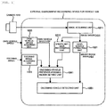
- Fig. 1 is a block diagram of an external environment recognizing device for vehicle 1000 according to the present invention.
- the external environment recognizing device for vehicle 1000 is incorporated, for example, in a camera 1010 mounted on an automobile or in an integrated controller and used to recognize an environment around the own vehicle from an image photographed by the camera 1010.
- the external environment recognizing device for vehicle 1000 is configured to detect an oncoming vehicle and a preceding vehicle from an image obtained by picking up an image of an area ahead of the own vehicle.
- the external environment recognizing device for vehicle 1000 is configured by a computer including a CPU, a memory, and an I/O.
- the external environment recognizing device for vehicle 1000 is programmed with predetermined processing to repeatedly execute processing at a period set in advance.
- the external environment recognizing device for vehicle 1000 includes, as shown in Fig. 1 , an image acquiring unit 1011, a light-source extracting unit 1021, an own-vehicle-speed acquiring unit 1031, an oncoming-vehicle-presence-possible-region setting unit 1041, and an oncoming-vehicle detecting unit 1051. Further, depending on an embodiment, the external environment recognizing device for vehicle 1000 includes a steering-angle acquiring unit 1111 and a speed-limit-sign recognizing unit 1211.
- the image acquiring unit 1011 captures, from the camera 1010 attached to a position where an image of an area ahead of the own vehicle can be picked up, data obtained by photographing an area ahead of the own vehicle and writes the data on a RAM as an image IMGSRC [x] [y].
- the image IMGSRC [x] [y] is a two-dimensional array and x and y respectively indicate coordinates of the image.
- the light-source extracting unit 1021 calculates, from the image IMGSRC [x] [y], a light point P_HL[i], which is a candidate of a headlight.
- P_HL[i] i is an ID number affixed when a plurality of objects are detected.
- the light point P_HL[i] has a position on an image and an area as elements.
- the position on the image of the light point P_HL[i] is represented as P_HL[i].X and P_HL[i].Y and the area is represented as P_HL [i] .A. Details of processing are explained below.
- the own-vehicle-speed acquiring unit 1031 acquires a signal of a vehicle speed sensor mounted on the own vehicle and obtains own vehicle speed VSP.
- the signal of the vehicle speed sensor may be acquired by being directly input to the external environment recognizing device for vehicle 1000 or may be acquired by performing communication using a LAN (Local Area Network) or a CAN (Controller Area Network).
- the oncoming-vehicle-presence-possible-region setting unit 1041 calculates, according to the own vehicle speed VSP, a minimum turning radius R_MIN on a traveling road of the own vehicle and calculates a range in which an oncoming vehicle is possibly present. Details of processing are explained below.
- the oncoming-vehicle detecting unit 1051 determines, according to the range in which an oncoming vehicle is possibly present, whether the calculated light point P_HL[i] is an oncoming vehicle. Details of processing are explained below.
- a position of headlights of the extracted oncoming vehicle on the image is converted into an angle in the lateral direction, which is the direction of the oncoming vehicle viewed from the own vehicle, and output from the camera.
- the output may be performed by being directly input or may be performed through communication using a LAN (Local Area Network) or a CAN (Controller Area Network).
- the output may be a position coordinate itself of the oncoming vehicle on the image or may be a world coordinate calculated from the image using a camera geometric parameter.
- the steering-angle acquiring unit 1111 acquires a signal of a steering angle sensor mounted on the own vehicle and obtains a steering angle STR of the own vehicle.
- the signal of the own steering angle sensor may be acquired by being directly input to the external environment recognizing device for vehicle 1000 or may be acquired by performing communication using a LAN (Local Area Network) or a CAN (Controller Area Network).
- the speed-limit-sign recognizing unit 1211 recognizes, from the image IMGSRC [x] [y], a sign of a speed limit on a road on which the own vehicle is traveling. Details of processing are explained below.
- a regulation of a minimum radius in a curve of a road corresponding to a speed limit and a regulation concerning a traffic direction of the road are used.
- the regulations in the case of Japan are explained.
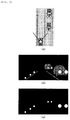
- Fig. 2 shows an example of the processing in the light-source extracting unit 1021.
- the light-source extracting unit 1021 calculates, from the image IMGSRC[x][y], the light point P_HL[i], which is possibly a headlight of an oncoming vehicle, according to predetermined processing.
- a luminance value of a pixel (x, y) of the image IMGSRC[x] [y] is equal to or larger than a predetermined thresholds Th_HL, "1" is input and, otherwise, "0" is input to the same pixel of the image IMGHL [x] [y], whereby a binary image IMGHL [x] [y] obtained by extracting a headlight candidate in the image is generated.
- the threshold Th_HL is a value adjusted such that a headlight of a vehicle desired to be detected can be extracted.
- the threshold Th_HL is determined by photographing lights of various vehicles using the camera. Alternatively, the threshold Th_HL may be manually set experimentally.
- the threshold Th_HL may be a variable value and may be changed according to a period of time or brightness of the environment or changed according to a position on an image.
- Fig. 2(c) is an example in which the binary image IMGHL [x] [y] is extracted from Fig. 2 (b) .
- white of the image represents "1" of the binary image and black represents "0".
- the light point P_HL[i] is calculated by applying labeling processing to the binary image IMGHL[x][y].
- the labeling processing is a method of extracting, from the binary image IMGHL[x][y], information concerning a region where a pixel value is "1". In this embodiment, each of regions where pixel values are "1" is set as the light point P_HL[i].
- Gravity center positions X and Y and an area A of the light point P_HL[i] are calculated.
- Processing for calculating the light point P_HL[i] from the image IMGSRC[x][y] may be a method other than the method of generating the binary image IMGHL [x] [y] and extracting the light point P_HL[i] using the labeling processing.
- the processing may be a method of registering a representative pattern of a headlight on an image in a database as a template, extracting a portion similar to the template, and setting the portion as the light point P_HL[i].
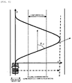
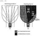
- the oncoming-vehicle-presence-possible-region setting unit 1041 calculates, from the own vehicle speed VSP acquired by the own-vehicle-speed acquiring unit 1031, an estimated minimum turning radius R_MIN on a traveling road of the own vehicle and sets an oncoming vehicle presence possible region using the estimated minimum turning radius R_MIN.
- a curve of a road can be represented as a part of a circle having a radius R.
- the structure of the road is regulated by the law.
- minimum curvature radiuses of curves of roads are determined according to speed limits. Therefore, the minimum turning radius R_MIN of a curve of a road on which the own vehicle is currently traveling can be calculated from the own vehicle speed VSP. Considering that a driver is driving exceeding a speed limit, the minimum turning radius R_MIN may be calculated from a value obtained by multiplying the own vehicle speed VSP with a predetermined coefficient ⁇ ( ⁇ 1.0).
- an oncoming vehicle presence possible region is set from the minimum turning radius R_MIN.
- the lateral direction is set as an X axis
- the depth direction is set as a Y axis
- a region on the inner side of the circle is a region where an oncoming vehicle is absent and a region other than the region is a region where an oncoming vehicle is possibly present.
- the oncoming-vehicle-presence-possible-region setting unit 1041 estimates an oncoming vehicle presence possible region on the basis of the own vehicle speed VSP, a minimum curvature radius of a traveling road corresponding to a speed limit determined in advance, and traffic information indicating whether driving on the traveling road is driving on the right side or driving on the left side.
- the oncoming-vehicle-presence-possible-region setting unit 1041 estimates the minimum turning radius R_MIN of the traveling road on the basis of the own vehicle speed VSP, a minimum curvature radius of a traveling road corresponding to a speed limit determined in advance, and traffic information indicating whether driving on the traveling road is driving on the right side or driving on the left side and estimates an oncoming vehicle presence possible region on the basis of the estimated minimum turning radius R_MIN.
- the oncoming-vehicle detecting unit 1051 determines whether points of the light point P_HL[i] shown in the binary image IMGHL [x] [y] output from the light-source extracting unit 1021 are light points of oncoming vehicles according to which of the region where an oncoming vehicle is possibly present and the region where an oncoming vehicle is absent in the world coordinate system having the vehicle front end center as the origin, which is calculated by the oncoming-vehicle-presence-possible-region setting unit 1041, the points belong to.
- the oncoming-vehicle detecting unit 1051 extracts only light points, world coordinates P_HL[i].PY and P_HL[i].PX of which are included in the oncoming vehicle presence possible region, in the light point P_HL[i] and erases light points, world coordinates P_HL[i].PY and P_HL[i].PX of which are not included in the oncoming vehicle presence possible region from P_HL[i].
- the oncoming-vehicle detecting unit 1051 extracts light points forming pairs in the light point P_HL[i]. A method of extracting light points forming pairs is explained below.
- the oncoming-vehicle detecting unit 1051 extracts all combinations (P_HL[i], P_HL[j]) of points, the Y coordinate P_HL[i].Y of which on the image is smaller than a predetermined threshold TH_Ypair, among all light points.
- the oncoming-vehicle detecting unit 1051 calculates, concerning each of the combinations, differences in a distance of an X coordinate and an area according to the following expression.
- DX i j ABS P_HL i . X ⁇ P_HL j .
- X DA i j ABS P_HL i . A ⁇ P_HL j .
- ABS() represents an absolute value.
- the oncoming-vehicle detecting unit 1051 decides that the two pairs are headlights of oncoming vehicles.
- the region where an oncoming vehicle is absent is set using the minimum turning radius R_MIN calculated according to the own vehicle speed VSP and a traffic rule indicating the driving on the left side.
- Light points which are headlight candidates, are extracted out of various light points included in a camera image. It is determined according to positions of the light points whether the light points are light points of oncoming vehicles or noise. Misdetection in which a light point that is not an oncoming vehicle is determined as an oncoming vehicle is reduced. In this way, since the misdetection can be reduced according to only own vehicle speed, the processing is effective.
- the oncoming-vehicle-presence-possible-region setting unit 1041 may take into account a yaw angle ⁇ _V of the own vehicle in addition to the minimum turning radius R_MIN.
- a vehicle changes a lane, the vehicle tilts most with respect to a lane in which the vehicle is traveling.
- the vehicle tilts most it is possible that an oncoming vehicle is present in a direction tilting by the yaw angle ⁇ _V from the front of the own vehicle.
- the oncoming-vehicle-presence-possible-region setting unit 1041 calculates a maximum yaw angle ⁇ _V of the own vehicle. Since lateral acceleration ⁇ X of a vehicle generated during a lane change is in a proportional relation with discomfort of a driver, in a normal lane change, the lateral acceleration ⁇ X of the vehicle is not a large value. Therefore, lateral accelerations during lane changes of a plurality of drivers are measured and a value larger than a maximum value of the lateral accelerations is set as maximum lateral acceleration ⁇ X_MAX.
- a track of the own vehicle in changing a lane at a distance of width W is approximated by a trigonometric function to give the vehicle speed VSP and the maximum lateral acceleration ⁇ X_MAX, whereby it is possible to calculate the maximum yaw angle ⁇ _V during the lane change on a road on which the own vehicle is currently traveling.
- the oncoming-vehicle-presence-possible-region setting unit 1041 calculates an oncoming vehicle presence possible region taking into account the maximum yaw angle ⁇ _V of the own vehicle.
- the lateral direction is set as an X axis
- the depth direction is set as a Y axis
- a circle of a left curve is drawn at a radius (R_MIN + 0.5 x vehicle width Wcar) from the right end of the own vehicle, a region on the inner side of the circle is a region where an oncoming vehicle is absent.
- an AND region of the circle of the left curve drawn at the radius (R_MIN + 0.5 x vehicle width Wcar) from the right end of the own vehicle and a region on the left side of the straight tilting to the left side by the yaw angle from the right end of the own vehicle is a region where an oncoming vehicle is absent.
- a region other than the region is an oncoming vehicle presence possible region.
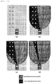
- Fig. 7 examples in (a) a 30 km per hour case, (b) a 60 km per hour case, and (c) a 90 km per hour case are shown.
- the oncoming-vehicle-presence-possible-region setting unit 1041 calculates a turning radius Rv of the own vehicle from the steering angle STR and changes a turning radium of a predicted course according to a value of the turning radius Rv.
- the stability factor is an important value that is an index indicating a magnitude of a change that depends on the speed of steady circle turning of the vehicle.
- the turning radius Rv changes in proportion to a square of the speed VSP of the own vehicle with the stability factor A set as a coefficient.
- the turning radius Rv can also be calculated by Expression (2) using the vehicle speed VSP and a yaw rate y.
- Expression 2 Rv VSP / ⁇
- the oncoming-vehicle-presence-possible-region setting unit 1041 calculates the turning radius Rv of the own vehicle using a method of Expression (1) or Expression (2).
- the oncoming-vehicle-presence-possible-region setting unit 1041 calculates the estimated minimum turning radius R_MIN in a traveling road of the own vehicle according to the turning radius Rv of the own vehicle. For example, since driving on a road in Japan is driving on the left side, when the own vehicle is turning to the right, as shown in Fig. 8 (a) , it is considered that an oncoming vehicle is absent at least further on the left side than the left end of the own vehicle.
- the speed-limit-sign recognizing unit 1211 searches for a sign indicating a speed limit from the image IMGSRC [x] [y].
- a sign indicating a speed limit for example, color information of signs and information concerning setting locates are used.
- a speed limit is displayed in blue characters on a circular sign colored in red on the outer side and colored in white on the inner side. Setting height of the sign is regulated by the law. Therefore, the speed-limit-sign recognizing unit 1211 searches for, using a publicly-known technique such as template matching, a region that satisfies such a condition from the image IMGSRC[x][y].
- the speed-limit-sign recognizing unit 1211 recognizes a number of the speed limit from the found sign.
- a pattern recognition method such as a neural network or the like, which is a publicly-known technique
- the neural network is a pattern recognition method that simulates a model of the human brain.
- learning is necessary beforehand. The learning is performed according to an algorithm called back propagation method using a teacher data set, which is a set of images of signs in various situations and speed limits drawn on the signs. Since the pattern recognition method by the neural network is a publicly-known technique, details are not explained in the present invention.
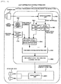
- Fig. 9 is a block diagram showing the embodiment of the light distribution control system 4000.
- Components same as the components of the external environment recognizing device for vehicle 1000 are denoted by the same reference numerals and explanation of the components is omitted.
- the light distribution control system 4000 includes, as shown in Fig. 9 , the external environment recognizing device for vehicle 2000 and the light distribution control device 3000.
- the external environment recognizing device for vehicle 2000 is incorporated, for example, in a camera mounted on an automobile or in an integrated controller and used to detect an object set in advance from an image picked up by the camera 1010.
- the external environment recognizing device for vehicle 2000 is configured to detect an oncoming vehicle and a preceding vehicle from an image obtained by picking up an image of an area ahead of the own vehicle.
- the external environment recognizing device for vehicle 2000 is configured by a computer including a CPU, a memory, and an I/O.
- the external environment recognizing device for vehicle 2000 is programmed with predetermined processing to repeatedly execute processing at a period set in advance.
- the external environment recognizing device for vehicle 2000 includes, as shown in Fig. 9 , the image acquiring unit 1011, the light-source extracting unit 1021, the own-vehicle-speed acquiring unit 1031, the oncoming-vehicle-presence-possible-region setting unit 1041, the oncoming-vehicle detecting unit 1051, and an oncoming-vehicle-information transmitting unit 2061.
- the external environment recognizing device for vehicle 2000 includes the steering-angle acquiring unit 1111 and the speed-limit-sign recognizing unit 1211.
- the light distribution control device 3000 is incorporated, for example, in a controller for headlights 3010 mounted on an automobile or in an integrated controller.
- the headlights 3010 include a beam control unit 3011 configured to switch irradiation intensity of a beam in at least two or more stages.
- a lighting device that can switch the intensity of the headlights 3010 in two stages of a low beam and a high beam is explained.
- the oncoming-vehicle-information transmitting unit 2061 transmits information concerning an oncoming vehicle detected by the oncoming-vehicle detecting unit 1051 to the light distribution control device 3000 on the outside of the external environment recognizing device for vehicle 2000.
- the information concerning the oncoming vehicle to be transmitted includes at least one of a flag fC representing presence or absence of an oncoming vehicle, an angle C ⁇ [c] with respect to a traveling direction of the own vehicle, a distance CY[c] from the own vehicle front end to the oncoming vehicle front end, and a lateral position CX[c] from the own vehicle center to the oncoming vehicle center.
- c represents an ID number affixed when a plurality of oncoming vehicles are detected.
- These kinds of position information can be calculated by a publicly-known method using a camera geometric parameter if a coordinate of the oncoming vehicle on an image is known. Therefore, detailed explanation of the information is omitted.
- These kinds of position information of the oncoming vehicle may be directly input from the external environment recognizing device for vehicle 2000 to the light distribution control device 3000 or may be communicated with a radar using a LAN (Local Area Network).
- LAN Local Area Network
- the beam control unit 3011 receives an output of the external environment recognizing device for vehicle 2000 and switches irradiation intensity of the headlights 3010.
- the beam control unit 3011 receives information concerning an oncoming vehicle received from the oncoming-vehicle-information transmitting unit 2061 mounted on the external environment recognizing device for vehicle 2000 and information concerning a preceding vehicle detected by a publicly-known method.
- the information concerning the oncoming vehicle includes at least one of the flag fC representing presence or absence of an oncoming vehicle, the angle C ⁇ [c] with respect to a traveling direction of the own vehicle, the distance CY [c] from the own vehicle front end to the oncoming vehicle front end, and the lateral position CX[c] from the own vehicle center to the oncoming vehicle center.
- the information concerning the preceding vehicle includes at least one of a flag fP representing presence or absence of a preceding vehicle, an angle P ⁇ [p] with respect to a traveling direction of the own vehicle, a distance PY [p] from the own vehicle front end to the preceding vehicle rear end, and a lateral position PX [p] from the own vehicle center to the preceding vehicle center.
- p represents an ID number affixed when a plurality of preceding vehicles are detected.
- Types of the information concerning the oncoming vehicle and the information concerning the preceding vehicle to be received are the same. For example, when the flag fC representing presence or absence of an oncoming vehicle is received, the flag fP representing presence or absence of a preceding vehicle is received. When the distance CY[c] and the angle C ⁇ [c] of the oncoming vehicle are received, the distance PY[p] and the angle P ⁇ [p] of the preceding vehicle are received.
- the high beam is irradiated if no oncoming vehicle and no preceding vehicle are present and the low beam is irradiated to prevent drivers of other vehicles from being dazzled if an oncoming vehicle or a preceding vehicle is present.
- the high beam is irradiated if a distance to closest another car is larger than a predetermined value and the low beam is irradiated if the distance is smaller than the predetermined value.
- the high beam is irradiated if both of the oncoming vehicle and the preceding vehicle are outside an irradiation range and the low beam is irradiated if the oncoming vehicle or the preceding vehicle is present in the irradiation range of the headlights.
- the intensity of a light source of the headlights may be adjusted or an irradiation angle of the headlights may be switched.
- the beam intensity may be adjusted according to a shortest distance to the own vehicle of the distance CY[c] to the oncoming vehicle and the distance PY[p] to the preceding vehicle.
- the light distribution control system 4000 determines beam intensity using the beam control unit 3011 of the light distribution control device 3000 on the basis of the information concerning the oncoming vehicle detected by the external environment recognizing device for vehicle 2000 and the information concerning the preceding vehicle detected by the publicly-known method and controls the headlights 3010. Consequently, it is possible to prevent dazzling of drivers of other vehicles by irradiating the high beam if an oncoming vehicle and a preceding vehicle are absent and irradiating the low beam if an oncoming vehicle or a preceding vehicle is present.
- the present invention can prevent, in such a system, switching from the high beam to the low beam even if a reflector or the like is present on the left side of the own vehicle.
- a lighting device is used that can divide a beam irradiation range of the headlights 3010 in a fan shape and switch irradiation intensity of a beam in two stages of a low beam and a high beam independently in respective regions.
- the beam control unit 3011 receives an output of the external environment recognizing device for vehicle 2000 and switches the irradiation intensity of the headlights 3010.
- the beam control unit 3011 receives information concerning an oncoming vehicle 51 and information concerning a preceding vehicle 52.
- the information concerning the oncoming vehicle 51 includes at least one of the angle C ⁇ [c] with respect to a traveling direction of the own vehicle, the distance CY [c] from the own vehicle front end to the oncoming vehicle front end, and the lateral position CX [c] from the own vehicle center to the oncoming vehicle center.
- the information concerning the preceding vehicle 52 includes at least one of the angle P ⁇ [p] with respect to a traveling direction of the own vehicle, the distance PY [p] from the own vehicle front end to the preceding vehicle rear end, and the lateral position PX [p] from the own vehicle center to the preceding vehicle center.
- Types of the information concerning the oncoming vehicle 51 and the information concerning the preceding vehicle 52 to be received are the same. For example, when the distance CY[c] and the angle C ⁇ [c] of the oncoming vehicle 51 are received, the distance PY [p] and the angle P ⁇ [p] of the preceding vehicle 52 are received.
- the low beam is irradiated in a region where the oncoming vehicle 51 or the preceding vehicle 52 is present and the high beam is irradiated in the other regions.
- the low beam is irradiated in the region where the oncoming vehicle 51 or the preceding vehicle 52 is present and the high beam is irradiated in the other regions.
- the intensity of a light source of the headlights may be adjusted or an irradiation angle of the headlights may be switched.
- the beam control unit 3011 controls the irradiation intensity or the irradiation angle of the headlights on the basis of received information concerning an oncoming vehicle and input information concerning a preceding vehicle.
- the beam intensity may be changed according to a distance in the region where the oncoming vehicle 51 or the preceding vehicle 52 is present.
- a vehicle travels in a scene shown in Fig. 11 (a) while using the headlights 3010 shown in Fig. 10 .
- Fig. 11 (a) when objects (reflection plates) glittering in white such as reflectors are present on the left side of the own vehicle on a road without a white line, if the own vehicle travels using the related art, light on the left side of the own vehicle is misdetected as an oncoming vehicle. Therefore, when the headlights 3110 are used, as shown in Fig. 11 (b) , the low beam is irradiated in a certain portion of the reflectors and the high beam is irradiated in the other portions. In other words, when a white line is not recognized in an image and a reflection plate such as a reflector is recognized on the road surface, the beam control unit 3011 controls the head lights to be the low beams in a region where the reflection plate is present.
- the beam control unit 3011 controls an irradiation range of the headlights on the basis of the own vehicle speed.
- the high beam is irradiated only in a range on the vehicle side among the reflectors.
- the high beam is irradiated on even the reflectors in the distance.
- the road in Japan is referred to as an example.
- the present invention can also be applied when a road situation in Japan changes and in roads in countries other than Japan using a regulation of a turning radius of a road corresponding to a speed limit and information concerning driving on the right side and driving on the left side of the road.
- the present invention is applied to oncoming vehicle detection based on a visible image picked up by a monocular camera.
- the present invention can also be applied to oncoming vehicle detection based on a stereo camera.
Landscapes
- Engineering & Computer Science (AREA)
- Physics & Mathematics (AREA)
- General Physics & Mathematics (AREA)
- Theoretical Computer Science (AREA)
- Multimedia (AREA)
- Mechanical Engineering (AREA)
- Data Mining & Analysis (AREA)
- General Engineering & Computer Science (AREA)
- Software Systems (AREA)
- Mathematical Physics (AREA)
- Databases & Information Systems (AREA)
- Lighting Device Outwards From Vehicle And Optical Signal (AREA)
- Traffic Control Systems (AREA)
Applications Claiming Priority (2)
| Application Number | Priority Date | Filing Date | Title |
|---|---|---|---|
| JP2010171302A JP5809785B2 (ja) | 2010-07-30 | 2010-07-30 | 車両用外界認識装置およびそれを用いた配光制御システム |
| PCT/JP2011/066399 WO2012014735A1 (ja) | 2010-07-30 | 2011-07-20 | 車両用外界認識装置およびそれを用いた配光制御システム |
Publications (3)
| Publication Number | Publication Date |
|---|---|
| EP2600329A1 EP2600329A1 (en) | 2013-06-05 |
| EP2600329A4 EP2600329A4 (en) | 2014-04-09 |
| EP2600329B1 true EP2600329B1 (en) | 2016-09-07 |
Family
ID=45529950
Family Applications (1)
| Application Number | Title | Priority Date | Filing Date |
|---|---|---|---|
| EP11812326.4A Active EP2600329B1 (en) | 2010-07-30 | 2011-07-20 | External environment recognition device for vehicle, and light distribution control system using same |
Country Status (4)
| Country | Link |
|---|---|
| US (1) | US9268740B2 (enExample) |
| EP (1) | EP2600329B1 (enExample) |
| JP (1) | JP5809785B2 (enExample) |
| WO (1) | WO2012014735A1 (enExample) |
Families Citing this family (29)
| Publication number | Priority date | Publication date | Assignee | Title |
|---|---|---|---|---|
| JP5760884B2 (ja) * | 2011-09-09 | 2015-08-12 | 株式会社デンソー | 車両の旋回予測装置 |
| JP5776795B2 (ja) * | 2011-12-19 | 2015-09-09 | 日産自動車株式会社 | 立体物検出装置 |
| WO2013129352A1 (ja) * | 2012-03-01 | 2013-09-06 | 日産自動車株式会社 | 立体物検出装置 |
| BR112014020404B1 (pt) * | 2012-03-01 | 2021-08-31 | Nissan Motor Co.,Ltd | Dispositivo de detecção de objeto tridimensional |
| RU2635280C2 (ru) * | 2012-03-01 | 2017-11-09 | Ниссан Мотор Ко., Лтд. | Устройство обнаружения трехмерных объектов |
| JP5873372B2 (ja) * | 2012-03-30 | 2016-03-01 | クラリオン株式会社 | ヘッドライトの配光制御装置 |
| FR2995267B1 (fr) * | 2012-09-07 | 2016-02-05 | Valeo Vision | Procede de commande d'un systeme d'eclairage adaptatif |
| JP2015033944A (ja) | 2013-08-09 | 2015-02-19 | スタンレー電気株式会社 | 車両用前照灯の点灯制御装置、車両用前照灯システム |
| US9317758B2 (en) * | 2013-08-19 | 2016-04-19 | Gentex Corporation | Vehicle imaging system and method for distinguishing reflective objects from lights of another vehicle |
| FR3010941B1 (fr) * | 2013-09-26 | 2017-01-13 | Valeo Vision | Dispositif et procede d'aide a la conduite |
| KR101607105B1 (ko) | 2014-06-20 | 2016-03-29 | 주식회사 만도 | 차량의 상향등 제어 시스템 및 상향등 제어 시스템의 제어 방법 |
| JP6493024B2 (ja) * | 2015-06-30 | 2019-04-03 | 株式会社デンソー | 表示装置、車両制御装置及び走行支援システム |
| JP6200481B2 (ja) * | 2015-11-25 | 2017-09-20 | 株式会社Subaru | 車外環境認識装置 |
| JP6310899B2 (ja) * | 2015-11-25 | 2018-04-11 | 株式会社Subaru | 車外環境認識装置 |
| JP6756507B2 (ja) * | 2016-04-01 | 2020-09-16 | 日立オートモティブシステムズ株式会社 | 環境認識装置 |
| DE102016110409A1 (de) * | 2016-06-06 | 2017-12-07 | Dr. Ing. H.C. F. Porsche Aktiengesellschaft | Verfahren zur Steuerung der Lichtverteilung einer Scheinwerferanordnung sowie eine Scheinwerferanordnung |
| KR102749979B1 (ko) * | 2016-11-09 | 2025-01-03 | 삼성전자주식회사 | 주행 차량을 위한 가상의 주행 차선을 생성하는 방법 및 장치 |
| JP6937218B2 (ja) * | 2017-10-19 | 2021-09-22 | 株式会社東芝 | 情報処理装置、情報処理方法、およびプログラム |
| CN110406456B (zh) * | 2018-04-26 | 2022-12-06 | 财团法人车辆研究测试中心 | 车辆头灯自适应避光方法 |
| CN108564819B (zh) * | 2018-05-30 | 2020-10-27 | 江苏建筑职业技术学院 | 高速公路车辆安全行驶与防止连环相撞系列报警装置与方法 |
| US11092480B2 (en) * | 2018-09-27 | 2021-08-17 | International Business Machines Corporation | Light obstruction sensor |
| CN109815879B (zh) * | 2019-01-18 | 2021-05-07 | 北京地平线机器人技术研发有限公司 | 目标检测方法、装置和电子设备 |
| KR102220950B1 (ko) * | 2019-07-31 | 2021-02-26 | 엘지전자 주식회사 | 자율 주행 시스템에서 차량을 제어하기 위한 방법 및 장치 |
| US11993333B2 (en) * | 2019-12-16 | 2024-05-28 | Koito Manufacturing Co., Ltd. | Vehicle lamp |
| DE102020007773A1 (de) | 2020-12-18 | 2021-03-04 | Daimler Ag | Verfahren zum Betreiben wenigstens eines Fahrzeugscheinwerfers und Fahrzeug |
| CN113611111B (zh) * | 2021-07-29 | 2023-09-08 | 郑州高识智能科技有限公司 | 一种基于车辆远光灯的车距计算方法 |
| CN114205947B (zh) * | 2021-12-24 | 2022-11-18 | 桂林海威科技股份有限公司 | 一种智能路灯及运行方法、智能路灯调光系统 |
| JP7629428B2 (ja) * | 2022-09-14 | 2025-02-13 | 本田技研工業株式会社 | 車両用照明装置 |
| DE102023002503A1 (de) * | 2023-06-20 | 2024-12-24 | Mercedes-Benz Group AG | Verfahren zum Steuern eines Fernlichtassistenten und der Fernlichtassistent |
Family Cites Families (22)
| Publication number | Priority date | Publication date | Assignee | Title |
|---|---|---|---|---|
| JPH06276524A (ja) * | 1993-03-19 | 1994-09-30 | Toyota Motor Corp | 対向車両認識装置 |
| JPH06274626A (ja) * | 1993-03-19 | 1994-09-30 | Toyota Motor Corp | 走行車両検出装置 |
| JPH10175478A (ja) * | 1996-12-18 | 1998-06-30 | Koito Mfg Co Ltd | 車輌用灯具装置 |
| US8120652B2 (en) * | 1997-04-02 | 2012-02-21 | Gentex Corporation | System for controlling vehicle equipment |
| JP2001114012A (ja) * | 1999-10-15 | 2001-04-24 | Koito Mfg Co Ltd | 車輌用灯具装置 |
| JP3427815B2 (ja) * | 2000-03-30 | 2003-07-22 | 株式会社デンソー | 先行車選択方法及び装置、記録媒体 |
| JP2005128790A (ja) * | 2003-10-23 | 2005-05-19 | Fuji Heavy Ind Ltd | 制限速度認識装置、制限速度表示装置、速度警報装置及び速度制御装置 |
| EP1593936B1 (en) * | 2004-04-30 | 2013-02-27 | Koito Manufacturing Co., Ltd | Lighting system for vehicle |
| JP4743037B2 (ja) | 2006-07-28 | 2011-08-10 | 株式会社デンソー | 車両検出装置 |
| JP4853160B2 (ja) * | 2006-08-02 | 2012-01-11 | 株式会社デンソー | 車両検出装置及びヘッドランプ制御装置 |
| JP2008070999A (ja) | 2006-09-13 | 2008-03-27 | Hitachi Ltd | 車両の障害物検出装置及びそれを搭載した自動車 |
| DE102006055903A1 (de) * | 2006-11-27 | 2008-05-29 | Adc Automotive Distance Control Systems Gmbh | Erkennung von Fahrzeuglichtern mit einer Kamera |
| JP4914233B2 (ja) * | 2007-01-31 | 2012-04-11 | 富士重工業株式会社 | 車外監視装置 |
| JP2009096249A (ja) * | 2007-10-15 | 2009-05-07 | Toyota Motor Corp | 車両用照明装置 |
| DE112008002582A5 (de) * | 2007-10-25 | 2010-06-24 | Adc Automotive Distance Control Systems Gmbh | Verfahren zur Unterscheidung von Fahrbahnrandreflektoren und Fahrzeuglichtern bei Dunkelheit |
| JP4982353B2 (ja) * | 2007-12-27 | 2012-07-25 | 日立オートモティブシステムズ株式会社 | 外界認識装置 |
| JP4702426B2 (ja) | 2008-10-10 | 2011-06-15 | 株式会社デンソー | 車両検出装置、車両検出プログラム、およびライト制御装置 |
| JP5286035B2 (ja) * | 2008-11-06 | 2013-09-11 | 本田技研工業株式会社 | 車速制御装置 |
| JP5363085B2 (ja) * | 2008-12-03 | 2013-12-11 | 株式会社小糸製作所 | 前照灯制御装置 |
| JP2010151692A (ja) * | 2008-12-25 | 2010-07-08 | Aisin Aw Co Ltd | 道路形状推測装置、道路形状推測方法及び道路形状推測プログラム |
| JP5353265B2 (ja) | 2009-01-26 | 2013-11-27 | パナソニック株式会社 | プラズマ処理装置 |
| US8395529B2 (en) * | 2009-04-02 | 2013-03-12 | GM Global Technology Operations LLC | Traffic infrastructure indicator on head-up display |
-
2010
- 2010-07-30 JP JP2010171302A patent/JP5809785B2/ja active Active
-
2011
- 2011-07-20 US US13/813,037 patent/US9268740B2/en active Active
- 2011-07-20 WO PCT/JP2011/066399 patent/WO2012014735A1/ja not_active Ceased
- 2011-07-20 EP EP11812326.4A patent/EP2600329B1/en active Active
Also Published As
| Publication number | Publication date |
|---|---|
| EP2600329A4 (en) | 2014-04-09 |
| WO2012014735A1 (ja) | 2012-02-02 |
| US20130131922A1 (en) | 2013-05-23 |
| JP2012030673A (ja) | 2012-02-16 |
| US9268740B2 (en) | 2016-02-23 |
| EP2600329A1 (en) | 2013-06-05 |
| JP5809785B2 (ja) | 2015-11-11 |
Similar Documents
| Publication | Publication Date | Title |
|---|---|---|
| EP2600329B1 (en) | External environment recognition device for vehicle, and light distribution control system using same | |
| KR101768500B1 (ko) | 운전 보조 장치 및 그 제어방법 | |
| JP5617999B2 (ja) | 車載周辺物認識装置及びこれを用いる運転支援装置 | |
| US10479269B2 (en) | Lighting apparatus for vehicle and vehicle having the same | |
| EP2830926B1 (en) | Vehicular imaging system and method | |
| EP2546779B1 (en) | Environment recognizing device for a vehicle and vehicle control system using the same | |
| CN103213540B (zh) | 车辆的行驶环境辨识装置 | |
| US8705796B2 (en) | Obstacle detection device | |
| US10634317B2 (en) | Dynamic control of vehicle lamps during maneuvers | |
| US9037343B2 (en) | Light distribution control apparatus and light distribution control method | |
| US20060151223A1 (en) | Device and method for improving visibility in a motor vehicle | |
| CN106295494B (zh) | 车外环境识别装置 | |
| JP2008211410A (ja) | 車載用画像認識装置及び配光制御装置、並びに配光制御方法 | |
| CN103747980A (zh) | 用于对车辆的前灯进行操控的方法和装置 | |
| CN104992160B (zh) | 一种重型卡车夜间前方车辆检测方法 | |
| JP7647267B2 (ja) | 信号機認識装置 | |
| CN119018045A (zh) | 基于场景识别的远近光自动切换控制方法及装置 | |
| US10217006B2 (en) | Method and device for detecting objects in the dark using a vehicle camera and a vehicle lighting system | |
| KR20080004833A (ko) | 주간 및 야간 주행 차량을 조도상황에 따라 검출하는 방법및 장치 | |
| JP2013163518A (ja) | 車両用前照灯装置 | |
| US20200062169A1 (en) | Controlling a controllable headlight of a motor vehicle | |
| JP2011201444A (ja) | 車両の情報伝達装置 |
Legal Events
| Date | Code | Title | Description |
|---|---|---|---|
| PUAI | Public reference made under article 153(3) epc to a published international application that has entered the european phase |
Free format text: ORIGINAL CODE: 0009012 |
|
| 17P | Request for examination filed |
Effective date: 20130228 |
|
| AK | Designated contracting states |
Kind code of ref document: A1 Designated state(s): AL AT BE BG CH CY CZ DE DK EE ES FI FR GB GR HR HU IE IS IT LI LT LU LV MC MK MT NL NO PL PT RO RS SE SI SK SM TR |
|
| DAX | Request for extension of the european patent (deleted) | ||
| A4 | Supplementary search report drawn up and despatched |
Effective date: 20140307 |
|
| RIC1 | Information provided on ipc code assigned before grant |
Ipc: B60R 1/00 20060101ALI20140303BHEP Ipc: G06K 9/00 20060101ALI20140303BHEP Ipc: G06F 17/00 20060101ALI20140303BHEP Ipc: G08G 1/16 20060101AFI20140303BHEP Ipc: G06K 9/32 20060101ALI20140303BHEP Ipc: B60Q 1/14 20060101ALI20140303BHEP |
|
| 17Q | First examination report despatched |
Effective date: 20150429 |
|
| GRAP | Despatch of communication of intention to grant a patent |
Free format text: ORIGINAL CODE: EPIDOSNIGR1 |
|
| INTG | Intention to grant announced |
Effective date: 20160419 |
|
| GRAS | Grant fee paid |
Free format text: ORIGINAL CODE: EPIDOSNIGR3 |
|
| GRAA | (expected) grant |
Free format text: ORIGINAL CODE: 0009210 |
|
| RIN1 | Information on inventor provided before grant (corrected) |
Inventor name: OHTSUJI SHINYA Inventor name: OGATA TAKEHITO Inventor name: OTSUKA YUJI |
|
| AK | Designated contracting states |
Kind code of ref document: B1 Designated state(s): AL AT BE BG CH CY CZ DE DK EE ES FI FR GB GR HR HU IE IS IT LI LT LU LV MC MK MT NL NO PL PT RO RS SE SI SK SM TR |
|
| REG | Reference to a national code |
Ref country code: GB Ref legal event code: FG4D |
|
| REG | Reference to a national code |
Ref country code: CH Ref legal event code: EP |
|
| REG | Reference to a national code |
Ref country code: IE Ref legal event code: FG4D |
|
| REG | Reference to a national code |
Ref country code: DE Ref legal event code: R096 Ref document number: 602011030231 Country of ref document: DE |
|
| REG | Reference to a national code |
Ref country code: AT Ref legal event code: REF Ref document number: 827471 Country of ref document: AT Kind code of ref document: T Effective date: 20161015 |
|
| REG | Reference to a national code |
Ref country code: LT Ref legal event code: MG4D |
|
| REG | Reference to a national code |
Ref country code: NL Ref legal event code: MP Effective date: 20160907 |
|
| PG25 | Lapsed in a contracting state [announced via postgrant information from national office to epo] |
Ref country code: HR Free format text: LAPSE BECAUSE OF FAILURE TO SUBMIT A TRANSLATION OF THE DESCRIPTION OR TO PAY THE FEE WITHIN THE PRESCRIBED TIME-LIMIT Effective date: 20160907 Ref country code: FI Free format text: LAPSE BECAUSE OF FAILURE TO SUBMIT A TRANSLATION OF THE DESCRIPTION OR TO PAY THE FEE WITHIN THE PRESCRIBED TIME-LIMIT Effective date: 20160907 Ref country code: NO Free format text: LAPSE BECAUSE OF FAILURE TO SUBMIT A TRANSLATION OF THE DESCRIPTION OR TO PAY THE FEE WITHIN THE PRESCRIBED TIME-LIMIT Effective date: 20161207 Ref country code: RS Free format text: LAPSE BECAUSE OF FAILURE TO SUBMIT A TRANSLATION OF THE DESCRIPTION OR TO PAY THE FEE WITHIN THE PRESCRIBED TIME-LIMIT Effective date: 20160907 Ref country code: LT Free format text: LAPSE BECAUSE OF FAILURE TO SUBMIT A TRANSLATION OF THE DESCRIPTION OR TO PAY THE FEE WITHIN THE PRESCRIBED TIME-LIMIT Effective date: 20160907 |
|
| REG | Reference to a national code |
Ref country code: AT Ref legal event code: MK05 Ref document number: 827471 Country of ref document: AT Kind code of ref document: T Effective date: 20160907 |
|
| PG25 | Lapsed in a contracting state [announced via postgrant information from national office to epo] |
Ref country code: NL Free format text: LAPSE BECAUSE OF FAILURE TO SUBMIT A TRANSLATION OF THE DESCRIPTION OR TO PAY THE FEE WITHIN THE PRESCRIBED TIME-LIMIT Effective date: 20160907 Ref country code: ES Free format text: LAPSE BECAUSE OF FAILURE TO SUBMIT A TRANSLATION OF THE DESCRIPTION OR TO PAY THE FEE WITHIN THE PRESCRIBED TIME-LIMIT Effective date: 20160907 Ref country code: LV Free format text: LAPSE BECAUSE OF FAILURE TO SUBMIT A TRANSLATION OF THE DESCRIPTION OR TO PAY THE FEE WITHIN THE PRESCRIBED TIME-LIMIT Effective date: 20160907 Ref country code: SE Free format text: LAPSE BECAUSE OF FAILURE TO SUBMIT A TRANSLATION OF THE DESCRIPTION OR TO PAY THE FEE WITHIN THE PRESCRIBED TIME-LIMIT Effective date: 20160907 Ref country code: GR Free format text: LAPSE BECAUSE OF FAILURE TO SUBMIT A TRANSLATION OF THE DESCRIPTION OR TO PAY THE FEE WITHIN THE PRESCRIBED TIME-LIMIT Effective date: 20161208 |
|
| PG25 | Lapsed in a contracting state [announced via postgrant information from national office to epo] |
Ref country code: RO Free format text: LAPSE BECAUSE OF FAILURE TO SUBMIT A TRANSLATION OF THE DESCRIPTION OR TO PAY THE FEE WITHIN THE PRESCRIBED TIME-LIMIT Effective date: 20160907 Ref country code: EE Free format text: LAPSE BECAUSE OF FAILURE TO SUBMIT A TRANSLATION OF THE DESCRIPTION OR TO PAY THE FEE WITHIN THE PRESCRIBED TIME-LIMIT Effective date: 20160907 |
|
| PG25 | Lapsed in a contracting state [announced via postgrant information from national office to epo] |
Ref country code: IS Free format text: LAPSE BECAUSE OF FAILURE TO SUBMIT A TRANSLATION OF THE DESCRIPTION OR TO PAY THE FEE WITHIN THE PRESCRIBED TIME-LIMIT Effective date: 20170107 Ref country code: BG Free format text: LAPSE BECAUSE OF FAILURE TO SUBMIT A TRANSLATION OF THE DESCRIPTION OR TO PAY THE FEE WITHIN THE PRESCRIBED TIME-LIMIT Effective date: 20161207 Ref country code: PT Free format text: LAPSE BECAUSE OF FAILURE TO SUBMIT A TRANSLATION OF THE DESCRIPTION OR TO PAY THE FEE WITHIN THE PRESCRIBED TIME-LIMIT Effective date: 20170109 Ref country code: CZ Free format text: LAPSE BECAUSE OF FAILURE TO SUBMIT A TRANSLATION OF THE DESCRIPTION OR TO PAY THE FEE WITHIN THE PRESCRIBED TIME-LIMIT Effective date: 20160907 Ref country code: SK Free format text: LAPSE BECAUSE OF FAILURE TO SUBMIT A TRANSLATION OF THE DESCRIPTION OR TO PAY THE FEE WITHIN THE PRESCRIBED TIME-LIMIT Effective date: 20160907 Ref country code: PL Free format text: LAPSE BECAUSE OF FAILURE TO SUBMIT A TRANSLATION OF THE DESCRIPTION OR TO PAY THE FEE WITHIN THE PRESCRIBED TIME-LIMIT Effective date: 20160907 Ref country code: AT Free format text: LAPSE BECAUSE OF FAILURE TO SUBMIT A TRANSLATION OF THE DESCRIPTION OR TO PAY THE FEE WITHIN THE PRESCRIBED TIME-LIMIT Effective date: 20160907 Ref country code: SM Free format text: LAPSE BECAUSE OF FAILURE TO SUBMIT A TRANSLATION OF THE DESCRIPTION OR TO PAY THE FEE WITHIN THE PRESCRIBED TIME-LIMIT Effective date: 20160907 Ref country code: BE Free format text: LAPSE BECAUSE OF FAILURE TO SUBMIT A TRANSLATION OF THE DESCRIPTION OR TO PAY THE FEE WITHIN THE PRESCRIBED TIME-LIMIT Effective date: 20160907 |
|
| REG | Reference to a national code |
Ref country code: DE Ref legal event code: R097 Ref document number: 602011030231 Country of ref document: DE |
|
| REG | Reference to a national code |
Ref country code: FR Ref legal event code: PLFP Year of fee payment: 7 |
|
| PG25 | Lapsed in a contracting state [announced via postgrant information from national office to epo] |
Ref country code: IT Free format text: LAPSE BECAUSE OF FAILURE TO SUBMIT A TRANSLATION OF THE DESCRIPTION OR TO PAY THE FEE WITHIN THE PRESCRIBED TIME-LIMIT Effective date: 20160907 |
|
| PLBE | No opposition filed within time limit |
Free format text: ORIGINAL CODE: 0009261 |
|
| STAA | Information on the status of an ep patent application or granted ep patent |
Free format text: STATUS: NO OPPOSITION FILED WITHIN TIME LIMIT |
|
| PG25 | Lapsed in a contracting state [announced via postgrant information from national office to epo] |
Ref country code: DK Free format text: LAPSE BECAUSE OF FAILURE TO SUBMIT A TRANSLATION OF THE DESCRIPTION OR TO PAY THE FEE WITHIN THE PRESCRIBED TIME-LIMIT Effective date: 20160907 |
|
| 26N | No opposition filed |
Effective date: 20170608 |
|
| PG25 | Lapsed in a contracting state [announced via postgrant information from national office to epo] |
Ref country code: SI Free format text: LAPSE BECAUSE OF FAILURE TO SUBMIT A TRANSLATION OF THE DESCRIPTION OR TO PAY THE FEE WITHIN THE PRESCRIBED TIME-LIMIT Effective date: 20160907 |
|
| REG | Reference to a national code |
Ref country code: CH Ref legal event code: PL |
|
| GBPC | Gb: european patent ceased through non-payment of renewal fee |
Effective date: 20170720 |
|
| REG | Reference to a national code |
Ref country code: IE Ref legal event code: MM4A |
|
| PG25 | Lapsed in a contracting state [announced via postgrant information from national office to epo] |
Ref country code: IE Free format text: LAPSE BECAUSE OF NON-PAYMENT OF DUE FEES Effective date: 20170720 Ref country code: CH Free format text: LAPSE BECAUSE OF NON-PAYMENT OF DUE FEES Effective date: 20170731 Ref country code: LI Free format text: LAPSE BECAUSE OF NON-PAYMENT OF DUE FEES Effective date: 20170731 Ref country code: GB Free format text: LAPSE BECAUSE OF NON-PAYMENT OF DUE FEES Effective date: 20170720 |
|
| REG | Reference to a national code |
Ref country code: FR Ref legal event code: PLFP Year of fee payment: 8 |
|
| PG25 | Lapsed in a contracting state [announced via postgrant information from national office to epo] |
Ref country code: LU Free format text: LAPSE BECAUSE OF NON-PAYMENT OF DUE FEES Effective date: 20170720 |
|
| PG25 | Lapsed in a contracting state [announced via postgrant information from national office to epo] |
Ref country code: MT Free format text: LAPSE BECAUSE OF NON-PAYMENT OF DUE FEES Effective date: 20170720 |
|
| PG25 | Lapsed in a contracting state [announced via postgrant information from national office to epo] |
Ref country code: AL Free format text: LAPSE BECAUSE OF FAILURE TO SUBMIT A TRANSLATION OF THE DESCRIPTION OR TO PAY THE FEE WITHIN THE PRESCRIBED TIME-LIMIT Effective date: 20160907 |
|
| PG25 | Lapsed in a contracting state [announced via postgrant information from national office to epo] |
Ref country code: HU Free format text: LAPSE BECAUSE OF FAILURE TO SUBMIT A TRANSLATION OF THE DESCRIPTION OR TO PAY THE FEE WITHIN THE PRESCRIBED TIME-LIMIT; INVALID AB INITIO Effective date: 20110720 Ref country code: MC Free format text: LAPSE BECAUSE OF FAILURE TO SUBMIT A TRANSLATION OF THE DESCRIPTION OR TO PAY THE FEE WITHIN THE PRESCRIBED TIME-LIMIT Effective date: 20160907 |
|
| PG25 | Lapsed in a contracting state [announced via postgrant information from national office to epo] |
Ref country code: CY Free format text: LAPSE BECAUSE OF NON-PAYMENT OF DUE FEES Effective date: 20160907 |
|
| PG25 | Lapsed in a contracting state [announced via postgrant information from national office to epo] |
Ref country code: MK Free format text: LAPSE BECAUSE OF FAILURE TO SUBMIT A TRANSLATION OF THE DESCRIPTION OR TO PAY THE FEE WITHIN THE PRESCRIBED TIME-LIMIT Effective date: 20160907 |
|
| PG25 | Lapsed in a contracting state [announced via postgrant information from national office to epo] |
Ref country code: TR Free format text: LAPSE BECAUSE OF FAILURE TO SUBMIT A TRANSLATION OF THE DESCRIPTION OR TO PAY THE FEE WITHIN THE PRESCRIBED TIME-LIMIT Effective date: 20160907 |
|
| REG | Reference to a national code |
Ref country code: DE Ref legal event code: R082 Ref document number: 602011030231 Country of ref document: DE Representative=s name: MERH-IP MATIAS ERNY REICHL HOFFMANN PATENTANWA, DE Ref country code: DE Ref legal event code: R081 Ref document number: 602011030231 Country of ref document: DE Owner name: HITACHI ASTEMO, LTD., HITACHINAKA-SHI, JP Free format text: FORMER OWNER: HITACHI AUTOMOTIVE SYSTEMS, LTD., HITACHINAKA-SHI, IBARAKI, JP |
|
| PGFP | Annual fee paid to national office [announced via postgrant information from national office to epo] |
Ref country code: FR Payment date: 20250610 Year of fee payment: 15 |
|
| PGFP | Annual fee paid to national office [announced via postgrant information from national office to epo] |
Ref country code: DE Payment date: 20250528 Year of fee payment: 15 |