EP2600217A1 - Numerical control apparatus - Google Patents
Numerical control apparatus Download PDFInfo
- Publication number
- EP2600217A1 EP2600217A1 EP11812081.5A EP11812081A EP2600217A1 EP 2600217 A1 EP2600217 A1 EP 2600217A1 EP 11812081 A EP11812081 A EP 11812081A EP 2600217 A1 EP2600217 A1 EP 2600217A1
- Authority
- EP
- European Patent Office
- Prior art keywords
- command
- unit time
- movement
- target object
- deceleration
- Prior art date
- Legal status (The legal status is an assumption and is not a legal conclusion. Google has not performed a legal analysis and makes no representation as to the accuracy of the status listed.)
- Withdrawn
Links
- 230000008859 change Effects 0.000 claims abstract description 244
- 238000012545 processing Methods 0.000 claims abstract description 107
- 238000012546 transfer Methods 0.000 claims abstract description 99
- 238000000034 method Methods 0.000 claims abstract description 64
- 230000008569 process Effects 0.000 claims abstract description 44
- 230000004044 response Effects 0.000 claims abstract description 27
- 230000001133 acceleration Effects 0.000 claims description 222
- 230000007423 decrease Effects 0.000 claims description 13
- 230000003247 decreasing effect Effects 0.000 claims description 7
- 230000006870 function Effects 0.000 description 107
- 238000012544 monitoring process Methods 0.000 description 46
- 230000014509 gene expression Effects 0.000 description 28
- 230000008054 signal transmission Effects 0.000 description 21
- 230000001788 irregular Effects 0.000 description 12
- 230000004043 responsiveness Effects 0.000 description 12
- 238000012508 change request Methods 0.000 description 11
- 230000036461 convulsion Effects 0.000 description 7
- 238000003825 pressing Methods 0.000 description 7
- 230000035939 shock Effects 0.000 description 7
- 230000002040 relaxant effect Effects 0.000 description 6
- 238000009825 accumulation Methods 0.000 description 3
- 230000005540 biological transmission Effects 0.000 description 2
- 238000010586 diagram Methods 0.000 description 2
- 238000009434 installation Methods 0.000 description 2
- 230000008901 benefit Effects 0.000 description 1
- 230000004069 differentiation Effects 0.000 description 1
- 238000012986 modification Methods 0.000 description 1
- 230000004048 modification Effects 0.000 description 1
Images


Classifications
-
- G—PHYSICS
- G05—CONTROLLING; REGULATING
- G05B—CONTROL OR REGULATING SYSTEMS IN GENERAL; FUNCTIONAL ELEMENTS OF SUCH SYSTEMS; MONITORING OR TESTING ARRANGEMENTS FOR SUCH SYSTEMS OR ELEMENTS
- G05B19/00—Programme-control systems
- G05B19/02—Programme-control systems electric
- G05B19/18—Numerical control [NC], i.e. automatically operating machines, in particular machine tools, e.g. in a manufacturing environment, so as to execute positioning, movement or co-ordinated operations by means of programme data in numerical form
- G05B19/402—Numerical control [NC], i.e. automatically operating machines, in particular machine tools, e.g. in a manufacturing environment, so as to execute positioning, movement or co-ordinated operations by means of programme data in numerical form characterised by control arrangements for positioning, e.g. centring a tool relative to a hole in the workpiece, additional detection means to correct position
-
- G—PHYSICS
- G05—CONTROLLING; REGULATING
- G05B—CONTROL OR REGULATING SYSTEMS IN GENERAL; FUNCTIONAL ELEMENTS OF SUCH SYSTEMS; MONITORING OR TESTING ARRANGEMENTS FOR SUCH SYSTEMS OR ELEMENTS
- G05B19/00—Programme-control systems
- G05B19/02—Programme-control systems electric
- G05B19/18—Numerical control [NC], i.e. automatically operating machines, in particular machine tools, e.g. in a manufacturing environment, so as to execute positioning, movement or co-ordinated operations by means of programme data in numerical form
- G05B19/416—Numerical control [NC], i.e. automatically operating machines, in particular machine tools, e.g. in a manufacturing environment, so as to execute positioning, movement or co-ordinated operations by means of programme data in numerical form characterised by control of velocity, acceleration or deceleration
-
- G—PHYSICS
- G05—CONTROLLING; REGULATING
- G05B—CONTROL OR REGULATING SYSTEMS IN GENERAL; FUNCTIONAL ELEMENTS OF SUCH SYSTEMS; MONITORING OR TESTING ARRANGEMENTS FOR SUCH SYSTEMS OR ELEMENTS
- G05B2219/00—Program-control systems
- G05B2219/30—Nc systems
- G05B2219/43—Speed, acceleration, deceleration control ADC
- G05B2219/43062—Maximum acceleration, limit
-
- G—PHYSICS
- G05—CONTROLLING; REGULATING
- G05B—CONTROL OR REGULATING SYSTEMS IN GENERAL; FUNCTIONAL ELEMENTS OF SUCH SYSTEMS; MONITORING OR TESTING ARRANGEMENTS FOR SUCH SYSTEMS OR ELEMENTS
- G05B2219/00—Program-control systems
- G05B2219/30—Nc systems
- G05B2219/43—Speed, acceleration, deceleration control ADC
- G05B2219/43065—Limitation of jerk
-
- G—PHYSICS
- G05—CONTROLLING; REGULATING
- G05B—CONTROL OR REGULATING SYSTEMS IN GENERAL; FUNCTIONAL ELEMENTS OF SUCH SYSTEMS; MONITORING OR TESTING ARRANGEMENTS FOR SUCH SYSTEMS OR ELEMENTS
- G05B2219/00—Program-control systems
- G05B2219/30—Nc systems
- G05B2219/43—Speed, acceleration, deceleration control ADC
- G05B2219/43102—Time constant acceleration, deceleration as function of machining conditions
-
- G—PHYSICS
- G05—CONTROLLING; REGULATING
- G05B—CONTROL OR REGULATING SYSTEMS IN GENERAL; FUNCTIONAL ELEMENTS OF SUCH SYSTEMS; MONITORING OR TESTING ARRANGEMENTS FOR SUCH SYSTEMS OR ELEMENTS
- G05B2219/00—Program-control systems
- G05B2219/30—Nc systems
- G05B2219/43—Speed, acceleration, deceleration control ADC
- G05B2219/43158—Feedrate override
-
- G—PHYSICS
- G05—CONTROLLING; REGULATING
- G05B—CONTROL OR REGULATING SYSTEMS IN GENERAL; FUNCTIONAL ELEMENTS OF SUCH SYSTEMS; MONITORING OR TESTING ARRANGEMENTS FOR SUCH SYSTEMS OR ELEMENTS
- G05B2219/00—Program-control systems
- G05B2219/30—Nc systems
- G05B2219/43—Speed, acceleration, deceleration control ADC
- G05B2219/43172—Change velocities on the fly during a motion
-
- G—PHYSICS
- G05—CONTROLLING; REGULATING
- G05B—CONTROL OR REGULATING SYSTEMS IN GENERAL; FUNCTIONAL ELEMENTS OF SUCH SYSTEMS; MONITORING OR TESTING ARRANGEMENTS FOR SUCH SYSTEMS OR ELEMENTS
- G05B2219/00—Program-control systems
- G05B2219/30—Nc systems
- G05B2219/50—Machine tool, machine tool null till machine tool work handling
- G05B2219/50103—Restart, reverse, return along machined path, stop
-
- G—PHYSICS
- G05—CONTROLLING; REGULATING
- G05B—CONTROL OR REGULATING SYSTEMS IN GENERAL; FUNCTIONAL ELEMENTS OF SUCH SYSTEMS; MONITORING OR TESTING ARRANGEMENTS FOR SUCH SYSTEMS OR ELEMENTS
- G05B2219/00—Program-control systems
- G05B2219/30—Nc systems
- G05B2219/50—Machine tool, machine tool null till machine tool work handling
- G05B2219/50198—Emergency stop
Definitions
- the present invention relates to a numerical control apparatus.
- NC program a processing command program
- an instruction device that can manually instruct an operation involving acceleration/deceleration of a workpiece or a tool is normally installed. If an operator instructs using this instruction device, an operation involving acceleration/deceleration of a workpiece or a tool can be executed separately from normal transfer of a workpiece or a tool according to the processing command program.
- an emergency stop device is installed in a machine tool as the instruction device.
- the emergency stop device is for instructing an emergency stop of a transfer of a movement target object, that is, a workpiece or a tool, when the movement target object is in-transfer by a transfer device.
- the emergency stop device has an emergency stop button, and by pressing the emergency stop button, the transfer device is instructed to urgently stop the transfer of the movement target object.
- the restart device is for instructing restart of the movement target object after emergency stop.
- the restart device has a restart button, and by pressing the restart button, the transfer device is instructed to restart the transfer of the movement target object.
- the override device has an override dial, and by operating the override dial, the transfer device is instructed to accelerate/decelerate the transfer speed of the movement target object corresponding to the control input of the override dial.
- the transfer device is instructed to accelerate/decelerate the transfer speed of the movement target object corresponding to the control input of the override dial.
- the movement target object is rapidly decelerated, and in the case of restart, the movement target object is rapidly accelerated, and if acceleration/deceleration is instructed by the override device, more rapid acceleration/deceleration is performed compared with the case of normal movement of the movement target object.
- a mechanical shock is applied to the machine tool.
- Conventionally techniques to decrease the mechanical shock due to rapid acceleration/deceleration of the movement target object have been proposed.
- An example of such a technique is an acceleration/deceleration after interpolation using an acceleration/deceleration filter.
- the acceleration/deceleration after interpolation is a technique to relax the rapid acceleration/deceleration instructed by a processing command program and rapid acceleration/deceleration instructed by the instruction device by generating, with using an acceleration/deceleration filter, a delay of a movement command acquired from the processing command program based on the interpolation operation, for an amount of time corresponding to a predetermined command time constant.
- this technique of the acceleration/deceleration after interpolation has an advantage of relaxing the mechanical shock caused by rapid acceleration/deceleration of the movement target object, a problem is that an error is generated in the processed shape of the workpiece.
- this technique of the acceleration/deceleration after interpolation is effective for both relaxing rapid acceleration/deceleration instructed by the processing command program and relaxing rapid acceleration/deceleration instructed by the instruction device, on the other hand, if this technique of the acceleration/deceleration is applied to relaxing rapid acceleration/deceleration instructed by the processing command program, an error is generated in an actual processing shape compared with a processing shape (processing path) instructed by the processing command program.
- this interpolated acceleration/deceleration technique is applied to relaxing rapid acceleration/deceleration instructed by the instruction device, a further error is generated in the processing path compared with the original processing path, after the rapid acceleration/deceleration instructed by the processing command program is relaxed by the interpolated acceleration/deceleration technique, which may scratch the workpiece.
- Patent Document 1 discloses a technique to perform an operation to cancel a phase error generated between each movement axis of the movement target object, so as to correct the error of the processing shape generated by the acceleration/deceleration after interpolation.
- Patent Document 2 discloses an acceleration/deceleration technique which does not use the interpolated acceleration/deceleration at all.
- the processing path for relaxing rapid acceleration/deceleration instructed by the processing command program is calculated in advance by the acceleration/deceleration operation before interpolation, which is performed before calculating a movement pulse for each movement axis of the movement target object based on the processing command program. Therefore a processing path that does not generate a mechanical shock can be predetermined, and the movement target object can be moved according to this processing path.
- this acceleration/deceleration technique is used, mechanical shock caused by the rapid acceleration/deceleration of the movement target object can be reduced without generating an error due to the above mentioned acceleration/deceleration after interpolation.
- a numerical control apparatus is a numerical control apparatus installed in a machine tool which includes: a plurality of transfer devices which transfer a movement target object, which is a workpiece or a tool to process the workpiece, when the workpiece is processed; and a special command input device for inputting, from outside, a special command for instructing an operation involving a velocity change of the movement target object separately from normal transfer of the movement target object performed when the workpiece is processed, each of the transfer devices including a support for supporting the movement target object, and a driving device which transfers the movement target object by transferring the support in a predetermined movement axis direction, the numerical control apparatus performing numerical control of each of the transfer devices and including: a storage unit which stores a processing command program which specifies a processing path to indicate a path where the movement target object is to move as a reference time elapses when the workpiece is processed; a computing unit which calculates, on the basis of the processing path, a moving distance of each support in the corresponding movement axis direction per
- the machine tool where the numerical control apparatus 2 (see Fig. 2 ) of this embodiment is installed is for cutting a workpiece 100 as a processing target.
- This machine tool has a workpiece transfer device 102, a column 104, a tool 105, a vertical tool transfer device 106, a first horizontal tool transfer device 108, a second horizontal tool transfer device 110, a spindle head 112 and a control panel 114.
- the workpiece transfer device 102, the vertical tool transport device 106, the first horizontal tool transfer device 108 and the second horizontal tool transfer device 110 are included in the concept of the transfer device of the present invention respectively.
- the workpiece transfer device 102 is a device for transferring the workpiece 100 in the X axis direction, which is a direction vertical to the sheet in Fig. 1 .
- the work piece transfer device 102 has a base 102a which is secured in a predetermined installation location, a work support 102b which is installed on the base 102a so as to be movable in the X axis direction, and a workpiece driving device 102c (see Fig. 2 ) that transfers the workpiece support 102b in the X axis direction.
- the workpiece support 102b supports the workpiece 100.
- the workpiece 100 is installed in a state of vertically standing on the workpiece support 102b.
- the workpiece driving device 102c has a servo motor as a driving source.
- the X axis is included in the concept of the movement axis of the present invention.
- the workpiece support 102b is included in the concept of the support of the present invention.
- the workpiece driving device 102c is included in the concept of the driving device of the present invention.
- the column 104 is vertically installed in a position which is distant from the installation position of the base 102a in the horizontal direction and a direction perpendicular to the X axis, and extends in the vertical direction.
- the vertical tool transfer device 106 is installed in the column 104.
- the vertical tool transfer device 106 is a device for transferring the tool 105 for cutting the workpiece 100 in the Y axis direction, which is the vertical direction.
- the vertical tool transfer device 106 has a vertical support 106a which is installed in the column 104 so as to be movable in the Y axis direction, and a vertical driving device 106b (see Fig. 2 ) which is installed in the column 104, so as to transfer the vertical support 106a in the Y axis direction along the column 104.
- the vertical support 106a supports the first horizontal tool transfer device 108.
- the first horizontal tool transfer device 108 supports the tool 105 via the second horizontal tool transfer device 110 and the spindle head 112 as described later, which means that the vertical support 106a indirectly supports the tool 105.
- the vertical driving device 106b has a servo motor as the driving source.
- the Y axis direction is included in the concept of the movement axis of the present invention.
- the vertical support 106a is included in the concept of the support of the present invention.
- the vertical driving device 106b is included in the concept of the driving device of the present invention.
- the first horizontal tool transfer device 108 is installed in the vertical support 106a.
- the first horizontal tool transfer device 108 is a device for transferring the tool 105 in the W axis direction, which extends vertically from both the X axis and the Y axis.
- the first horizontal tool transfer device 108 has a first horizontal support 108a which is installed in the vertical support 106a so as to be movable in the W axis direction, and a first horizontal driving device 108b (see Fig. 2 ), which is installed in the vertical support 106a and transfers the first horizontal support 108a, so as to move in the W axis direction.
- the first horizontal support 108a supports the second horizontal tool transfer device 110.
- the second horizontal tool transfer device 110 supports the tool 105 via the spindle head 112 as described later, which means that the first horizontal support 108a indirectly supports the tool 105.
- the first horizontal driving device 108b has a servo motor as a driving source.
- the W axis is included in the concept of the movement axis of the present invention.
- the first horizontal support 108a is included in the concept of the support of the present invention.
- the first horizontal driving device 108b is included in the driving device of the present invention.
- the second horizontal tool transfer device 110 is installed in the first horizontal support 108a.
- the second horizontal tool transfer device 110 is a device for transferring the tool 105 in a Z axis direction which is parallel with the W axis.
- the second horizontal tool transfer device 110 has a second horizontal support 110a which is installed in the first horizontal support 108a so as to be movable in the Z axis direction, and a second horizontal driving device 110b, which is installed in the first horizontal support 108a and transfers the second horizontal support 110a, so as to move in the Z axis direction.
- the second horizontal support 110a supports the spindle head 112.
- the second horizontal support 110a supports the tool 105 via the spindle head 112.
- the second horizontal driving device 110b has a servo motor as a driving source.
- the Z axis is included in the concept of the movement axis of the present invention.
- the second horizontal support 110a is included in the concept of the support of the present invention.
- the second horizontal driving device 110b is
- the spindle head 112 is installed in the second horizontal support 110a so that the rotation axis thereof is parallel with the W axis and the Z axis.
- the spindle head 112 holds the tool 105 and rotates the tool 105 around an axis thereof.
- the tool 105 is rotated by the spindle head 112, whereby the edge of the tool 105 cuts the workpiece 100.
- the control panel 114 has a function to control driving of each transfer device 102, 106, 108 and 110, to control driving of the spindle head 112, and to control each component of the machine tool.
- This control panel 114 is electrically connected with the driving source of each driving device 102c, 106b, 108b and 110b and the spindle head 112.
- the control panel 114 also has a special command input device 122 (see Fig. 2 ).
- the special command input device 122 is a device to input, from outside, a special command to instruct operations of the workpiece 100 and the tool 105 involving acceleration or deceleration, separately from normal transfers of the workpiece 100 and the tool 105 performed when the workpiece 100 is processed.
- the workpiece 100 or the tool 105 transferred by the transfer device 102, 106, 108 or 110 is called a "moving target object" hereinbelow.
- the special command input device 122 includes a stop command input device 124, a restart command input device 126 and an override device 128.
- the stop command input device 124 is a device to input an emergency stop command to urgently decelerate and stop movement of the movement target object.
- the emergency stop command is included in the concept of the special command of the present invention.
- the stop command input device 124 has an emergency stop button 124a which is disposed on the outer surface of the control panel 114, and a stop signal transmission unit 124b that transmits an emergency stop signal to a later mentioned acceleration/deceleration request monitoring unit 10 in response to the pressing of the emergency stop button 124a.
- pressing the emergency stop button 124a corresponds to the input of the emergency stop command.
- the restart command input device 126 is a device for receiving a restart command to restart and accelerate the movement of the stopping movement target object.
- the restart command is included in the concept of the special command of the present invention.
- the restart command input device 126 has a restart button 126a which is disposed on the outer surface of the control panel 114, and a restart signal transmission unit 126b for transmitting a restart signal to the later mentioned acceleration/deceleration request monitoring unit 10 in response to the pressing of the restart button 126a.
- pressing the restart button 126a corresponds to the input of the restart command.
- the override device 128 is a device for receiving an acceleration command or a deceleration command.
- the acceleration command includes an instruction to increase the movement velocity of the movement target object, and information on the acceleration rate which is the increase rate of the movement velocity.
- the deceleration command includes an instruction to decrease the movement velocity of the movement target object, and information on the deceleration rate which is the decrease rate of the movement velocity.
- This override device 128 is included in the concept of the velocity change command input device of the present invention.
- the acceleration command and the deceleration command are included in the concept of the special command of the present invention.
- the override device 128 has an override dial 128a which is disposed on the outer surface of the control panel 114, and a velocity change signal transmission unit 128b that transmits a velocity change signal corresponding to the controlling direction and the control input of the override dial 128a, to the later mentioned acceleration/deceleration request monitoring unit 10.
- the override dial 128a is an operation unit to be operated when the operator, etc. inputs an acceleration command or a deceleration command.
- the override dial 128a is disposed on the control panel 114 so as to be rotatable around the axis thereof.
- the acceleration command or the deceleration command can be inputted to the override device 128 by rotating the override dial 128a to one side or the other.
- the operation of rotating the override dial 128a to one side corresponds to the input of the acceleration command
- the operation of rotating the override dial 128a to the opposite side corresponds to the input of the deceleration command.
- the rotating amount of the override dial 128a to the one side corresponds to the acceleration rate of the movement target object
- the rotating amount of the override dial 128a to the opposite side corresponds to the deceleration rate of the movement target object.
- the velocity change signal transmission unit 128b transmits, to the acceleration/deceleration request monitoring unit 10, a velocity change signal including information on an override coefficient corresponding to the rotating amount of the override dial 128a to the one side, or in response to rotating the override dial 128a to the opposite side (deceleration side), the velocity change signal transmission unit 128b transmits, to the acceleration/deceleration request monitoring unit 10, a velocity change signal including information on an override coefficient corresponding to the rotating amount of the override dial 128a the opposite side.
- the override coefficient corresponding to the rotating amount of the override dial 128a to the one side is included in the concept of the acceleration rate of the present invention, and the override coefficient corresponding to the rotating amount of the override dial 128a to the opposite side is included in the concept of the deceleration rate of the present invention.
- the reference of the override coefficient is 1. As the override dial 128a is rotated to the acceleration side, the override coefficient increases from 1, and as the override dial 128a is rotated to the deceleration side, the override coefficient decreases from 1.
- the numerical control apparatus 2 is integrated into the control panel 114, and performs numerical control for each transfer device 102, 106, 108 and 110. Now the configuration of the numerical control apparatus 2 of the present embodiment will be described in detail with reference to Fig. 1 to Fig. 3 .
- the numerical control apparatus 2 has a storage unit 4, a memory 5 and a processor 6.
- the storage unit 4 stores an NC program as a processing command program.
- This NC program specifies a processing path that indicates a path where the movement target object should move as the reference time elapses when the workpiece 100 is processed.
- the processing path indicates a correlation of the reference time and a position of the movement target object when the workpiece 100 is processed.
- the memory 5 stores such information as an override coefficient at the instant immediately before the special command is inputted to the special command input device 122, and an override coefficient included in the velocity change signal.
- the processor 6 performs various processings, such as computing, on the basis of the processing path included in the NC program stored in the storage unit 4, a moving distance of each support 102b, 106a, 108a and 110a per set unit time, drive control for each driving device 102c, 106b, 108b and 110b, and monitoring the input of a special command to the special command input device 122.
- the processor 6 has the acceleration/deceleration request monitoring unit 10, a computing unit 12 and a drive control unit 14.
- the accumulation/deceleration.request monitoring unit 10 monitors whether the special command is inputted to the special command input device 122.
- the acceleration/deceleration request monitoring unit 10 detects an emergency stop signal transmitted from the stop signal transmission unit 124b, so as to monitor whether a deceleration stop command is inputted to the stop command input device 124, that is, whether the emergency stop button 124a of the stop command input device 124 is pressed. To be more specific, the acceleration/deceleration request monitoring unit 10 determines that the emergency stop button 124a is pressed if the emergency stop signal is transmitted from the stop signal transmission unit 124b, and determines that the emergency stop button 124a is not pressed if the emergency stop signal is not transmitted from the stop signal transmission unit 124b.
- the acceleration/deceleration request monitoring unit 10 In response to the input of the deceleration stop command to the stop command input device 124, that is, the transmission of the emergency stop signal from the stop signal transmission unit 124b, the acceleration/deceleration request monitoring unit 10 outputs an emergency stop request to a later mentioned moving distance calculation unit 22 of the computing unit 12.
- the acceleration/deceleration request monitoring unit 10 also detects a restart signal transmitted from the restart signal transmission unit 126b, so as to monitor whether a restart command is inputted to the restart command input device 126, that is, whether the restart button 126a of the restart command input device 126 is pressed. To be more specific, the accumulation/deceleration request monitoring unit 10 determines that the restart button 126a is pressed if the restart signal is transmitted from the restart signal transmission unit 126b, and determines that the restart button 126a is not pressed if the restart signal is not transmitted from the restart signal transmission unit 126b.
- the acceleration/deceleration request monitoring unit 10 In response to the input of the restart command to the restart command input device 126 after the emergency stop command is inputted to the stop command input device 124, that is, the transmission of the restart signal from the restart signal transmission unit 126b after the emergency stop signal is transmitted from the stop signal transmission unit 124b, and the acceleration/deceleration request monitoring unit 10 outputs the restart request to the later mentioned moving distance calculation unit 22.
- the accumulation/deceleration request monitoring unit 10 also detects a velocity change signal transmitted from the velocity change signal transmission unit 128b, so as to monitor whether an acceleration command or deceleration command is inputted to the override device 128, that is, whether the override dial 128a is rotated. To be more specific, the acceleration/deceleration request monitoring unit 10 determines that the override dial 128a is rotated if the velocity change signal is transmitted from the velocity change signal transmission unit 128b, and determines that the override dial 128a is not rotated if the velocity change signal is not transmitted from the velocity change signal transmission unit 128b.
- the acceleration/deceleration request monitoring unit 10 In response to the reception of the velocity change signal transmitted from the velocity change signal transmission unit 128b, the acceleration/deceleration request monitoring unit 10 outputs the velocity change request, including the information on the override coefficient included in the velocity change signal, to the later mentioned moving distance calculation unit 22.
- the computing unit 12 respectively calculates, on the basis of the processing path of the NC program stored in the storage unit 4, a moving distance of each support 102b, 106a, 108a and 110a in a corresponding moving axis direction (X axis direction, Y axis direction, W axis direction and Z axis direction) per set unit time, depending on whether a special command is inputted to the special command input device 122, and depending on the type of the special command.
- the computing unit 12 respectively calculates, on the basis of the processing path, a moving distance of each support 102b, 106a, 108a and 110a in the corresponding movement axis direction per set unit time.
- the computing unit 12 changes, according to the inputted special command, the length of the set unit time from the length in a state immediately before the input of the special command to the special command input device 122 to a length in accordance with the change of velocity of the movement target object instructed by the special command, and calculates, on the basis of the processing path, a moving distance of each support 102b, 106a, 108a and 110a in a corresponding movement axis direction per set unit time of which length has been changed.
- the computing unit 12 calculates accordingly the set unit time in the deceleration stop period based on a stop period unit time change function, and calculates, on the basis of the processing path, a moving distance of each support 102b, 106a, 108a and 110a in the corresponding movement axis direction per set unit time thus calculated.
- the deceleration stop period is time required from the start of the deceleration operation to urgently stop the movement target object to the actual stop of the movement target object.
- the stop period unit time change function is a function to indicate a change of the length of the set unit time (deceleration period set unit time), that is, a decrease of the length of the set unit time from a length in a state immediately before the input of the emergency stop command to the stop command input device 124 in the deceleration stop period to the length 0.
- the computing unit 12 calculates accordingly the set unit time in the restart period based on a restart period unit time change function, and calculates, on the basis of the processing path, a moving distance of each support 102b, 106a, 108a and 110a in the corresponding movement axis direction per set unit time thus calculated.
- the restart acceleration period is time required from the start of restarting process of the stopping movement target object to reaching the movement velocity corresponding to the override coefficient being set at this moment via acceleration.
- the restart period unit time change function is a function to indicate a change of the length of the set unit time (acceleration period set unit time), that is, an increase of the length of the set unit time from the length 0 to the length corresponding to the override coefficient at the point of the restart during the restart acceleration period.
- the computing unit 12 calculates the set unit time in the acceleration period based on an acceleration period unit time change function, and calculates, on the bases of the processing path, a moving distance of each support 102b, 106a, 108a and 110a in the corresponding movement axis direction per set unit time thus calculated.
- the acceleration period is time required from the start of acceleration of the movement target object in response to the acceleration command to reaching the movement velocity corresponding to the acceleration rate (override coefficient) included in the acceleration command via acceleration.
- the acceleration period unit time change function is a function to indicate a change of the length of the set unit time (acceleration period set unit time), that is, an increase of the set unit time from the length in the state immediately before the input of the acceleration command to the override device 128 to the length corresponding to the acceleration rate included in the acceleration command during the acceleration period.
- the computing unit 12 calculates accordingly the set unit time in the deceleration period based on a deceleration period unit time change function, and calculates, on the basis of the processing path, a moving distance of each support 102b, 106a, 108a and 110a in the corresponding movement axis direction per set unit time thus calculated.
- the deceleration period is time required from the start of deceleration of the movement target object in response to the deceleration command to reaching the movement velocity corresponding to the deceleration rate (override coefficient) included in the deceleration command via deceleration.
- the deceleration period unit time change function is a function to indicate a change of the length of the set unit time (deceleration period set unit time), that is, a decrease of the set unit time from the length in the state immediately before the input of the deceleration command to the override device 128 to the length corresponding to the deceleration rate included in the deceleration command during the deceleration period.
- the computing unit 12 sets each of the above mentioned set time as a unit time that is different from the reference unit time which is the reference of driving of each driving device 102c, 106b, 108b and 110b, and calculates a moving distance of each support 102b, 106a, 108a and 110a per set unit time.
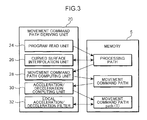
- This computing unit 12 has a movement command path deriving unit 20 and a moving distance calculation unit 22.
- the movement command path deriving unit 20 determines a movement command path path (T) of each movement axis on the basis of the processing path.
- the movement command path path (T) indicates a position for each support 102b, 106a, 108a and 110a which should move in the corresponding movement axis direction as set time T elapses.
- the set time T is time that is set separately from the reference time.
- the movement command path deriving unit 20 has a program read unit 24, a curved surface interpolation unit 26, a movement command path computing unit 28, an acceleration/deceleration computing unit 30, and a local acceleration/deceleration filter 32.
- the program read unit 24 reads a processing path (tool path) from the NC program stored in the storage unit 4.
- the processing path read by the program read unit 24 is stored in the memory 5.
- the curved surface interpolation unit 26 performs interpolation operation if necessary, so that the processing path becomes a smooth path. If the processing path is interpolated by the curved surface interpolation unit 26, this interpolated processing path is stored in the memory 5.
- the movement command path computing unit 28 calculates a movement command path, that is, a movement component in each movement axis direction on the basis of the processing path stored in the memory 5.
- the calculated movement command path in each movement axis direction is stored in the memory 5.
- the acceleration/deceleration computing unit 30 performs calculation of acceleration/deceleration for each movement command path for each movement axis stored in the memory 5, according to the acceleration/deceleration conditions for each movement axis, that is, according to an allowable acceleration and allowable jerk for each movement axis, and calculates a movement command path path (T) for each movement axis as a function of the set time T.
- the calculated movement command path path (T) is stored in the memory 5.
- the local acceleration/deceleration filter 32 interpolates locally and smoothly only the portion, out of the movement command path path (T), indicating a rapid acceleration/deceleration that could cause a mechanical shock to the machine tool.
- the moving distance calculation unit 22 calculates a moving distance of each support 102b, 106a, 108a and 110a in the corresponding movement axis direction per set unit time, depending on whether a special command is inputted to the special command input device 122, and depending on the type of the special command.
- the moving distance calculation unit 22 calculates the deceleration stop period and the stop period unit time change function based on the allowable acceleration and allowable jerk of the movement target object in a combined movement direction of each movement axis direction and set unit time in the state immediately before the input of the emergency stop command, and also calculates a deceleration period set unit time in the deceleration stop period based on the calculated deceleration stop period and stop period unit time change function, and calculates, on the basis of the movement command path path (T), a moving distance of each support 102b, 106a, 108a and 110a in the corresponding movement axis direction per deceleration period set unit time thus calculated respectively.
- T movement command path path
- the moving distance calculation unit 22 calculates accordingly the restart acceleration period and the restart period unit time change function based on the allowable acceleration and the allowable jerk of the movement target object and an override coefficient at the moment of input of the restart command, and calculates the acceleration period set unit time in the calculated restart acceleration period based on the calculated restart acceleration period and the restart period unit time change function, and calculates, on the basis of the command path path (T), the moving distance of each support 102b, 106a, 108a and 110a in the corresponding movement axis direction per acceleration period set unit time thus calculated respectively.
- T command path path
- the moving distance calculation unit 22 calculates accordingly the acceleration period and the acceleration period unit time change function based on the allowable acceleration and the allowable jerk of the movement target object, the set unit time at the moment of the input of the acceleration command, and the acceleration rate (override coefficient) included in the acceleration command, and calculates the acceleration period set unit time during the acceleration period based on the calculated acceleration period and acceleration period unit time change function, and calculates, on the basis of the command path path (T), the moving distance of each support 102b, 106a, 108a and 110a in the corresponding movement axis direction per acceleration period set unit time thus calculated respectively.
- T command path path
- the moving distance calculation unit 22 calculates accordingly the deceleration period and the deceleration period unit time change function based on the allowable acceleration and the allowable jerk of the movement target object, the set unit time at the moment of the input of the deceleration command, and the deceleration rate (override coefficient) included in the deceleration command, and calculates the deceleration period set unit time during the deceleration period based on the calculated deceleration period and deceleration period unit time change function, and calculates, on the basis of the command path path (T), the moving distance of each support 102b, 106a, 108a and 110a in the corresponding movement axis direction per deceleration period set unit time thus calculated respectively.
- T command path path
- the drive control unit 14 causes each driving device 102c, 106b, 108b and 110b to transfer corresponding each support 102b, 106a, 108a or 110a in the corresponding movement axis direction.
- the drive control unit 14 actuates each driving device 102c, 106b, 108b and 110b every time the reference unit time elapses, so as to perform control to cause each driving device 102c, 106b, 108b and 110b to transfer the corresponding support 102b, 106a, 108a or 110a in the corresponding movement axis direction for the amount of the moving distance per set unit time, calculated by the moving distance calculation unit 22 of the computing unit 12.
- the drive control unit 14 executes this control by transmitting a servo command pulse to each driving device 102c, 106b, 108b and 110b.
- the movement command path deriving unit 20 of the computing unit 12 derives the movement command path path (T) for each movement axis on the basis of the processing path (step S2 in Fig. 4 ).
- the data on the derived movement command path path (T) is stored in the memory 5.
- the moving distance calculation unit 22 determines whether data on the movement command path is stored in the memory 5 (step S4). If it is determined that the data on the movement command path is not stored in the memory 5, the moving distance calculation unit 22 performs the determination in step S4 again. If it is determined that the data on the movement command path is stored in the memory 5, on the other hand, the moving distance calculation unit 22 initializes the set time T to 0, and initializes the set unit time ⁇ T to 1 (step S6).
- the moving distance calculation unit 22 initializes a value dg to 0, where the value dg is generated by differentiating the set time function T (t) with the reference time t to acquire a value g(t), and further differentiating this value g(t) with the reference time t (step S8).
- the set time function T (t) indicates a correspondence between the reference time t and the set time T, and expresses the set time T as a function with respect to the reference time t.
- the moving distance calculation unit 22 calculates a unit time moving distance dP [axis] for each movement axis per set unit time ⁇ T using the following Expression (1) respectively (step S10).
- dP axis path T + ⁇ T axis - path T axis
- the moving distance calculation unit 22 calculates the current movement velocity V of the movement target object in the combined movement direction (hereafter called "combined movement velocity V") using the following Expression (2) (step S11).
- the combined movement direction is a direction generated by combining each movement axis direction.
- V dP / ⁇ T
- dP [ ] is a moving distance of the movement target object in the combined movement direction.
- the value of dP [ ] is determined by the moving distance calculation unit 22 combining the unit time moving distance dP [axis] for each movement axis.
- the drive control unit 14 actuates each driving device 102c, 106b, 108b and 110b according to the unit time moving distance dP [axis] calculated by the moving distance calculation unit 22 (step S12).
- the drive control unit 14 creates, for each movement axis, a servo command pulse, which instructs to transfer each support 102b, 106a, 108a and 110ad by the unit time moving distance dP [axis] per reference unit time (1 mm sec. in this embodiment), and outputs the created servo command pulse for each movement axis to the corresponding driving device 102c, 106b, 108b or 110b respectively.
- each driving device 102c, 106b, 108b and 110b transfers the corresponding support 102b, 106a, 108a or 110a for the unit time moving distance dP [axis] per reference unit time, according to the servo command pulse from the drive control unit 14.
- the moving distance calculation unit 22 determines whether processing for all the period of the movement command path path (T) stored in the memory 5 is ended (step S 14).
- the data on the movement command path path (T) stored in the memory 5 is sequentially computed for each set unit time ⁇ T, as mentioned above, and thereby the unit time moving distance dP [axis] is sequentially determined, therefore in step S 14, it is determined whether this computing is ended for all the periods of the movement command path path (T) stored in the memory 5. If the moving distance calculation unit 22 determines that processing is ended for all the periods of the movement command path stored in the memory 5, the numerical control processing by the numerical control apparatus 2 ends.
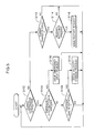
- the acceleration/deceleration request monitoring unit 10 monitors whether a special command is inputted to the special command input device 122 according to the process shown in Fig. 5 .
- the acceleration/deceleration request monitoring unit 10 determines whether the machine tool is in the continuous operation state (step S102). If it is determined that the machine tool is in the continuous operation state, then the acceleration/deceleration request monitoring unit 10 determines whether the emergency stop button 124a is pressed (step S104).
- step S106 If an emergency stop signal transmitted from the stop signal transmission unit 124b is detected and thereby it is determined that and the emergency stop button 124a is pressed, the acceleration/deceleration request monitoring unit 10 issues an emergency stop request (step S106), and then executes the processing in step S52 again. If it is determined that the emergency stop button 124a is not pressed, on the other hand, then the acceleration/deceleration request monitoring unit 10 determines whether the override dial 128a is rotated (step S108).
- step S110 If a velocity change signal transmitted from the velocity change signal transmission unit 128b is detected and thereby it is determined that the override dial 128a is rotated, the acceleration/deceleration request monitoring unit 10 issues a velocity change request which includes information on an override coefficient k according to the rotation direction and rotation amount of the override dial 128a (step S110), then the processing in step S 102 is executed again. If it is determined that the override dial 128a is not rotated, on the other hand, the acceleration/deceleration request monitoring unit 10 executes the processing in step S 102 again, without issuing the velocity change request.
- the acceleration/deceleration request monitoring unit 10 determines whether the transfer of each support 102b, 106a, 108a and 110ad by each driving device 102c, 106b, 108b and 110b is stopping in response to the emergency stop request (step S112).
- the acceleration/deceleration request monitoring unit 10 determines whether the restart button 126a is pressed (step S114). Here, if a restart signal transmitted from the restart signal transmission unit 126b is detected and thereby it is determined that the restart button 126a is pressed, the acceleration/deceleration monitoring unit 10 issues the restart request (step S 116), then executes the processing in step S102 again. If it is determined that the restart button 126a is not pressed, on the other hand, the acceleration/deceleration request monitoring unit 10 executes the processing in step S 102 again without issuing the restart request.
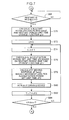
- the moving distance calculation unit 22 determines whether the emergency stop request is issued from the acceleration/deceleration request monitoring unit 10 (step S16 in Fig. 4 ). If it is determined that the emergency stop request is issued, the moving distance calculation unit 22 executes the emergency stop process shown in Fig. 6 .
- the moving distance calculation unit 22 temporarily stores the current value of the combined movement velocity V of the movement target object in the memory 5 (step S22), then calculates the deceleration stop period (time) and the stop period unit time change function g(t) (step S24).
- the moving distance calculation unit 22 calculates the deceleration stop period (time) and the stop period unit time change function g(t) which satisfy the following conditions: a value gs of the stop period unit time change function g(t) in the beginning of the deceleration stop period (time) is the same as the set unit time ⁇ T; a value ge of the stop period unit time change function g(t) in the end of the deceleration stop period (time) is 0; and the combined movement velocity in the beginning of the deceleration stop period (time) is the same as the combined movement velocity V.
- the calculation process of the deceleration stop period (time) and the stop period unit time change function g(t) is shown in Fig. 9. Fig.
- the moving distance calculation unit 22 calculates, in a common calculation process, the period (time) required for the operation involving the velocity change and the unit time change function g(t) which indicates the change of the unit time in this period (time).
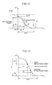
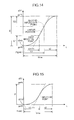
- the stop period unit time change function g(t) is expressed by a curve shown in Fig. 10 , for example. If the movement target object is being accelerated in the beginning of the deceleration stop period (time), the stop period unit time change function g(t) is expressed by a curve shown in Fig. 11 , for example, and if the movement target object is decelerating in the beginning of the deceleration stop period (time), the stop period unit time change function g(t) is expressed by a curve shown in Fig. 12 , for example.
- the moving distance calculation unit 22 To calculate the deceleration stop period (time) and the stop period unit time change function g(t), the moving distance calculation unit 22 first determines a second-order differential value j of the stop period unit time change function g(t), and an inclination a of a first-order differential of the stop period unit time change function g(t) (step S42).
- the second-order differential value j is determined by the following Expression (3)
- the inclination a of the first-order differential is determined by the following Expression (4).
- J denotes an allowable jerk for the movement target object in the combined movement direction
- A denotes an allowable acceleration for the movement target object in the combined movement direction.
- the values of J and A are parameters that are set for calculating (time) and g(t) in this embodiment.
- the value J is set to a value that is about half of the allowable jerk in the acceleration/deceleration conditions specified based on the mechanical characteristics of the machine tool
- the value A is set to a value that is about half of the allowable acceleration in the acceleration/deceleration conditions specified based on the mechanical characteristics of the machine tool.
- the moving distance calculation unit 22 tentatively calculates a relative position (t0, E0) of the peak of the first half portion of the quadratic curve of the stop period unit time change function g(t) with respect to the start point of the stop period unit time change function g(t) in the deceleration stop period (time), using the following Expressions (5) and (6), and tentatively calculates the change amount E of the value of the stop period unit time change function g(t) in a range from the peak of the first half portion of the quadratic curve to the endpoint of the latter half portion of the quadratic curve, using the following Expression (7) (step S50).
- the moving distance calculation unit 22 determines whether the change amount E of the value of the stop period unit time change function g(t) is 0 or more (step S52). If it is determined that the change amount E is 0 or more, the moving distance calculation unit 22 sets the second-order differential value j 1 of the first half portion of the quadratic curve of the stop period unit time change function g(t) to j, and sets the second-order differential value j2 of the latter half portion of the quadratic curve of the stop period unit time change function g(t) to -j (step S54).
- the moving distance calculation unit 22 sets the second-order differential value j1 of the first half portion of the quadratic curve to -j, and sets the second-order differential value j2 of the latter half portion of the quadratic curve to j, and sets the inclination a of the first-order differential of g(t) reversing the + and - signs (step S56).
- the moving distance calculation unit 22 recalculates the relative position (t0, E0) of the peak of the first half portion of the quadratic curve with respect to the start point of the quadratic curve of the stop period unit time change function g(t) using the above Expressions (5) and (6), and recalculates the change amount E of g(t) in a range from the peak of the first half portion of the quadratic curve to the endpoint of the latter half portion, using the above Expression (7) (step S58).
- the moving distance calculation unit 22 calculates the value gu of g(t) at the peak of the first half portion of the quadratic curve of the stop period unit time change function g(t), the time t1 required from the start point to the inflection point of the quadratic curve, the time t2 required from the inflection point to the endpoint of the quadratic curve, the change amount G1 of g(t) in a range from the start point to the inflection point of the quadratic curve, the change amount G2 of g(t) in a range from the inflection point to the endpoint of the quadratic curve, and the change amount G of g(t) in a range from the start point to the endpoint of the quadratic curve respectively (step S60).
- the moving distance calculation unit 22 calculates gu using the following Expression (8), calculates t1 using the following Expression (9), and calculates t2 using the following Expression (10).
- the moving distance calculation unit 22 also calculates G1 using the following Expression (11), calculates G2 using the following Expression (12), and calculates G using the following Expression (13).
- the moving distance calculation unit 22 determines whether the absolute value
- the moving distance calculation unit 22 determines the stop period unit time change function g(t) respectively for three blocks of the quadratic curve: the first half curved portion 0 ⁇ t ⁇ T1; the linear portion T1 ⁇ t ⁇ T2; and the latter half curved portion T2 ⁇ t ⁇ time (step S64).
- the moving distance calculation unit 22 determines the stop period unit time change function g(t) in the 0 ⁇ t ⁇ T1 block using the following Expression (14).
- the moving distance calculation unit 22 determines the stop period unit time change function g(t) in the T1 ⁇ t ⁇ T2 block using the following Expression (15).
- the moving distance calculation unit 22 determines the stop period unit time change function g(t) in the T2 ⁇ t ⁇ time block using the following Expression (16).
- T1 is time required from the start point of the quadratic curve to the first inflection point (endpoint of the first half curved portion), and is determined using the following Expression (17).
- T2 is time required from the start point of the quadratic curve to the second inflection point (endpoint of the linear portion), and is determined using the following Expression (18).
- the deceleration stop period (time) is time required from the start point to the endpoint of the quadratic curve, and is determined using the following Expression (19).
- T ⁇ 1 t ⁇ 0 + t ⁇ 1
- the moving distance calculation unit 22 determines the stop period unit time change function g(t) respectively for two blocks of the quadratic curve: the first half curved portion 0 ⁇ t ⁇ T1; and the latter half curved portion T1 ⁇ t ⁇ time (step S65).
- the moving distance calculation unit 22 determines the stop period unit time change function g(t) in the 0 ⁇ t ⁇ T1 block using the following Expression (20).
- the moving distance calculation unit 22 determines the stop period unit time change function g(t) in the T1 ⁇ t ⁇ time block using the following Expression (21).
- the deceleration stop period (time) is determined using the following Expression (22).
- T1 is time required from the start point to the inflection point (endpoint of the first half curved portion) of the quadratic curve, and is determined using the following Expression (23).
- T ⁇ 1 t ⁇ 0 + t ⁇ 1
- t1 is determined using the following Expression (24), and t2 is determined using the following Expression (25).
- stop period unit time change function g(t) and the deceleration stop period (time) are determined.
- the moving distance calculation unit 22 initially sets the reference time t to 0 (step S26 in Fig. 6 ).
- the moving distance calculation unit 22 increments the reference time t by 1 (step S28), and calculates a deceleration period set unit time dT2, which is a unit time of the set time T in this emergency stop process (deceleration stop period (time)), based on the stop period unit time change function g(t) determined as mentioned above (step S30).
- the length of the deceleration period set unit time dT2 calculated here is less than the length of the set unit time ⁇ T in a state immediately before the emergency stop request is issued from the acceleration/deceleration request monitoring unit 10, that is, a state immediately before pressing the emergency stop button 124a of the stop command input device 124.
- the moving distance calculation unit 22 calculates the deceleration period set unit time dT2 by substituting the reference time t incremented in step S28 in the stop period unit time change function g(t).
- the moving distance calculation unit 22 calculates the moving distance dP [axis] for each movement axis per deceleration period set unit time dT2, that is, the moving distance dP [axis] for each movement axis for the period between the set time T to T + dT2, using the following Expression (27) (step S32).
- dP axis path T + dT ⁇ 2 axis - path T axis
- the moving distance dP [axis] for each movement axis per deceleration period set unit time dT2 determined like this is less than the moving distance for each movement axis per set unit time ⁇ T in the state immediately before the emergency stop request is issued from the acceleration/deceleration request monitoring unit 10.
- step S12 the drive control unit 14 actuates each driving device 102c, 106b, 108b and 110b according to the moving distance dP [axis] for each movement axis per deceleration period set unit time dT2 calculated by the moving distance calculation unit 22, and thereby causes the driving device 102c, 106b, 108b and 110b to transfer the corresponding support 102b, 106a, 108a or 110a for the moving distance dP [axis] for the corresponding movement axis per reference unit time (step S34).
- the moving distance calculation unit 22 updates the set time T by adding the deceleration period set unit time dT2 calculated in step S30 to the set time T (step S36).
- the moving distance calculation unit 22 determines whether the reference time t is not less than the deceleration stop period (time) (step S38). If the reference time t is not less than the deceleration stop period (time), the movement of the movement target object has already been stopped. If it is determined that the reference time t is not less than the deceleration stop period (time), the moving distance calculation unit 22 reads the value of the combined movement velocity V stored in the memory 5 (step S40). If the restart command is inputted to the restart command input device 126 thereafter, the restart process to restart movement of the movement target object (see Fig. 7 ) is executed. If it is determined that the reference time t does not exceed the deceleration stop period (time) in step S38, on the other hand, the moving distance calculation unit 22 executes step S28 and later processing again.
- the moving distance calculation unit 22 determines whether the restart request is outputted from the acceleration/deceleration request monitoring unit 10 (step S68). If it is determined that the restart request is not outputted from the acceleration/deceleration request monitoring unit 10, the moving distance calculation unit 22 repeatedly executes the determination in step S68. If it is determined that the restart request is outputted from the acceleration/deceleration request monitoring unit 10, on the other hand, then the moving distance calculation unit 22 calculates the restart acceleration period (time) and the restart period unit time change function g(t) (step S70).
- the moving distance calculation unit 22 calculates the restart acceleration period (time) and the restart period unit time change function g(t) which satisfy the following conditions: a value gs of the restart period unit time change function g(t) in the beginning of the restart acceleration period (time) is 0; a value ge of the restart period unit time change function g(t) in the end of the restart acceleration period (time) is the same as the override coefficient k at this point; and the combined movement velocity in the end of the restart acceleration period (time) is the same as the combined movement velocity V.
- the calculation process of the restart acceleration period (time) and the restart period unit time change function g(t) is the same as the above mentioned calculation process of the deceleration stop period (time) and the stop period unit time change function g(t) (steps S42 to S65 in Fig. 9 ).
- both t0 and E0 are 0, and dg is 0.
- the restart period unit time change function g(t) is expressed by a curve shown in Fig. 14 , where a linear portion exists between the first half curved portion and the latter half curved portion, and if the absolute value
- step S76 the moving distance calculation unit 22 calculates the acceleration period set unit time dT2 based on the restart period unit time change function g(t) calculated in step S70
- step S78 the moving distance calculation unit 22 calculates the moving distance dP [axis] for each movement axis per acceleration period set unit time dT2 calculated above.
- step S84 If it is determined that the reference time t is not less than the restart acceleration period (time) in step S84, the moving distance calculation unit 22 executes step S8 and later processing in Fig. 4 again.
- the moving distance calculation unit 22 determines whether the velocity change request is issued from the acceleration/deceleration request monitoring unit 10 thereafter (step S 18).
- the moving distance calculation unit 22 executes the velocity change process for the movement target object shown in Fig. 8 .
- the moving distance calculation unit 22 calculates the velocity change period (time) and the velocity change period unit time change function g(t) (step S86).
- the moving distance calculation unit 22 calculates the acceleration change period (time) and the acceleration change period unit time change function g(t) which satisfy the following conditions: a value gs of the velocity change period unit time change function g(t) in the beginning of the velocity change period (time) is the same as the set unit time ⁇ T; a value ge of the velocity change period unit time change function g(t) in the end of the velocity change period (time) is the same as the override coefficient k after the velocity is changed; and the combined movement velocity in the beginning of the velocity change period (time) is the same as the combined movement velocity V.
- the velocity change period (time) is included in the concept of the acceleration period of the present invention if the acceleration command is inputted to the override device 128, and is included in the concept of the deceleration period of the present invention if the deceleration command is inputted to the override device 128.
- the velocity change period unit time change function g(t) is included in the concept of the acceleration period unit time change function of the present invention if the acceleration command is inputted to the override device 128, and is included in the deceleration period unit time change function of the present invention if the deceleration command is inputted to the override device 128.
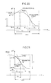
- the velocity change period unit time change function g(t) to accelerate the movement target object is expressed by a curve shown in Fig. 16 , for example. If the movement target object is accelerating in the beginning of the velocity change period (time), the velocity change period unit time change function g(t) to further accelerate the movement target object is expressed by a curve shown in Fig. 17 . If the movement target object is decelerating in the beginning of the velocity change period (time), the velocity change period unit time change function g(t) to decelerate the movement target object is expressed by a curve shown in Fig. 18 .
- the velocity change period unit time change function g(t) to decelerate the movement target object is expressed by a curve shown in Fig. 19 , for example. If the movement target object is accelerating in the beginning of the velocity change period (time), the velocity change period unit time change function g(t) to decelerate the movement target object is expressed by a curve shown in Fig. 20 . If the movement target object is decelerating in the beginning of the velocity change period (time), the velocity change period unit time change function g(t) to further decelerate the movement target object is expressed by a curve shown in Fig. 21 .
- Fig. 16 to Fig. 21 all correspond to the case when the absolute value
- the velocity change period unit time change function g(t) is expressed by a curve where the first half curved portion and the latter half curved portion are connected via a linear portion.
- the moving distance calculation unit 22 After calculating the velocity change period (time) and the velocity change period unit time change function g(t), the moving distance calculation unit 22 sets the reference time t to 0 (step S88), then increments the reference time t by 1 (step S89).
- the moving distance calculation unit 22 calculates the set unit time ⁇ T based on the velocity change period unit time change function g(t) calculated in step S86 (step S90).
- This set unit time ⁇ T is determined by substituting the reference time t incremented in step S89 in the velocity change period unit time change function g(t).
- the moving distance calculation unit 22 calculates, in the same manner as step S 10, the unit time moving distance dP [axis] for each movement axis per set unit time ⁇ T calculated above (step S91).
- the moving distance calculation unit 22 calculates the current combined movement velocity V of the moving target object (step S92).
- the method for calculating the combined movement velocity V is the same as the above mentioned method for calculating the combined movement velocity V in step S 11.
- step S12 the drive control unit 14 actuates each driving device 102c, 106b, 108b and 110b according to the moving distance dP [axis] calculated in step S91 (step S93). Then the moving distance calculation unit 22 updates the set time T by adding the set unit time ⁇ T calculated in step S90 to the set time T (step S94).
- the moving distance calculation unit 22 calculates dg by differentiating the velocity change period unit time change function g(t) determined in step S86 by the reference time t (step S95).
- the moving distance calculation unit 22 determines whether the reference time t is not less than the velocity change period (time). If it is determined that the reference time t is not less than the velocity change period (time), the moving distance calculation unit 22 executes the process in step S8 and later again. If it is determined that the reference time t does not elapse the velocity change period (time), on the other hand, then the moving distance calculation unit 22 determines, in the same manner as step S16, whether the emergency stop request is issued from the acceleration/deceleration request monitoring unit 10 (step S97).
- step S98 the moving distance calculation unit 22 determines here that the velocity change request is issued from the acceleration/deceleration request monitoring unit 10
- step S86 the velocity change process in step S86 and later is executed again. If the moving distance calculation unit 22 determines that the velocity change request is not issued from the acceleration/deceleration request monitoring unit 10, on the other hand, the process in step S89 and later is executed again.
- step S 18 If it is determined that the velocity change request is not issued from the acceleration/deceleration request monitoring unit 10 in step S 18, the moving distance calculation unit 22 updates the set time T by adding the set unit time ⁇ T to the set time T (step S20). Then the process in step S 10 and later is executed again.
- the transfer device 102, 106, 108 or 110 executes irregular operation involving velocity change of the movement target object (emergency stop, acceleration after restart, and acceleration/deceleration of the movement target object during movement)
- the length of the set unit time which is common for each movement axis direction, is changed from the length in a state immediately before the input of the special command to the special command input device 122 to the length corresponding to the velocity change instructed by the special command, and each support 102b, 106a, 108a and 110a is transferred in accordance with the moving distance in the corresponding movement axis direction of each support 102b, 106a, 108a and 110a per set unit time after the change calculated on the basis of the processing path.
- the moving distance of each support 102b, 106a, 108a and 110a in each movement axis direction per set unit time after the change calculated on the basis of the processing path is a moving distance maintaining a relative positional relationship of positions in each movement axis direction specified by the processing path, and each support 102b, 106a, 108a and 110a is transferred for the moving distance in a state maintaining the relative positional relationship among positions in each movement axis direction specified by the processing path.
- each transfer device 102, 106, 108 and 110 executes the operation involving the irregular velocity change of the movement target object (emergency stop, acceleration after restart, and acceleration/deceleration of the movement target object during movement) separately from normal transfer of the movement target object performed when the workpiece 100 is processed.
- operation involving irregular velocity change of the movement target object can be executed, while preventing deviation of the movement locus of the movement target object from the processing path, simply by changing the length of the set unit time common to each movement axis direction, without performing complicated operation when a special command is inputted to the special command input device 122, unlike the case of the technique disclosed in Patent Document 1, which separately performs an operation to cancel an error generated by the acceleration/deceleration after interpolation, or the technique disclosed in Patent Document 2, which performs an acceleration/deceleration operation before interpolation.
- responsiveness from instructing the operation involving the velocity change of the movement target object by the input of a special command to the special command input device 122 to actual execution of this operation of the movement target object by each transport device, 102, 106, 108 and 110, can be improved.
- the responsiveness, from the input of the emergency stop command to the stop command input device to each transfer device 102, 106, 108 and 110 urgently stopping the movement of the movement target object can be improved.
- the responsiveness, from the input of the restart command to the restart command input device 126 to each transfer device 102, 106, 108 and 110 actually restarting the movement of the movement target object can also be improved.
- the responsiveness, from the input of the velocity change command to the override device 128 to each transfer device 102, 106,108 and 110 actually accelerating or decelerating the movement of the movement target object can be improved.
- a set time and a set unit time which are different from the reference time and the reference unit time to be the reference of actuating of the driving devices 102c, 106b, 108b and 110b, are set, and a moving distance of each support 102b, 106a, 108a and 110a in the corresponding movement axis direction per that set unit time is calculated on the basis of the processing path, and thereby the moving distance to move each support 102b, 106a, 108a or 110a per reference unit time is calculated.
- the moving distance of each support 102b, 106a, 108a and 110a per reference unit time, for executing irregular operation involving velocity change of the movement target object is calculated without influencing the reference time and reference unit time to be the reference of actuating of the driving devices 102c, 106b, 108b and 110b. Therefore, operation of the movement target object involving the irregular velocity change can be executed without influencing normal driving by each driving device 102c, 106b, 108b and 110b.
- the numerical control apparatus of the present invention may be applied to machine tools other than the machine tool described in the above embodiment.
- the movement command path deriving unit may not necessarily include the interpolation computing unit and the acceleration/deceleration filter.
- the moving distance calculation unit may calculate the moving distance of each support in the corresponding movement axis direction per set unit time based on the movement command path for each movement axis which the movement command path deriving unit derived without performing the interpolation operation on the basis of the processing path of the processing command program.
- control of the transfer device by the numerical control apparatus of the present invention need not be applicable to all deceleration at emergency stop of the movement target object, acceleration at restart and acceleration/deceleration according to an override device.
- control of the transfer device by the numerical control apparatus of the present invention may be applied only to deceleration of the movement target object at emergency stop, or control of the transfer device by the numerical control apparatus of the present invention may be applied only to acceleration at restart of the movement target object, or control of the transfer device by the numerical control apparatus of the present invention may be applied only to acceleration/deceleration of the movement target object according to an override device.
- the control of the transfer device by the numerical control apparatus of the present invention may be applied to any two of the following three: deceleration of the movement target object at emergency stop; acceleration at restart; and acceleration/deceleration according to an override device.
- the device to indicate the operation involving the velocity change of the movement target object to which control by the numerical control apparatus of the present invention is applied, out of the stop signal input device, restart signal input device and override device, is included in the special command input device of the present invention.
- the numerical control apparatus is a numerical control apparatus installed in a machine tool which includes: a plurality of transfer devices which transfer a movement target object, which is a workpiece or a tool to process the workpiece, when the workpiece is processed; and a special command input device for inputting, from outside, a special command for instructing an operation involving a velocity change of the movement target object separately from normal transfer of the movement target object performed when the workpiece is processed, each of the transfer devices including a support for supporting the movement target object, and a driving device which transfers the movement target object by transferring the support in a predetermined movement axis direction, the numerical control apparatus performing numerical control of each of the transfer devices and including: a storage unit which stores a processing command program which specifies a processing path to indicate a path where the movement target object is to move as a reference time elapses when the workpiece is processed; a computing unit which calculates, on the basis of the processing path, a moving distance of each support in the corresponding movement axis direction per set unit time;
- this numerical control apparatus when the machine tool executes irregular operation involving velocity change of the movement target object, in response to a special command inputted to the special command input device, the length of the set unit time, which is common for each movement axis direction, is changed from the length in a state immediately before the input of the special command to the length corresponding to the velocity change instructed by the special command, and the moving distance of each support in the corresponding moving axis direction per set unit time of which length has been changed is calculated on the basis of the processing path, and each support is transferred in the corresponding movement direction in accordance with the calculated moving distance. Therefore when an operation involving an irregular velocity change of the movement target object is executed separately from the normal transfer of the movement target object performed when a workpiece is processed, deviation of the movement locus of the movement target object from the processing path can be prevented.
- the moving distance of each support in the corresponding moving axis direction per set unit time calculated on the basis of the processing path is calculated as a moving distance maintaining the relative positional relationship among each movement axis specified by the processing path. Therefore, if the corresponding support is transferred by the driving device in accordance with the calculated moving distance in each moving axis direction per set unit time, the operation involving the velocity change of the movement target object is executed in a state maintaining the relative positional relationship among each movement axis specified by the processing path. As a result, deviation of the movement locus of the movement target object from the processing path can be prevented, even if the above operation involving the irregular velocity change of the movement target object is executed.
- operation involving irregular velocity change of the movement target object can be executed, while preventing deviation of the movement target object from the processing path simply by changing the length of the set unit time, without performing a complicated operation when a special command is inputted to the special command input device, unlike the case of the technique disclosed in Patent Document 1, which separately performs operation to cancel an error generated by the acceleration/deceleration after interpolation, or the technique disclosed in Patent Document 2, which performs acceleration/deceleration operation before interpolation. Therefore, the responsiveness, from instructing the operation involving the velocity change of the movement target object by the input of the special command to the special command input device to actual execution of this operation involving velocity change of the movement target object, can be improved.
- the drive control unit controls operation of each driving device so that the driving device transfers, per reference unit time which is a reference of actuating of the driving device, the corresponding support in the corresponding axis direction for the moving distance per the set unit time calculated by the computing unit, and the computing unit sets the set unit time as a unit time which is different from the reference unit time, and calculates, on the basis of the processing path, the moving distance of each support per set unit time in the corresponding movement axis direction.
- the transfer distance (moving distance) of the corresponding support transferred by each driving device in the corresponding moving axis direction per reference unit time can be calculated, and the transfer of each support in the corresponding moving axis direction in accordance with this transfer distance can be performed, without influencing the reference unit time, which is the reference of actuating of the driving device. Therefore, operation of the movement target object involving the irregular velocity change can be executed without influencing actuating of each driving device.
- the special command input device includes a stop command input device for inputting, as the special command, an emergency stop command for urgently decelerating and stopping movement of the movement target object, and in response to the input of the emergency stop command to the stop command input device, the computing unit calculates the set unit time in a predetermined deceleration stop period, based on a stop period unit time change function, which decreases the length of the set unit time from a length in the state immediately before the input of the emergency stop command to the stop command input device to 0 during the deceleration stop period, and calculates, on the basis of the processing path, the moving distance of each support in the corresponding movement axis direction per set unit time thus calculated.
- the moving distance of each support in the corresponding movement axis direction per set unit time is decreased to 0 during the deceleration stop period, whereby the movement target object can be stopped.
- the length of the set unit time is decreased to 0, and the moving distance of each support in the corresponding movement axis direction per set unit time for the length to decrease to 0, is calculated on the basis of the processing path, therefore when the movement target object is urgently stopped, the responsiveness, from the input of the emergency stop command to the stop command input device to the actual execution of the emergency stop of the movement target object, can be improved, while preventing the deviation of the movement locus of the movement target object from the processing path.
- the special command input device includes a restart command input device for inputting, as the special command, a restart command for restarting and accelerating the movement of the stopping movement target object, and in response to the input of the restart command to the restart command input device after the emergency stop command is inputted to the stop command input device, the computing unit calculates the set unit time in a predetermined restart acceleration period on the basis of a restart period unit time change function, which increases the length of the set unit time from 0 to a predetermined length during the restart acceleration period, and calculates, on the basis of the processing path, the moving distance of each support in the corresponding movement axis direction per set unit time thus calculated.
- the moving distance of each support in the corresponding movement axis direction per set unit time is increased from 0 to the specified moving distance as the unit time increases during the restart acceleration period, whereby the restart involving acceleration of the movement target object can be executed.
- the length of the set unit time is increased from 0 to the specified length, and the moving distance of each support in the corresponding movement axis direction per set unit time for the length to increase, is calculated on the basis of the processing path.
- the responsiveness, from the input of the restart command to the restart command input device to the actual execution of the restart and acceleration of the movement target object can be improved, while preventing the deviation of the movement locus of the movement target object from the processing path.
- the special command input device includes a velocity change command input device which can be input, as the special command, an acceleration command which includes an instruction to increase the movement velocity of the movement target object and information on an acceleration rate, which is an increasing rate of the movement velocity, or a deceleration command which includes an instruction to decrease the movement velocity of the movement target object and information on a deceleration rate, which is a decreasing rate of the movement velocity, and in response to the input of the acceleration command to the velocity change command input device, the computing unit calculates the set unit time in a predetermined acceleration period on the basis of an acceleration period unit time change function, which increases the length of the set unit time from a length in the state immediately before the input of the acceleration command to the velocity change command input device to a length corresponding to the acceleration rate included in the acceleration command during the acceleration period, and calculates, on the basis of the processing path, the moving distance of each support in the corresponding movement axis direction per set unit time thus calculated, and in response to the input of the deceler
- acceleration of the movement target object can be executed during the acceleration period by increasing the moving distance of each support in the corresponding movement axis direction per set unit time, from the moving distance per set unit time immediately before the input of the acceleration command to the velocity change command input device to the moving distance according to the acceleration rate included in the acceleration command.
- deceleration of the movement target object can be executed during the deceleration period by decreasing the moving distance of each support in the corresponding movement axis direction per set unit time, from the moving distance per set unit time immediately before the input of the deceleration command to the velocity change command input device to the moving distance according to the deceleration rate included in the deceleration command.
- the set unit time when the acceleration command is inputted to the velocity change command input device, the set unit time is increased and the moving distance of each support in the corresponding movement axis direction per set unit time of which length is increased is calculated on the basis of the processing path, and when the deceleration command is inputted to the velocity change command input device, on the other hand, the set unit time is decreased and the moving distance of each support in the corresponding movement axis direction per set unit time of which length is decreased is calculated on the basis of the processing path, therefore the responsiveness, from the input of the acceleration command or the deceleration command to the velocity change command input device to the actual execution of acceleration or deceleration of the movement target object, can be improved, while preventing deviation of the movement locus of the movement target object from the processing path when the movement velocity of the movement target object when the workpiece is processed is changed in response to the input of the acceleration command or the deceleration command to the velocity change command input device.
Applications Claiming Priority (2)
| Application Number | Priority Date | Filing Date | Title |
|---|---|---|---|
| JP2010171050A JP5331068B2 (ja) | 2010-07-29 | 2010-07-29 | 数値制御装置 |
| PCT/JP2011/004277 WO2012014479A1 (ja) | 2010-07-29 | 2011-07-28 | 数値制御装置 |
Publications (1)
| Publication Number | Publication Date |
|---|---|
| EP2600217A1 true EP2600217A1 (en) | 2013-06-05 |
Family
ID=45529710
Family Applications (1)
| Application Number | Title | Priority Date | Filing Date |
|---|---|---|---|
| EP11812081.5A Withdrawn EP2600217A1 (en) | 2010-07-29 | 2011-07-28 | Numerical control apparatus |
Country Status (5)
| Country | Link |
|---|---|
| US (1) | US20130123968A1 (ja) |
| EP (1) | EP2600217A1 (ja) |
| JP (1) | JP5331068B2 (ja) |
| CN (1) | CN103140817A (ja) |
| WO (1) | WO2012014479A1 (ja) |
Families Citing this family (8)
| Publication number | Priority date | Publication date | Assignee | Title |
|---|---|---|---|---|
| JP5417392B2 (ja) * | 2011-07-29 | 2014-02-12 | 新日本工機株式会社 | 数値制御装置 |
| JP5715189B2 (ja) | 2013-06-12 | 2015-05-07 | ファナック株式会社 | オーバライドの変化時に送り速度を円滑に変更する機能を有する数値制御装置 |
| JP6034835B2 (ja) * | 2014-08-26 | 2016-11-30 | ファナック株式会社 | サイクルタイムを短縮するための情報を提示する数値制御装置 |
| JP6121972B2 (ja) * | 2014-10-22 | 2017-04-26 | ファナック株式会社 | モータ停止距離を短縮する数値制御装置 |
| JP6769219B2 (ja) * | 2016-09-30 | 2020-10-14 | ブラザー工業株式会社 | 数値制御装置 |
| JP6396389B2 (ja) * | 2016-10-27 | 2018-09-26 | ファナック株式会社 | サーボ制御装置 |
| JP6502976B2 (ja) | 2017-02-15 | 2019-04-17 | ファナック株式会社 | 数値制御装置 |
| JP7135407B2 (ja) * | 2018-04-26 | 2022-09-13 | セイコーエプソン株式会社 | 電子時計 |
Family Cites Families (11)
| Publication number | Priority date | Publication date | Assignee | Title |
|---|---|---|---|---|
| US3557461A (en) * | 1967-04-18 | 1971-01-26 | Disk Pack Corp | Mechanical disc pack tester and method |
| JPS63273108A (ja) * | 1987-04-30 | 1988-11-10 | Fanuc Ltd | 速度制御装置 |
| JP2897333B2 (ja) * | 1990-04-11 | 1999-05-31 | ブラザー工業株式会社 | サーボ制御装置 |
| JPH06110532A (ja) * | 1992-09-29 | 1994-04-22 | Intetsuku:Kk | 位置制御方法及び装置 |
| JPH11202915A (ja) * | 1998-01-16 | 1999-07-30 | Fanuc Ltd | 自動機械の制御装置 |
| JP3508677B2 (ja) * | 2000-02-04 | 2004-03-22 | 三菱電機株式会社 | ロボット制御装置 |
| US7035712B2 (en) * | 2002-10-30 | 2006-04-25 | Mitsubishi Denki Kabushiki Kaisha | Numerical control device |
| JP2006004275A (ja) * | 2004-06-18 | 2006-01-05 | Fanuc Ltd | 数値制御装置 |
| JP4796936B2 (ja) * | 2006-11-01 | 2011-10-19 | 株式会社ソディック | 加工制御装置 |
| JP5009010B2 (ja) | 2007-03-13 | 2012-08-22 | 新日本工機株式会社 | 数値制御装置 |
| JP5129064B2 (ja) | 2008-08-26 | 2013-01-23 | 新日本工機株式会社 | 工作機械の数値制御装置 |
-
2010
- 2010-07-29 JP JP2010171050A patent/JP5331068B2/ja not_active Expired - Fee Related
-
2011
- 2011-07-28 CN CN2011800368997A patent/CN103140817A/zh active Pending
- 2011-07-28 US US13/812,645 patent/US20130123968A1/en not_active Abandoned
- 2011-07-28 EP EP11812081.5A patent/EP2600217A1/en not_active Withdrawn
- 2011-07-28 WO PCT/JP2011/004277 patent/WO2012014479A1/ja active Application Filing
Non-Patent Citations (1)
| Title |
|---|
| See references of WO2012014479A1 * |
Also Published As
| Publication number | Publication date |
|---|---|
| CN103140817A (zh) | 2013-06-05 |
| WO2012014479A1 (ja) | 2012-02-02 |
| JP5331068B2 (ja) | 2013-10-30 |
| US20130123968A1 (en) | 2013-05-16 |
| JP2012032960A (ja) | 2012-02-16 |
Similar Documents
| Publication | Publication Date | Title |
|---|---|---|
| EP2600217A1 (en) | Numerical control apparatus | |
| JP5417392B2 (ja) | 数値制御装置 | |
| US9360849B2 (en) | Numerical control method | |
| US7167772B2 (en) | Machining time calculating apparatus | |
| US9636774B2 (en) | Controller for laser beam machining for controlling approaching operation of machining head | |
| JP4261470B2 (ja) | 制御装置 | |
| JP2001125613A (ja) | 数値制御シミュレーション装置 | |
| JPH1039915A (ja) | 数値制御装置 | |
| JPH11129144A (ja) | Nc工作機械の制御装置 | |
| JP2007000941A (ja) | ネジ切削加工制御方法及びその装置 | |
| WO2014002381A1 (ja) | 数値制御装置 | |
| US10725456B2 (en) | Numerical controller | |
| JP6464135B2 (ja) | 数値制御装置 | |
| JP4451708B2 (ja) | 誤加工防止装置および誤加工防止方法 | |
| JP7448637B2 (ja) | 工作機械の制御装置、制御システム、及び制御方法 | |
| US9740196B2 (en) | Numerical controller for controlling drilling operation | |
| JPH0752365B2 (ja) | 数値制御装置 | |
| JP4982170B2 (ja) | 加工制御装置および加工制御プログラム | |
| JPH07210225A (ja) | 数値制御装置 | |
| US11209793B2 (en) | Controller for machine tool and control system | |
| JP7057312B2 (ja) | 工作機械 | |
| JP6549647B2 (ja) | 数値制御装置 | |
| KR0151016B1 (ko) | 서보 모터의 가감속 제어 방법 | |
| JP2000231412A (ja) | インポジションチェック方法及びその装置 | |
| JP3513840B2 (ja) | 数値制御装置の送り速度制御方法 |
Legal Events
| Date | Code | Title | Description |
|---|---|---|---|
| PUAI | Public reference made under article 153(3) epc to a published international application that has entered the european phase |
Free format text: ORIGINAL CODE: 0009012 |
|
| 17P | Request for examination filed |
Effective date: 20130207 |
|
| AK | Designated contracting states |
Kind code of ref document: A1 Designated state(s): AL AT BE BG CH CY CZ DE DK EE ES FI FR GB GR HR HU IE IS IT LI LT LU LV MC MK MT NL NO PL PT RO RS SE SI SK SM TR |
|
| DAX | Request for extension of the european patent (deleted) | ||
| STAA | Information on the status of an ep patent application or granted ep patent |
Free format text: STATUS: THE APPLICATION HAS BEEN WITHDRAWN |
|
| 18W | Application withdrawn |
Effective date: 20150318 |