EP2599687B1 - Vehicle steering system - Google Patents
Vehicle steering system Download PDFInfo
- Publication number
- EP2599687B1 EP2599687B1 EP12194988.7A EP12194988A EP2599687B1 EP 2599687 B1 EP2599687 B1 EP 2599687B1 EP 12194988 A EP12194988 A EP 12194988A EP 2599687 B1 EP2599687 B1 EP 2599687B1
- Authority
- EP
- European Patent Office
- Prior art keywords
- angle
- unit
- motor
- rotation
- rotor
- Prior art date
- Legal status (The legal status is an assumption and is not a legal conclusion. Google has not performed a legal analysis and makes no representation as to the accuracy of the status listed.)
- Not-in-force
Links
- 230000007257 malfunction Effects 0.000 claims description 41
- 230000007246 mechanism Effects 0.000 claims description 16
- 230000008859 change Effects 0.000 claims description 5
- 238000006243 chemical reaction Methods 0.000 description 77
- 230000007274 generation of a signal involved in cell-cell signaling Effects 0.000 description 12
- 238000001514 detection method Methods 0.000 description 10
- 238000010586 diagram Methods 0.000 description 8
- 230000006870 function Effects 0.000 description 6
- 238000009825 accumulation Methods 0.000 description 3
- 238000013459 approach Methods 0.000 description 3
- 230000005856 abnormality Effects 0.000 description 2
- 230000008878 coupling Effects 0.000 description 2
- 238000010168 coupling process Methods 0.000 description 2
- 238000005859 coupling reaction Methods 0.000 description 2
- 230000015654 memory Effects 0.000 description 2
- 238000012545 processing Methods 0.000 description 2
- 230000004044 response Effects 0.000 description 2
- 230000006698 induction Effects 0.000 description 1
- 238000013178 mathematical model Methods 0.000 description 1
- 238000000034 method Methods 0.000 description 1
- 238000012544 monitoring process Methods 0.000 description 1
- 230000000717 retained effect Effects 0.000 description 1
- 238000012546 transfer Methods 0.000 description 1
Images


Classifications
-
- B—PERFORMING OPERATIONS; TRANSPORTING
- B62—LAND VEHICLES FOR TRAVELLING OTHERWISE THAN ON RAILS
- B62D—MOTOR VEHICLES; TRAILERS
- B62D6/00—Arrangements for automatically controlling steering depending on driving conditions sensed and responded to, e.g. control circuits
-
- B—PERFORMING OPERATIONS; TRANSPORTING
- B62—LAND VEHICLES FOR TRAVELLING OTHERWISE THAN ON RAILS
- B62D—MOTOR VEHICLES; TRAILERS
- B62D5/00—Power-assisted or power-driven steering
- B62D5/001—Mechanical components or aspects of steer-by-wire systems, not otherwise provided for in this maingroup
-
- B—PERFORMING OPERATIONS; TRANSPORTING
- B62—LAND VEHICLES FOR TRAVELLING OTHERWISE THAN ON RAILS
- B62D—MOTOR VEHICLES; TRAILERS
- B62D5/00—Power-assisted or power-driven steering
- B62D5/04—Power-assisted or power-driven steering electrical, e.g. using an electric servo-motor connected to, or forming part of, the steering gear
- B62D5/0457—Power-assisted or power-driven steering electrical, e.g. using an electric servo-motor connected to, or forming part of, the steering gear characterised by control features of the drive means as such
- B62D5/046—Controlling the motor
-
- B—PERFORMING OPERATIONS; TRANSPORTING
- B62—LAND VEHICLES FOR TRAVELLING OTHERWISE THAN ON RAILS
- B62D—MOTOR VEHICLES; TRAILERS
- B62D5/00—Power-assisted or power-driven steering
- B62D5/04—Power-assisted or power-driven steering electrical, e.g. using an electric servo-motor connected to, or forming part of, the steering gear
- B62D5/0457—Power-assisted or power-driven steering electrical, e.g. using an electric servo-motor connected to, or forming part of, the steering gear characterised by control features of the drive means as such
- B62D5/0481—Power-assisted or power-driven steering electrical, e.g. using an electric servo-motor connected to, or forming part of, the steering gear characterised by control features of the drive means as such monitoring the steering system, e.g. failures
- B62D5/049—Power-assisted or power-driven steering electrical, e.g. using an electric servo-motor connected to, or forming part of, the steering gear characterised by control features of the drive means as such monitoring the steering system, e.g. failures detecting sensor failures
Definitions
- the invention relates to a vehicle steering system in which an operating member that is operated for steering is not mechanically coupled to a steering mechanism and the steering mechanism is driven by a steered system motor.
- a steer-by-wire system in which a steering wheel that serves as an operating member is not mechanically coupled to a steering mechanism, a steering angle of the steering wheel is detected by an angle sensor, and the driving force of a steered system motor that is controlled on the basis of an output from the angle sensor is transmitted to the steering mechanism.
- the steering wheel because there is no mechanical coupling between the steering wheel and the steering mechanism, it is possible to prevent upthrust of the steering wheel in the event of a collision of a vehicle, and it is also possible to simplify the configuration of the steering mechanism and reduce the weight of the steering mechanism.
- the flexibility in arrangement of the steering wheel increases, and, furthermore, a lever, a pedal, or the like, may be used as the operating member instead of the steering wheel.
- the steering wheel and the steering mechanism are not mechanically coupled to each other. Therefore, if a malfunction occurs in electrical devices such as the steered system motor and sensors necessary to control the steered system motor, it is not possible to execute steering control.
- the sensors necessary to control the steered system motor include a rotation angle sensor used to detect the rotation angle of the steered system motor.
- each kind of electrical device is provided in plurality, and when a malfunction occurs in one of the electrical devices, another electrical device of the same kind with no malfunction is used instead of the malfunctioning electrical device, thereby avoiding the situation where steering is disabled.
- this configuration results in a cost increase because each kind of electrical device needs to be provided in plurality.
- a vehicle steering system having the features of the preamble of claim 1 is known from DE 100 38 167 A1 .
- JP 2007 118823 A discloses an electric power steering control device having a selecting means to select the motor rotating angle sensed by a rotating angle sensing means when a failure sensing means senses no failure in the motor rotating angle sensing means, and selects the motor rotating angle presumed by a presuming means when the failure sensing means senses a failure in the motor rotating angle sensing means.
- EP 1 839 995 A2 discloses an electric power steering device that can detect the abnormality of a steering angle sensor, wherein a steering angular velocity is estimated from the induced voltage of the motor.
- JP 2010 178546 A relates to a power steering apparatus having a brushless motor and no rotating angle sensor, wherein in one mode a rotating angle of the motor rotor is estimated by operation of an induction voltage estimation unit.
- JP 2011 015594 A discloses a power steering apparatus wherein a sensor failure determining part detects abnormality of an output signal of a rotation angle sensor.
- An aspect of the invention relates to a vehicle steering system in which an operating member that is operated for steering is not mechanically coupled to a steering mechanism and the steering mechanism is driven by a steered system motor formed of a brushless motor.
- the vehicle steering system includes: a rotation angle sensor used to detect a rotation angle of a rotor of the steered system motor; a rotor angle estimator that estimates the rotation angle of the rotor of the steered system motor based on an induced voltage of the steered system motor; a target rotor angle computation unit that computes a target rotor angle ( ⁇ SM *) that is a target value of the rotation angle of the rotor of the steered system motor based on a steering state; a signal superimposing unit used to superimpose a rotation maintaining command signal for continuously rotating the steered system motor on the target rotor angle computed by the target rotor angle computation unit; a malfunction detector that detects occurrence of a malfunction of the rotation angle sensor; and a selector.
- the selector changes a control mode from a first control mode, in which the steered system motor is controlled based on the target rotor angle computed by the target rotor angle computation unit or the target rotor angle on which the rotation maintaining command signal has been superimposed by the signal superimposing unit and a value detected by the rotation angle sensor, to a second control mode, in which the steered system motor is controlled based on the target rotor angle on which the rotation maintaining command signal has been superimposed by the signal superimposing unit and the rotation angle of the rotor, which is estimated by the rotor angle estimator.
- motor control is executed in the first control mode. That is, the steered system motor is controlled on the basis of the target rotor angle computed by the target rotor angle computation unit or the target rotor angle on which the rotation maintaining command signal has been superimposed by the signal superimposing unit and the value detected by the rotation angle sensor.
- motor control is executed in the second control mode. That is, the steered system motor is controlled on the basis of the target rotor angle on which the rotation maintaining command signal has been superimposed by the signal superimposing unit and the rotation angle of the rotor, which is estimated by the rotor angle estimator.
- the rotor angle estimator estimates the rotation angle of the rotor of the steered system motor on the basis of the induced voltage of the steered system motor. Therefore, in order to estimate the rotation angle of the rotor with the use of the rotor angle estimator, the steered system motor needs to be rotating.
- the second control mode because it is possible to continuously rotate the steered system motor irrespective of the target rotor angle computed by the target rotor angle computation unit, it is always possible to estimate the rotation angle of the rotor with the use of the rotor angle estimator. As a result, even when a malfunction occurs in the rotation angle sensor, it is possible to execute steering control based on a steering state without using another rotation angle sensor used to detect the rotation angle of the steered system motor.
- the rotation maintaining command signal may be an alternating-current signal.
- the rotation maintaining command signal may be a sinusoidal signal.
- the rotation maintaining command signal is an alternating-current signal, such as a sinusoidal signal, it is possible to rotate the steered system motor alternately in a forward direction and in a reverse direction, for example, while the target rotor angle computed by the target rotor angle computation unit is constant.
- the vehicle steering system may further include a changing unit that changes at least one of an amplitude and a frequency of the rotation maintaining command signal on the basis of a travelling state of a vehicle.
- the vehicle steering system may further include a vehicle speed detector that detects a vehicle speed.
- the changing unit may be configured to change at least one of the amplitude and the frequency of the rotation maintaining command signal on the basis of the vehicle speed detected by the vehicle speed detector.
- the changing unit may, for example, change at least one of the amplitude and the frequency of the rotation maintaining command signal such that the at least one of the amplitude and the frequency of the rotation maintaining command signal becomes smaller as the vehicle speed becomes higher.
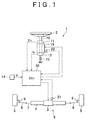
- FIG. 1 shows the configuration of a steer-by-wire system.
- a vehicle steering system 1 includes a steering wheel 2, a steered system motor 3 and a steering gear 4.
- the steering wheel 2 is an operating member that is operated by a driver to steer a vehicle.
- the steered system motor 3 is driven in response to a rotational operation of the steering wheel 2.
- the steering gear 4 transmits the driving force of the steered system motor 3 to right and left front wheels 5 that serve as steered wheels.
- a steering mechanism 6 that includes, for example, the steered system motor 3, there is no mechanical coupling via which steering torque applied to the steering wheel 2 is mechanically transmitted to the steering mechanism 6.
- the wheels 5 are steered by executing drive control of the steered system motor 3 on the basis of an operation amount (steering angle or steering torque) of the steering wheel 2.
- the steered system motor 3 is formed of a brushless motor.
- the steered system motor 3 is provided with a rotation angle sensor 21, such as a resolver, used to detect the rotation angle of a rotor of the steered system motor 3.
- the steering gear 4 has a motion conversion mechanism that converts the rotational motion of an output shaft of the steered system motor 3 into a linear motion (linear motion in the vehicle lateral direction) of a steering rod 7.
- the movement of the steering rod 7 is transmitted to the wheels 5 via tie rods 8 and knuckle arms 9, and the steered angle of the wheels 5 is changed. That is, the steering mechanism 6 is formed of the steered system motor 3, the steering gear 4, the steering rod 7, the tie rods 8 and the knuckle arms 9.
- a known steering gear may be used as the steering gear 4, and the configuration of the steering gear 4 is not limited as long as the movement of the steered system motor 3 is transmitted to the wheels 5 such that the steered angle is changed. Note that, wheel alignment is set such that, in a state where the steered system motor 3 is not driven, the wheels 5 are returned to the straight-ahead steering position by the self-alignment torque.
- the steering wheel 2 is coupled to a rotary shaft 10 that is rotatably supported on the vehicle body side.
- a reaction motor 19 is provided on the rotary shaft 10.
- the reaction motor 19 generates reaction torque (operation reaction force) that acts on the steering wheel 2.
- the reaction motor 19 is formed of an electric motor, such as a brushless motor, that has an output shaft integrated with the rotary shaft 10. In the present embodiment, the reaction motor 19 is formed of a brushless motor.
- the reaction motor 19 is provided with a rotation angle sensor 22, such as a resolver, used to detect the rotation angle (rotor angle) of a rotor of the reaction motor 19.
- An elastic member 15 is provided between the vehicle body and the rotary shaft 10.
- the elastic member 15 applies elastic force in such a direction that the steering wheel 2 is returned to the straight-ahead steering position.
- the elastic member 15 is, for example, formed of a spring that applies elastic force to the rotary shaft 10.
- the vehicle steering system 1 includes an angle sensor 11 that detects the rotation angle of the rotary shaft 10 in order to detect a steering angle (rotation angle) ⁇ h of the steering wheel 2.
- the vehicle steering system 1 includes a torque sensor 12 that is used to detect a torque transmitted by the rotary shaft 10, in order to detect a steering torque Th applied to the steering wheel 2 by a driver.
- the vehicle steering system 1 includes a speed sensor 14 that detects a vehicle speed V.
- the angle sensor 11, the torque sensor 12, the speed sensor 14 and the rotation angle sensors 21, 22 are connected to an electronic control unit (ECU) 30.
- the ECU 30 controls the steered system motor 3 and the reaction motor 19.
- FIG. 2 is a block diagram that shows the electrical configuration of the ECU 30.
- the ECU 30 includes a microcomputer 31, a drive circuit 32, a current detection unit 33, a drive circuit 34 and a current detection unit 35.
- the drive circuit 32 is controlled by the microcomputer 31, and supplies electric power to the steered system motor 3.
- the current detection unit 33 detects motor currents that flow through the steered system motor 3.
- the drive circuit 34 is controlled by the microcomputer 31, and supplies electric power to the reaction motor 19.
- the current detection unit 35 detects motor currents that flow through the reaction motor 19.
- the microcomputer 31 includes a CPU and memories (e.g. a ROM, a RAM, a nonvolatile memory), and functions as a plurality of functional processing units by executing predetermined programs.
- the functional processing units include a steered system motor control unit 40 and a reaction motor control unit 70.
- the steered system motor control unit 40 is used to control the steered system motor 3.
- the reaction motor control unit 70 is used to control the reaction motor 19.
- the steered system motor control unit 40 executes steering control corresponding to a steering state by driving the steered system motor 3 via the drive circuit 32 on the basis of the vehicle speed V detected by the speed sensor 14 and the steering angle ⁇ h detected by the angle sensor 11.
- the reaction motor control unit 70 executes reaction force control corresponding to a steering state by driving the reaction motor 19 via the drive circuit 34 on the basis of the vehicle speed V detected by the speed sensor 14, the steering angle ⁇ h detected by the angle sensor 11 and the steering torque Th detected by the torque sensor 12.
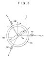
- the steered system motor 3 is, for example, a three-phase brushless motor. As diagrammatically shown in FIG. 3 , the steered system motor 3 includes a rotor 100 and a stator 105. The rotor 100 serves as a field magnet. The stator 105 includes a U-phase stator coil 101, a V-phase stator coil 102 and a W-phase stator coil 103. The steered system motor 3 may be an inner rotor motor in which a stator is arranged radially outward of a rotor such that the stator faces the rotor, or may be an outer rotor motor in which a stator is arranged radially inward of a cylindrical rotor such that the stator faces the rotor.
- a three-phase fixed coordinate system (UVW coordinate system) is defined by setting a U-axis, a V-axis and a W-axis in directions of the U-phase stator coil 101, the V-phase stator coil 102 and the W-phase stator coil 103, respectively.
- a two-phase rotating coordinate system (dq coordinate system, actual rotating coordinate system) is defined by setting a d-axis (magnetic pole axis) in a magnetic pole direction of the rotor 100 and setting a q-axis (torque axis) in a direction that is at right angles to the d-axis within a rotation plane of the rotor 100.
- the dq coordinate system is a rotating coordinate system that rotates together with the rotor 100.
- a d-axis current may be set to zero and the q-axis current may be controlled on the basis of a required torque.
- a rotor angle (electric angle) ⁇ - SE that is the rotation angle of the rotor 100 is a rotation angle of the d-axis with respect to the U-axis.
- the dq coordinate system is an actual rotating coordinate system that rotates in accordance with the rotor angle ⁇ - SE . By using the rotor angle ⁇ - SE , it is possible to execute coordinate conversion between the UVW coordinate system and the dq coordinate system.
- the reaction motor 19 is formed of, for example, a three-phase brushless motor, and has a structure similar to that of the steered system motor 3.
- FIG. 4 is a block diagram that shows the configuration of the steered system motor control unit 40.
- the steered system motor control unit 40 includes a target rotor angle computation unit 41, an addition unit 42, an angle deviation computation unit 43, a proportional-integral (PI) control unit 44, a current command value generation unit 45, a current deviation computation unit 46, a proportional-integral (PI) control unit 47, a dq/UVW conversion unit 48, a pulse width modulation (PWM) control unit 49, a UVW/dq conversion unit 50, a rotation angle computation unit 51, an angle changing unit 52, an accumulation unit 53, an induced voltage estimation unit 54, a rotation angle estimation unit 55, a rotation maintaining command signal generation unit 56 and a sensor malfunction determination unit 57.
- PWM pulse width modulation
- the rotation angle sensor 21 such as a resolver, is provided in order to detect the rotor angle of the steered system motor 3. If a malfunction occurs in the rotation angle sensor 21, it is not possible to detect the rotor angle of the steered system motor 3. Therefore, in the present embodiment, if a malfunction occurs in the rotation angle sensor 21, an induced voltage generated due to the rotation of the steered system motor 3 is estimated, and the rotor angle of the steered system motor 3 is estimated on the basis of the estimated induced voltage. For this purpose, the induced voltage estimation unit 54 and the rotation angle estimation unit 55 are provided. If a malfunction occurs in the rotation angle sensor 21, the steered system motor 3 is controlled using the rotor angle estimated by the rotation angle estimation unit 55.
- the steered system motor 3 In order to estimate an induced voltage, the steered system motor 3 needs to be rotating. Therefore, in the present embodiment, when a malfunction occurs in the rotation angle sensor 21, a rotation maintaining command signal for continuously rotating the steered system motor 3 is superimposed on a target rotor angle of the steered system motor 3. For this purpose, the rotation maintaining command signal generation unit 56 and the addition unit 42 are provided.
- the rotation angle computation unit 51 computes the rotation angle of the rotor of the steered system motor 3 (electric angle; hereinafter, referred to as "first rotor angle ⁇ SE1 ”) on the basis of a signal output from the rotation angle sensor 21.
- the induced voltage estimation unit 54 estimates an induced voltage generated due to the rotation of the steered system motor 3.
- the rotation angle estimation unit 55 estimates the rotation angle of the rotor of the steered system motor 3 (electric angle; hereinafter, referred to as "second rotor angle ⁇ SE2 ”) on the basis of the induced voltage estimated by the induced voltage estimation unit 54.
- second rotor angle ⁇ SE2 The details of operations of the induced voltage estimation unit 54 and rotation angle estimation unit 55 will be described later.
- the angle changing unit 52 selects one of the first rotor angle ⁇ SE1 computed by the rotation angle computation unit 51 and the second rotor angle ⁇ SE2 estimated by the rotation angle estimation unit 55, and outputs the selected rotor angle as a rotor angle (electric angle) ⁇ SE .
- the accumulation unit 53 computes an absolute rotation angle of the rotor of the steered system motor 3 (mechanical angle; hereinafter, referred to as "actual rotor angle ⁇ SM ") by accumulating the rotor angle (electric angle) ⁇ SE output from the angle changing unit 52.
- the sensor malfunction determination unit 57 determines whether there is a malfunction in the rotation angle sensor 21, and changes the control mode of the steered system motor 3 on the basis of the result of determination. That is, the sensor malfunction determination unit 57 functions as a malfunction detector and a selector. For example, the sensor malfunction determination unit 57 is able to detect a malfunction of the rotation angle sensor 21, a break of a signal line of the rotation angle sensor 21 and a ground fault of the signal line of the rotation angle sensor 21, by monitoring a signal output from the rotation angle sensor 21. The sensor malfunction determination unit 57 changes the control mode between a first control mode and a second control mode on the basis of the result of determination as to whether there is a malfunction in the rotation angle sensor 21, and generates a mode changing command. The control mode is changed by the angle changing unit 52 on the basis of the mode changing command.
- the sensor malfunction determination unit 57 sets the control mode to the first control mode "in normal times", that is, when it is determined that there is no malfunction in the rotation angle sensor 21.
- the sensor malfunction determination unit 57 changes the control mode from the first control mode to the second control mode.
- the angle changing unit 52 selects the first rotor angle ⁇ SE1 and outputs the first rotor angle ⁇ SE1 as the rotor angle ⁇ SE .
- the angle changing unit 52 selects the second rotor angle ⁇ SE2 and outputs the second rotor angle ⁇ SE2 as the rotor angle ⁇ SE .
- the mode changing command from the sensor malfunction determination unit 57 is also provided to the rotation maintaining command signal generation unit 56.
- the rotation maintaining command signal generation unit 56 sets the rotation maintaining command signal to zero in the first control mode.
- the mode changing command from the sensor malfunction determination unit 57 is a command to change the control mode from the first control mode to the second control mode
- the rotation maintaining command signal generation unit 56 generates the rotation maintaining command signal (significant value) in response to the command. A method of calculating the rotation maintaining command signal will be described later.
- the target rotor angle computation unit 41 computes a target rotor angle (mechanical angle) ⁇ SM * that is a target value of the rotor angle (mechanical angle) of the steered system motor 3 on the basis of the vehicle speed V detected by the speed sensor 14 and the steering angle ⁇ h detected by the angle sensor 11. For example, the target rotor angle computation unit 41 sets the target rotor angle ⁇ SM * corresponding to the steering angle ⁇ h and the vehicle speed V using a predetermined transfer function K ⁇ (V).
- the addition unit 42 computes a final target rotor angle ⁇ SM1 * (mechanical angle) by adding (superimposing) the rotation maintaining command signal generated by the rotation maintaining command signal generation unit 56 to (on) the target rotor angle ⁇ SM * computed by the target rotor angle computation unit 41.
- the angle deviation computation unit 43 computes a deviation between the final target rotor angle ⁇ SM1 * computed by the addition unit 42 and the actual rotor angle ⁇ SM computed by the accumulation unit 53.
- the PI control unit 44 executes PI computation on the angular deviation computed by the angle deviation computation unit 43.
- the current command value generation unit 45 generates values of currents that should be supplied to coordinate axes of the dq coordinate system, as current command values, on the basis of the result of computation executed by the PI control unit 44. Specifically, the current command value generation unit 45 generates a d-axis current command value I d * and a q-axis current command value I q * (hereinafter, collectively referred to as "two-phase current command values I dq *" where appropriate). The current command value generation unit 45 sets the q-axis current command value I q * to a significant value, and sets the d-axis current command value I d * to zero.
- the current command value generation unit 45 generates the q-axis current command value I q * on the basis of the result of computation executed by the PI control unit 44.
- the two-phase current command values I dq * generated by the current command value generation unit 45 are provided to the current deviation computation unit 46.
- the current detection unit 33 detects a U-phase current I U , V-phase current I V and W-phase current I W of the steered system motor 3 (hereinafter, collectively referred to as "three-phase detected currents I UVW " where appropriate).
- the three-phase detected currents I UVW detected by the current detection unit 33 are provided to the UVW/dq conversion unit 50.
- the UVW/dq conversion unit 50 includes a UVW/ ⁇ conversion unit 50A and an ⁇ /dq conversion unit 50B.
- the UVW/ ⁇ conversion unit 50A converts the three-phase detected currents I UVW of the UVW coordinate system, detected by the current detection unit 33, into two-phase detected currents I ⁇ and I ⁇ (hereinafter, collectively referred to as "two-phase detected currents I ⁇ " where appropriate) of the ⁇ coordinate system that is the two-phase fixed coordinate system.
- the ⁇ coordinate system is a fixed coordinate system in which the rotation center of the rotor 100 is set as an origin and an ⁇ axis and a ⁇ axis (in the example in FIG. 3 , the ⁇ axis coincides with the U-axis) perpendicular to the ⁇ axis are defined within a rotation plane of the rotor 100.
- the ⁇ /dq conversion unit 50B converts the two-phase detected currents I ⁇ into two-phase detected currents I d and Iq of the dp coordinate system (hereinafter, collectively referred to as "two-phase detected currents I dq " where appropriate).
- the two-phase detected currents I dq are provided to the current deviation computation unit 46.
- the rotor angle ⁇ SE selected by the angle changing unit 52 is used for coordinate conversion executed by the ⁇ /dq conversion unit 50B.
- the current deviation computation unit 46 computes a deviation between the two-phase current command values I dq * generated by the current command value generation unit 45 and the two-phase detected currents I dq provided from the ⁇ /dq conversion unit 50B.
- the current deviation computation unit 46 computes a deviation of the d-axis detected current I d from the d-axis current command value I d * and a deviation of the q-axis detected current Iq from the q-axis current command value I q *.
- the deviations are provided to the PI control unit 47.
- the PI control unit 47 generates two-phase voltage command values V dq * (a d-axis voltage command value V d * and a q-axis voltage command value V q *), which are values of voltages that should be applied to the steered system motor 3, by executing PI computation on the current deviations computed by the current deviation computation unit 46.
- the two-phase voltage command values V dq * are provided to the dq/UVW conversion unit 48.
- the dq/UVW conversion unit 48 includes a dq/ ⁇ conversion unit 48A and an ⁇ /UVW conversion unit 48B.
- the dq/ ⁇ conversion unit 48A converts the two-phase voltage command values V dq * into two-phase voltage command values V ⁇ * of the ⁇ coordinate system.
- the rotor angle ⁇ SE selected by the angle changing unit 52 is used for the coordinate conversion.
- the two-phase voltage command values V ⁇ * are formed of an ⁇ -axis voltage command value V ⁇ * and a ⁇ -axis voltage command value V ⁇ *.
- the ⁇ /UVW conversion unit 48B generates three-phase voltage command values V UVW * by executing coordinate conversion computation on the two-phase voltage command values V ⁇ *.
- the three-phase voltage command values V UVW * are formed of a U-phase voltage command value V U *, a V-phase voltage command value V V * and a W-phase voltage command value V W *.
- the three-phase voltage command values V UVW * are provided to the PWM control unit 49.
- the PWM control unit 49 generates a U-phase PWM control signal, a V-phase PWM control signal and a W-phase PWM control signal having duty ratios that correspond to the U-phase voltage command value V U *, the V-phase voltage command value V V * and the W-phase voltage command value V W *, respectively, and supplies the U-phase PWM control signal, the V-phase PWM control signal and the W-phase PWM control signal to the drive circuit 32.
- the drive circuit 32 is formed of a three-phase (corresponding to a U-phase, a V-phase and a W-phase) inverter circuit. Power elements that constitute the inverter circuit are controlled by the PWM control signals provided from the PWM control unit 49. Thus, voltages that correspond to the three-phase voltage command values V UVW * are applied to the respective phase stator coils 101, 102 and 103 of the steered system motor 3.
- the angle deviation computation unit 43 and the PI control unit 44 constitute an angle feedback controller. Due to the function of the angle feedback controller, the actual rotor angle ⁇ SM of the steered system motor 3 is controlled so as to approach the target rotor angle ⁇ SM1 *.
- the current deviation computation unit 46 and the PI control unit 47 constitute a current feedback controller. Due to the function of the current feedback controller, motor currents that flow through the steered system motor 3 are controlled so as to approach the two-phase current command values I dq * generated by the current command value generation unit 45.
- a rotation maintaining command signal generated by the rotation maintaining command signal generation unit 56 is a sinusoidal signal in the present embodiment, and is expressed by Equation 1 indicated below.
- Rotation maintaining command signal K V • sin 2 ⁇ ⁇ • ⁇ V • t
- K(V) is an amplitude control value for setting the amplitude of the rotation maintaining command signal.
- ⁇ (V) is a frequency control value for setting the frequency of the rotation maintaining command signal.
- t is a time.
- Equation 1 the target rotor angle computed by the target rotor angle computation unit 41 .
- the final target rotor angle ⁇ SM1 * computed by the addition unit 42 is expressed by Equation 1 indicated below.
- ⁇ SM ⁇ 1 * ⁇ SM * K V • sin 2 ⁇ ⁇ • ⁇ V • t
- the rotation maintaining command signal generation unit 56 sets the amplitude control value K(V) to zero.
- the rotation maintaining command signal is zero, and therefore the final target rotor angle ⁇ SM1 * is equal to the target rotor angle ⁇ SM * computed by the target rotor angle computation unit 41.
- the rotation maintaining command signal generation unit 56 sets the amplitude control value K(V) to a significant value corresponding to the vehicle speed V, and sets the frequency control value ⁇ (V) to a significant value corresponding to the vehicle speed V.
- the rotation maintaining command signal is superimposed on the target rotor angle ⁇ SM * in order to continuously rotate the steered system motor 3.
- the amplitude control value K(V) is set to a small value (for example, 3 ⁇ /20 ⁇ K(V) ⁇ 16 ⁇ /20).
- the frequency control value ⁇ (V) is set to, for example, a value within a range larger than 0.3 and smaller than 2.0 (0.3 ⁇ ⁇ (V) ⁇ 2.0).
- the amplitude control value K(V) and the frequency control value ⁇ (V) are set so as to be smaller as the vehicle speed V becomes higher.
- the amplitude of the rotation maintaining command signal becomes smaller, and the rotation maintaining command signal changes more moderately. Therefore, when the vehicle speed V is high, the amount of change in the steered angle of the wheels 5 based on the rotation maintaining command signal is small. As a result, stability of steering is ensured.
- the final target rotor angle ⁇ SM1 * is a value obtained by superimposing the rotation maintaining command signal calculated as described above on the target rotor angle ⁇ SM * computed by the target rotor angle computation unit 41.
- FIG. 5 is a time chart that shows an example of changes in the target rotor angle ⁇ SM * and the final target rotor angle ⁇ SM1 * in the second control mode.
- the target rotor angle ⁇ SM * computed by the target rotor angle computation unit 41 remains unchanged, for example, in a retained state
- the final target rotor angle ⁇ SM1 * periodically changes. Therefore, the steered system motor 3 is rotated alternately in the forward direction and in the reverse direction. Therefore, even when the driver is not rotating the steering wheel 2, it is possible to estimate the rotor angle of the steered system motor 3 with the use of the induced voltage estimation unit 54 and the rotation angle estimation unit 55.
- FIG. 6 is a block diagram for illustrating the configuration of the induced voltage estimation unit 54.
- the induced voltage estimation unit 54 estimates the induced voltage of the steered system motor 3 on the basis of the two-phase detected currents I ⁇ and the two-phase voltage command values V ⁇ *.
- the induced voltage estimation unit 54 serves as a disturbance observer that estimates the induced voltage of the steered system motor 3 as a disturbance on the basis of a motor model that is a mathematical model of the steered system motor 3.
- the motor model may be expressed, for example, as (R+pL) -1 .
- R is an armature coil resistance
- L is ⁇ -axis inductances
- p is a differential operator. It is considered that the two-phase voltage command values V ⁇ * and the induced voltages E ⁇ (an ⁇ -axis induced voltage E ⁇ and a ⁇ -axis induced voltage E ⁇ ) are applied to the steered system motor 3.
- the induced voltage estimation unit 54 may be formed of an inverse motor model (inverse model of the motor model) 61 and a voltage deviation computation unit 62.
- the inverse motor model 61 receives the two-phase detected currents I ⁇ and estimates motor voltages.
- the voltage deviation computation unit 62 obtains deviations between the motor voltages estimated by the inverse motor model 61 and the two-phase voltage command values V ⁇ *.
- the voltage deviation computation unit 62 obtains disturbances for the two-phase voltage command values V ⁇ *. As is apparent from FIG.
- the disturbances are estimated values E ⁇ ⁇ (an ⁇ -axis induced voltage estimated value E ⁇ ⁇ and a ⁇ -axis induced voltage estimated value E ⁇ ⁇ (hereinafter, correctively referred to as estimated induced voltages E ⁇ ⁇ )) that correspond to the induced voltages E ⁇ .
- the inverse motor model 61 is expressed by, for example, R + pL.
- the induced voltages E ⁇ may be expressed by Equation 3 indicated below.
- K E is an induced voltage constant
- ⁇ SE is a rotor angle
- ⁇ is a rotor rotation angular velocity.
- K E ⁇ ⁇ ⁇ cos ⁇ ⁇ SE Therefore, when the estimated induced voltages E ⁇ ⁇ are obtained, an estimated rotation angle ⁇ SE2 is obtained according to Equation 4 indicated below. This computation is executed by the rotation angle estimation unit 55.
- ⁇ SE ⁇ 2 tan - 1 ⁇ - E ⁇ ⁇ E ⁇ ⁇
- the steered system motor 3 is controlled using the rotor angle ⁇ SE2 estimated by the rotation angle estimation unit 55 and the target rotor angle ⁇ SM1 * obtained by superimposing the rotation maintaining command signal on the target rotor angle ⁇ SM * computed by the target rotor angle computation unit 41. Therefore, it is possible to continuously rotate the steered system motor 3 irrespective of the target rotor angle ⁇ SM * computed by the target rotor angle computation unit 41. Accordingly, it is always possible to estimate the rotor angle ⁇ SE2 with the use of the induced voltage estimation unit 54 and the rotation angle estimation unit 55.
- the rotation maintaining command signal is a sinusoidal signal, and has a small amplitude. Therefore, it is possible to suppress occurrence of the situation where the driver feels a sense of discomfort.
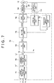
- FIG. 7 is a block diagram that shows the configuration of the reaction motor control unit 70.
- the reaction motor control unit 70 includes a target reaction torque computation unit 71, a current command value generation unit 72, a current deviation computation unit 73, a proportional-integral (PI) control unit 74, a dq/UVW conversion unit 75, a PWM control unit 76, a UVW/dq conversion unit 77 and a rotation angle computation unit 78.
- the rotation angle computation unit 78 computes the rotation angle (electric angle; hereinafter, referred to as "rotor angle ⁇ FE ”) of the rotor of the reaction motor 19 on the basis of the signal output from the rotation angle sensor 22.
- the target reaction torque computation unit 71 computes a target reaction torque T F * on the basis of the vehicle speed V detected by the speed sensor 14, the steering angle ⁇ h detected by the angle sensor 11 and the steering torque Th detected by the torque sensor 12. For example, the target reaction torque computation unit 71 computes the target reaction torque T F * by obtaining a target reaction torque basic value on the basis of the steering angle ⁇ h and the vehicle speed V and then multiplying the target reaction torque basic value by a gain corresponding to the steering torque Th.
- the current command value generation unit 72 generates values of currents that should be supplied to coordinate axes of the dq coordinate system, as current command values, on the basis of the target reaction torque T F * computed by the target reaction torque computation unit 71. Specifically, the current command value generation unit 72 generates a d-axis current command value i d * and a q-axis current command value i q * (hereinafter, collectively referred to as "two-phase current command values i dq *" where appropriate). The current command value generation unit 72 sets the q-axis current command value i q * to a significant value, and sets the d-axis current command value i d * to zero.
- the current command value generation unit 72 generates the q-axis current command value i q * on the basis of the target reaction torque T F * computed by the target reaction torque computation unit 71.
- the two-phase current command values i dq * generated by the current command value generation unit 72 are provided to the current deviation computation unit 73.
- the current detection unit 35 detects a U-phase current i U , V-phase current i V and W-phase current i W (hereinafter, collectively referred to as "three-phase detected currents i UVW " where appropriate) of the reaction motor 19.
- the three-phase detected currents i UVW detected by the current detection unit 35 are provided to the UVW/dq conversion unit 77.
- the UVW/dq conversion unit 77 converts the three-phase detected currents i UVW (U-phase current i U , V-phase current i V and W-phase current i W ) of the UVW coordinate system, detected by the current detection unit 35, into the two-phase detected currents i d and i q (hereinafter, collectively referred to as "two-phase detected currents i dq " where appropriate) of the dq coordinate system.
- the two-phase detected currents i dq are transmitted to the current deviation computation unit 73.
- the rotor angle ⁇ FE computed by the rotation angle computation unit 78 is used for coordinate conversion executed by the UVW/dq conversion unit 77.
- the current deviation computation unit 73 computes a deviation between the two-phase current command values i dq * generated by the current command value generation unit 72 and the two-phase detected currents i dq provided from the UVW/dq conversion unit 77.
- the current deviation computation unit 73 computes a deviation of the d-axis detected current i d from the d-axis current command value i d * and a deviation of the q-axis detected current i q from the q-axis current command value i q *.
- the deviations are provided to the PI control unit 74.
- the PI control unit 74 generates two-phase voltage command values v dq * (a d-axis voltage command value v d * and a q-axis voltage command value v q *), which are values of voltages that should be applied to the reaction motor 19, by executing PI computation on the current deviations computed by the current deviation computation unit 73.
- the two-phase voltage command values v dq * are provided to the dq/UVW conversion unit 75.
- the dq/UVW conversion unit 75 converts the two-phase voltage command values V dq * into three-phase voltage command values v UVW *.
- the rotor angle ⁇ FE computed by the rotation angle computation unit 78 is used for the coordinate conversion.
- the three-phase voltage command values v UVW * are formed of a U-phase voltage command value v U *, a V-phase voltage command value v V * and a W-phase voltage command value v W *.
- the three-phase voltage command values v UVW * are provided to the PWM control unit 76.
- the PWM control unit 76 generates a U-phase PWM control signal, a V-phase PWM control signal and a W-phase PWM control signal having duty ratios respectively corresponding to the U-phase voltage command value v U *, the V-phase voltage command value v V * and the W-phase voltage command value v W *, and supplies the U-phase PWM control signal, the V-phase PWM control signal and the W-phase PWM control signal to the drive circuit 34.
- the drive circuit 34 is formed of a three-phase (corresponding to a U-phase, a V-phase and a W-phase) inverter circuit. Power elements that constitute the inverter circuit are controlled by the PWM control signals provided from the PWM control unit 76. Thus, voltages corresponding to the three-phase voltage command values v UVW * are applied to the respective phase stator coils of the reaction motor 19.
- the current deviation computation unit 73 and the PI control unit 74 constitute a current feedback controller. Due to the function of the current feedback controller, motor currents that flow through the reaction motor 19 are controlled so as to approach the two-phase current command values i dq * generated by the current command value generation unit 72.
- the embodiment of the invention is described above. However, the invention may be implemented in various other embodiment.
- the rotation maintaining command signal generation unit 56 sets the amplitude control value K (V) to zero.
- the rotation maintaining command signal generation unit 56 may set the amplitude control value K (V) to a significant value other than zero as in the above-described case where a sensor malfunction has been detected.
- the target rotor angle ⁇ SM1* obtained by superimposing the rotation maintaining command signal calculated on the basis of the vehicle speed V, on the target rotor angle ⁇ SM * computed by the target rotor angle computation unit 41 is used as a final target rotor angle.
- the amplitude control value K(V) and the frequency control value ⁇ (V) are changed on the basis of the vehicle speed.
- the amplitude control value K(V) and the frequency control value ⁇ (V) may be changed on the basis of a road surface condition, a place where the vehicle is travelling, and the like.
- the rotation maintaining command signal may be an alternating-current signal (triangular-wave alternating-current signal, trapezoidal-wave alternating-current signal, or the like) other than the sinusoidal signal.
- the PI control units 44, 47 and 74 each may be a PID control unit that executes proportional-integral-derivative (PID) control.
Landscapes
- Engineering & Computer Science (AREA)
- Chemical & Material Sciences (AREA)
- Combustion & Propulsion (AREA)
- Transportation (AREA)
- Mechanical Engineering (AREA)
- Control Of Motors That Do Not Use Commutators (AREA)
- Steering Control In Accordance With Driving Conditions (AREA)
- Power Steering Mechanism (AREA)
Applications Claiming Priority (1)
| Application Number | Priority Date | Filing Date | Title |
|---|---|---|---|
| JP2011262348A JP5867782B2 (ja) | 2011-11-30 | 2011-11-30 | 車両用操舵装置 |
Publications (3)
| Publication Number | Publication Date |
|---|---|
| EP2599687A2 EP2599687A2 (en) | 2013-06-05 |
| EP2599687A3 EP2599687A3 (en) | 2014-12-31 |
| EP2599687B1 true EP2599687B1 (en) | 2016-01-20 |
Family
ID=47290702
Family Applications (1)
| Application Number | Title | Priority Date | Filing Date |
|---|---|---|---|
| EP12194988.7A Not-in-force EP2599687B1 (en) | 2011-11-30 | 2012-11-30 | Vehicle steering system |
Country Status (4)
| Country | Link |
|---|---|
| US (1) | US8909429B2 (ja) |
| EP (1) | EP2599687B1 (ja) |
| JP (1) | JP5867782B2 (ja) |
| CN (1) | CN103129606B (ja) |
Families Citing this family (14)
| Publication number | Priority date | Publication date | Assignee | Title |
|---|---|---|---|---|
| JP5711493B2 (ja) * | 2010-09-30 | 2015-04-30 | Thk株式会社 | リニアモータの制御装置、及びリニアモータ装置 |
| US9203332B2 (en) * | 2011-06-30 | 2015-12-01 | Ntn Corporation | Motor drive device |
| US8723470B2 (en) * | 2011-09-30 | 2014-05-13 | The Johns Hopkins University | System and method for determining position of hall sensors relative to stator winding of brushless DC or synchronous AC permanent magnet motor |
| JP5880953B2 (ja) * | 2012-03-22 | 2016-03-09 | 株式会社ジェイテクト | 車両用操舵装置 |
| JP2015160504A (ja) | 2014-02-27 | 2015-09-07 | 株式会社ジェイテクト | 車両用操舵装置、当該装置の故障判定方法、及び転舵モータの制御方法 |
| US9802642B2 (en) * | 2014-04-11 | 2017-10-31 | Steering Solutions Ip Holding Corporation | Phase current measurement diagnostic |
| JP2016136803A (ja) * | 2015-01-23 | 2016-07-28 | 株式会社デンソー | 回転電機の制御システム |
| JP6292208B2 (ja) * | 2015-11-05 | 2018-03-14 | トヨタ自動車株式会社 | ハイブリッド車両 |
| EP3460990B1 (en) * | 2016-07-20 | 2020-04-01 | Nsk Ltd. | Electric power steering device |
| JP6922669B2 (ja) | 2017-11-07 | 2021-08-18 | 株式会社ジェイテクト | 操舵制御装置 |
| JP6911714B2 (ja) | 2017-11-07 | 2021-07-28 | 株式会社ジェイテクト | 操舵制御装置 |
| CN108945091B (zh) * | 2018-07-26 | 2020-03-24 | 北京新能源汽车股份有限公司 | 转向控制方法、装置、电动助力转向系统控制器及汽车 |
| KR102573267B1 (ko) * | 2018-08-27 | 2023-09-01 | 에이치엘만도 주식회사 | 차량 제어 장치 및 방법 |
| DE102018218587A1 (de) * | 2018-10-30 | 2020-04-30 | Audi Ag | Verfahren zum Betreiben eines Lenksystems für ein Kraftfahrzeug sowie entsprechendes Lenksystem |
Family Cites Families (37)
| Publication number | Priority date | Publication date | Assignee | Title |
|---|---|---|---|---|
| JP2959957B2 (ja) * | 1994-06-06 | 1999-10-06 | 本田技研工業株式会社 | 電動パワーステアリング |
| JP3285490B2 (ja) * | 1996-05-28 | 2002-05-27 | 三菱電機株式会社 | 電動式パワーステアリング装置 |
| JP3344463B2 (ja) * | 1998-04-27 | 2002-11-11 | トヨタ自動車株式会社 | 車両用操舵制御装置 |
| DE10038167B4 (de) * | 2000-08-04 | 2006-11-02 | Robert Bosch Gmbh | Steer-By-Wire-Lenkanlage für ein Fahrzeug |
| JP4248739B2 (ja) * | 2000-08-30 | 2009-04-02 | 三菱電機株式会社 | 電動パワーステアリング制御装置及びその制御方法 |
| US6543570B2 (en) * | 2001-07-03 | 2003-04-08 | Trw Inc. | Electric power assisted steering system with friction compensation and method for controlling the system |
| JP2003040119A (ja) * | 2001-07-26 | 2003-02-13 | Koyo Seiko Co Ltd | 車両用操舵装置 |
| JP3946991B2 (ja) * | 2001-12-14 | 2007-07-18 | 株式会社ジェイテクト | 電動パワーステアリング装置の制御装置 |
| JP3812739B2 (ja) * | 2002-05-28 | 2006-08-23 | 三菱電機株式会社 | モータ異常検出装置及び電動パワーステアリング制御装置 |
| JP3933536B2 (ja) * | 2002-07-03 | 2007-06-20 | 株式会社ジェイテクト | 電動パワーステアリング装置 |
| JP4019825B2 (ja) * | 2002-07-09 | 2007-12-12 | 株式会社ジェイテクト | 電動パワーステアリング装置 |
| CN100490302C (zh) * | 2004-03-19 | 2009-05-20 | 三菱电机株式会社 | 电动机控制装置 |
| EP1752359B1 (en) * | 2004-04-30 | 2009-03-18 | NSK Ltd., | Control device of electric power steering device |
| JP4857627B2 (ja) * | 2005-07-07 | 2012-01-18 | 日産自動車株式会社 | 車両用操舵装置及び車両用操舵方法 |
| JP5011705B2 (ja) * | 2005-10-28 | 2012-08-29 | 日本精工株式会社 | 電動パワーステアリング制御装置 |
| JP4957022B2 (ja) * | 2006-03-09 | 2012-06-20 | 日産自動車株式会社 | 車両用操舵制御装置 |
| JP4716118B2 (ja) * | 2006-03-29 | 2011-07-06 | 株式会社ジェイテクト | モータ制御装置 |
| JP5003929B2 (ja) * | 2006-03-29 | 2012-08-22 | 株式会社ジェイテクト | 電動パワーステアリング装置 |
| JP4984598B2 (ja) * | 2006-03-30 | 2012-07-25 | 日本精工株式会社 | 電動パワーステアリング装置 |
| JP4329792B2 (ja) * | 2006-08-10 | 2009-09-09 | トヨタ自動車株式会社 | 電動パワーステアリング装置 |
| US7877179B2 (en) * | 2006-09-12 | 2011-01-25 | GM Global Technology Operations LLC | Mechanical and electrical locking coordination security strategy for an active front steer system |
| JP2008068777A (ja) * | 2006-09-15 | 2008-03-27 | Toyota Motor Corp | 電動パワーステアリング装置 |
| EP1995150A3 (en) * | 2007-05-25 | 2009-05-06 | NSK Ltd. | Electric power steering apparatus |
| JP4760850B2 (ja) * | 2008-04-07 | 2011-08-31 | 三菱電機株式会社 | 電動パワーステアリング装置 |
| JP5286357B2 (ja) * | 2008-05-28 | 2013-09-11 | 本田技研工業株式会社 | 電動ステアリング装置 |
| JP2009298371A (ja) * | 2008-06-17 | 2009-12-24 | Jtekt Corp | 車両用操舵装置 |
| JP5273450B2 (ja) * | 2008-06-24 | 2013-08-28 | 株式会社ジェイテクト | モータ制御装置 |
| JP2010029030A (ja) * | 2008-07-23 | 2010-02-04 | Jtekt Corp | モータ制御装置 |
| JP5218028B2 (ja) * | 2008-12-25 | 2013-06-26 | 日産自動車株式会社 | 車両用操舵制御装置及び車両用操舵制御方法 |
| JP5376214B2 (ja) * | 2009-01-30 | 2013-12-25 | 株式会社ジェイテクト | モータ制御装置 |
| JP5273465B2 (ja) * | 2009-01-30 | 2013-08-28 | 株式会社ジェイテクト | モータ制御装置 |
| JP5376215B2 (ja) * | 2009-01-30 | 2013-12-25 | 株式会社ジェイテクト | モータ制御装置 |
| CN201405922Y (zh) * | 2009-03-13 | 2010-02-17 | 北京工业大学 | 一种汽车线控转向系统 |
| JP5561515B2 (ja) * | 2009-07-06 | 2014-07-30 | 株式会社ジェイテクト | モータ制御装置 |
| JP5561516B2 (ja) * | 2009-07-06 | 2014-07-30 | 株式会社ジェイテクト | モータ制御装置および車両用操舵装置 |
| KR101313935B1 (ko) * | 2009-10-15 | 2013-10-14 | 주식회사 만도 | 조향각 센서 초기화 고장 검출 방법 및 장치 |
| JP5692569B2 (ja) * | 2010-08-23 | 2015-04-01 | 株式会社ジェイテクト | 車両用操舵装置 |
-
2011
- 2011-11-30 JP JP2011262348A patent/JP5867782B2/ja not_active Expired - Fee Related
-
2012
- 2012-11-23 US US13/684,329 patent/US8909429B2/en not_active Expired - Fee Related
- 2012-11-30 CN CN201210505885.1A patent/CN103129606B/zh not_active Expired - Fee Related
- 2012-11-30 EP EP12194988.7A patent/EP2599687B1/en not_active Not-in-force
Also Published As
| Publication number | Publication date |
|---|---|
| CN103129606B (zh) | 2015-11-18 |
| CN103129606A (zh) | 2013-06-05 |
| US20130138300A1 (en) | 2013-05-30 |
| US8909429B2 (en) | 2014-12-09 |
| JP5867782B2 (ja) | 2016-02-24 |
| EP2599687A3 (en) | 2014-12-31 |
| JP2013112279A (ja) | 2013-06-10 |
| EP2599687A2 (en) | 2013-06-05 |
Similar Documents
| Publication | Publication Date | Title |
|---|---|---|
| EP2599687B1 (en) | Vehicle steering system | |
| EP2599686B1 (en) | Vehicle steering system | |
| EP2296264B1 (en) | Motor control device and vehicle-steering device comprising same | |
| EP2177422B1 (en) | Vehicle steering apparatus | |
| US9248852B2 (en) | Electric power steering system | |
| US10272941B2 (en) | Vehicle steering device | |
| EP2907729B1 (en) | Electric Power Steering Apparatus | |
| US8862322B2 (en) | Motor control unit and vehicle steering apparatus | |
| US10293856B2 (en) | Vehicular steering system | |
| US8380398B2 (en) | Motor control unit and motor control unit for vehicle steering apparatus | |
| EP2423074B1 (en) | Vehicle steering system | |
| US8874318B2 (en) | Motor control unit and motor control unit for vehicle steering apparatus | |
| EP2323250B1 (en) | Motor control unit and vehicle steering system | |
| EP2567879B1 (en) | Electric power steering system | |
| EP3480081B1 (en) | Steering control apparatus | |
| CN117561196A (zh) | 自动驾驶辅助装置 |
Legal Events
| Date | Code | Title | Description |
|---|---|---|---|
| PUAI | Public reference made under article 153(3) epc to a published international application that has entered the european phase |
Free format text: ORIGINAL CODE: 0009012 |
|
| AK | Designated contracting states |
Kind code of ref document: A2 Designated state(s): AL AT BE BG CH CY CZ DE DK EE ES FI FR GB GR HR HU IE IS IT LI LT LU LV MC MK MT NL NO PL PT RO RS SE SI SK SM TR |
|
| AX | Request for extension of the european patent |
Extension state: BA ME |
|
| PUAL | Search report despatched |
Free format text: ORIGINAL CODE: 0009013 |
|
| AK | Designated contracting states |
Kind code of ref document: A3 Designated state(s): AL AT BE BG CH CY CZ DE DK EE ES FI FR GB GR HR HU IE IS IT LI LT LU LV MC MK MT NL NO PL PT RO RS SE SI SK SM TR |
|
| AX | Request for extension of the european patent |
Extension state: BA ME |
|
| RIC1 | Information provided on ipc code assigned before grant |
Ipc: B62D 5/00 20060101AFI20141127BHEP Ipc: B62D 5/04 20060101ALI20141127BHEP |
|
| 17P | Request for examination filed |
Effective date: 20150615 |
|
| RBV | Designated contracting states (corrected) |
Designated state(s): AL AT BE BG CH CY CZ DE DK EE ES FI FR GB GR HR HU IE IS IT LI LT LU LV MC MK MT NL NO PL PT RO RS SE SI SK SM TR |
|
| GRAP | Despatch of communication of intention to grant a patent |
Free format text: ORIGINAL CODE: EPIDOSNIGR1 |
|
| INTG | Intention to grant announced |
Effective date: 20151009 |
|
| GRAS | Grant fee paid |
Free format text: ORIGINAL CODE: EPIDOSNIGR3 |
|
| GRAA | (expected) grant |
Free format text: ORIGINAL CODE: 0009210 |
|
| AK | Designated contracting states |
Kind code of ref document: B1 Designated state(s): AL AT BE BG CH CY CZ DE DK EE ES FI FR GB GR HR HU IE IS IT LI LT LU LV MC MK MT NL NO PL PT RO RS SE SI SK SM TR |
|
| REG | Reference to a national code |
Ref country code: GB Ref legal event code: FG4D |
|
| REG | Reference to a national code |
Ref country code: CH Ref legal event code: EP |
|
| REG | Reference to a national code |
Ref country code: IE Ref legal event code: FG4D |
|
| REG | Reference to a national code |
Ref country code: AT Ref legal event code: REF Ref document number: 771566 Country of ref document: AT Kind code of ref document: T Effective date: 20160215 |
|
| REG | Reference to a national code |
Ref country code: DE Ref legal event code: R096 Ref document number: 602012014074 Country of ref document: DE |
|
| REG | Reference to a national code |
Ref country code: LT Ref legal event code: MG4D Ref country code: NL Ref legal event code: MP Effective date: 20160120 |
|
| REG | Reference to a national code |
Ref country code: AT Ref legal event code: MK05 Ref document number: 771566 Country of ref document: AT Kind code of ref document: T Effective date: 20160120 |
|
| PG25 | Lapsed in a contracting state [announced via postgrant information from national office to epo] |
Ref country code: NL Free format text: LAPSE BECAUSE OF FAILURE TO SUBMIT A TRANSLATION OF THE DESCRIPTION OR TO PAY THE FEE WITHIN THE PRESCRIBED TIME-LIMIT Effective date: 20160120 |
|
| PG25 | Lapsed in a contracting state [announced via postgrant information from national office to epo] |
Ref country code: FI Free format text: LAPSE BECAUSE OF FAILURE TO SUBMIT A TRANSLATION OF THE DESCRIPTION OR TO PAY THE FEE WITHIN THE PRESCRIBED TIME-LIMIT Effective date: 20160120 Ref country code: IT Free format text: LAPSE BECAUSE OF FAILURE TO SUBMIT A TRANSLATION OF THE DESCRIPTION OR TO PAY THE FEE WITHIN THE PRESCRIBED TIME-LIMIT Effective date: 20160120 Ref country code: NO Free format text: LAPSE BECAUSE OF FAILURE TO SUBMIT A TRANSLATION OF THE DESCRIPTION OR TO PAY THE FEE WITHIN THE PRESCRIBED TIME-LIMIT Effective date: 20160420 Ref country code: HR Free format text: LAPSE BECAUSE OF FAILURE TO SUBMIT A TRANSLATION OF THE DESCRIPTION OR TO PAY THE FEE WITHIN THE PRESCRIBED TIME-LIMIT Effective date: 20160120 Ref country code: ES Free format text: LAPSE BECAUSE OF FAILURE TO SUBMIT A TRANSLATION OF THE DESCRIPTION OR TO PAY THE FEE WITHIN THE PRESCRIBED TIME-LIMIT Effective date: 20160120 Ref country code: GR Free format text: LAPSE BECAUSE OF FAILURE TO SUBMIT A TRANSLATION OF THE DESCRIPTION OR TO PAY THE FEE WITHIN THE PRESCRIBED TIME-LIMIT Effective date: 20160421 |
|
| PG25 | Lapsed in a contracting state [announced via postgrant information from national office to epo] |
Ref country code: LV Free format text: LAPSE BECAUSE OF FAILURE TO SUBMIT A TRANSLATION OF THE DESCRIPTION OR TO PAY THE FEE WITHIN THE PRESCRIBED TIME-LIMIT Effective date: 20160120 Ref country code: SE Free format text: LAPSE BECAUSE OF FAILURE TO SUBMIT A TRANSLATION OF THE DESCRIPTION OR TO PAY THE FEE WITHIN THE PRESCRIBED TIME-LIMIT Effective date: 20160120 Ref country code: LT Free format text: LAPSE BECAUSE OF FAILURE TO SUBMIT A TRANSLATION OF THE DESCRIPTION OR TO PAY THE FEE WITHIN THE PRESCRIBED TIME-LIMIT Effective date: 20160120 Ref country code: PT Free format text: LAPSE BECAUSE OF FAILURE TO SUBMIT A TRANSLATION OF THE DESCRIPTION OR TO PAY THE FEE WITHIN THE PRESCRIBED TIME-LIMIT Effective date: 20160520 Ref country code: PL Free format text: LAPSE BECAUSE OF FAILURE TO SUBMIT A TRANSLATION OF THE DESCRIPTION OR TO PAY THE FEE WITHIN THE PRESCRIBED TIME-LIMIT Effective date: 20160120 Ref country code: AT Free format text: LAPSE BECAUSE OF FAILURE TO SUBMIT A TRANSLATION OF THE DESCRIPTION OR TO PAY THE FEE WITHIN THE PRESCRIBED TIME-LIMIT Effective date: 20160120 Ref country code: RS Free format text: LAPSE BECAUSE OF FAILURE TO SUBMIT A TRANSLATION OF THE DESCRIPTION OR TO PAY THE FEE WITHIN THE PRESCRIBED TIME-LIMIT Effective date: 20160120 Ref country code: IS Free format text: LAPSE BECAUSE OF FAILURE TO SUBMIT A TRANSLATION OF THE DESCRIPTION OR TO PAY THE FEE WITHIN THE PRESCRIBED TIME-LIMIT Effective date: 20160520 |
|
| REG | Reference to a national code |
Ref country code: FR Ref legal event code: PLFP Year of fee payment: 5 |
|
| REG | Reference to a national code |
Ref country code: DE Ref legal event code: R097 Ref document number: 602012014074 Country of ref document: DE |
|
| PG25 | Lapsed in a contracting state [announced via postgrant information from national office to epo] |
Ref country code: EE Free format text: LAPSE BECAUSE OF FAILURE TO SUBMIT A TRANSLATION OF THE DESCRIPTION OR TO PAY THE FEE WITHIN THE PRESCRIBED TIME-LIMIT Effective date: 20160120 Ref country code: DK Free format text: LAPSE BECAUSE OF FAILURE TO SUBMIT A TRANSLATION OF THE DESCRIPTION OR TO PAY THE FEE WITHIN THE PRESCRIBED TIME-LIMIT Effective date: 20160120 |
|
| PLBE | No opposition filed within time limit |
Free format text: ORIGINAL CODE: 0009261 |
|
| STAA | Information on the status of an ep patent application or granted ep patent |
Free format text: STATUS: NO OPPOSITION FILED WITHIN TIME LIMIT |
|
| PG25 | Lapsed in a contracting state [announced via postgrant information from national office to epo] |
Ref country code: RO Free format text: LAPSE BECAUSE OF FAILURE TO SUBMIT A TRANSLATION OF THE DESCRIPTION OR TO PAY THE FEE WITHIN THE PRESCRIBED TIME-LIMIT Effective date: 20160120 Ref country code: SK Free format text: LAPSE BECAUSE OF FAILURE TO SUBMIT A TRANSLATION OF THE DESCRIPTION OR TO PAY THE FEE WITHIN THE PRESCRIBED TIME-LIMIT Effective date: 20160120 Ref country code: CZ Free format text: LAPSE BECAUSE OF FAILURE TO SUBMIT A TRANSLATION OF THE DESCRIPTION OR TO PAY THE FEE WITHIN THE PRESCRIBED TIME-LIMIT Effective date: 20160120 Ref country code: SM Free format text: LAPSE BECAUSE OF FAILURE TO SUBMIT A TRANSLATION OF THE DESCRIPTION OR TO PAY THE FEE WITHIN THE PRESCRIBED TIME-LIMIT Effective date: 20160120 |
|
| 26N | No opposition filed |
Effective date: 20161021 |
|
| PG25 | Lapsed in a contracting state [announced via postgrant information from national office to epo] |
Ref country code: BE Free format text: LAPSE BECAUSE OF FAILURE TO SUBMIT A TRANSLATION OF THE DESCRIPTION OR TO PAY THE FEE WITHIN THE PRESCRIBED TIME-LIMIT Effective date: 20160120 |
|
| PG25 | Lapsed in a contracting state [announced via postgrant information from national office to epo] |
Ref country code: SI Free format text: LAPSE BECAUSE OF FAILURE TO SUBMIT A TRANSLATION OF THE DESCRIPTION OR TO PAY THE FEE WITHIN THE PRESCRIBED TIME-LIMIT Effective date: 20160120 Ref country code: BG Free format text: LAPSE BECAUSE OF FAILURE TO SUBMIT A TRANSLATION OF THE DESCRIPTION OR TO PAY THE FEE WITHIN THE PRESCRIBED TIME-LIMIT Effective date: 20160420 |
|
| REG | Reference to a national code |
Ref country code: CH Ref legal event code: PL |
|
| GBPC | Gb: european patent ceased through non-payment of renewal fee |
Effective date: 20161130 |
|
| PG25 | Lapsed in a contracting state [announced via postgrant information from national office to epo] |
Ref country code: CH Free format text: LAPSE BECAUSE OF NON-PAYMENT OF DUE FEES Effective date: 20161130 Ref country code: LI Free format text: LAPSE BECAUSE OF NON-PAYMENT OF DUE FEES Effective date: 20161130 |
|
| REG | Reference to a national code |
Ref country code: IE Ref legal event code: MM4A |
|
| PG25 | Lapsed in a contracting state [announced via postgrant information from national office to epo] |
Ref country code: LU Free format text: LAPSE BECAUSE OF NON-PAYMENT OF DUE FEES Effective date: 20161130 |
|
| REG | Reference to a national code |
Ref country code: FR Ref legal event code: PLFP Year of fee payment: 6 |
|
| PG25 | Lapsed in a contracting state [announced via postgrant information from national office to epo] |
Ref country code: IE Free format text: LAPSE BECAUSE OF NON-PAYMENT OF DUE FEES Effective date: 20161130 Ref country code: GB Free format text: LAPSE BECAUSE OF NON-PAYMENT OF DUE FEES Effective date: 20161130 |
|
| PG25 | Lapsed in a contracting state [announced via postgrant information from national office to epo] |
Ref country code: HU Free format text: LAPSE BECAUSE OF FAILURE TO SUBMIT A TRANSLATION OF THE DESCRIPTION OR TO PAY THE FEE WITHIN THE PRESCRIBED TIME-LIMIT; INVALID AB INITIO Effective date: 20121130 Ref country code: CY Free format text: LAPSE BECAUSE OF FAILURE TO SUBMIT A TRANSLATION OF THE DESCRIPTION OR TO PAY THE FEE WITHIN THE PRESCRIBED TIME-LIMIT Effective date: 20160120 |
|
| PG25 | Lapsed in a contracting state [announced via postgrant information from national office to epo] |
Ref country code: TR Free format text: LAPSE BECAUSE OF FAILURE TO SUBMIT A TRANSLATION OF THE DESCRIPTION OR TO PAY THE FEE WITHIN THE PRESCRIBED TIME-LIMIT Effective date: 20160120 Ref country code: MK Free format text: LAPSE BECAUSE OF FAILURE TO SUBMIT A TRANSLATION OF THE DESCRIPTION OR TO PAY THE FEE WITHIN THE PRESCRIBED TIME-LIMIT Effective date: 20160120 Ref country code: MC Free format text: LAPSE BECAUSE OF FAILURE TO SUBMIT A TRANSLATION OF THE DESCRIPTION OR TO PAY THE FEE WITHIN THE PRESCRIBED TIME-LIMIT Effective date: 20160120 |
|
| PG25 | Lapsed in a contracting state [announced via postgrant information from national office to epo] |
Ref country code: MT Free format text: LAPSE BECAUSE OF NON-PAYMENT OF DUE FEES Effective date: 20161130 |
|
| REG | Reference to a national code |
Ref country code: FR Ref legal event code: PLFP Year of fee payment: 7 |
|
| PG25 | Lapsed in a contracting state [announced via postgrant information from national office to epo] |
Ref country code: AL Free format text: LAPSE BECAUSE OF FAILURE TO SUBMIT A TRANSLATION OF THE DESCRIPTION OR TO PAY THE FEE WITHIN THE PRESCRIBED TIME-LIMIT Effective date: 20160120 |
|
| PGFP | Annual fee paid to national office [announced via postgrant information from national office to epo] |
Ref country code: FR Payment date: 20211109 Year of fee payment: 10 Ref country code: DE Payment date: 20211005 Year of fee payment: 10 |
|
| REG | Reference to a national code |
Ref country code: DE Ref legal event code: R119 Ref document number: 602012014074 Country of ref document: DE |
|
| PG25 | Lapsed in a contracting state [announced via postgrant information from national office to epo] |
Ref country code: DE Free format text: LAPSE BECAUSE OF NON-PAYMENT OF DUE FEES Effective date: 20230601 |
|
| PG25 | Lapsed in a contracting state [announced via postgrant information from national office to epo] |
Ref country code: FR Free format text: LAPSE BECAUSE OF NON-PAYMENT OF DUE FEES Effective date: 20221130 |