EP2597630B1 - Signalgerät mit einer Tonsignaleinheit und mit einer Lichtsignaleinheit - Google Patents
Signalgerät mit einer Tonsignaleinheit und mit einer Lichtsignaleinheit Download PDFInfo
- Publication number
- EP2597630B1 EP2597630B1 EP12193868.2A EP12193868A EP2597630B1 EP 2597630 B1 EP2597630 B1 EP 2597630B1 EP 12193868 A EP12193868 A EP 12193868A EP 2597630 B1 EP2597630 B1 EP 2597630B1
- Authority
- EP
- European Patent Office
- Prior art keywords
- signal
- hood
- housing
- base body
- light
- Prior art date
- Legal status (The legal status is an assumption and is not a legal conclusion. Google has not performed a legal analysis and makes no representation as to the accuracy of the status listed.)
- Active
Links
Images

Classifications
-
- G—PHYSICS
- G08—SIGNALLING
- G08B—SIGNALLING SYSTEMS, e.g. PERSONAL CALLING SYSTEMS; ORDER TELEGRAPHS; ALARM SYSTEMS
- G08B7/00—Signalling systems according to two or more of groups G08B3/00 - G08B6/00
- G08B7/06—Signalling systems according to two or more of groups G08B3/00 - G08B6/00 using electric transmission, e.g. involving audible and visible signalling through the use of sound and light sources
-
- G—PHYSICS
- G08—SIGNALLING
- G08B—SIGNALLING SYSTEMS, e.g. PERSONAL CALLING SYSTEMS; ORDER TELEGRAPHS; ALARM SYSTEMS
- G08B5/00—Visible signalling systems, e.g. visible personal calling systems or remote indication of seats occupied
- G08B5/22—Visible signalling systems, e.g. visible personal calling systems or remote indication of seats occupied using electric transmission; using electromagnetic transmission
- G08B5/36—Visible signalling systems, e.g. visible personal calling systems or remote indication of seats occupied using electric transmission; using electromagnetic transmission using visible light sources
Definitions
- the present invention relates to a signaling device with a sound signal unit for emitting an acoustic signal and with a light signal unit for emitting a visual signal, a housing base body being provided with which the signaling device can preferably be arranged on a receiving body and an upper housing part is provided which is used to form a receiving space is arranged on the housing base body.
- Signal devices with a sound signal unit for sending out an acoustic signal and with a light signal unit for sending out a visual signal are generally known.
- Signal devices of this type are also known which are arranged on electrical devices, machines or industrial production facilities.
- the signal devices can be used to output warnings acoustically or visually, for example.
- signaling devices are prescribed which, in addition to an acoustic sound signal, emit a visually perceptible light signal.
- signaling devices are provided which include both the audio signal unit and the light signal unit in one structural unit.
- a signal device with a mounting plate, an upper part and a stroboscopic lens arranged on a front side of the upper part is known.
- a circuit board is arranged in a receiving space formed by the upper part and the fastening plate.
- the US 2008/0074278 A1 discloses a signal device with a strobe light arranged on a front side.
- An electrical switching unit is arranged inside the housing of the signaling device.
- the EP 1 026 645 A2 discloses a signaling device with a housing and a hood arranged on the housing.
- the hood is designed to emit an acoustic alarm.
- signal devices with a sound signal unit and a light signal unit are complex and the assembly of such signal devices is often difficult. If such signal devices are used as part of the safety devices in a building, the signal devices can be arranged either in a flush-mounted or in a surface-mounted installation on a wall, and the electrical connections must often be made with an increased expenditure of time.
- the audio signal unit and the light signal unit are designed as separate to be mounted and electrically connected units on the signaling device, which can often only be attached by a fitter after the housing base body has been installed on the receiving body, for example a wall.
- the upper part of the housing can be placed on the housing base body and connected to it.
- the upper part of the housing usually forms a cover to form a closed receiving space in the signaling device.
- the invention is defined in claim 1 and includes the technical teaching that a separate base body of the light signal unit is formed from a light-transparent signal hood, the signal hood having a base area, the base area of the signal hood being spanned by a connection frame, that the light signal unit has an electrical Has switching unit which is arranged in the connection frame, and that the housing base body has a side wall, the signal hood being placed with the base on the outside of the side wall and arranged on the housing base body, the housing base body having a depth, the housing upper part having a depth, and wherein the housing upper part protrudes into the housing base body in the assembled state on the housing base body.
- the configuration of the light signal unit according to the invention makes it possible to provide a housing base body with an upper housing part which only has the audio signal unit, and the light signal unit has a separate base body which is formed by the signal hood itself.
- the light signal unit does not have to be formed from a base body onto which a signal hood is only subsequently placed, via which the visual signal is emitted.
- the only externally visible component of the light signal unit is the signal hood.
- the light signal unit according to the invention is characterized by a smaller number of components, which can also be connected in a simple manner to the basic housing body of the signal device.
- the term “light-transparent” signal hood is to be understood in the present context as meaning that the signal hood is designed to allow the light emitted by a light source inside the light signal unit to pass from the inside to the outside.
- the signal hood does not necessarily have to be transparent, i.e. transparent, but can also be designed in color.
- the basic housing body of the signaling device has a side wall, and the base area of the signal hood is placed on the outside of the side wall and, in particular, is connected to the side wall with connecting means.
- the signal hood radiating the light signal is arranged in direct contact with the side wall on the basic housing body. This advantage is possible because the light signal unit has no further base body to which the signal hood first has to be attached, since according to the invention the signal hood already forms the base body of the light signal unit itself.
- the base body of the light signal unit denotes the body on which essentially all of the relevant components of the light signal unit are arranged.
- the light signal unit with the signal hood and the additional components can be regarded as ready for operation insofar as only electrical connections are led out of the base body of the light signal unit, which for example only have to be connected to a power supply and / or to a signal supply.
- a light signal unit with the base body and the operationally necessary components to be arranged on the base body is created as a self-contained and functional unit, which then only has to be arranged and electrically connected on the housing base body of the signal device.
- the base of the signal hood is spanned by a connection frame, and the light signal unit has an electrical switching unit which is arranged in the area of the connection frame.
- the electrical switching unit which serves as an essential, functionally necessary unit for operating the light signal unit, is thus connected directly to the signal hood before the signal hood itself is arranged on the side wall of the basic housing body.
- the electrical connection which is electrically connected to further components in the basic housing body of the signaling device, can be led out of the electrical switching unit.
- the base area of the signal hood, which is spanned by the connection frame does not have to extend in one plane in the present understanding of the base area, and the connection frame can deviate from a plane, for example, in that the connection frame has steps, shoulders, edges and the like.
- connection frame of the signal hood serves to place the signal hood on the side wall of the basic housing body, whereby the joining surface between the side wall and the signal hood does not have to lie in one plane and the base area of the signal hood can be adapted to the surface of the side wall.
- the base area of the signal hood can be slightly smaller than the area of the side wall.
- the side wall of the housing base body can have an opening into which the electrical switching unit extends at least partially when the light signal unit is arranged on the side wall.
- the electrical switching unit can be formed by a carrier board on which electronic components are arranged.
- the carrier board can be located, for example, in the base surface of the connection frame or parallel to the base surface of the connection frame, and the carrier board, but also components that are arranged on the carrier board, can extend into the opening in the side wall of the basic housing body.
- the opening can be designed, for example, rectangular, and the opening can have smaller dimensions than the side wall of the housing base body.
- the connection frame can be placed around the edge of the opening in the housing base body, so that the opening in the housing base body is closed by the connection frame and thus by the signal hood.
- the carrier board which forms the electrical switching unit, can be held in the connection frame of the signal hood with connecting means.
- the carrier board can be screwed into the signal hood, and the carrier board can have smaller dimensions than the connection frame of the signal hood. If the carrier board is arranged on the inside in the signal hood, for example parallel to or in the base of the signal hood itself, the signal hood can then be arranged on the side wall to cover the opening in the side wall.
- the light signal unit has a lighting means which is arranged in particular on the electrical switching unit and protrudes into the signal hood.
- the arrangement of the electrical switching unit designed as a carrier board means that the lighting means, for example a flash lamp, can be arranged in a simple manner on the carrier board. If the carrier board is arranged in the signal hood, for example in the area of the connection frame, after the switching unit has been arranged in the signal hood, the illuminant is in the desired position within the signal hood.
- the signal hood can be designed in the form of a pyramid with a rectangular base area, and the lighting means is located in the center of the pyramid-shaped signal hood. The size the pyramid is designed so that the base of the pyramid covers the opening in the side wall.
- a sealing cord can be arranged on the signal hood, which is in particular introduced all around the preferably rectangular connection frame. If the signal hood is arranged with its connection frame over the opening on the side wall, the sealing cord seals the opening in the side wall, in particular if the signal hood is designed to be closed. This prevents moisture and / or contamination from penetrating into the receiving space in the basic housing body or into the interior of the signal hood.
- a line connection means is received in the basic housing body, the electrical switching unit having an electrical connection to the line connection means.
- the electrical connection between the electrical switching unit and the line connection means can be passed through the opening in the side wall of the basic housing body onto which the signal hood is placed.
- the electrical switching unit can be arranged in the opening itself when the signal hood with the electrical switching unit is arranged on the side wall.
- the electrical connection between the switching unit and the line connection means can be established by a fitter before the signaling device is installed, and the line connection means is used in particular to establish an electrical connection between the signaling device and other circuitry for wiring the signaling device.
- An electrical line can be passed through housing openings which can be introduced into the housing base body.
- the signal device can have an electrical switching unit for connecting the lighting means of the light signal unit, and the electrical switching unit is part of the light signal unit.
- an electrical assembly for generating sound can be provided in the housing base body, which is particularly advantageous is arranged on the inside in the upper housing part or held on this.
- a contact means with a first plug contact partner and a second plug contact partner can be arranged between the electrical assembly and the line connection means, and the first plug contact partner is located on the line connection means and the second plug contact partner is located on the electrical assembly for generating sound. If the upper part of the housing is arranged on the main housing body, the contact means is established by plugging the plug-in contact partners together.
- the basic housing body can, for example, have a depth of 40 mm to 150 mm, preferably 45 mm to 140 mm and particularly preferably 47 mm to 125 mm.
- the upper part of the housing can have a depth of 20 mm to 75 mm, preferably 30 mm to 60 mm and particularly preferably 32.5 mm to 56 mm.
- the upper part of the housing protrudes into the basic housing body on the housing body, so that the total depth of the signaling device does not necessarily result from the sum of the depths of the basic housing body and the upper housing part.
- the result is a ratio of the depth of the basic housing body to the upper housing part of 1.0 to 4.4, preferably 1.4 to 4.1 and particularly preferably 1.45 to 3.0.
- the light- emitting area of the signal hood can be 60 cm 2 to 1000 cm 2 , preferably from 100 cm 2 to 500 cm 2 and particularly preferably from 154 cm 2 to 420 cm 2 .
- the surface area of the base can be 40 cm 2 to 500 cm 2 , preferably from 80 cm 2 to 300 cm 2 and particularly preferably from 94 cm 2 to 242 cm 2 . This results in a ratio of the light-emitting area of the signal hood to the area of the base area of 1.2 to 2.4, preferably 1.4 to 2.0, preferably 1.6 to 1.8.
- the area that emits light encompasses the entire surface of the signal hood through which light can be emitted or transmitted to the outside.
- the signal hood is designed, for example, in the shape of a pyramid, these are the four side surfaces of the pyramid body. Furthermore, only the envelope surface is to be taken into account here and not, for example, the surface of the outer sides of the signal hood, which can be much larger in the case of structured surfaces.
- This embodiment ensures that a relatively large light-emitting surface area of the signal hood is provided, such as significantly improved heat dissipation result.
- the lighting means for example a flash lamp
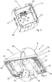
- FIG. 1 shows in a perspective view a signal device 100 according to the present invention.
- the signal device 100 has a sound signal unit 10, which is represented by a horn.
- the signal device 100 also has a light signal unit 11 which is attached to a housing base body 12 of the signal device 100.
- connection means 25 in the form of screws are provided, with which the light signal unit 11 is screwed onto a side wall 16 of the housing base body 12.
- the light signal unit 11 has a base body which is designed as a signal hood 15.
- the signal hood 15 serves as the element that emits the signal light, and a light source can be incorporated in the signal hood 15, through which the light signal is generated, but the signal hood 15 can also form the light source itself, for example if the signal hood 15 is designed as a surface emitter.
- the basic housing body 12 is closed by an upper housing part 13, and the audio signal unit 10 is arranged on the inside of the upper housing part 13.
- the upper housing part 13 can be connected to the basic housing body 12 by means of locking pins 26.
- the locking pins 26 can be designed in such a way that they are arranged in a self-retaining manner on the upper housing part 13, and if the upper housing part 13 is handled individually, a fitter need not also handle the locking pins 26 individually.
- the locking pins 26 can be locked in openings 27 which are made on the front side of the main housing body 12, see in this regard Figure 2 .
- the housing base body 12 has holes 28 which are made in fastening tabs 29 formed on the outside of the housing base body 12. Fastening means can be passed through the holes 28 in order to arrange the signal device 100 with the housing base body 12 on a receiving body.
- the depth of the basic housing body 12 is indicated by T G and the depth of the upper housing part 13 is indicated by T O , wherein the depth T O of the upper housing part 13 can be greater than shown in the illustration, because the upper housing part 13 can with part of its depth T. O protrude into the housing body 12.
- the housing of the signal device 100 has, for example, a cube shape without the light signal unit 11, the cube not having to have the same edge lengths.
- FIG. 2 shows the signal device 100 in an open form, in which the upper housing part 13 is removed.
- the receiving space 14 is shown in the housing base body 12, and the housing base body 12 is formed by a housing base 30 and four side walls 16 extending vertically on the sides of the rectangular housing base 30.
- hollow chambers 31 formed on the outside of the side walls 16 are provided, in which the openings 27 for locking the locking pins 26 are made on the front side.
- the side wall 16 arranged at the top has an opening 19, and the light signal unit 11 with the signal hood 15 is arranged on the upper side wall 16.
- An electrical switching unit is located approximately in the base of the pyramid-shaped signal hood 15 18 introduced, which partially protrudes through an opening 19 in the side wall 16 into the receiving space 14 of the housing base body 12.
- an electrical connection 22 with a line connection means 21 is shown, and electrical lines can be connected to the line connection means 21, which lines are passed through at least one housing wall 16 through corresponding housing openings 32.
- the perspective view shows the signal hood 15 with a connection frame 17 with which the signal hood 15 is placed on the outside of the side wall 16 of the housing base body 12.
- the connection frame 17 forms a rectangular base area of the pyramid-shaped signal hood 15, and the electrical switching unit 18 is formed by a carrier board which extends approximately in the plane of the connection frame 17.
- FIG. 4 shows a perspective view of the housing base body 12 with the line connection means 21, which is arranged on the housing base 30.
- a side wall 16 of the housing base body 12 has the opening 19, which has an approximately rectangular shape.
- the electrical connection 22 which is provided between the line connection means 21 and the light signal unit 11, which light signal unit 11 is shown in the following Figure 4 is shown in more detail.
- Figure 4 shows a perspective view of the light signal unit 11.
- the base body of the light signal unit 11 is formed by a signal hood 15 which has a pyramid shape.
- the base of the pyramid is spanned by a connection frame 17, the signal hood 15 being made of a light-transparent material.
- An electrical switching unit 18 is inserted in the rectangular connection frame 17 of the signal hood 15 and is connected to the signal hood 15 by connecting means 24.
- the signal hood 15 can first be provided, in which the electrical switching unit 18 is arranged on the bottom and is screwed with connecting means 24, for example in the form of screws.
- the light signal unit 11 can then be placed on the outside of the side wall 16 of the housing base body 12, and connecting means 25 (see FIG Figure 1 ) can be passed through connecting means receptacles 33 in order to subsequently connect the signal hood 15 to the base body 12.
- the light-emitting area of the signal hood 15 is indicated by A H
- the area of the base area is indicated by A G.
Landscapes
- Physics & Mathematics (AREA)
- General Physics & Mathematics (AREA)
- Arrangement Of Elements, Cooling, Sealing, Or The Like Of Lighting Devices (AREA)
- Non-Portable Lighting Devices Or Systems Thereof (AREA)
- Optical Communication System (AREA)
Priority Applications (1)
| Application Number | Priority Date | Filing Date | Title |
|---|---|---|---|
| PL12193868T PL2597630T3 (pl) | 2011-11-22 | 2012-11-22 | Urządzenie sygnalizacyjne z jednostką sygnału dźwiękowego i z jednostką sygnału świetlnego |
Applications Claiming Priority (1)
| Application Number | Priority Date | Filing Date | Title |
|---|---|---|---|
| DE201110055593 DE102011055593A1 (de) | 2011-11-22 | 2011-11-22 | Signalgerät mit einer Tonsignaleinheit und mit einer Lichtsignaleinheit |
Publications (3)
| Publication Number | Publication Date |
|---|---|
| EP2597630A2 EP2597630A2 (de) | 2013-05-29 |
| EP2597630A3 EP2597630A3 (de) | 2016-12-21 |
| EP2597630B1 true EP2597630B1 (de) | 2021-04-14 |
Family
ID=47290681
Family Applications (1)
| Application Number | Title | Priority Date | Filing Date |
|---|---|---|---|
| EP12193868.2A Active EP2597630B1 (de) | 2011-11-22 | 2012-11-22 | Signalgerät mit einer Tonsignaleinheit und mit einer Lichtsignaleinheit |
Country Status (6)
| Country | Link |
|---|---|
| US (1) | US9019116B2 (pl) |
| EP (1) | EP2597630B1 (pl) |
| CN (1) | CN103138778B (pl) |
| BR (1) | BR102012029694B1 (pl) |
| DE (1) | DE102011055593A1 (pl) |
| PL (1) | PL2597630T3 (pl) |
Family Cites Families (13)
| Publication number | Priority date | Publication date | Assignee | Title |
|---|---|---|---|---|
| US4904982A (en) * | 1988-02-18 | 1990-02-27 | Outboard Marine Corporation | Visual and audible warning device |
| US5132659A (en) * | 1990-07-03 | 1992-07-21 | Kuo Ching L | Flashing light siren alarm |
| US5825280A (en) * | 1995-09-15 | 1998-10-20 | Merendini; Andrew Vito | Portable safety light and audible signal apparatus |
| GB2319105A (en) * | 1996-11-07 | 1998-05-13 | Signature Ind Ltd | An alarm device |
| US7135960B2 (en) * | 2004-08-17 | 2006-11-14 | Ge Security, Inc. | Method and apparatus for indicating a status |
| US7375617B2 (en) * | 2005-02-22 | 2008-05-20 | Gentex Corporation | Evacuation appliance |
| CN100541548C (zh) | 2005-02-22 | 2009-09-16 | 金泰克斯公司 | 撤离用具 |
| US7602308B2 (en) * | 2006-09-27 | 2009-10-13 | Honeywell International Inc. | Plug-in alarm notification device |
| US7450026B2 (en) * | 2006-10-05 | 2008-11-11 | Cooper Technologies Company | Mounting plate for a notification appliance |
| CN201191432Y (zh) * | 2008-03-28 | 2009-02-04 | 华荣集团有限公司 | 防爆灯的声光报警器 |
| CN201288587Y (zh) * | 2008-09-18 | 2009-08-12 | 薛国顺 | 便携式矿山声光警戒报警器 |
| US7920069B2 (en) * | 2008-11-20 | 2011-04-05 | Floyd Bell Inc. | Audible, piezoelectric signal with integral visual signal |
| CN201936404U (zh) * | 2010-12-16 | 2011-08-17 | 西安特菲尔电子有限公司 | 分体式声光报警器 |
-
2011
- 2011-11-22 DE DE201110055593 patent/DE102011055593A1/de not_active Withdrawn
-
2012
- 2012-11-21 US US13/682,968 patent/US9019116B2/en active Active
- 2012-11-22 CN CN201210480460.XA patent/CN103138778B/zh active Active
- 2012-11-22 BR BR102012029694-2A patent/BR102012029694B1/pt active IP Right Grant
- 2012-11-22 PL PL12193868T patent/PL2597630T3/pl unknown
- 2012-11-22 EP EP12193868.2A patent/EP2597630B1/de active Active
Non-Patent Citations (1)
| Title |
|---|
| None * |
Also Published As
| Publication number | Publication date |
|---|---|
| BR102012029694A2 (pt) | 2016-11-01 |
| PL2597630T3 (pl) | 2021-07-26 |
| DE102011055593A1 (de) | 2013-05-23 |
| EP2597630A2 (de) | 2013-05-29 |
| BR102012029694B1 (pt) | 2021-05-25 |
| US9019116B2 (en) | 2015-04-28 |
| CN103138778B (zh) | 2015-12-09 |
| US20130127630A1 (en) | 2013-05-23 |
| EP2597630A3 (de) | 2016-12-21 |
| CN103138778A (zh) | 2013-06-05 |
Similar Documents
| Publication | Publication Date | Title |
|---|---|---|
| DE102013226855B4 (de) | Elektronische Steuerungsvorrichtung für ein Fahrzeug, und ein Verfahren zu deren Herstellung | |
| DE112013000684T5 (de) | Verbindereinheit | |
| DE102012023190A1 (de) | Signalsäule | |
| EP1347233A2 (de) | Signalsäule | |
| WO2015109351A1 (de) | Vorrichtung zum kontaktieren von elektrischen leitern, sowie leuchtsystem | |
| DE202014100951U1 (de) | Leuchte mit Trägerelement und lösbar befestigbarem Leuchtmodul | |
| DE102008035660A1 (de) | LED-Packungsanordnung | |
| DE112012002345T5 (de) | Montagestruktur einer Beleuchtungseinheit | |
| DE102012102842B4 (de) | Befestigung und Abdichtung von Steckanschlussmodulen in einer Gehäusewand | |
| WO2012150124A1 (de) | Leuchtvorrichtung | |
| DE202005017012U1 (de) | Elektrische Anschlusseinrichtung für eine Leiterplatte | |
| EP3231043B1 (de) | Wanddurchführung für steckverbinder | |
| DE102019112687A1 (de) | Wannenförmiges Leuchtengehäuse | |
| EP2597630A2 (de) | Signalgerät mit einer Tonsignaleinheit und mit einer Lichtsignaleinheit | |
| EP2597629B1 (de) | Signalgerät zur Aussendung eines akustischen und/oder visuellen Signals | |
| DE102015106578A1 (de) | Modulares Elektronikgehäuse | |
| EP1146278A2 (de) | Leuchtmittel, insbesondere für eine Signalleuchte | |
| EP2852725B1 (de) | Betätigungselement für ein kraftfahrzeug | |
| DE10038561A1 (de) | Leuchtmittel, insbesondere für eine Signalleuchte | |
| DE10353139B4 (de) | Stapelbares modulares Gehäusesystem und ein Verfahren zu dessen Herstellung | |
| DE102022124494A1 (de) | Geräteanschlusssteckverbinder mit Leuchtanzeige | |
| DE102018115823B3 (de) | Elektroinstallationsgehäuse mit Ausschlagmembran | |
| DE29811602U1 (de) | Leuchtelement in beliebiger geometrischer Form | |
| DE102012021238A1 (de) | Dichter Steckverbinder und LED-Leuchtmodul ausgestattet mit einem gedichteten Steckverbinder | |
| DE102014012686A1 (de) | Beleuchtungsanzeigesystem |
Legal Events
| Date | Code | Title | Description |
|---|---|---|---|
| PUAI | Public reference made under article 153(3) epc to a published international application that has entered the european phase |
Free format text: ORIGINAL CODE: 0009012 |
|
| AK | Designated contracting states |
Kind code of ref document: A2 Designated state(s): AL AT BE BG CH CY CZ DE DK EE ES FI FR GB GR HR HU IE IS IT LI LT LU LV MC MK MT NL NO PL PT RO RS SE SI SK SM TR |
|
| AX | Request for extension of the european patent |
Extension state: BA ME |
|
| PUAL | Search report despatched |
Free format text: ORIGINAL CODE: 0009013 |
|
| AK | Designated contracting states |
Kind code of ref document: A3 Designated state(s): AL AT BE BG CH CY CZ DE DK EE ES FI FR GB GR HR HU IE IS IT LI LT LU LV MC MK MT NL NO PL PT RO RS SE SI SK SM TR |
|
| AX | Request for extension of the european patent |
Extension state: BA ME |
|
| RIC1 | Information provided on ipc code assigned before grant |
Ipc: G08B 7/06 20060101AFI20161116BHEP |
|
| STAA | Information on the status of an ep patent application or granted ep patent |
Free format text: STATUS: REQUEST FOR EXAMINATION WAS MADE |
|
| 17P | Request for examination filed |
Effective date: 20170620 |
|
| RBV | Designated contracting states (corrected) |
Designated state(s): AL AT BE BG CH CY CZ DE DK EE ES FI FR GB GR HR HU IE IS IT LI LT LU LV MC MK MT NL NO PL PT RO RS SE SI SK SM TR |
|
| STAA | Information on the status of an ep patent application or granted ep patent |
Free format text: STATUS: EXAMINATION IS IN PROGRESS |
|
| 17Q | First examination report despatched |
Effective date: 20180612 |
|
| GRAP | Despatch of communication of intention to grant a patent |
Free format text: ORIGINAL CODE: EPIDOSNIGR1 |
|
| STAA | Information on the status of an ep patent application or granted ep patent |
Free format text: STATUS: GRANT OF PATENT IS INTENDED |
|
| INTG | Intention to grant announced |
Effective date: 20201116 |
|
| GRAS | Grant fee paid |
Free format text: ORIGINAL CODE: EPIDOSNIGR3 |
|
| GRAA | (expected) grant |
Free format text: ORIGINAL CODE: 0009210 |
|
| STAA | Information on the status of an ep patent application or granted ep patent |
Free format text: STATUS: THE PATENT HAS BEEN GRANTED |
|
| AK | Designated contracting states |
Kind code of ref document: B1 Designated state(s): AL AT BE BG CH CY CZ DE DK EE ES FI FR GB GR HR HU IE IS IT LI LT LU LV MC MK MT NL NO PL PT RO RS SE SI SK SM TR |
|
| REG | Reference to a national code |
Ref country code: GB Ref legal event code: FG4D Free format text: NOT ENGLISH |
|
| REG | Reference to a national code |
Ref country code: CH Ref legal event code: EP |
|
| REG | Reference to a national code |
Ref country code: DE Ref legal event code: R096 Ref document number: 502012016722 Country of ref document: DE |
|
| REG | Reference to a national code |
Ref country code: IE Ref legal event code: FG4D Free format text: LANGUAGE OF EP DOCUMENT: GERMAN |
|
| REG | Reference to a national code |
Ref country code: AT Ref legal event code: REF Ref document number: 1383122 Country of ref document: AT Kind code of ref document: T Effective date: 20210515 |
|
| REG | Reference to a national code |
Ref country code: LT Ref legal event code: MG9D |
|
| REG | Reference to a national code |
Ref country code: NL Ref legal event code: MP Effective date: 20210414 |
|
| PG25 | Lapsed in a contracting state [announced via postgrant information from national office to epo] |
Ref country code: BG Free format text: LAPSE BECAUSE OF FAILURE TO SUBMIT A TRANSLATION OF THE DESCRIPTION OR TO PAY THE FEE WITHIN THE PRESCRIBED TIME-LIMIT Effective date: 20210714 Ref country code: HR Free format text: LAPSE BECAUSE OF FAILURE TO SUBMIT A TRANSLATION OF THE DESCRIPTION OR TO PAY THE FEE WITHIN THE PRESCRIBED TIME-LIMIT Effective date: 20210414 Ref country code: LT Free format text: LAPSE BECAUSE OF FAILURE TO SUBMIT A TRANSLATION OF THE DESCRIPTION OR TO PAY THE FEE WITHIN THE PRESCRIBED TIME-LIMIT Effective date: 20210414 Ref country code: NL Free format text: LAPSE BECAUSE OF FAILURE TO SUBMIT A TRANSLATION OF THE DESCRIPTION OR TO PAY THE FEE WITHIN THE PRESCRIBED TIME-LIMIT Effective date: 20210414 Ref country code: FI Free format text: LAPSE BECAUSE OF FAILURE TO SUBMIT A TRANSLATION OF THE DESCRIPTION OR TO PAY THE FEE WITHIN THE PRESCRIBED TIME-LIMIT Effective date: 20210414 |
|
| PG25 | Lapsed in a contracting state [announced via postgrant information from national office to epo] |
Ref country code: LV Free format text: LAPSE BECAUSE OF FAILURE TO SUBMIT A TRANSLATION OF THE DESCRIPTION OR TO PAY THE FEE WITHIN THE PRESCRIBED TIME-LIMIT Effective date: 20210414 Ref country code: GR Free format text: LAPSE BECAUSE OF FAILURE TO SUBMIT A TRANSLATION OF THE DESCRIPTION OR TO PAY THE FEE WITHIN THE PRESCRIBED TIME-LIMIT Effective date: 20210715 Ref country code: IS Free format text: LAPSE BECAUSE OF FAILURE TO SUBMIT A TRANSLATION OF THE DESCRIPTION OR TO PAY THE FEE WITHIN THE PRESCRIBED TIME-LIMIT Effective date: 20210814 Ref country code: SE Free format text: LAPSE BECAUSE OF FAILURE TO SUBMIT A TRANSLATION OF THE DESCRIPTION OR TO PAY THE FEE WITHIN THE PRESCRIBED TIME-LIMIT Effective date: 20210414 Ref country code: RS Free format text: LAPSE BECAUSE OF FAILURE TO SUBMIT A TRANSLATION OF THE DESCRIPTION OR TO PAY THE FEE WITHIN THE PRESCRIBED TIME-LIMIT Effective date: 20210414 Ref country code: NO Free format text: LAPSE BECAUSE OF FAILURE TO SUBMIT A TRANSLATION OF THE DESCRIPTION OR TO PAY THE FEE WITHIN THE PRESCRIBED TIME-LIMIT Effective date: 20210714 Ref country code: PT Free format text: LAPSE BECAUSE OF FAILURE TO SUBMIT A TRANSLATION OF THE DESCRIPTION OR TO PAY THE FEE WITHIN THE PRESCRIBED TIME-LIMIT Effective date: 20210816 Ref country code: ES Free format text: LAPSE BECAUSE OF FAILURE TO SUBMIT A TRANSLATION OF THE DESCRIPTION OR TO PAY THE FEE WITHIN THE PRESCRIBED TIME-LIMIT Effective date: 20210414 |
|
| REG | Reference to a national code |
Ref country code: DE Ref legal event code: R097 Ref document number: 502012016722 Country of ref document: DE |
|
| PG25 | Lapsed in a contracting state [announced via postgrant information from national office to epo] |
Ref country code: RO Free format text: LAPSE BECAUSE OF FAILURE TO SUBMIT A TRANSLATION OF THE DESCRIPTION OR TO PAY THE FEE WITHIN THE PRESCRIBED TIME-LIMIT Effective date: 20210414 Ref country code: DK Free format text: LAPSE BECAUSE OF FAILURE TO SUBMIT A TRANSLATION OF THE DESCRIPTION OR TO PAY THE FEE WITHIN THE PRESCRIBED TIME-LIMIT Effective date: 20210414 Ref country code: EE Free format text: LAPSE BECAUSE OF FAILURE TO SUBMIT A TRANSLATION OF THE DESCRIPTION OR TO PAY THE FEE WITHIN THE PRESCRIBED TIME-LIMIT Effective date: 20210414 Ref country code: CZ Free format text: LAPSE BECAUSE OF FAILURE TO SUBMIT A TRANSLATION OF THE DESCRIPTION OR TO PAY THE FEE WITHIN THE PRESCRIBED TIME-LIMIT Effective date: 20210414 Ref country code: SM Free format text: LAPSE BECAUSE OF FAILURE TO SUBMIT A TRANSLATION OF THE DESCRIPTION OR TO PAY THE FEE WITHIN THE PRESCRIBED TIME-LIMIT Effective date: 20210414 Ref country code: SK Free format text: LAPSE BECAUSE OF FAILURE TO SUBMIT A TRANSLATION OF THE DESCRIPTION OR TO PAY THE FEE WITHIN THE PRESCRIBED TIME-LIMIT Effective date: 20210414 |
|
| PLBE | No opposition filed within time limit |
Free format text: ORIGINAL CODE: 0009261 |
|
| STAA | Information on the status of an ep patent application or granted ep patent |
Free format text: STATUS: NO OPPOSITION FILED WITHIN TIME LIMIT |
|
| 26N | No opposition filed |
Effective date: 20220117 |
|
| PG25 | Lapsed in a contracting state [announced via postgrant information from national office to epo] |
Ref country code: IS Free format text: LAPSE BECAUSE OF FAILURE TO SUBMIT A TRANSLATION OF THE DESCRIPTION OR TO PAY THE FEE WITHIN THE PRESCRIBED TIME-LIMIT Effective date: 20210814 Ref country code: AL Free format text: LAPSE BECAUSE OF FAILURE TO SUBMIT A TRANSLATION OF THE DESCRIPTION OR TO PAY THE FEE WITHIN THE PRESCRIBED TIME-LIMIT Effective date: 20210414 |
|
| PG25 | Lapsed in a contracting state [announced via postgrant information from national office to epo] |
Ref country code: MC Free format text: LAPSE BECAUSE OF FAILURE TO SUBMIT A TRANSLATION OF THE DESCRIPTION OR TO PAY THE FEE WITHIN THE PRESCRIBED TIME-LIMIT Effective date: 20210414 |
|
| REG | Reference to a national code |
Ref country code: CH Ref legal event code: PL |
|
| PG25 | Lapsed in a contracting state [announced via postgrant information from national office to epo] |
Ref country code: LU Free format text: LAPSE BECAUSE OF NON-PAYMENT OF DUE FEES Effective date: 20211122 Ref country code: BE Free format text: LAPSE BECAUSE OF NON-PAYMENT OF DUE FEES Effective date: 20211130 |
|
| REG | Reference to a national code |
Ref country code: BE Ref legal event code: MM Effective date: 20211130 |
|
| PG25 | Lapsed in a contracting state [announced via postgrant information from national office to epo] |
Ref country code: LI Free format text: LAPSE BECAUSE OF NON-PAYMENT OF DUE FEES Effective date: 20211130 Ref country code: CH Free format text: LAPSE BECAUSE OF NON-PAYMENT OF DUE FEES Effective date: 20211130 |
|
| PG25 | Lapsed in a contracting state [announced via postgrant information from national office to epo] |
Ref country code: IE Free format text: LAPSE BECAUSE OF NON-PAYMENT OF DUE FEES Effective date: 20211122 |
|
| PG25 | Lapsed in a contracting state [announced via postgrant information from national office to epo] |
Ref country code: HU Free format text: LAPSE BECAUSE OF FAILURE TO SUBMIT A TRANSLATION OF THE DESCRIPTION OR TO PAY THE FEE WITHIN THE PRESCRIBED TIME-LIMIT; INVALID AB INITIO Effective date: 20121122 Ref country code: CY Free format text: LAPSE BECAUSE OF FAILURE TO SUBMIT A TRANSLATION OF THE DESCRIPTION OR TO PAY THE FEE WITHIN THE PRESCRIBED TIME-LIMIT Effective date: 20210414 |
|
| P01 | Opt-out of the competence of the unified patent court (upc) registered |
Effective date: 20230530 |
|
| PG25 | Lapsed in a contracting state [announced via postgrant information from national office to epo] |
Ref country code: MK Free format text: LAPSE BECAUSE OF FAILURE TO SUBMIT A TRANSLATION OF THE DESCRIPTION OR TO PAY THE FEE WITHIN THE PRESCRIBED TIME-LIMIT Effective date: 20210414 |
|
| PG25 | Lapsed in a contracting state [announced via postgrant information from national office to epo] |
Ref country code: TR Free format text: LAPSE BECAUSE OF FAILURE TO SUBMIT A TRANSLATION OF THE DESCRIPTION OR TO PAY THE FEE WITHIN THE PRESCRIBED TIME-LIMIT Effective date: 20210414 |
|
| PG25 | Lapsed in a contracting state [announced via postgrant information from national office to epo] |
Ref country code: MT Free format text: LAPSE BECAUSE OF FAILURE TO SUBMIT A TRANSLATION OF THE DESCRIPTION OR TO PAY THE FEE WITHIN THE PRESCRIBED TIME-LIMIT Effective date: 20210414 |
|
| PGFP | Annual fee paid to national office [announced via postgrant information from national office to epo] |
Ref country code: DE Payment date: 20251031 Year of fee payment: 14 |
|
| PGFP | Annual fee paid to national office [announced via postgrant information from national office to epo] |
Ref country code: GB Payment date: 20251120 Year of fee payment: 14 |
|
| PGFP | Annual fee paid to national office [announced via postgrant information from national office to epo] |
Ref country code: AT Payment date: 20251117 Year of fee payment: 14 |
|
| PGFP | Annual fee paid to national office [announced via postgrant information from national office to epo] |
Ref country code: IT Payment date: 20251128 Year of fee payment: 14 |
|
| PGFP | Annual fee paid to national office [announced via postgrant information from national office to epo] |
Ref country code: FR Payment date: 20251120 Year of fee payment: 14 |
|
| PGFP | Annual fee paid to national office [announced via postgrant information from national office to epo] |
Ref country code: PL Payment date: 20251110 Year of fee payment: 14 |