EP2597213B1 - Sanitäres Einbauteil - Google Patents
Sanitäres Einbauteil Download PDFInfo
- Publication number
- EP2597213B1 EP2597213B1 EP20110009381 EP11009381A EP2597213B1 EP 2597213 B1 EP2597213 B1 EP 2597213B1 EP 20110009381 EP20110009381 EP 20110009381 EP 11009381 A EP11009381 A EP 11009381A EP 2597213 B1 EP2597213 B1 EP 2597213B1
- Authority
- EP
- European Patent Office
- Prior art keywords
- housing
- installation
- installation part
- outflow
- face
- Prior art date
- Legal status (The legal status is an assumption and is not a legal conclusion. Google has not performed a legal analysis and makes no representation as to the accuracy of the status listed.)
- Active
Links
Images



Classifications
-
- E—FIXED CONSTRUCTIONS
- E03—WATER SUPPLY; SEWERAGE
- E03C—DOMESTIC PLUMBING INSTALLATIONS FOR FRESH WATER OR WASTE WATER; SINKS
- E03C1/00—Domestic plumbing installations for fresh water or waste water; Sinks
- E03C1/02—Plumbing installations for fresh water
- E03C1/08—Jet regulators or jet guides, e.g. anti-splash devices
- E03C1/084—Jet regulators with aerating means
Definitions
- the invention relates to a sanitary fitting to which has a vented jet regulator or configured as such and has a mounting housing, which mounting housing has a thread for attachment to a provided at the water outlet of a sanitary outlet fitting mating thread and inserted into the at least one insert part up to an insertion stop wherein the mounting housing has a downstream housing end face with flow holes and wherein the peripheral wall of the mounting housing at least in an at least double-walled designed portion bounds at least one ventilation channel, which is open to the downstream housing end open and opens into at least one, leading into the housing interior of the mounting housing ventilation opening .
- Sanitary components are required as jet former, non-aerated jet regulator, jet aerator, flow regulator or non-return valve in various designs.
- aerated jet regulators so-called jet aerators, have been created to form a homogeneous, non-spattering and pearly-soft jet of water.
- a sanitary fitting of the type mentioned is known, which is designed as a ventilated jet regulator.
- the previously known jet regulator has a sleeve-shaped installation housing, which has an internal thread on its inflow-side sleeve inner circumference, which is intended to be fastened to a counter-thread provided on the water outlet of a sanitary outlet fitting.
- a sleeve-shaped installation housing In the sleeve interior of the sleeve-shaped installation housing at least one insert part can be used up to an insertion stop.
- the at least one insert part is designed as a jet splitter, which has to divide the incoming water flow into a plurality of individual jets, which are then enriched in the sleeve interior with ambient air and vented before the thus aerated water emerges as a homogeneous water jet through flow holes, which at a downstream housing end face the jet regulator housing are provided.
- the peripheral wall of the installation housing in a double-walled configured partial area surrounds a ventilation channel which is open towards the downstream housing end and opens into at least one ventilation opening leading into the housing interior of the installation housing.
- a comparable aerated jet regulator which has, however, at its jet regulator housing a specified for attachment to the water outlet of the outlet fitting external thread, is from the US 3827636 previously known.
- the disclosure of this document corresponds to the preamble of claim 1.
- the outer peripheral side carries at its jet regulator housing, for example, an external thread which is releasably connectable with an internal thread on the water outlet of the outlet fitting.
- a handle for manual detection of the jet regulator is provided on Aüslaufstirnend Scheme of the prior art jet regulator, which can be designed as a bracket, forming the bracket ends mounted on the jet regulator housing pivot axis.
- pivotally mounted on the jet body handle requires a considerable effort.
- the previously known regulating device has a sleeve-shaped installation housing with an internal thread on the inlet-side sleeve inner circumference, which internal thread can be mounted on an external thread on the water outlet of the sanitary outlet fitting.
- the provided between the prior art fitting and the water outlet of the sanitary outlet fitting screw can be actuated, in which the mounting housing is detected on the outer peripheral side.
- a throttle or regulating element is held helically adjustable in the axial direction.
- a hexagon socket is on its downstream end face provided, which serves as a tool engagement surface for a turning tool.
- the jet regulator housing of the previously known jet regulator has a downstream housing part region, which has a housing outer circumference which is reduced in relation to the inflow-side housing partial region.
- the downstream housing part region can be used in an insertion opening of a rotary tool such that the rotary tool can be attached to a tool engagement surface in a rotationally fixed manner, which is provided approximately at the downstream end edge of the downstream housing part region.
- a jet aerator which has in its installation housing serving as a beam splitter perforated plate having a number of flow holes for generating a plurality of individual jets. Pins are provided in the outflow region of the throughflow holes, whose free and conically tapering pin end pointing towards the perforated plate is designed as a deflection slope which deflects each of the individual beams coming from the throughflow holes obliquely to the flow direction.
- a sleeve-shaped outlet nozzle is provided, in which the installation housing can be used up to an insertion stop. At the outlet mouthpiece a thread is provided that can be screwed to a corresponding mating thread on the water outlet.
- the external appearance of the outlet fitting is determined by the water outlet and the adjacent outlet nozzle and its screw connection at the water outlet. In order to create an aesthetically pleasing appearance, it is necessary to make the visible surfaces of the outlet mouthpiece on the one hand and the outlet fitting in the region of its water outlet on the other hand as uniform as possible. Nevertheless, there remains a narrow gap between the outlet nozzle and the jet regulator insert, which tends to be soiled and can have a disturbing effect.
- a jet aerator serving as a sanitary fitting with a multipart installation housing that has an external thread on its outer circumference for screwing into a provided on the inner circumference of the water outlet of a sanitary outlet fitting internal thread (see. DE 10 2005 010 551 A1 ).
- a flow straightener On the installation housing downstream of a flow straightener is formed, which is designed as a, flow holes having perforated plate, which forms the downstream housing end face.
- a plurality of lattice-shaped inserts are used, which serve as Strahlregulier observed, which has to form the ventilated inside the housing individual rays back to a homogeneous, non-squirting overall jet.
- the downstream housing front edge has a profiling, which can serve as a tool engagement surface of the corresponding profiling of a further installation housing used as a turning tool. Since the out DE 10 2005 010 551 A1 previously known jet aerator can be screwed so deep into the water outlet of a sanitary outlet fitting that the downstream housing end face of the mounting housing does not project beyond the water outlet of the outlet fitting, the aesthetic impression is determined solely by the outlet fitting. To the installation housing at side of the installation housing does not project beyond the water outlet of the outlet fitting, the aesthetic impression is determined solely by the outlet fitting. In order to mount or dismount the installation housing at the water outlet of the outlet fitting, but always another installation housing or other special turning tool is required, which is not always available, especially in a household.
- From the US-A-4,534,513 is therefore also a jet regulator with a sleeve-shaped installation housing previously known, which carries at its downstream housing circumference an external thread with which the installation housing can be screwed to an inner peripheral side provided at the water outlet of the outlet fitting internal thread.
- the installation housing has a downstream housing end face, which is formed by superimposed layers of metal screens and which is guided displaceably in the housing interior of the installation housing.
- the displaceability of the housing end face has the consequence that the flow conditions in the housing interior of the previously known jet regulator may change, so that the previously known jet regulator may not have consistent and in particular no consistent and in particular no consistently good beam quality and requires a large amount of installation space.
- downstream housing front is convex or convex curved in the outflow direction and has at least one slot whose opposite slot longitudinal sides as turning or tool engagement surfaces for a in the at least a slot insertable rotary tool are configured, and that the inner housing wall protrudes beyond the outer housing wall and forms the downstream housing end edge.
- the built-in part according to the invention has a one- or multi-part installation housing, which has an external thread on its housing outer circumference, which is intended for screwing into a provided on the inner circumference of the water outlet of a sanitary outlet fitting internal thread.
- the fitting according to the invention can be screwed into the internal thread of the water outlet.
- the peripheral wall of the installation housing defines at least in an at least double-walled configured portion of at least one ventilation duct, which is open to the downstream housing end side and which opens into at least one, leading into the housing interior of the installation housing ventilation opening.
- at least one ventilation duct which is open to the downstream housing end side and which opens into at least one, leading into the housing interior of the installation housing ventilation opening.
- the downstream end face of the housing is convexly or convexly curved in the outflow direction and has at least one slot, the opposite slot longitudinal sides are designed as a turning or tool engagement surfaces for a releasably insertable in the at least one slot rotary tool.
- the fitting according to the invention thus has on its downstream housing end face at least one slot, the opposite slot longitudinal sides are designed as a rotary control surfaces or tool engagement surfaces for a, in the at least one slot releasably insertable rotary tool.
- the downstream housing front side is formed in the outflow such convex or convex curved that the slot can be made sufficiently deep to provide the rotary tool on the corresponding deep slot longitudinal sides a sufficient turning or tool engagement surface, without thereby excessively large space in the housing interior get lost.
- downstream end of the housing In order to be able to form the water jet emerging from the built-in part well, without the downstream end of the housing offering a high flow resistance, it is expedient for the downstream end of the housing to be designed as a grid, mesh or hole structure.
- the at least one slot can be designed as a slot-shaped opening of the housing end face.
- a preferred embodiment according to the invention provides that the at least one slot has a slot or groove bottom, which is closed or - for example, by a slot or groove bottom forming hole or grid structure - open or liquid-permeable designed.
- the housing end face has a cross-sectional thickening at least in the region of the at least one slot.
- slot longitudinal sides have a greater wall thickness in comparison with the flow guide walls forming the grid, mesh or hole structure of the housing end face.
- the installation housing has a downstream housing section with a housing cross-section reduced relative to an adjacent inflow-side housing section, and if a free end edge of the housing section projecting above the water outlet serves as a drip edge.
- a designed according to this invention proposal sanitary fitting has a downstream housing portion which has a relation to the adjacent inflow-side housing portion reduced housing cross-section.
- the free end edge of the over the water outlet projecting outflow side housing section is ausgestaltext as dripping edge on which the remaining water can still drain after closing the stopcock without overflowing on the outside of the outlet fitting and run along there.
- the mounting housing has at least in a downstream housing portion an outer, at least a portion of the outer thread bearing housing wall and a spaced by the at least one ventilation duct inner housing wall.
- the inner housing wall can also be configured as a drip edge when the inner housing wall projects beyond the outer housing wall and forms the downstream housing front edge.
- the inner and the outer housing are preferably connected to each other via radial webs and if at least two webs as turning or tool engagement surfaces are provided for an insertable into the space between the webs rotary tool.
- the water flowing through pressure can be regulated independently of pressure to a maximum water volume per unit time, it is advantageous if the mounting part has a flow rate regulator, which is connected upstream of the aerated jet regulator in the flow direction.
- the preferably aerated jet regulator and optionally the flow rate regulator Front screen is upstream in the flow direction.
- annular seal made of preferably soft elastic material is provided for axial sealing between the mounting part and an annular outlet located in the water outlet.
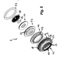
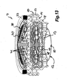
- FIGS. 1 to 13 is a sanitary fitting in various versions 5, 6 and 7 shown.
- the built-in parts 5, 6 and 7 shown here can be mounted on the water outlet 70 of a sanitary outlet fitting 8 not otherwise shown here.
- the built-in parts 5, 6 and 7 have a mounting housing 9, which has an external thread 10 on its outer circumference.
- the external thread 10 is intended for screwing into an internal thread 11, which is provided on the inner circumference of the water outlet 70 of the sanitary outlet fitting 8.
- the installation housing 9 has a downstream housing end 12 with flow holes 13.
- This ventilation duct 14 which is open to the downstream, in the figures lower housing end side 12, opens into a plurality of ventilation openings 15, which are arranged distributed uniformly over the housing circumference and lead into the housing interior of the installation housing 9.
- the ventilation channel 14 and the ventilation openings 15 are part of a built-in parts 5 and 6 beam regulator 16, a so-called Strahlbelpresenters.
- the installation element 7 itself is designed as a jet regulator.
- the installation housing 9 of the built-in parts 5, 6 and 7 has in its downstream housing section an outer housing wall 17 and a spaced apart by the ventilation channel 14 inner housing wall 18, of which the inner housing wall 18 projects beyond the outer housing 17 and the downstream housing end edge forms.
- the outer housing wall 17 carries at least a portion of the external thread 10.
- the inner and outer housing 17, 18 are connected to each other via radial webs 19, wherein the webs 19 provided as a turning or tool engagement surface for an insertable into the space between the webs 19 rotary tool are.
- the downstream housing end face 12 of the built-in parts 5, 6 and 7 shown in FIGS. 1 to 13 has at least one slot 20, 21 whose opposite slot longitudinal sides act as Turning or tool engagement surfaces are designed for a rotary tool, which is releasably insertable into the at least one slot 20 and 21 respectively.
- a turning tool a screwdriver, but preferably also serve a coin. So that with the help of the insertable into the slot 20, 21 rotary tool and a higher torque can be transmitted, the downstream housing end 12 in the outflow convex or convex, so that the slot longitudinal sides are preferably designed deep without the housing end face 12 in the Housing interior space would significantly limit available space.
- At least one insert part can be used up to an insertion stop. So will the FIGS. 1 to 12 clearly that in the installation housing 9 of the built-in parts 5, 6 and 7, a trained as a beam splitter insert part can be used, which has to divide the water flow into a plurality of individual jets and to a plurality of flow openings 22 has.
- the serving as a beam splitter insert part is here as a diffuser 23 forms, which has a flow opening 22 bearing ring wall 24.
- a central baffle 25 is formed, which deflects the inflowing water flow in the direction of the peripheral flow openings 22.
- the diffuser 23 is encompassed by a diffuser ring 26 such that between the inner circumference of the diffuser ring 26 and the outer circumference of the diffuser 23, a flow channel 30 tapering in the direction of flow is provided.
- the ventilation openings 15 are covered by the diffuser ring 26 at a distance such that the adjacent portion of the diffuser ring 26 serves as a splash guard 27 for the ventilation openings 15 against the water flowing on the inner circumference of the diffuser ring 26.
- the diffuser ring 26 of the built-in parts 2, 5 and 6 has air flow openings 29, which narrow in the flow direction to an air flow slot.
- the ambient air can thus be sucked through the ventilation channel 14 through the ventilation openings 15 in the peripheral wall and the Heil choir Anlagenen 29 in the diffuser ring 26 into the housing interior of the mounting housing 9 to mix there with the individual beams generated by the diffuser 23 before they again at the serving as a flow straightener housing front page 12 to be united and formed into a homogeneous, non-spraying and bead-soft aerated overall jet.
- the integrated into the built-in parts 5 and 6 jet regulator 16 thus consists essentially of the diffuser 23, the associated diffuser ring 26, and designed as a flow rectifier housing end face 12 of the mounting housing.
- a beam splitter which is designed as a perforated plate 40, which has a corresponding number of axial flow holes 41 for dividing the inflowing water into a plurality of individual jets.
- annular flow passage 30 tapering in the direction of flow is provided between the inner circumference of the diffuser ring 26 and the outer circumference of the diffuser 23.
- this tapered flow channel 30 the separated individual streams in the diffuser 23 are accelerated such that on the downstream side of the diffuser 23 in the region of the downstream channel opening of the flow channel 30, a negative pressure.
- the passage cross-section in the flow holes 41 of the perforated plate 40 is narrowed such that the individual beams generated by the perforated plate 40 are accelerated so that even on the downstream side of the perforated plate 40, a negative pressure.
- a sealing ring 33 is preferably made of soft elastic material, which seals the separating gaps between the housing 9 and the housing 26 and diffuser between diffuser 26 and diffuser 23 and the axial sealing between the inflow-side end edge of the mounting housing 9 and an annular shoulder in the water outlet 7 of the sanitary outlet fitting. 8 can be clamped.
- a flow rate controller 34 is connected upstream, which has an annular throttle body 35 made of elastic material, which throttle body 35 between itself and a Regelprofiltechnik 36 a changed under the pressure of the water flowing through the control gap 37.
- This flow rate regulator 34 is connected via a latching connection with the jet regulator 16 following in the flow direction and in particular with its diffuser 23.
- the flow rate regulator 34 is preceded by an attachment screen 38, which conically tapers counter to the flow direction, and has to filter out the dirt particles entrained in the water before these dirt particles can impair the function of the flow rate regulator 34 or the downstream jet regulator.
- a comparable attachment screen 38 is also provided in front of the installation part 7.
- the built-in part 5, 6 and 7 shown here can be screwed with its provided on the housing housing 9 external thread 10 in the internal thread 11 at the water outlet 7 a sanitary outlet fitting, otherwise for mounting required for a commercial jet regulator 3 outlet nozzle 28 is required. In this way it is possible to use the outlet fitting either in conjunction with an outlet nozzle 28 and a commercial jet regulator 3 used therein or in conjunction with one of the built-in parts 5, 6 and 7 according to the invention.
Landscapes
- Health & Medical Sciences (AREA)
- Life Sciences & Earth Sciences (AREA)
- Engineering & Computer Science (AREA)
- Hydrology & Water Resources (AREA)
- Public Health (AREA)
- Water Supply & Treatment (AREA)
- Nozzles (AREA)
- Domestic Plumbing Installations (AREA)
- Control Of Vending Devices And Auxiliary Devices For Vending Devices (AREA)
- Devices For Dispensing Beverages (AREA)
Priority Applications (11)
| Application Number | Priority Date | Filing Date | Title |
|---|---|---|---|
| PL14004341T PL2915927T3 (pl) | 2011-11-25 | 2011-11-25 | Regulator strumienia |
| PL13005956T PL2743410T3 (pl) | 2011-11-25 | 2011-11-25 | Wkładka sanitarna |
| EP13005956.1A EP2743410B1 (de) | 2011-11-25 | 2011-11-25 | Sanitäres Einbauteil |
| EP20110009381 EP2597213B1 (de) | 2011-11-25 | 2011-11-25 | Sanitäres Einbauteil |
| PL11009381T PL2597213T3 (pl) | 2011-11-25 | 2011-11-25 | Wkładka sanitarna |
| ES11009381.2T ES2540604T3 (es) | 2011-11-25 | 2011-11-25 | Componente de montaje sanitario |
| PT110093812T PT2597213E (pt) | 2011-11-25 | 2011-11-25 | Peça de instalação sanitária |
| EP14004341.5A EP2915927B1 (de) | 2011-11-25 | 2011-11-25 | Strahlregler |
| ES14004341T ES2793529T3 (es) | 2011-11-25 | 2011-11-25 | Regulador de chorro |
| EP19174316.0A EP3572593B1 (de) | 2011-11-25 | 2011-11-25 | Strahlregler |
| ES13005956T ES2748443T3 (es) | 2011-11-25 | 2011-11-25 | Componente de instalación sanitaria |
Applications Claiming Priority (1)
| Application Number | Priority Date | Filing Date | Title |
|---|---|---|---|
| EP20110009381 EP2597213B1 (de) | 2011-11-25 | 2011-11-25 | Sanitäres Einbauteil |
Related Child Applications (5)
| Application Number | Title | Priority Date | Filing Date |
|---|---|---|---|
| EP19174316.0A Division EP3572593B1 (de) | 2011-11-25 | 2011-11-25 | Strahlregler |
| EP13005956.1A Division EP2743410B1 (de) | 2011-11-25 | 2011-11-25 | Sanitäres Einbauteil |
| EP13005956.1A Division-Into EP2743410B1 (de) | 2011-11-25 | 2011-11-25 | Sanitäres Einbauteil |
| EP14004341.5A Division EP2915927B1 (de) | 2011-11-25 | 2011-11-25 | Strahlregler |
| EP14004341.5A Division-Into EP2915927B1 (de) | 2011-11-25 | 2011-11-25 | Strahlregler |
Publications (2)
| Publication Number | Publication Date |
|---|---|
| EP2597213A1 EP2597213A1 (de) | 2013-05-29 |
| EP2597213B1 true EP2597213B1 (de) | 2015-04-15 |
Family
ID=45098805
Family Applications (4)
| Application Number | Title | Priority Date | Filing Date |
|---|---|---|---|
| EP20110009381 Active EP2597213B1 (de) | 2011-11-25 | 2011-11-25 | Sanitäres Einbauteil |
| EP19174316.0A Active EP3572593B1 (de) | 2011-11-25 | 2011-11-25 | Strahlregler |
| EP14004341.5A Active EP2915927B1 (de) | 2011-11-25 | 2011-11-25 | Strahlregler |
| EP13005956.1A Active EP2743410B1 (de) | 2011-11-25 | 2011-11-25 | Sanitäres Einbauteil |
Family Applications After (3)
| Application Number | Title | Priority Date | Filing Date |
|---|---|---|---|
| EP19174316.0A Active EP3572593B1 (de) | 2011-11-25 | 2011-11-25 | Strahlregler |
| EP14004341.5A Active EP2915927B1 (de) | 2011-11-25 | 2011-11-25 | Strahlregler |
| EP13005956.1A Active EP2743410B1 (de) | 2011-11-25 | 2011-11-25 | Sanitäres Einbauteil |
Country Status (4)
| Country | Link |
|---|---|
| EP (4) | EP2597213B1 (pl) |
| ES (3) | ES2748443T3 (pl) |
| PL (3) | PL2597213T3 (pl) |
| PT (1) | PT2597213E (pl) |
Cited By (1)
| Publication number | Priority date | Publication date | Assignee | Title |
|---|---|---|---|---|
| DE202019000519U1 (de) | 2019-02-04 | 2020-05-12 | Gebr. Kemper Gmbh + Co. Kg | Freier Auslauf über einem Entwässerungsgegenstand |
Families Citing this family (6)
| Publication number | Priority date | Publication date | Assignee | Title |
|---|---|---|---|---|
| DE202015001886U1 (de) * | 2015-03-09 | 2016-06-10 | Neoperl Gmbh | Sanitäre Einsetzeinheit |
| DE102015005806A1 (de) * | 2015-05-05 | 2016-11-10 | Neoperl Gmbh | Strahlregler |
| DE202015003301U1 (de) | 2015-05-05 | 2016-08-09 | Neoperl Gmbh | Strahlregler |
| CN106948423B (zh) * | 2017-05-09 | 2022-12-09 | 李军 | 一种射束起泡器 |
| DE202017105379U1 (de) * | 2017-09-06 | 2018-12-07 | Neoperl Gmbh | Strahlregler |
| DE202019106347U1 (de) * | 2019-11-14 | 2021-02-16 | Neoperl Gmbh | Strahlregler |
Citations (1)
| Publication number | Priority date | Publication date | Assignee | Title |
|---|---|---|---|---|
| WO2006005099A2 (de) * | 2004-07-14 | 2006-01-19 | Siegfried Kogelbauer | Durchflussmengenbegrenzer |
Family Cites Families (27)
| Publication number | Priority date | Publication date | Assignee | Title |
|---|---|---|---|---|
| CH380042A (de) | 1960-05-13 | 1964-07-15 | Karrer Weber & Cie Ag | Wasserausflussarmatur |
| US3014667A (en) | 1961-06-21 | 1961-12-26 | Speakman Co | Aerator with flow control device |
| US3424387A (en) * | 1962-06-27 | 1969-01-28 | Elie P Aghnides | Water aerators |
| US3827636A (en) * | 1973-02-15 | 1974-08-06 | American Standard Inc | Substantially leakless aerator |
| US4534513A (en) | 1983-01-13 | 1985-08-13 | Aghnides Elie P | Concealed aerator |
| US4534514A (en) | 1983-01-13 | 1985-08-13 | Aghnides Elie P | Concealed aerator which seals against a spout when inserted therein |
| DE3440883A1 (de) * | 1984-11-09 | 1986-05-15 | Gottfried 6204 Taunusstein Ruhnke | Durchflussbegrenzer fuer fluessigkeiten |
| DE3442603A1 (de) * | 1984-11-22 | 1986-05-22 | Dieter 6229 Schlangenbad Kuhn | Durchflussbegrenzer fuer gasfoermige und fluessige medien |
| DE3534113A1 (de) * | 1985-09-25 | 1987-04-02 | Gottfried Ruhnke | Perlator fuer wasserhahnmundstuecke |
| DE9314990U1 (de) | 1993-10-02 | 1993-11-25 | Dieter Wildfang GmbH, 79379 Müllheim | Strahlregler zum Anschluß an Sanitärarmaturen |
| US6513731B2 (en) | 2001-01-02 | 2003-02-04 | Moen Incorporated | Aerator with variable air input |
| DE102005010551B4 (de) | 2005-03-04 | 2007-05-16 | Neoperl Gmbh | Sanitäre Funktionseinheit |
| DE202005001101U1 (de) * | 2005-01-25 | 2005-04-14 | Neoperl Gmbh | Filtersieb für Wasserauslaufarmaturen |
| DE102005003276B4 (de) * | 2005-01-25 | 2015-03-12 | Neoperl Gmbh | Sanitäre Funktionseinheit für eine Wasserauslaufarmatur |
| DE102005010550B4 (de) * | 2005-03-04 | 2007-03-22 | Neoperl Gmbh | Sanitärer Wasserauslauf |
| DE102005011194A1 (de) | 2005-03-09 | 2006-09-14 | Neoperl Gmbh | Sanitäre Auslaufarmatur |
| JP4542599B2 (ja) * | 2005-05-18 | 2010-09-15 | ネオパール ゲーエムベーハー | 水まわり部品、すなわち流れる流体媒体のための流れ調節器または流れ整形器、そのような水まわり部品の製造方法、ならびにそのような水まわり部品の使用 |
| DE202005021363U1 (de) * | 2005-05-18 | 2007-10-18 | Neoperl Gmbh | Sanitärkomponente, nämlich Strahlregler oder Strahlformer für strömende, fluide Medien |
| US7374366B2 (en) * | 2006-02-21 | 2008-05-20 | Chang-Hua Tasi | Wave generator |
| DE102007003296B3 (de) * | 2007-01-23 | 2008-07-10 | Neoperl Gmbh | Strahlbelüfter |
| DE202008010717U1 (de) * | 2008-08-12 | 2009-12-24 | Neoperl Gmbh | Sanitärer Wasserauslauf |
| DE202008010725U1 (de) * | 2008-08-12 | 2009-12-24 | Neoperl Gmbh | Strahlregler |
| DE102008050247A1 (de) * | 2008-09-01 | 2010-03-04 | Klaus Prenzler | Reguliereinrichtung für einen Wasserauslauf insbesondere von Sanitärarmaturen |
| DE102010007871B4 (de) * | 2010-02-13 | 2015-02-05 | Neoperl Gmbh | Strahlregler |
| DE202010014392U1 (de) * | 2010-09-28 | 2012-01-04 | Neoperl Gmbh | Sanitäre Funktionseinheit |
| DE102010064619B4 (de) * | 2010-09-28 | 2024-06-20 | Neoperl Gmbh | Sanitäres Einbauteil |
| DE202010014393U1 (de) * | 2010-09-28 | 2012-01-02 | Neoperl Gmbh | Sanitäres Einbauteil |
-
2011
- 2011-11-25 EP EP20110009381 patent/EP2597213B1/de active Active
- 2011-11-25 EP EP19174316.0A patent/EP3572593B1/de active Active
- 2011-11-25 PT PT110093812T patent/PT2597213E/pt unknown
- 2011-11-25 PL PL11009381T patent/PL2597213T3/pl unknown
- 2011-11-25 EP EP14004341.5A patent/EP2915927B1/de active Active
- 2011-11-25 EP EP13005956.1A patent/EP2743410B1/de active Active
- 2011-11-25 ES ES13005956T patent/ES2748443T3/es active Active
- 2011-11-25 PL PL13005956T patent/PL2743410T3/pl unknown
- 2011-11-25 PL PL14004341T patent/PL2915927T3/pl unknown
- 2011-11-25 ES ES14004341T patent/ES2793529T3/es active Active
- 2011-11-25 ES ES11009381.2T patent/ES2540604T3/es active Active
Patent Citations (1)
| Publication number | Priority date | Publication date | Assignee | Title |
|---|---|---|---|---|
| WO2006005099A2 (de) * | 2004-07-14 | 2006-01-19 | Siegfried Kogelbauer | Durchflussmengenbegrenzer |
Cited By (2)
| Publication number | Priority date | Publication date | Assignee | Title |
|---|---|---|---|---|
| DE202019000519U1 (de) | 2019-02-04 | 2020-05-12 | Gebr. Kemper Gmbh + Co. Kg | Freier Auslauf über einem Entwässerungsgegenstand |
| EP3690152A1 (de) | 2019-02-04 | 2020-08-05 | Gebr. Kemper GmbH + Co. KG Metallwerke | Freier auslauf über einem entwässerungsgegenstand |
Also Published As
| Publication number | Publication date |
|---|---|
| EP2743410B1 (de) | 2019-08-14 |
| EP2597213A1 (de) | 2013-05-29 |
| EP2915927A2 (de) | 2015-09-09 |
| EP2743410A3 (de) | 2014-09-03 |
| ES2793529T3 (es) | 2020-11-16 |
| EP2915927B1 (de) | 2020-04-15 |
| PL2597213T3 (pl) | 2015-08-31 |
| ES2540604T3 (es) | 2015-07-10 |
| PT2597213E (pt) | 2015-08-27 |
| PL2915927T3 (pl) | 2020-08-10 |
| ES2748443T3 (es) | 2020-03-16 |
| EP3572593A3 (de) | 2020-09-02 |
| EP3572593A2 (de) | 2019-11-27 |
| EP2915927A3 (de) | 2015-11-11 |
| EP3572593B1 (de) | 2026-03-04 |
| PL2743410T3 (pl) | 2020-01-31 |
| EP2743410A2 (de) | 2014-06-18 |
Similar Documents
| Publication | Publication Date | Title |
|---|---|---|
| DE102010064619B4 (de) | Sanitäres Einbauteil | |
| EP2089581B1 (de) | Strahlregler | |
| EP2597213B1 (de) | Sanitäres Einbauteil | |
| DE102010012326B4 (de) | Strahlregler | |
| EP2580398A1 (de) | Durchflussmengenregler | |
| WO2017076478A1 (de) | Strahlregler, der in eine reinigungsstellung verschwenkbar ist | |
| DE202010009023U1 (de) | Strahlregler | |
| EP2341195A2 (de) | Sanitäre Funktionseinheit mit Belüftungskanal zum Einsetzen in einen Armaturenauslauf | |
| DE102009021410A1 (de) | Strahlregler sowie sanitärer Wasserauslauf | |
| EP1789636A1 (de) | Sanitäre auslaufeinheit | |
| DE202010014392U1 (de) | Sanitäre Funktionseinheit | |
| DE102010048702A1 (de) | Sanitäre Funktionseinheit | |
| DE102010023665B4 (de) | Strahlregler | |
| DE102004008594B4 (de) | Sanitäre Auslaufvorrichtung | |
| DE102015014309B4 (de) | Strahlregler | |
| DE102008038727A1 (de) | Sanitärer Wasserauslauf | |
| EP2930277A1 (de) | Sanitäre funktionseinheit | |
| DE102006062986B3 (de) | Sanitäre Auslaufarmatur mit einem Strahlregler | |
| DE202010014393U1 (de) | Sanitäres Einbauteil | |
| DE102006062983B3 (de) | Strahlregler | |
| DE102006021801A1 (de) | Sanitäre Auslaufeinheit | |
| EP2129838B1 (de) | Strahlformer | |
| DE29601623U1 (de) | Durchflußmengenregler o.dgl. Drossel | |
| DE202004002745U1 (de) | Sanitäre Auslaufvorrichtung | |
| DE202006007478U1 (de) | Sanitäre Auslaufeinheit |
Legal Events
| Date | Code | Title | Description |
|---|---|---|---|
| PUAI | Public reference made under article 153(3) epc to a published international application that has entered the european phase |
Free format text: ORIGINAL CODE: 0009012 |
|
| AK | Designated contracting states |
Kind code of ref document: A1 Designated state(s): AL AT BE BG CH CY CZ DE DK EE ES FI FR GB GR HR HU IE IS IT LI LT LU LV MC MK MT NL NO PL PT RO RS SE SI SK SM TR |
|
| AX | Request for extension of the european patent |
Extension state: BA ME |
|
| 17P | Request for examination filed |
Effective date: 20131129 |
|
| RBV | Designated contracting states (corrected) |
Designated state(s): AL AT BE BG CH CY CZ DE DK EE ES FI FR GB GR HR HU IE IS IT LI LT LU LV MC MK MT NL NO PL PT RO RS SE SI SK SM TR |
|
| 17Q | First examination report despatched |
Effective date: 20140115 |
|
| GRAP | Despatch of communication of intention to grant a patent |
Free format text: ORIGINAL CODE: EPIDOSNIGR1 |
|
| INTG | Intention to grant announced |
Effective date: 20141105 |
|
| GRAS | Grant fee paid |
Free format text: ORIGINAL CODE: EPIDOSNIGR3 |
|
| GRAP | Despatch of communication of intention to grant a patent |
Free format text: ORIGINAL CODE: EPIDOSNIGR1 |
|
| INTG | Intention to grant announced |
Effective date: 20150216 |
|
| GRAA | (expected) grant |
Free format text: ORIGINAL CODE: 0009210 |
|
| AK | Designated contracting states |
Kind code of ref document: B1 Designated state(s): AL AT BE BG CH CY CZ DE DK EE ES FI FR GB GR HR HU IE IS IT LI LT LU LV MC MK MT NL NO PL PT RO RS SE SI SK SM TR |
|
| REG | Reference to a national code |
Ref country code: GB Ref legal event code: FG4D Free format text: NOT ENGLISH Ref country code: CH Ref legal event code: EP |
|
| REG | Reference to a national code |
Ref country code: IE Ref legal event code: FG4D Free format text: LANGUAGE OF EP DOCUMENT: GERMAN |
|
| REG | Reference to a national code |
Ref country code: AT Ref legal event code: REF Ref document number: 722075 Country of ref document: AT Kind code of ref document: T Effective date: 20150515 |
|
| REG | Reference to a national code |
Ref country code: DE Ref legal event code: R096 Ref document number: 502011006566 Country of ref document: DE Effective date: 20150528 |
|
| REG | Reference to a national code |
Ref country code: CH Ref legal event code: NV Representative=s name: GACHNANG AG PATENTANWAELTE, CH |
|
| REG | Reference to a national code |
Ref country code: SE Ref legal event code: TRGR |
|
| REG | Reference to a national code |
Ref country code: ES Ref legal event code: FG2A Ref document number: 2540604 Country of ref document: ES Kind code of ref document: T3 Effective date: 20150710 |
|
| REG | Reference to a national code |
Ref country code: PT Ref legal event code: SC4A Free format text: AVAILABILITY OF NATIONAL TRANSLATION Effective date: 20150708 |
|
| REG | Reference to a national code |
Ref country code: PL Ref legal event code: T3 |
|
| REG | Reference to a national code |
Ref country code: NL Ref legal event code: VDEP Effective date: 20150415 |
|
| PG25 | Lapsed in a contracting state [announced via postgrant information from national office to epo] |
Ref country code: NL Free format text: LAPSE BECAUSE OF FAILURE TO SUBMIT A TRANSLATION OF THE DESCRIPTION OR TO PAY THE FEE WITHIN THE PRESCRIBED TIME-LIMIT Effective date: 20150415 |
|
| PG25 | Lapsed in a contracting state [announced via postgrant information from national office to epo] |
Ref country code: NO Free format text: LAPSE BECAUSE OF FAILURE TO SUBMIT A TRANSLATION OF THE DESCRIPTION OR TO PAY THE FEE WITHIN THE PRESCRIBED TIME-LIMIT Effective date: 20150715 Ref country code: HR Free format text: LAPSE BECAUSE OF FAILURE TO SUBMIT A TRANSLATION OF THE DESCRIPTION OR TO PAY THE FEE WITHIN THE PRESCRIBED TIME-LIMIT Effective date: 20150415 |
|
| REG | Reference to a national code |
Ref country code: FR Ref legal event code: PLFP Year of fee payment: 5 |
|
| PG25 | Lapsed in a contracting state [announced via postgrant information from national office to epo] |
Ref country code: LV Free format text: LAPSE BECAUSE OF FAILURE TO SUBMIT A TRANSLATION OF THE DESCRIPTION OR TO PAY THE FEE WITHIN THE PRESCRIBED TIME-LIMIT Effective date: 20150415 Ref country code: IS Free format text: LAPSE BECAUSE OF FAILURE TO SUBMIT A TRANSLATION OF THE DESCRIPTION OR TO PAY THE FEE WITHIN THE PRESCRIBED TIME-LIMIT Effective date: 20150815 Ref country code: RS Free format text: LAPSE BECAUSE OF FAILURE TO SUBMIT A TRANSLATION OF THE DESCRIPTION OR TO PAY THE FEE WITHIN THE PRESCRIBED TIME-LIMIT Effective date: 20150415 Ref country code: GR Free format text: LAPSE BECAUSE OF FAILURE TO SUBMIT A TRANSLATION OF THE DESCRIPTION OR TO PAY THE FEE WITHIN THE PRESCRIBED TIME-LIMIT Effective date: 20150716 |
|
| REG | Reference to a national code |
Ref country code: DE Ref legal event code: R097 Ref document number: 502011006566 Country of ref document: DE |
|
| PG25 | Lapsed in a contracting state [announced via postgrant information from national office to epo] |
Ref country code: EE Free format text: LAPSE BECAUSE OF FAILURE TO SUBMIT A TRANSLATION OF THE DESCRIPTION OR TO PAY THE FEE WITHIN THE PRESCRIBED TIME-LIMIT Effective date: 20150415 Ref country code: DK Free format text: LAPSE BECAUSE OF FAILURE TO SUBMIT A TRANSLATION OF THE DESCRIPTION OR TO PAY THE FEE WITHIN THE PRESCRIBED TIME-LIMIT Effective date: 20150415 |
|
| PLBE | No opposition filed within time limit |
Free format text: ORIGINAL CODE: 0009261 |
|
| STAA | Information on the status of an ep patent application or granted ep patent |
Free format text: STATUS: NO OPPOSITION FILED WITHIN TIME LIMIT |
|
| PG25 | Lapsed in a contracting state [announced via postgrant information from national office to epo] |
Ref country code: SK Free format text: LAPSE BECAUSE OF FAILURE TO SUBMIT A TRANSLATION OF THE DESCRIPTION OR TO PAY THE FEE WITHIN THE PRESCRIBED TIME-LIMIT Effective date: 20150415 Ref country code: RO Free format text: LAPSE BECAUSE OF NON-PAYMENT OF DUE FEES Effective date: 20150415 Ref country code: CZ Free format text: LAPSE BECAUSE OF FAILURE TO SUBMIT A TRANSLATION OF THE DESCRIPTION OR TO PAY THE FEE WITHIN THE PRESCRIBED TIME-LIMIT Effective date: 20150415 |
|
| 26N | No opposition filed |
Effective date: 20160118 |
|
| PG25 | Lapsed in a contracting state [announced via postgrant information from national office to epo] |
Ref country code: SI Free format text: LAPSE BECAUSE OF FAILURE TO SUBMIT A TRANSLATION OF THE DESCRIPTION OR TO PAY THE FEE WITHIN THE PRESCRIBED TIME-LIMIT Effective date: 20150415 |
|
| PG25 | Lapsed in a contracting state [announced via postgrant information from national office to epo] |
Ref country code: MC Free format text: LAPSE BECAUSE OF FAILURE TO SUBMIT A TRANSLATION OF THE DESCRIPTION OR TO PAY THE FEE WITHIN THE PRESCRIBED TIME-LIMIT Effective date: 20150415 Ref country code: LU Free format text: LAPSE BECAUSE OF FAILURE TO SUBMIT A TRANSLATION OF THE DESCRIPTION OR TO PAY THE FEE WITHIN THE PRESCRIBED TIME-LIMIT Effective date: 20151125 |
|
| GBPC | Gb: european patent ceased through non-payment of renewal fee |
Effective date: 20151125 |
|
| REG | Reference to a national code |
Ref country code: IE Ref legal event code: MM4A |
|
| PG25 | Lapsed in a contracting state [announced via postgrant information from national office to epo] |
Ref country code: IE Free format text: LAPSE BECAUSE OF NON-PAYMENT OF DUE FEES Effective date: 20151125 Ref country code: GB Free format text: LAPSE BECAUSE OF NON-PAYMENT OF DUE FEES Effective date: 20151125 |
|
| REG | Reference to a national code |
Ref country code: FR Ref legal event code: PLFP Year of fee payment: 6 |
|
| REG | Reference to a national code |
Ref country code: DE Ref legal event code: R082 Ref document number: 502011006566 Country of ref document: DE Representative=s name: MAUCHER JENKINS, DE Ref country code: DE Ref legal event code: R082 Ref document number: 502011006566 Country of ref document: DE Representative=s name: MAUCHER JENKINS PATENTANWAELTE & RECHTSANWAELT, DE |
|
| PG25 | Lapsed in a contracting state [announced via postgrant information from national office to epo] |
Ref country code: SM Free format text: LAPSE BECAUSE OF FAILURE TO SUBMIT A TRANSLATION OF THE DESCRIPTION OR TO PAY THE FEE WITHIN THE PRESCRIBED TIME-LIMIT Effective date: 20150415 Ref country code: HU Free format text: LAPSE BECAUSE OF FAILURE TO SUBMIT A TRANSLATION OF THE DESCRIPTION OR TO PAY THE FEE WITHIN THE PRESCRIBED TIME-LIMIT; INVALID AB INITIO Effective date: 20111125 |
|
| PG25 | Lapsed in a contracting state [announced via postgrant information from national office to epo] |
Ref country code: CY Free format text: LAPSE BECAUSE OF FAILURE TO SUBMIT A TRANSLATION OF THE DESCRIPTION OR TO PAY THE FEE WITHIN THE PRESCRIBED TIME-LIMIT Effective date: 20150415 |
|
| PG25 | Lapsed in a contracting state [announced via postgrant information from national office to epo] |
Ref country code: BE Free format text: LAPSE BECAUSE OF NON-PAYMENT OF DUE FEES Effective date: 20151130 |
|
| PG25 | Lapsed in a contracting state [announced via postgrant information from national office to epo] |
Ref country code: MT Free format text: LAPSE BECAUSE OF FAILURE TO SUBMIT A TRANSLATION OF THE DESCRIPTION OR TO PAY THE FEE WITHIN THE PRESCRIBED TIME-LIMIT Effective date: 20150415 |
|
| REG | Reference to a national code |
Ref country code: FR Ref legal event code: PLFP Year of fee payment: 7 |
|
| PGFP | Annual fee paid to national office [announced via postgrant information from national office to epo] |
Ref country code: LT Payment date: 20171117 Year of fee payment: 7 |
|
| PGFP | Annual fee paid to national office [announced via postgrant information from national office to epo] |
Ref country code: BG Payment date: 20171122 Year of fee payment: 7 |
|
| PG25 | Lapsed in a contracting state [announced via postgrant information from national office to epo] |
Ref country code: MK Free format text: LAPSE BECAUSE OF FAILURE TO SUBMIT A TRANSLATION OF THE DESCRIPTION OR TO PAY THE FEE WITHIN THE PRESCRIBED TIME-LIMIT Effective date: 20150415 |
|
| PG25 | Lapsed in a contracting state [announced via postgrant information from national office to epo] |
Ref country code: AL Free format text: LAPSE BECAUSE OF FAILURE TO SUBMIT A TRANSLATION OF THE DESCRIPTION OR TO PAY THE FEE WITHIN THE PRESCRIBED TIME-LIMIT Effective date: 20150415 |
|
| REG | Reference to a national code |
Ref country code: LT Ref legal event code: MM4D Effective date: 20181125 |
|
| PG25 | Lapsed in a contracting state [announced via postgrant information from national office to epo] |
Ref country code: LT Free format text: LAPSE BECAUSE OF NON-PAYMENT OF DUE FEES Effective date: 20181125 |
|
| PG25 | Lapsed in a contracting state [announced via postgrant information from national office to epo] |
Ref country code: BG Free format text: LAPSE BECAUSE OF NON-PAYMENT OF DUE FEES Effective date: 20190531 |
|
| PGFP | Annual fee paid to national office [announced via postgrant information from national office to epo] |
Ref country code: FI Payment date: 20191119 Year of fee payment: 9 Ref country code: PT Payment date: 20191112 Year of fee payment: 9 |
|
| REG | Reference to a national code |
Ref country code: FI Ref legal event code: MAE |
|
| PG25 | Lapsed in a contracting state [announced via postgrant information from national office to epo] |
Ref country code: PT Free format text: LAPSE BECAUSE OF NON-PAYMENT OF DUE FEES Effective date: 20210525 Ref country code: FI Free format text: LAPSE BECAUSE OF NON-PAYMENT OF DUE FEES Effective date: 20201125 |
|
| REG | Reference to a national code |
Ref country code: CH Ref legal event code: PK Free format text: BERICHTIGUNGEN |
|
| REG | Reference to a national code |
Ref country code: CH Ref legal event code: U11 Free format text: ST27 STATUS EVENT CODE: U-0-0-U10-U11 (AS PROVIDED BY THE NATIONAL OFFICE) Effective date: 20251201 |
|
| PGFP | Annual fee paid to national office [announced via postgrant information from national office to epo] |
Ref country code: AT Payment date: 20251117 Year of fee payment: 15 |
|
| PGFP | Annual fee paid to national office [announced via postgrant information from national office to epo] |
Ref country code: IT Payment date: 20251128 Year of fee payment: 15 |
|
| PGFP | Annual fee paid to national office [announced via postgrant information from national office to epo] |
Ref country code: FR Payment date: 20251120 Year of fee payment: 15 |
|
| PGFP | Annual fee paid to national office [announced via postgrant information from national office to epo] |
Ref country code: TR Payment date: 20251119 Year of fee payment: 15 |
|
| PGFP | Annual fee paid to national office [announced via postgrant information from national office to epo] |
Ref country code: SE Payment date: 20251119 Year of fee payment: 15 Ref country code: CH Payment date: 20251201 Year of fee payment: 15 |
|
| PGFP | Annual fee paid to national office [announced via postgrant information from national office to epo] |
Ref country code: PL Payment date: 20251119 Year of fee payment: 15 |
|
| PGFP | Annual fee paid to national office [announced via postgrant information from national office to epo] |
Ref country code: ES Payment date: 20251216 Year of fee payment: 15 |
|
| PGFP | Annual fee paid to national office [announced via postgrant information from national office to epo] |
Ref country code: DE Payment date: 20260128 Year of fee payment: 15 |