EP2596953B1 - Bilderzeugungsvorrichtung - Google Patents
Bilderzeugungsvorrichtung Download PDFInfo
- Publication number
- EP2596953B1 EP2596953B1 EP12191291.9A EP12191291A EP2596953B1 EP 2596953 B1 EP2596953 B1 EP 2596953B1 EP 12191291 A EP12191291 A EP 12191291A EP 2596953 B1 EP2596953 B1 EP 2596953B1
- Authority
- EP
- European Patent Office
- Prior art keywords
- tubes
- tube
- sheet member
- tube guide
- portions
- Prior art date
- Legal status (The legal status is an assumption and is not a legal conclusion. Google has not performed a legal analysis and makes no representation as to the accuracy of the status listed.)
- Not-in-force
Links
- 238000007599 discharging Methods 0.000 claims description 15
- 239000007788 liquid Substances 0.000 claims description 8
- 239000002184 metal Substances 0.000 claims description 4
- 239000013013 elastic material Substances 0.000 claims 1
- 238000010586 diagram Methods 0.000 description 5
- 239000003086 colorant Substances 0.000 description 4
- 230000000694 effects Effects 0.000 description 2
- 238000000926 separation method Methods 0.000 description 2
- 238000011144 upstream manufacturing Methods 0.000 description 2
- 229910000831 Steel Inorganic materials 0.000 description 1
- 239000012530 fluid Substances 0.000 description 1
- 239000000203 mixture Substances 0.000 description 1
- 230000004048 modification Effects 0.000 description 1
- 238000012986 modification Methods 0.000 description 1
- 230000010355 oscillation Effects 0.000 description 1
- 230000002093 peripheral effect Effects 0.000 description 1
- 230000000717 retained effect Effects 0.000 description 1
- 239000007921 spray Substances 0.000 description 1
- 239000010959 steel Substances 0.000 description 1
Images





Classifications
-
- B—PERFORMING OPERATIONS; TRANSPORTING
- B41—PRINTING; LINING MACHINES; TYPEWRITERS; STAMPS
- B41J—TYPEWRITERS; SELECTIVE PRINTING MECHANISMS, i.e. MECHANISMS PRINTING OTHERWISE THAN FROM A FORME; CORRECTION OF TYPOGRAPHICAL ERRORS
- B41J2/00—Typewriters or selective printing mechanisms characterised by the printing or marking process for which they are designed
- B41J2/005—Typewriters or selective printing mechanisms characterised by the printing or marking process for which they are designed characterised by bringing liquid or particles selectively into contact with a printing material
- B41J2/01—Ink jet
- B41J2/17—Ink jet characterised by ink handling
- B41J2/175—Ink supply systems ; Circuit parts therefor
- B41J2/17503—Ink cartridges
- B41J2/17506—Refilling of the cartridge
- B41J2/17509—Whilst mounted in the printer
-
- B—PERFORMING OPERATIONS; TRANSPORTING
- B41—PRINTING; LINING MACHINES; TYPEWRITERS; STAMPS
- B41J—TYPEWRITERS; SELECTIVE PRINTING MECHANISMS, i.e. MECHANISMS PRINTING OTHERWISE THAN FROM A FORME; CORRECTION OF TYPOGRAPHICAL ERRORS
- B41J2/00—Typewriters or selective printing mechanisms characterised by the printing or marking process for which they are designed
- B41J2/005—Typewriters or selective printing mechanisms characterised by the printing or marking process for which they are designed characterised by bringing liquid or particles selectively into contact with a printing material
- B41J2/01—Ink jet
- B41J2/17—Ink jet characterised by ink handling
- B41J2/175—Ink supply systems ; Circuit parts therefor
Definitions
- An embodiment of the present invention relates to an image forming device. Specifically, the embodiment relates to an ink supplying unit that is used for an inkjet recording device.
- the configuration is for supplying ink from a main tank disposed in a device main body to a sub-tank disposed above a carriage.
- the sub-tank is a small capacity tank (a liquid container) for supplying ink, which is a liquid, to an inkjet head that is a liquid discharge head.
- the main tank is a large capacity ink cartridge that is a liquid reservoir tank.
- the configuration using the sub-tank it is not necessary to mount a large ink tank on the carriage. Therefore, the configuration has advantages such that the power load for moving the carriage is reduced and oscillation caused by movement of the carriage is reduced.
- the ink cartridge and the sub-tank disposed at the side of the carriage are connected through tubes.
- a configuration has been adopted in which flexible tubes are utilized.
- the flexible tubes can follow the movement of the carriage, and the tubes themselves can also be moved.
- the tubes are extended along a main scanning direction in which the carriage moves. End portions of fluid channels of the tubes are connected to the main tank and the sub-tank, respectively.
- the tubes are folded at middle portions between the end portions. It looks like a U-shape in a planer view (e.g., Patent Document 1 (Japanese Registered Patent No. 4671884 )).
- the tubes are disposed above the carriage, so that the tubes do not interfere with the movement of the carriage.
- an image is formed on a sheet of recording paper fed from a paper feeding unit by discharging ink droplets from the inkjet head while moving the sheet of recording paper on a platen facing the carriage in a sub-scanning direction.
- the sheet of recording paper that has moved on the platen is subsequently conveyed toward a discharging unit such as a paper discharging tray.
- a conveyance failure such as paper jamming occurs, the sheet of recording paper may be removed.
- a space is provided in a conveyance path of the recording paper, so that the recording paper can be removed.
- the tubes in the above-described configurations are arranged in parallel with the moving direction of the carriage above the platen, and their upward positions, namely, their positions in the height direction, have been fixed to predetermined positions. Therefore, it may be difficult to enlarge the space for removing the sheet of recording paper.
- FIG. 10 is a diagram illustrating the above-described circumstance.
- FIG. 10 shows a state where the inkjet recording device is viewed from a side surface.
- plural tubes A are arranged in parallel in the height direction so as to supply corresponding colors of ink.
- both end portions of the tubes A in the conveyance direction of the sheet of recording paper (the direction indicated by the arrow), namely, the both end portions in a direction perpendicular to the main scanning direction of the carriage, are supported by corresponding tube guides C and D.
- One of the tube guides C and D (the tube guide indicated by the reference symbol C in FIG. 10 ) is disposed at a position F, at which discharging of the sheet of recording paper is started, at a side of a paper discharging guide E that discharges the sheet of recording paper that has passed through the platen B.
- the position of the tube guide C is aligned with the position of the tube guide D in the height direction. Accordingly, the space H1 between the tube guide C, which is disposed at the side where the sheet of paper is discharged, and the paper discharging guide E in the height direction is limited to the space corresponding to the difference between the height of the paper discharging guide E and the height of the tube guide C, which is equal to the height of the tube guide D. Therefore, if the difference between the height of the paper discharging guide E and the height of the tube guides C and D is not sufficient for removing the sheet of recording paper, it may be difficult to remove the sheet of recording paper causing the conveyance failure on the platen B.
- Patent Document 3 Japanese Registered Patent No. 2641200
- the tubes are disposed at a side portion of the carriage, instead of the portion above the platen.
- the inkjet recording device is divided into an upper unit and a lower unit.
- the upper unit includes the recording device main body and the carriage.
- the lower unit includes the ink tank.
- the upper unit is openable and closeable with respect to the lower unit. When the upper unit is opened, the tubes are stretched following the opening movement.
- this configuration is different from the configuration in which the tubes are arranged above the platen.
- US 6,003,981 discloses a replaceable module for a printing composition delivery system of a printing device.
- An aim of the embodiment of the present invention is to provide an image forming device having a configuration in which tubes for supplying ink are arranged above a platen and with which a conveyance failure such as paper jamming can be resolved conveniently and the tubes automatically return to their original positions when the tubes are separated from positions where the tubes are supported.
- an image forming device as defined in claim 1.
- the first position of the first tube guide and the second position of the second tube guide are aligned so that the first position of the first tube guide disposed at a side of a paper discharging guide becomes higher in the height direction than the second position of the second tube guide facing the first tube guide. Therefore, a space for inserting a hand directed to the platen from the side of the paper discharging guide is enlarged compared to a case where the first tube guide and the second tube guide are arranged in the horizontal direction (exactly horizontal direction). With this configuration, the sheet of recording paper that causes the paper jamming can be easily removed.
- the tubes may be slipped out and separated from the tube guides when an operator unintentionally touches the tubes, besides a case where the tubes are intentionally separated from the tube guides.
- the portions extended from the slipped folded portions may also be slipped out from the tube guides.
- the tubes are easily returned to their original positions by elastic restoring force of the tubes and the thin plate-like sheet member supporting the tubes and by reaction force generated in the sheet member when the carriage is moved.
- the slipped portion is a deformed portion and the sheet member is a beam having a constant amount of deformation
- the reaction force is increased. Therefore, as the carriage moves, the shapes of the tubes are restored to follow the direction in which the tubes are extended. In this manner, it can be prevented that the tubes interfere with the smooth movement of the carriage, unlike a case where the tubes are separated from the tube guides and kept deformed.
- a space above the carriage during a closed state can be enlarged by opening the upper unit.
- the sheet of recording paper remaining on the platen can be removed by using the enlarged space.
- such arrangement of the tubes is not a configuration where the tubes are supposed to be arranged above the platen, and a failure that may occur in such a configuration is not considered.
- a space may be ensured for a case of the paper jamming by moving the tubes from the positions at which the tubes have been disposed. Specifically, the space is ensured by removing the tubes from the tube guides.
- the space is ensured by removing the tubes from the tube guides.
- the tubes that are utilized are tubes having certain flexibility so that the tubes can follow the movement of the carriage. Therefore, if an extended state of the tubes along the tube guides is not retained, it is possible that the tubes are separated from the tube guides. In addition to a case of a conveyance failure where the tubes are separated for removing the sheet of recording paper, the tubes may be separated when the tubes are unintentionally touched by a hand. When the tubes have been separated from the tube guides, it is possible that the carriage is not able to be moved smoothly. In this regard, no countermeasures have been considered in the above-described patent documents. Such separation of the tubes from the tube guides may interfere with the movement of the carriage, and smooth printing may be disabled.
- FIG. 1 is a diagram showing a configuration of an inkjet recording device 10, which is an image forming device.
- the inkjet recording device 10 includes recording heads 13 and a carriage 14.
- Ink cartridges 11 for different colors supply ink to the corresponding recording heads 13.
- the recording heads 13 spray the corresponding colors of ink as ink droplets 12.
- the recording heads 13 are mounted on the carriage 14.
- the carriage 14 reciprocates above a sheet of recording paper 20.
- Each of the recording heads 13 includes a sub-tank 15 for supplying the ink to the corresponding recording head 13.
- the sub-tank 15 is integrally formed with the corresponding recording head 13.
- Ink cartridges 11 are disposed at a position separated from the carriage 14.
- the ink cartridges 11 serve as main tanks.
- Each of the ink cartridges 11 includes an ink pack 16.
- the ink stored in the ink pack 16 is suctioned and conveyed by a pump 17 through a supply channel such as a tube 19, and thereby the ink is supplied to the corresponding sub-tank 15.
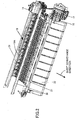
- FIG. 2 is an external view showing major portions of the inkjet recording device 10 shown in FIG. 1 .
- FIG. 2 shows an interior portion of the inkjet recording device 10, where a front cover indicated by the reference numeral 23 in FIG. 3 has been removed from the inkjet recording device 10.
- the front cover 23 forms a part of exterior panels of the inkjet recording device 10.
- FIG. 2 shows a state where the carriage 14 shown in FIG. 1 is disposed at a home position prior to the carriage 14 being moved in a main scanning direction.
- One end portions of the tubes 19 in an extended direction in which the tubes 19 are extended are connected to and fixed to the corresponding sub-tanks mounted on the carriage 14.
- the tubes 19 are folded at corresponding middle portions in the extended direction.
- the middle portions are in parallel with a sheet conveyance direction in which the sheet of recording paper 20 is conveyed.
- the tubes 19 have a U-shape in planar view.
- the other end portions of the tubes 19 in the extended direction are connected to and fixed to the corresponding ink cartridges 11.
- the ink cartridges 11 serve as the main tanks.
- a platen 21 is disposed below the carriage 14.
- the sheet of recording paper 20 moves on the platen 21.
- a paper discharging guide 22 is disposed downstream the platen 21 in the sheet conveyance direction.
- the paper discharging guide 22 is slanted downward so that free fall of the sheet of recording paper 20 by its own weight can be utilized.
- the extended portions of the tubes 19 are supported by corresponding tube guides 30 and 31.
- the tube guide 30 is disposed downstream the tube guide 31 in the conveyance direction in which the sheet of recording paper 20 is conveyed (cf. FIG. 1 ).
- the tube guide 31 is disposed upstream the tube guide 30 in the sheet conveyance direction.
- the tube guides 30 and 31 are facing each other. Namely, one folded end portions of the tubes 19 (corresponding to a position of one portion of the U-shape, which is formed by the folded tubes 19) are supported by the tube guide 30, and the other folded end portions (corresponding to a position of the other portion of the U-shape) of the tubes 19 are supported by the tube guide 31.
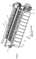
- FIG. 3 shows a state where a front cover 23 is disposed above the paper discharging guide 22 shown in FIG. 2 .
- the front cover 23 can be opened and closed in the upward direction. When paper jamming occurs, the front cover 23 is opened to remove the sheet of recording paper 20.
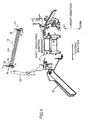
- FIG. 4 shows the major portions of the image recording device 10 of FIG. 2 that are viewed from a side of the carriage 14.
- the extended portions of the tubes 19 are disposed at corresponding end portions of a folded portion 19A of the tubes 19.
- the extended portions of the tubes 19 are supported by the corresponding first and second tube guides 30 and 31.
- the first guide 30 disposed at the downstream position in the sheet conveyance direction faces the second guide 31
- the second guide 31 disposed at the upstream position in the sheet conveyance direction faces the first guide 30.
- the first guide 30 is disposed at a side of the paper discharging guide 22 at which the sheet of recording paper 20 is received. Namely, the first guide 30 is disposed at the downstream position in the sheet conveyance direction. The position of the first tube guide 30 is higher in a height direction than that of the second tube guide 31 facing the first tube guide 30, thereby defining a vertical positional relationship between the first tube guide 30 and the second tube guide 31.
- the arrows indicating the height direction are provided with indications of "UP" and "DOWN” to imply that the vertical positional relationship has been defined in the height direction.
- a space between a horizontal surface on the platen 21 and the first tube guide 30, especially, a space H2 that is ensured by the distance in the height direction is enlarged, compared to that of indicated by the reference symbol H1 in FIG. 10 in the case where the tube guides 30 and 31 are arranged exactly horizontally.
- the space is enlarged for the operator for inserting the hand to remove the sheet of recording paper 20 that has caused the conveyance failure such as the paper jamming on the platen 21, thereby facilitating the removing operation of the sheet of recording paper 20.
- the expansion of the space is ensured by defining the vertical positional relationship between the first and second tube guides 30 and 31.
- the tubes 19 are slanted, and the tubes 19 are in a condition where the tubes 19 are easily slipped out from the first and second tube guides 30 and 31. Namely, such slipping out of the tubes 19 is caused by the structures of the first and second tube guides 30 and 31.
- the line from the first tube guide 30 to the second tube guide 31 is slanted with respect to the horizontal line.
- the line is not exactly horizontal so that the first and second tube guides 30 and 31 have the vertical positional relationship. Therefore, for the first and second tube guides 30 and 31, specific supporting structures for supporting the tubes 19 have been adopted so as to respond to the slant.
- FIGS. 6 and 7 show the supporting structures of the tubes 19.
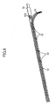
- the tubes 19 are supported by the first and second tube guides 30 and 31 by the structure shown in FIG. 8 .
- the plural tubes 19 are arranged in parallel in the height direction so as to supply the corresponding colors of ink droplets.
- the tubes 19 are fixed to a sheet member 32 while bundled by clamp members 33.
- the sheet member 32 is arranged along a surface of the tubes 19 that faces the first and second tube guides 30 and 31.
- the sheet member 32 is formed of an elastic thin plate-shaped member.
- the sheet member 32 faces the extended portions of the tubes 19 and the folded portion 19A.
- the clamp members 33 are disposed between the fixed end portions of the tubes 19 at the side of the carriage 14 and the fixed end portions of the tubes 19 at the side of the ink cartridges 11. The clamp members 33 fix the tubes 19 to the sheet member 32.
- the sheet member 32 that faces the tubes 19 is disposed throughout the extended direction, the surface of the tubes 19 that faces the first and second tube guides 30 and 31 does not directly contact the first and second tube guides 30 and 31.
- the cross-section of the clamp member 33 has a channel-like shape.
- the clamp member 33 is attached to the sheet member 32 by engaging hook-shaped portions of the clamp member 33 to corresponding engaging holes 32A of the sheet member 32.
- a longitudinal direction of the engaging hole 32A of the sheet member 32 is set to be the direction in which the sheet member 32 is extended.
- the clamp member 33 engaged to the corresponding engaging hole 32A can be slid in the longitudinal direction. Since the clamp members 33 are slidable, when the clamp members 33 are disposed along the extended direction of the tubes 19 while the clamp members 33 are evenly spaced apart, positional shifts of the corresponding clamp members 33 can be corrected.
- the disposed positions of the first and second tube guides 30 and 31 in the height direction are different so that the vertical positional relationship is defined. Therefore, taking into consideration that the folded portion 19A is oblique, the first tube guide 30 is formed of a metal component including an upright portion 30A arranged along the height direction as a portion that faces the upper portion of the sheet member 32; and a lateral portion 30B as a portion that faces the lower portion of the sheet member 32.
- the lateral portion 30B is arranged so that an angle between the upright portion 30A and the lateral portion 30B is an obtuse angle (the angle indicated by the symbol ⁇ in FIG. 6 ).
- the second tube guide 31 is formed of a metal component including an upright portion 31A arranged along the height direction as a portion that faces the upper portion of the sheet member 32; and a lateral portion 31B as a portion that faces the lower portion of the sheet member 32.
- the lateral portion 31B is arranged so that an angle between the upright portion 31A and the lateral portion 31B is an obtuse angle (the angle indicated by the symbol ⁇ in FIG. 7 ).
- the first tube guide 30 is formed of a single plate member that has been bent in the obtuse angle.
- the second tube guide 31 is formed of a single plate member that has been bent in the obtuse angle.
- the number of the bent portions of the first tube guide 30 is greater than the number of the bent portions of the second tube guide 31.
- the lower end in the height direction of the sheet member 32 which is slanted due to holding the slanted tubes 19, can contact the lateral portions 30B and 31B of the corresponding tube guides 30 and 31. Additionally, the upper end in the height direction of the slanted sheet member 32 can contact the upright portions 30A and 31A of the corresponding tube guides 30 and 31.
- the pressing force of the sheet member 32 to contact the corresponding portions of the tube guides 30 and 31 is obtained by the shape restoring force due to the elasticity generated by folding the sheet member 32 at the middle portion in the extended direction. Namely, the pressing force is obtained by utilizing the restoring force of the sheet member 32 to recover its original linear shape. Therefore, by the pressing force in the horizontal direction caused by the shape restoring force and the gravitational force, the sheet member 32 contacts the upright portion 30A along the height direction and the lateral portion 30B of the first tube guide 30 at the positions shown by the corresponding black dots in FIG. 6 . Additionally, the sheet member 32 contacts the upright portion 31A along the height direction and the lateral portion 31B of the second tube guide 31 at the positions shown by the corresponding black dots in FIG. 7 . Here, the sheet member 32 remains movable while contacting the first and second tube guides 30 and 31 at the positions indicated by the corresponding black dots.
- a film or sheet 34 for reducing sliding friction is attached to the upright portion 30A and the lateral portion 30B of the first tube guide 30 which are contacted by the sheet member 32.
- a film or sheet 35 for reducing the sliding friction is attached to the upright portion 31A and the lateral portion 31B of the second tube guide 31 which are also contacted by the sheet member 32.
- the film or sheet 34 is extended from the lateral portion 30B to the upright portion 30A of the first tube guide 30 so as to cover both the upright portion 30A and the lateral portion 30B.
- the film or sheet 34 is extended along the lateral portion 30B.
- the film or sheet 34 is bent at a position on the lateral portion 30B corresponding to a middle position of a line along the lateral portion 30B that reaches the upright portion 30A, and the film or sheet 34 reaches a part of the upright portion 30A.
- the film or sheet 35 is extended from the lateral portion 31B to the upright portion 31A of the second tube guide 31 so as to cover both the upright portion 31A and the lateral portion 31B.
- the film or sheet 35 is extended along the lateral portion 31B.
- the film or sheet 35 is bent at a position on the lateral portion 31B corresponding to a middle position of a line along the lateral portion 31B that reaches the upright portion 31A, and the film or sheet 35 reaches a part of the upright portion 31A.
- the friction to the sheet member 32 is reduced, when the sheet member 32 is moved on the surfaces of the first and second tube guides 30 and 31.
- the sheet member 32 is pressed toward the corresponding portions of the first and the second tube guides 30 and 31 by the shape restoring force.
- first and second tube guides 30 and 31 especially, since a tip of the lateral portion 30B is directed downward in the first tube guide 30 arranged at the higher position in the height direction, it is possible that the sheet member 32 is slipped out from the lateral portion 30B.
- intentional separation of the tubes 19 from the tube guides 30 and 31 for removing the sheet of recording paper 20 that has caused a conveyance failure and unintentional contact by a hand of an operator can be considered as the causes of the slipping out.
- the reaction force is utilized to restore the tubes 19 that have slipped out from the first and second tube guides 30 and 31 to the original positions.
- the reaction force increases as the distance between the fixed positions of the tubes 19 and the point of action of the load corresponding to the slipped out portion becomes shorter.
- FIG. 9 shows this state.
- the folded portion 19A of the tubes 19 is separated from the first and the second tube guides 30 and 31.
- the folded portion 19A is disposed at a position separated from the fixed positions of the tubes 19 and the positions of the tubes 19 in the extended direction where the corresponding end portions of the tubes 19 are supported by the sheet member 32.
- the fixed positions of the tubes 19 correspond to the end portions of the tubes 19 in the extended direction, namely, the side of the sub-tank 15 and the side of the ink cartridge 11.
- the sheet member 32 tends to return the slipped out portion to the position along the extended direction by the shape restoring force generated by the elasticity. Namely, when the pressing force of the sheet member 32 to press toward the first and second tube guides 30 and 31 is greater than the force to slip out, the slipped out portion of the sheet member 32 tends to return to the position along the extended direction.
- the force generated at the sides of the fixed positions of the tubes 19 may be regarded as action of the reaction force that acts on a beam.
- an amount of the deformation (separated amount) at the point of action of the load is constant and if the carriage 14 and the folded portion 19A that has slipped out are assumed to be the beam, the length of the whole beam (the distance between the point of action of the load and the fixed points) varies as the carriage 14 moves. In this case, the length of the whole beam is shortened. Accordingly, the reaction force of the sheet 32 increases depending on the position of the carriage 14, as the carriage 14 moves.
- the direction of the folded portion 19A changes from the direction in which the folded portion 19 has slipped out to the extended direction, and thereby the position of the sheet member 32 is returned to its original position along the first and second tube guides 30 and 31.
- the folded portion 19A of the tubes 19 that has slipped out returns to the position along the extended direction, where the extended portions of the tubes 19 are arranged along the first and second tube guides 30 and 31. In this manner, the original positions of the tubes 19 are restored from the slipped out state.
- the resistance during moving the carriage 14 is prevented from increasing, and thereby the smooth movement of the carriage 14 is maintained.
- the resistance is due to the state of the tubes 19, such as the state where the tubes 19 that have slipped out contact a peripheral portion or the state where the tubes 19 are removed and dropped, other than the state where the tubes 19 are guided by the first and the second guides 30 and 31.
- the tubes that have slipped out from the first and second tube guides 30 and 31 can be returned to their original positions by using the increase of the reaction force in the sheet member 32. Therefore, the smooth movement of the carriage 14 can be maintained without providing special guide members to prevent the tubes from slipping out.
Landscapes
- Ink Jet (AREA)
Claims (6)
- Bilderzeugungsvorrichtung (10), die aufweist:einen Schlitten bzw. Wagen (14), der konfiguriert ist, um in einer Hauptabtastrichtung bewegt zu werden, wobei der Schlitten bzw. Wagen eine Vielzahl von Aufzeichnungsköpfen (13), die konfiguriert sind, um Flüssigkeitströpfchen abzuführen bzw. auszustoßen oder freizusetzen, und Sub-Tanks bzw. Untertanks (14) einschließt bzw. beinhaltet, die konfiguriert sind um entsprechende Flüssigkeiten, die zuzuführen sind, zu speichern;eine Trägerplatte (21), die an einer Position angeordnet ist, die den Düsenflächen der Aufzeichnungsköpfe des Schlittens bzw. Wagens gegenüberliegt, und eine Beförderungsfläche zum Befördern eines Aufzeichnungsmediums (20) aufweist, wobei ein Bild auf dem Aufzeichnungsmedium ausgebildet ist, und zwar durch das Abführen bzw. Ausstoßen oder Freisetzen der Flüssigkeitströpfchen auf das Aufzeichnungsmedium;flexible Rohre bzw. Kanäle (19), die erste und zweite Endabschnitte, die sich entlang der Hauptabtastrichtung oberhalb bzw. über der Trägerplatte erstrecken und mittlere Abschnitte aufweisen, die parallel mit bzw. zu einer Richtung sind, die senkrecht zu der Hauptabtastrichtung ist, wobei die ersten Endabschnitten an die korrespondierenden Sub-Tanks bzw. Untertanks angeschlossen sind, und die zweiten Endabschnitte an die korrespondierenden Haupttanks angeschlossen sind, die konfiguriert sind, um korrespondierende Flüssigkeiten zu speichern, die zu den korrespondierenden Sub-Tanks bzw. Untertanks zuzuführen sind;dadurch gekennzeichnet, dass die Vorrichtung weiter aufweist:erste und zweite Rohrführungen bzw. Kanalführungen (30, 31), die konfiguriert sind, um Abschnitte der flexiblen Rohre bzw. Kanäle an einer ersten Seite der ersten Endabschnitte und Abschnitte der flexiblen Rohre an einer zweiten Seite der zweiten Endabschnitte zu stützen bzw. zu tragen, und zwar jeweilig, wobei die flexiblen Rohre bzw. Kanäle in einer Höhenrichtung angeordnet sind;wobei die erste Rohrführung bzw. Kanalführung (30) an einem ersten Abschnitt angeordnet ist, und die zweite Rohrführung bzw. Kanalführung (31) an einer zweiten Position angeordnet ist, wobei die erste Position höher als die zweite Position in einer Höhenrichtung ist und die erste Position näher an einem Abschnitt (22) der Bilderzeugungsvorrichtung von welcher beim Verwenden das Aufzeichnungsmedium abgeführt bzw. ausgestoßen oder freigesetzt ist, als die zweite Position, undwobei die Rohre bzw. Kanäle durch ein plattenähnliches Blattglied (32) getragen bzw. gestützt ist, das aus einem elastischen Material geformt ist, das dünne plattenähnliche Blattglied zwischen den Rohren bzw. Kanälen und den ersten und zweiten Rohrführungen bzw. Kanalführungen angeordnet sind, wobei die Rohre bzw. Kanäle an das dünne plattenähnliche Blattglied befestigt sind, und zwar in einer Richtung in welcher die Rohre bzw. Kanäle sich durch Halterungsglieder bzw. Klammerglieder (33) erstrecken, die an vielen Position in einer ersten Nähe der ersten Endabschnitte und in einer zweiten Nähe der zweiten Endabschnitte angeordnet sind, die erste Rohrführung bzw. Kanalführung (30) stromabwärts der zweiten Rohrführung bzw. Kanalführung (31) angeordnet ist, und zwar in einer Richtung, die senkrecht zu der Hauptabtastrichtung ist, und die ersten und zweiten Rohrführungen bzw. Kanalführungen (30, 31) sich gegenüberliegen bzw. einander gegenüberliegen,wobei die erste Rohrführung bzw. Kanalführung (30) eine Metallkomponente aufweist, die einen vertikalen bzw. aufrechten Abschnitt (30A), der entlang der Höhenrichtung angeordnet ist und einen Querabschnitt bzw. seitlichen Abschnitt (30B) einschließt bzw. beinhaltet, der angeordnet ist, so dass ein Winkel zwischen dem vertikalen bzw. aufrechten Abschnitt (30A) und dem Querabschnitt bzw. seitlichen Abschnitt (30B) ein stumpfer Winkel ist, wobei die zweite Rohrführung bzw. Kanalführung (31) eine Metallkomponente aufweist, die einen vertikalen bzw. aufrechten Abschnitt (31A), der entlang der Höhenrichtung angeordnet ist, und einen Querabschnitt bzw. seitlichen Abschnitt (31B) einschließt bzw. beinhaltet, der angeordnet ist, so dass ein Winkel zwischen dem vertikalen bzw. aufrechten Abschnitt (31A) und dem Querabschnitt bzw. seitlichen Abschnitt (31B) ein stumpfer Winkel ist, und die ersten und zweiten Rohrführungen bzw. Kanalführungen jeweiligen Abschnitten des Blattgliedes gegenüberliegen, undwobei die Rohre bzw. Kanäle geneigt bzw. abgeschrägt oder schief sind, und das untere Ende in der Höhenrichtung des Blattgliedes (32), welches geneigt bzw. abgeschrägt oder schief aufgrund des Haltens der geneigten bzw. abgeschrägten oder schiefen Rohre (19) ist, die Querabschnitte bzw. seitlichen Abschnitte (30B, 31B) der korrespondierenden ersten und zweiten Rohrführungen bzw. Kanalführungen (30, 31) berührt, und das obere Ende in der Höhenrichtung des geneigten bzw. abgeschrägten oder schiefen Blattgliedes (32) die vertikale bzw. aufrechte Abschnitte (30A, 31A) der korrespondierenden ersten und zweiten Rohrführungen bzw. Kanalführungen (30, 31) berührt.
- Bilderzeugungsvorrichtung nach Anspruch 1,
wobei ein erster Film bzw. eine erste Dünnschicht oder ein erstes Blatt (34), der bzw. das konfiguriert ist, um die Gleitreibung zu reduzieren, an eine erste Fläche der ersten Rohrführung bzw. Kanalführung angebracht ist, wobei Endabschnitte in der Höhenrichtung des dünnen plattenähnlichen Blattgliedes die erste Fläche berührt bzw. kontaktiert, und
wobei ein zweiter Film bzw. eine zweite Dünnschicht oder ein zweites Blatt (35), der bzw. das konfiguriert ist, um die Gleitreibung zu reduzieren, an einer zweiten Fläche der zweiten Rohrführung bzw. Kanalführung angebracht ist, wobei die Endabschnitte in der Höhenrichtung des dünnen plattenähnlichen Blattgliedes die zweite Fläche berührt bzw. kontaktiert. - Bilderzeugungsvorrichtung nach Anspruch 1, wobei das dünne plattenähnliche Blattglied gegen eine erste Fläche der ersten Rohrführung bzw. Kanalführung und eine zweite Fläche der zweiten Rohrführung bzw. Kanalführung gleitbar ist.
- Bilderzeugungsvorrichtung nach Anspruch 2, wobei das dünne plattenähnliche Blattglied gegen die erste Fläche der ersten Rohrführung bzw. Kanalführung und der zweiten Fläche die zweite Rohrführung bzw. Kanalführung gleitbar ist.
- Bilderzeugungsvorrichtung nach irgendeinem der Ansprüche 1 bis 4,
wobei die Rohre bzw. Kanäle an den ersten und zweiten Rohrführungen bzw. Kanalführungen angebracht sind, und zwar derart, dass die Rohre bzw. Kanäle den ersten und zweiten Rohrführungen bzw. Kanalführungen in einer Richtung, welche nicht horizontal ist, gegenüberliegen. - Bilderzeugungsvorrichtung nach irgendeinem der Ansprüche 1 bis 5,
wobei die ersten und zweiten Rohrführungen bzw. Kanalführungen sich entlang der Hauptabtastrichtung erstrecken.
Applications Claiming Priority (1)
| Application Number | Priority Date | Filing Date | Title |
|---|---|---|---|
| JP2011257096A JP5919758B2 (ja) | 2011-11-25 | 2011-11-25 | 画像形成装置 |
Publications (2)
| Publication Number | Publication Date |
|---|---|
| EP2596953A1 EP2596953A1 (de) | 2013-05-29 |
| EP2596953B1 true EP2596953B1 (de) | 2015-04-08 |
Family
ID=47278652
Family Applications (1)
| Application Number | Title | Priority Date | Filing Date |
|---|---|---|---|
| EP12191291.9A Not-in-force EP2596953B1 (de) | 2011-11-25 | 2012-11-05 | Bilderzeugungsvorrichtung |
Country Status (4)
| Country | Link |
|---|---|
| US (1) | US8770728B2 (de) |
| EP (1) | EP2596953B1 (de) |
| JP (1) | JP5919758B2 (de) |
| CN (1) | CN103129154B (de) |
Families Citing this family (4)
| Publication number | Priority date | Publication date | Assignee | Title |
|---|---|---|---|---|
| WO2017108094A1 (en) * | 2015-12-22 | 2017-06-29 | Hewlett-Packard Development Company, L.P. | Printing fluid cartridge for a pumped printing fluid system |
| JP7292323B2 (ja) * | 2021-04-13 | 2023-06-16 | ローランドディー.ジー.株式会社 | プリンタ |
| CN113617680A (zh) * | 2021-08-13 | 2021-11-09 | 东北大学秦皇岛分校 | 一种基于机器人进行密度估计的矿石分选装置及方法 |
| JP2023122794A (ja) * | 2022-02-24 | 2023-09-05 | ローランドディー.ジー.株式会社 | プリンタ |
Family Cites Families (22)
| Publication number | Priority date | Publication date | Assignee | Title |
|---|---|---|---|---|
| JPS60232964A (ja) * | 1984-05-04 | 1985-11-19 | Canon Inc | 液体噴射記録装置 |
| EP0598701B1 (de) | 1986-12-10 | 1998-03-25 | Canon Kabushiki Kaisha | Aufzeichnungsgerät und Entladungsregeneriermethode |
| JP2641200B2 (ja) | 1986-12-10 | 1997-08-13 | キヤノン株式会社 | インクジェット記録装置 |
| JPH01176565A (ja) * | 1987-12-29 | 1989-07-12 | Canon Inc | インクジェット記録装置 |
| US5473354A (en) * | 1994-05-26 | 1995-12-05 | Hewlett-Packard Company | Ink-delivery apparatus |
| US5602577A (en) * | 1994-07-21 | 1997-02-11 | Hewlett-Packard Company | Humidifier apparatus for fluid-containing tubes and an improved ink-jet printer utilizing the apparatus |
| US6007190A (en) * | 1994-12-29 | 1999-12-28 | Encad, Inc. | Ink supply system for an ink jet printer having large volume ink containers |
| US6068370A (en) * | 1996-08-30 | 2000-05-30 | Hewlett-Packard Company | Fluidic delivery system with tubing and manifolding for an off-axis printing system |
| JP4468495B2 (ja) * | 1998-03-31 | 2010-05-26 | ブラザー工業株式会社 | 印字装置 |
| US6247802B1 (en) * | 1999-01-29 | 2001-06-19 | Hewlett-Packard Company | Ink supply tube guiding system for large format printer |
| US7273271B2 (en) * | 2002-02-28 | 2007-09-25 | Seiko Epson Corporation | Liquid supplying member, method of manufacturing the same, and liquid ejection apparatus incorporating the same |
| US7201475B2 (en) * | 2002-02-28 | 2007-04-10 | Seiko Epson Corporation | Liquid supplying member, method of manufacturing the same, and liquid ejection apparatus incorporating the same |
| US6739698B2 (en) * | 2002-09-11 | 2004-05-25 | Lexmark International, Inc. | Off-carrier tubing layout |
| JP2005035032A (ja) * | 2003-07-16 | 2005-02-10 | Seiko Epson Corp | インクジェット式記録装置及び液体噴射装置 |
| JP2005088524A (ja) * | 2003-09-19 | 2005-04-07 | Canon Inc | 画像形成装置 |
| JP2007176068A (ja) | 2005-12-28 | 2007-07-12 | Brother Ind Ltd | 画像記録装置 |
| US7775629B2 (en) | 2005-12-28 | 2010-08-17 | Brother Kogyo Kabushiki Kaisha | Image recording apparatus |
| JP4797626B2 (ja) | 2005-12-28 | 2011-10-19 | ブラザー工業株式会社 | 画像記録装置 |
| JP4671884B2 (ja) | 2006-02-20 | 2011-04-20 | 株式会社リコー | 画像形成装置 |
| JP4187007B2 (ja) * | 2006-04-28 | 2008-11-26 | ブラザー工業株式会社 | 画像記録装置 |
| JP4329808B2 (ja) * | 2006-11-13 | 2009-09-09 | セイコーエプソン株式会社 | 液体供給装置及び液体噴射装置 |
| JP2008149647A (ja) | 2006-12-20 | 2008-07-03 | Seiko Epson Corp | 流体供給装置 |
-
2011
- 2011-11-25 JP JP2011257096A patent/JP5919758B2/ja not_active Expired - Fee Related
-
2012
- 2012-11-05 EP EP12191291.9A patent/EP2596953B1/de not_active Not-in-force
- 2012-11-06 US US13/669,683 patent/US8770728B2/en active Active
- 2012-11-22 CN CN201210480791.3A patent/CN103129154B/zh active Active
Also Published As
| Publication number | Publication date |
|---|---|
| US20130135414A1 (en) | 2013-05-30 |
| JP2013111762A (ja) | 2013-06-10 |
| EP2596953A1 (de) | 2013-05-29 |
| JP5919758B2 (ja) | 2016-05-18 |
| US8770728B2 (en) | 2014-07-08 |
| CN103129154A (zh) | 2013-06-05 |
| CN103129154B (zh) | 2015-05-20 |
Similar Documents
| Publication | Publication Date | Title |
|---|---|---|
| EP2021184B1 (de) | Papierfördervorrichtung, bildgebungsvorrichtung und tintenstrahlaufzeichnungsvorrichtung | |
| JP5786681B2 (ja) | インクジェット記録装置 | |
| JP4277223B2 (ja) | 給紙装置及びそれを備えた画像記録装置 | |
| CN103129130B (zh) | 喷墨记录设备 | |
| US8770717B2 (en) | Image forming apparatus including carriage that mounts image forming unit | |
| JP4551499B2 (ja) | 画像形成装置 | |
| CN103129134A (zh) | 喷墨记录装置 | |
| EP2596953B1 (de) | Bilderzeugungsvorrichtung | |
| US8075130B2 (en) | Work device and image recording apparatus equipped with the work device | |
| JP5223750B2 (ja) | 画像形成装置 | |
| US7547091B2 (en) | Recording apparatus and liquid ejecting apparatus | |
| JP4919731B2 (ja) | 画像形成装置 | |
| JP2009126144A (ja) | 画像形成装置 | |
| US8038287B2 (en) | Image recording devices | |
| JP4224718B2 (ja) | 給紙装置 | |
| JP2012152993A (ja) | インクジェット記録装置 | |
| JP6229449B2 (ja) | 記録装置 | |
| JP5821312B2 (ja) | インクジェット記録装置 | |
| JP5910921B2 (ja) | 画像形成装置 | |
| JP2007290801A (ja) | インクジェットプリンタ及び画像形成装置 | |
| JP2015098369A (ja) | 記録装置 |
Legal Events
| Date | Code | Title | Description |
|---|---|---|---|
| PUAI | Public reference made under article 153(3) epc to a published international application that has entered the european phase |
Free format text: ORIGINAL CODE: 0009012 |
|
| 17P | Request for examination filed |
Effective date: 20121105 |
|
| AK | Designated contracting states |
Kind code of ref document: A1 Designated state(s): AL AT BE BG CH CY CZ DE DK EE ES FI FR GB GR HR HU IE IS IT LI LT LU LV MC MK MT NL NO PL PT RO RS SE SI SK SM TR |
|
| AX | Request for extension of the european patent |
Extension state: BA ME |
|
| GRAP | Despatch of communication of intention to grant a patent |
Free format text: ORIGINAL CODE: EPIDOSNIGR1 |
|
| RIC1 | Information provided on ipc code assigned before grant |
Ipc: B41J 2/175 20060101AFI20140923BHEP |
|
| INTG | Intention to grant announced |
Effective date: 20141029 |
|
| RAP1 | Party data changed (applicant data changed or rights of an application transferred) |
Owner name: RICOH COMPANY, LTD. |
|
| GRAS | Grant fee paid |
Free format text: ORIGINAL CODE: EPIDOSNIGR3 |
|
| GRAA | (expected) grant |
Free format text: ORIGINAL CODE: 0009210 |
|
| AK | Designated contracting states |
Kind code of ref document: B1 Designated state(s): AL AT BE BG CH CY CZ DE DK EE ES FI FR GB GR HR HU IE IS IT LI LT LU LV MC MK MT NL NO PL PT RO RS SE SI SK SM TR |
|
| REG | Reference to a national code |
Ref country code: GB Ref legal event code: FG4D |
|
| REG | Reference to a national code |
Ref country code: CH Ref legal event code: EP |
|
| REG | Reference to a national code |
Ref country code: IE Ref legal event code: FG4D |
|
| REG | Reference to a national code |
Ref country code: AT Ref legal event code: REF Ref document number: 720223 Country of ref document: AT Kind code of ref document: T Effective date: 20150515 |
|
| REG | Reference to a national code |
Ref country code: DE Ref legal event code: R096 Ref document number: 602012006454 Country of ref document: DE Effective date: 20150521 |
|
| REG | Reference to a national code |
Ref country code: AT Ref legal event code: MK05 Ref document number: 720223 Country of ref document: AT Kind code of ref document: T Effective date: 20150408 |
|
| REG | Reference to a national code |
Ref country code: NL Ref legal event code: VDEP Effective date: 20150408 |
|
| REG | Reference to a national code |
Ref country code: LT Ref legal event code: MG4D |
|
| PG25 | Lapsed in a contracting state [announced via postgrant information from national office to epo] |
Ref country code: NL Free format text: LAPSE BECAUSE OF FAILURE TO SUBMIT A TRANSLATION OF THE DESCRIPTION OR TO PAY THE FEE WITHIN THE PRESCRIBED TIME-LIMIT Effective date: 20150408 |
|
| PG25 | Lapsed in a contracting state [announced via postgrant information from national office to epo] |
Ref country code: LT Free format text: LAPSE BECAUSE OF FAILURE TO SUBMIT A TRANSLATION OF THE DESCRIPTION OR TO PAY THE FEE WITHIN THE PRESCRIBED TIME-LIMIT Effective date: 20150408 Ref country code: ES Free format text: LAPSE BECAUSE OF FAILURE TO SUBMIT A TRANSLATION OF THE DESCRIPTION OR TO PAY THE FEE WITHIN THE PRESCRIBED TIME-LIMIT Effective date: 20150408 Ref country code: PT Free format text: LAPSE BECAUSE OF FAILURE TO SUBMIT A TRANSLATION OF THE DESCRIPTION OR TO PAY THE FEE WITHIN THE PRESCRIBED TIME-LIMIT Effective date: 20150810 Ref country code: FI Free format text: LAPSE BECAUSE OF FAILURE TO SUBMIT A TRANSLATION OF THE DESCRIPTION OR TO PAY THE FEE WITHIN THE PRESCRIBED TIME-LIMIT Effective date: 20150408 Ref country code: NO Free format text: LAPSE BECAUSE OF FAILURE TO SUBMIT A TRANSLATION OF THE DESCRIPTION OR TO PAY THE FEE WITHIN THE PRESCRIBED TIME-LIMIT Effective date: 20150708 Ref country code: HR Free format text: LAPSE BECAUSE OF FAILURE TO SUBMIT A TRANSLATION OF THE DESCRIPTION OR TO PAY THE FEE WITHIN THE PRESCRIBED TIME-LIMIT Effective date: 20150408 |
|
| REG | Reference to a national code |
Ref country code: FR Ref legal event code: PLFP Year of fee payment: 4 |
|
| PG25 | Lapsed in a contracting state [announced via postgrant information from national office to epo] |
Ref country code: IS Free format text: LAPSE BECAUSE OF FAILURE TO SUBMIT A TRANSLATION OF THE DESCRIPTION OR TO PAY THE FEE WITHIN THE PRESCRIBED TIME-LIMIT Effective date: 20150808 Ref country code: GR Free format text: LAPSE BECAUSE OF FAILURE TO SUBMIT A TRANSLATION OF THE DESCRIPTION OR TO PAY THE FEE WITHIN THE PRESCRIBED TIME-LIMIT Effective date: 20150709 Ref country code: AT Free format text: LAPSE BECAUSE OF FAILURE TO SUBMIT A TRANSLATION OF THE DESCRIPTION OR TO PAY THE FEE WITHIN THE PRESCRIBED TIME-LIMIT Effective date: 20150408 Ref country code: RS Free format text: LAPSE BECAUSE OF FAILURE TO SUBMIT A TRANSLATION OF THE DESCRIPTION OR TO PAY THE FEE WITHIN THE PRESCRIBED TIME-LIMIT Effective date: 20150408 Ref country code: LV Free format text: LAPSE BECAUSE OF FAILURE TO SUBMIT A TRANSLATION OF THE DESCRIPTION OR TO PAY THE FEE WITHIN THE PRESCRIBED TIME-LIMIT Effective date: 20150408 |
|
| REG | Reference to a national code |
Ref country code: DE Ref legal event code: R097 Ref document number: 602012006454 Country of ref document: DE |
|
| PG25 | Lapsed in a contracting state [announced via postgrant information from national office to epo] |
Ref country code: EE Free format text: LAPSE BECAUSE OF FAILURE TO SUBMIT A TRANSLATION OF THE DESCRIPTION OR TO PAY THE FEE WITHIN THE PRESCRIBED TIME-LIMIT Effective date: 20150408 Ref country code: DK Free format text: LAPSE BECAUSE OF FAILURE TO SUBMIT A TRANSLATION OF THE DESCRIPTION OR TO PAY THE FEE WITHIN THE PRESCRIBED TIME-LIMIT Effective date: 20150408 |
|
| PLBE | No opposition filed within time limit |
Free format text: ORIGINAL CODE: 0009261 |
|
| STAA | Information on the status of an ep patent application or granted ep patent |
Free format text: STATUS: NO OPPOSITION FILED WITHIN TIME LIMIT |
|
| PG25 | Lapsed in a contracting state [announced via postgrant information from national office to epo] |
Ref country code: CZ Free format text: LAPSE BECAUSE OF FAILURE TO SUBMIT A TRANSLATION OF THE DESCRIPTION OR TO PAY THE FEE WITHIN THE PRESCRIBED TIME-LIMIT Effective date: 20150408 Ref country code: PL Free format text: LAPSE BECAUSE OF FAILURE TO SUBMIT A TRANSLATION OF THE DESCRIPTION OR TO PAY THE FEE WITHIN THE PRESCRIBED TIME-LIMIT Effective date: 20150408 Ref country code: SK Free format text: LAPSE BECAUSE OF FAILURE TO SUBMIT A TRANSLATION OF THE DESCRIPTION OR TO PAY THE FEE WITHIN THE PRESCRIBED TIME-LIMIT Effective date: 20150408 Ref country code: RO Free format text: LAPSE BECAUSE OF NON-PAYMENT OF DUE FEES Effective date: 20150408 |
|
| 26N | No opposition filed |
Effective date: 20160111 |
|
| PG25 | Lapsed in a contracting state [announced via postgrant information from national office to epo] |
Ref country code: IT Free format text: LAPSE BECAUSE OF FAILURE TO SUBMIT A TRANSLATION OF THE DESCRIPTION OR TO PAY THE FEE WITHIN THE PRESCRIBED TIME-LIMIT Effective date: 20150408 |
|
| PG25 | Lapsed in a contracting state [announced via postgrant information from national office to epo] |
Ref country code: SI Free format text: LAPSE BECAUSE OF FAILURE TO SUBMIT A TRANSLATION OF THE DESCRIPTION OR TO PAY THE FEE WITHIN THE PRESCRIBED TIME-LIMIT Effective date: 20150408 |
|
| PG25 | Lapsed in a contracting state [announced via postgrant information from national office to epo] |
Ref country code: LU Free format text: LAPSE BECAUSE OF FAILURE TO SUBMIT A TRANSLATION OF THE DESCRIPTION OR TO PAY THE FEE WITHIN THE PRESCRIBED TIME-LIMIT Effective date: 20151105 Ref country code: MC Free format text: LAPSE BECAUSE OF FAILURE TO SUBMIT A TRANSLATION OF THE DESCRIPTION OR TO PAY THE FEE WITHIN THE PRESCRIBED TIME-LIMIT Effective date: 20150408 |
|
| REG | Reference to a national code |
Ref country code: CH Ref legal event code: PL |
|
| PG25 | Lapsed in a contracting state [announced via postgrant information from national office to epo] |
Ref country code: CH Free format text: LAPSE BECAUSE OF NON-PAYMENT OF DUE FEES Effective date: 20151130 Ref country code: LI Free format text: LAPSE BECAUSE OF NON-PAYMENT OF DUE FEES Effective date: 20151130 |
|
| REG | Reference to a national code |
Ref country code: IE Ref legal event code: MM4A |
|
| PG25 | Lapsed in a contracting state [announced via postgrant information from national office to epo] |
Ref country code: BE Free format text: LAPSE BECAUSE OF FAILURE TO SUBMIT A TRANSLATION OF THE DESCRIPTION OR TO PAY THE FEE WITHIN THE PRESCRIBED TIME-LIMIT Effective date: 20150408 |
|
| PG25 | Lapsed in a contracting state [announced via postgrant information from national office to epo] |
Ref country code: IE Free format text: LAPSE BECAUSE OF NON-PAYMENT OF DUE FEES Effective date: 20151105 |
|
| REG | Reference to a national code |
Ref country code: FR Ref legal event code: PLFP Year of fee payment: 5 |
|
| PG25 | Lapsed in a contracting state [announced via postgrant information from national office to epo] |
Ref country code: SM Free format text: LAPSE BECAUSE OF FAILURE TO SUBMIT A TRANSLATION OF THE DESCRIPTION OR TO PAY THE FEE WITHIN THE PRESCRIBED TIME-LIMIT Effective date: 20150408 Ref country code: HU Free format text: LAPSE BECAUSE OF FAILURE TO SUBMIT A TRANSLATION OF THE DESCRIPTION OR TO PAY THE FEE WITHIN THE PRESCRIBED TIME-LIMIT; INVALID AB INITIO Effective date: 20121105 Ref country code: BG Free format text: LAPSE BECAUSE OF FAILURE TO SUBMIT A TRANSLATION OF THE DESCRIPTION OR TO PAY THE FEE WITHIN THE PRESCRIBED TIME-LIMIT Effective date: 20150408 |
|
| PG25 | Lapsed in a contracting state [announced via postgrant information from national office to epo] |
Ref country code: SE Free format text: LAPSE BECAUSE OF FAILURE TO SUBMIT A TRANSLATION OF THE DESCRIPTION OR TO PAY THE FEE WITHIN THE PRESCRIBED TIME-LIMIT Effective date: 20150408 Ref country code: CY Free format text: LAPSE BECAUSE OF FAILURE TO SUBMIT A TRANSLATION OF THE DESCRIPTION OR TO PAY THE FEE WITHIN THE PRESCRIBED TIME-LIMIT Effective date: 20150408 |
|
| PG25 | Lapsed in a contracting state [announced via postgrant information from national office to epo] |
Ref country code: MT Free format text: LAPSE BECAUSE OF FAILURE TO SUBMIT A TRANSLATION OF THE DESCRIPTION OR TO PAY THE FEE WITHIN THE PRESCRIBED TIME-LIMIT Effective date: 20150408 |
|
| REG | Reference to a national code |
Ref country code: FR Ref legal event code: PLFP Year of fee payment: 6 |
|
| PG25 | Lapsed in a contracting state [announced via postgrant information from national office to epo] |
Ref country code: TR Free format text: LAPSE BECAUSE OF FAILURE TO SUBMIT A TRANSLATION OF THE DESCRIPTION OR TO PAY THE FEE WITHIN THE PRESCRIBED TIME-LIMIT Effective date: 20150408 Ref country code: MK Free format text: LAPSE BECAUSE OF FAILURE TO SUBMIT A TRANSLATION OF THE DESCRIPTION OR TO PAY THE FEE WITHIN THE PRESCRIBED TIME-LIMIT Effective date: 20150408 |
|
| PG25 | Lapsed in a contracting state [announced via postgrant information from national office to epo] |
Ref country code: AL Free format text: LAPSE BECAUSE OF FAILURE TO SUBMIT A TRANSLATION OF THE DESCRIPTION OR TO PAY THE FEE WITHIN THE PRESCRIBED TIME-LIMIT Effective date: 20150408 |
|
| PGFP | Annual fee paid to national office [announced via postgrant information from national office to epo] |
Ref country code: DE Payment date: 20201119 Year of fee payment: 9 Ref country code: FR Payment date: 20201120 Year of fee payment: 9 Ref country code: GB Payment date: 20201119 Year of fee payment: 9 |
|
| REG | Reference to a national code |
Ref country code: DE Ref legal event code: R119 Ref document number: 602012006454 Country of ref document: DE |
|
| GBPC | Gb: european patent ceased through non-payment of renewal fee |
Effective date: 20211105 |
|
| PG25 | Lapsed in a contracting state [announced via postgrant information from national office to epo] |
Ref country code: GB Free format text: LAPSE BECAUSE OF NON-PAYMENT OF DUE FEES Effective date: 20211105 Ref country code: DE Free format text: LAPSE BECAUSE OF NON-PAYMENT OF DUE FEES Effective date: 20220601 |
|
| PG25 | Lapsed in a contracting state [announced via postgrant information from national office to epo] |
Ref country code: FR Free format text: LAPSE BECAUSE OF NON-PAYMENT OF DUE FEES Effective date: 20211130 |