EP2595003A2 - Bilderzeugungsvorrichtung - Google Patents
Bilderzeugungsvorrichtung Download PDFInfo
- Publication number
- EP2595003A2 EP2595003A2 EP12193136.4A EP12193136A EP2595003A2 EP 2595003 A2 EP2595003 A2 EP 2595003A2 EP 12193136 A EP12193136 A EP 12193136A EP 2595003 A2 EP2595003 A2 EP 2595003A2
- Authority
- EP
- European Patent Office
- Prior art keywords
- side plate
- plate frame
- metal side
- metal
- sheet
- Prior art date
- Legal status (The legal status is an assumption and is not a legal conclusion. Google has not performed a legal analysis and makes no representation as to the accuracy of the status listed.)
- Granted
Links
Images

Classifications
-
- G—PHYSICS
- G03—PHOTOGRAPHY; CINEMATOGRAPHY; ANALOGOUS TECHNIQUES USING WAVES OTHER THAN OPTICAL WAVES; ELECTROGRAPHY; HOLOGRAPHY
- G03G—ELECTROGRAPHY; ELECTROPHOTOGRAPHY; MAGNETOGRAPHY
- G03G15/00—Apparatus for electrographic processes using a charge pattern
-
- G—PHYSICS
- G03—PHOTOGRAPHY; CINEMATOGRAPHY; ANALOGOUS TECHNIQUES USING WAVES OTHER THAN OPTICAL WAVES; ELECTROGRAPHY; HOLOGRAPHY
- G03G—ELECTROGRAPHY; ELECTROPHOTOGRAPHY; MAGNETOGRAPHY
- G03G21/00—Arrangements not provided for by groups G03G13/00 - G03G19/00, e.g. cleaning, elimination of residual charge
- G03G21/16—Mechanical means for facilitating the maintenance of the apparatus, e.g. modular arrangements
- G03G21/1604—Arrangement or disposition of the entire apparatus
- G03G21/1619—Frame structures
-
- B—PERFORMING OPERATIONS; TRANSPORTING
- B41—PRINTING; LINING MACHINES; TYPEWRITERS; STAMPS
- B41J—TYPEWRITERS; SELECTIVE PRINTING MECHANISMS, i.e. MECHANISMS PRINTING OTHERWISE THAN FROM A FORME; CORRECTION OF TYPOGRAPHICAL ERRORS
- B41J29/00—Details of, or accessories for, typewriters or selective printing mechanisms not otherwise provided for
- B41J29/02—Framework
-
- B—PERFORMING OPERATIONS; TRANSPORTING
- B41—PRINTING; LINING MACHINES; TYPEWRITERS; STAMPS
- B41J—TYPEWRITERS; SELECTIVE PRINTING MECHANISMS, i.e. MECHANISMS PRINTING OTHERWISE THAN FROM A FORME; CORRECTION OF TYPOGRAPHICAL ERRORS
- B41J29/00—Details of, or accessories for, typewriters or selective printing mechanisms not otherwise provided for
- B41J29/06—Special supports, platforms or trolleys for supporting machines on tables
-
- G—PHYSICS
- G03—PHOTOGRAPHY; CINEMATOGRAPHY; ANALOGOUS TECHNIQUES USING WAVES OTHER THAN OPTICAL WAVES; ELECTROGRAPHY; HOLOGRAPHY
- G03G—ELECTROGRAPHY; ELECTROPHOTOGRAPHY; MAGNETOGRAPHY
- G03G13/00—Electrographic processes using a charge pattern
- G03G13/06—Developing
-
- G—PHYSICS
- G03—PHOTOGRAPHY; CINEMATOGRAPHY; ANALOGOUS TECHNIQUES USING WAVES OTHER THAN OPTICAL WAVES; ELECTROGRAPHY; HOLOGRAPHY
- G03G—ELECTROGRAPHY; ELECTROPHOTOGRAPHY; MAGNETOGRAPHY
- G03G21/00—Arrangements not provided for by groups G03G13/00 - G03G19/00, e.g. cleaning, elimination of residual charge
- G03G21/16—Mechanical means for facilitating the maintenance of the apparatus, e.g. modular arrangements
- G03G21/1642—Mechanical means for facilitating the maintenance of the apparatus, e.g. modular arrangements for connecting the different parts of the apparatus
- G03G21/1652—Electrical connection means
-
- G—PHYSICS
- G03—PHOTOGRAPHY; CINEMATOGRAPHY; ANALOGOUS TECHNIQUES USING WAVES OTHER THAN OPTICAL WAVES; ELECTROGRAPHY; HOLOGRAPHY
- G03G—ELECTROGRAPHY; ELECTROPHOTOGRAPHY; MAGNETOGRAPHY
- G03G2221/00—Processes not provided for by group G03G2215/00, e.g. cleaning or residual charge elimination
- G03G2221/16—Mechanical means for facilitating the maintenance of the apparatus, e.g. modular arrangements and complete machine concepts
- G03G2221/1678—Frame structures
Definitions
- This disclosure relates to an image forming apparatus.
- Image forming apparatuses such as a printer, include two side plate frames that are arranged to face each other as strength members inside a housing. Additionally, various devices (an image forming unit, a developing unit, a toner container, and the like) are arranged between these side plate frames.
- the side plate frame may be a grounding path.
- the devices arranged between the side plate frames include numerous resin members (a resin case or a resin container), these devices cannot be grounding paths. For this reason, in the image forming apparatuses, overall grounding is achieved by directly grounding one side plate frame and electrically connecting the other side plate frame to a sheet-metal stay that extends horizontally at the apparatus bottom.
- a flange portion is provided at the edge of the side plate frame by raising work or bending work.
- the above-described sheet-metal stay is fixed to the side plate frame, for example, by being fastened to this flange portion with a screw or the like.
- the image forming apparatuses has been required to be downsized. For this reason, it is suggested that the height (the length in a direction orthogonal to the surface of the side plate frame surface) of the above flange portion is made low.
- This disclosure has been embodied in view of the above-described problems, and an object thereof is to electrically connect a sheet-metal stay and a side plate frame in an image forming apparatus reliably in a case where the height of a flange portion provided at the edge of a side plate frame becomes low or even in a case where no flange portion is provided.
- This disclosure adopts the following configurations as means for solving the above problems.
- a first disclosure is an image forming apparatus including: a first metal side plate frame; a second metal side plate frame arranged to face the first metal side plate frame; a sheet-metal stay electrically connecting the first metal side plate frame and the second metal side plate frame; a base portion provided at the sheet-metal stay and extending horizontally; and an abutting portion rising from the base portion and abutting each of the outer surface of the first metal side plate frame and the outer surface of the second metal side plate frame, and either the first metal side plate frame or the second metal side plate frame is directly grounded.
- the sheet-metal stay includes the base portion that extends horizontally and the abutting portion that rises from the base portion. Additionally, the abutting portion abuts against the outer surface of the side plate frame. For this reason, in a case where the height of the flange portion provided at the edge of the side plate frame is low, or even in a case where no flange portion is provided, it is possible to always bring the abutting portion into contact with the side plate frame.
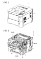
- FIG. 1 is a perspective view of a printer 1 (image forming apparatus) of the present embodiment.
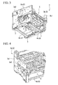
- FIG. 2 is a perspective view of the printer 1 of the present embodiment in which a face panel is omitted.
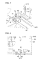
- FIG. 3 is a perspective view viewed from below, with devices installed at side plate panels being further omitted from FIG. 2 .
- the direction in the following descriptions is a direction when the printer 1 is viewed from the front face.
- the printer 1 of the present embodiment is covered with a face panel 2.
- side plate frames 3 (a left side plate frame (a first metal side plate frame) 3a and a right side plate frame (a second metal side plate frame) 3b) that are strength members, a sheet-metal stay 4 that connects the side plate frames 3, an image forming section 5 that forms an image on recording paper, other required devices (fan 6 or the like that cools the inside of the printer 1), and a rubber mount 7 are included inside the printer.
- the side plate frames 3 are metallic plate-shaped strength members. As shown in FIG. 3 , in the printer 1 of the present embodiment, a left side plate frame 3a arranged on the left side of the printer 1 and a right side plate frame 3b arranged on the right side are installed as the side plate frames 3. The left side plate frame 3a and the right side plate frame 3b are arranged in parallel such that their in-plane sides are made to face each other.
- FIG. 4 is a perspective view when the left side of a printer 1 is seen from above in FIG. 3 .
- a flange portion 3a1 is provided at the edge of the left side plate frame 3a except for a portion on the lower side.
- the flange portion 3a1 is erected outward from an outer surface 3a2 of the left side plate frame 3a.
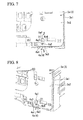
- FIG. 5 is an enlarged perspective view of a connection portion between the left side plate frame 3a and the sheet-metal stay 4.
- FIG. 6 is an enlarged side view of the connection portion between the left side plate frame 3a and the sheet-metal stay 4.
- the flange portion 3a1 of the left side plate frame 3a is provided with a through hole 3a3 that allows a portion of the sheet-metal stay 4 (fastening portion 4a2 to be described below) to pass therethrough.
- connection portion between a near-side sheet-metal stay 4a of the two sheet-metal stays 4 arranged on the near side and the left side plate frame 3a is shown in an enlarged manner in FIG. 5 .
- a connection portion between a back-side sheet-metal stay 4b arranged on the back side and the left side plate frame 3a is also the same as that of the structure shown in FIG. 5 .
- a through hole that allows a portion (fastening portion) of the back-side sheet-metal stay 4b to pass therethrough is also provided in a connection portion with the back-side sheet-metal stay 4b, in a flange portion 3b1 of the left side plate frame 3a.
- the right side plate frame 3b has almost the same shape as the left side plate frame 3a, although the arrangement of attachment holes or the like is different due to differences in the devices to be attached.
- the flange portion 3b1 having a through hole through which a portion (fastening portion) of the sheet-metal stay 4 passes has a shape that is provided at the edge except for a portion on the lower side. Since the right side plate frame 3b has almost the same shape as the left side plate frame 3a in this way, the enlarged illustration is omitted.
- the sheet-metal stay 4 is arranged at the bottom of the printer 1, and is a metallic long-plate-shaped member that is long in the direction separating the side plate frames 3.
- the sheet-metal stay 4 has a left end connected to the left side plate frame 3a and a right end connected to the right side plate frame 3b.
- the near-side sheet-metal stay 4a arranged on the near side of the printer 1 and the back-side sheet-metal stay 4b arranged on the back side are installed as the sheet-metal stays 4.
- the near-side stay 4a includes a base portion 4a1 that extends horizontally and a fastening portion 4a2 that rises from the base portion 4a1.
- the base portion 4a1 extends from the left side plate frame 3a to the right side plate frame 3b, and is fastened to a resin member 5a provided in the image forming section 5 with screws 10.
- the fastening portion 4a2 is provided at a left end of the near-side stay 4a, and is set to a width capable of being inserted into the through hole 3a3 provided in the flange portion 3a1.
- FIG. 7 is a side view in which a screw 20 (fastening member) that fastens the fastening portion 4a2 and the left side plate frame 3a is omitted.
- FIG. 8 is a perspective view in which the screw 20 that fastens the fastening portion 4a2 and the left side plate frame 3a is omitted.
- the height of the fastening portion 4a2 is set so that the position of an upper end 4a3 becomes the fastening position of the screw 20.
- the fastening portion 4a2 has a U-shaped recess 4a4 that is formed by a central portion of the upper end 4a3 being recessed downward.
- the recess 4a4 is provided to position the shank of the screw 20, and is also used to position the near-side stay 4a and the left side plate frame 3a by being aligned with a screw hole 21 provided in the left side plate frame 3a during assembly.
- Such a fastening portion 4a2 is fastened to the left side plate frame 3a by the screw 20 (fastening member).
- the fastening portion 4a2 abuts against the outer surface 3a2 of the left side plate frame 3a.
- fastening portions are provided also at a right end of the near-side sheet-metal stay 4a and at left and right ends of the back-side sheet-metal stay 4b. These fastening portions also have the same shape as the above fastening portion 4a2. Since the fastening structure between these fastening portions and the side plate frames 3 is the same as the fastening structure of the fastening portion 4a2 and the left side plate frame 3a, illustration is omitted.
- the fastening portion provided at the right end of the near-side stay 4a is fastened to the right side plate frame 3b by a screw (fastening member), and abuts the outer surface of the right side plate frame 3b.
- the fastening portion provided at the left end of the back-side stay 4b is fastened to the left side plate frame 3b by a screw (fastening member), and abuts the outer surface 3a2 of the left side plate frame 3a. Additionally, the fastening portion provided at the right end of the back-side stay 4b is fastened to the right side plate frame 3b by a screw, and abuts the outer surface of the right side plate frame 3b.
- left side plate frame 3a and the right side plate frame 3b are electrically connected by the near-side sheet-metal stay 4a and the back-side sheet-metal stay 4b being connected to the left side plate frame 3a and the right side plate frame 3b as described above.
- the side plate frames 3 are electrically connected by the sheet-metal stays 4.
- the right side plate frame 3b is directly grounded to an inlet that is not shown. For this reason, the left side plate frame 3a electrically connected to the right side plate frame 3b by the sheet-metal stays 4 is also indirectly grounded.
- the image forming section 5 which is a principal section of the printer 1, forms an image on recording paper.
- the image forming section 5 includes a photoreceptor drum, a laser scanning unit, a developing unit, a toner container, a fixing device, and the like, and includes a number of resin members, such as a resin case.
- the resin member 5a shown in FIG. 5 also constitutes a portion of such an image forming section 5.
- FIG. 9 is a cross-sectional perspective view taken along line A-A of FIG. 7 .
- the resin member 5 a includes a cylindrical projection 5a1 that protrudes toward the left side plate frame 3a.
- the projection 5a1 is inserted into a positioning hole 3a4 provided immediately above the fastening portion 4a2.
- the left side plate frame 3a and the resin member 5a are positioned by inserting the projection 5a1 of the resin member 5a into the positioning hole 3a4 of the left side plate frame 3a in this way. Then, the resin member 5a and the left side plate frame 3a are fastened by a screw (not shown) from the outer surface 3a2 side.
- the positioning structure (the projection 5a1 and the positioning hole 3a4) between the resin member 5a (image forming section 5) and the left side plate frame 3a is arranged immediately above the screw 20.
- positioning mechanisms that position the resin members (image forming section 5) and the side plate frames 3 are arranged immediately above some screws that fasten all the fastening portions and side plate frames 3, and are not limited to only immediately above the screw 20 that fastens the fastening portion 4a2 and the left side plate frame 3a.
- these positioning mechanisms have the same structure as the above-described positioning mechanism including the projection 5a1 and positioning holes 3a4, illustration is omitted.
- devices such as a fan 6 for cooling the image forming section 5 and recording paper are fixed to the side plate frame 3.
- connectors for connecting cables, a control board that controls the printer 1, and the like are installed at the side plate frames 3.
- Rubber mounts 7 (legs) are arranged at the bottom of the printer 1.
- the face panel 2 is not provided on the bottom face of the printer 1, and the sheet-metal stays 4 are exposed.
- the rubber mounts 7 are fixed to the exposed sheet-metal stays 4 via adhesive.
- the rubber mounts 7 are installed at four corners of the bottom face of the printer 1. In a case where the printer 1 is installed on an installation surface, these rubber mounts 7 directly abut the installation surface and support the printer 1.
- the rubber mount 7, the screw (screw 20), and the positioning mechanism (the projection 5a1 and the positioning holes 3a4) are arrayed linearly in the vertical direction (for example, refer to FIG. 5 ).
- the screw (screw 20, fastening member) and the positioning mechanism (the projection 5a1 and the positioning hole 3a4) are arranged immediately above the rubber mount supporting the printer 1.
- the sheet-metal stay 4 includes the base portion 4a1 (the same is also true in the other base portions) that extends horizontally, and the fastening portion 4a2 (the same is also true hereinbelow in the other fastening portions) that rises from the base portion 4a1. Additionally, the fastening portion 4a2 abuts the outer surface 3a2 of the side plate frame 3. For this reason, even in a case where the height of the flange portion 3a1 (the same is also true in the flange portion 3b1) provided at the edge of the side plate frame 3 is low as in the present embodiment, it is possible to reliably bring the fastening portion 4a2 into contact with the side plate frame 3.
- the printer 1 of the present embodiment it is possible to electrically connect the sheet-metal stay 4 and the side plate frame 3 reliably.
- the flange portion 3a1 flange portion 3b1
- the side plate frame 3 can be reliably electrically grounded as well as the size of apparatus size is reduced.
- the fastening portion 4a2 and the side plate frame 3 are fastened by the screw 20 (the same is also true in the other screws). For this reason, the contact between the fastening portion 4a2 and the side plate frame 3 can be made more reliable, and the side plate frame 3 can be more reliably electrically grounded.
- the fastening portion 4a2 abuts the outer surface of the side plate frame 3. For this reason, during assembly, screwing work can be performed from the outside of the side plate frame 3 and completion of the screwing stop work can be viewed from the outside of the side plate frame 3. Accordingly, according to the printer 1 of the present embodiment, the workability during assembly is improved.
- the upper end 4a3 of the fastening portion 4a2 is set at the fastening position of the screw 20, and the recess 4a4 where the screw 20 is positioned is provided at the upper end of the fastening portion 4a2.
- a screw hole is provided at a fastening portion and the screw 20 is positioned in this screw hole.
- the height of the fastening portion becomes higher than the fastening portion 4a2 of the present embodiment, and the material required for forming the fastening portion increases.
- the fastening portion 4a2 with a low height is adopted, so that the sheet-metal stay 4 can be formed from little material.
- the positioning structure (the projection 5a1 and the positioning hole 3a4) between the resin member 5a arranged between the side plate frames and the side plate frame 3, the rubber mount 7 that abuts the installation surface, and the screw 20 are arranged in the vertical direction. For this reason, a load that enters from the rubber mount 7 enters the resin member 5a in the vertical direction, so that deformation of the resin member 5a can be prevented.
- An abutting portion that reliably abuts the outer surface of the side plate frame 3 even if screwing is not performed may be used instead of the fastening portion 4a2.
- This abutting portion is also formed so as to rise from the base portion 4a1 of the sheet-metal stay 4, similarly to the fastening portion 4a2.
- the structure for ensuring the abutment between the abutting portion and the side plate frame 3 it is preferable to adopt the structure for ensuring the abutment between the abutting portion and the side plate frame 3.
- the structure in which the abutting portion is slightly inclined or curved to the side plate frame 3 side is adopted.
- the abutting portion is pushed outward by the side plate frame 3 and the abutting portion is brought into pressure contact with to the side plate frame 3 due to the restoring force of the abutting portion generated by this.
- electrical connection can be secured by causing the abutting portion and the side plate frame 3 to reliably abut each other.
- the recess may have other shapes, such as the V-shape.
- this disclosure is not limited thereto, and, for example, it is also possible to provide a constricted portion at the sheet-metal stay 4 and use the constricted portion as the leg.
- this disclosure not to be limited to this, and this disclosure may also be applied to image forming apparatuses, such as a copying machine, a facsimile, or a composite machine including a plurality of functions.
Landscapes
- Physics & Mathematics (AREA)
- General Physics & Mathematics (AREA)
- Electrophotography Configuration And Component (AREA)
Applications Claiming Priority (1)
| Application Number | Priority Date | Filing Date | Title |
|---|---|---|---|
| JP2011253793A JP5450571B2 (ja) | 2011-11-21 | 2011-11-21 | 画像形成装置 |
Publications (3)
| Publication Number | Publication Date |
|---|---|
| EP2595003A2 true EP2595003A2 (de) | 2013-05-22 |
| EP2595003A3 EP2595003A3 (de) | 2015-03-11 |
| EP2595003B1 EP2595003B1 (de) | 2019-05-01 |
Family
ID=47278661
Family Applications (1)
| Application Number | Title | Priority Date | Filing Date |
|---|---|---|---|
| EP12193136.4A Active EP2595003B1 (de) | 2011-11-21 | 2012-11-19 | Bilderzeugungsvorrichtung |
Country Status (5)
| Country | Link |
|---|---|
| US (1) | US8897669B2 (de) |
| EP (1) | EP2595003B1 (de) |
| JP (1) | JP5450571B2 (de) |
| KR (1) | KR101377814B1 (de) |
| CN (1) | CN103135387B (de) |
Families Citing this family (3)
| Publication number | Priority date | Publication date | Assignee | Title |
|---|---|---|---|---|
| JP6295728B2 (ja) * | 2014-03-03 | 2018-03-20 | 富士ゼロックス株式会社 | 枠体構造、装置枠体、および画像形成装置 |
| JP6463134B2 (ja) | 2015-01-06 | 2019-01-30 | キヤノン株式会社 | 画像形成装置の構造体、画像形成装置及び画像形成装置の構造体の製造方法 |
| JP7191664B2 (ja) | 2018-12-04 | 2022-12-19 | キヤノン株式会社 | 画像形成装置 |
Family Cites Families (18)
| Publication number | Priority date | Publication date | Assignee | Title |
|---|---|---|---|---|
| JPS6265051A (ja) * | 1985-09-18 | 1987-03-24 | Sanyo Electric Co Ltd | 複写機のフレ−ム |
| JPH01172977A (ja) * | 1987-12-28 | 1989-07-07 | Toshiba Corp | 画像形成装置 |
| JPH053612A (ja) | 1990-11-13 | 1993-01-08 | Toshiba Corp | ガス絶縁開閉装置 |
| JP2500731Y2 (ja) * | 1991-03-05 | 1996-06-12 | 日通工株式会社 | フレ―ム開口部へのカバ―取付構造 |
| JPH053612U (ja) * | 1991-06-28 | 1993-01-19 | アンリツ株式会社 | パネルの取付け構造 |
| JP2004122444A (ja) * | 2002-09-30 | 2004-04-22 | Canon Inc | 画像形成装置の枠体 |
| JP4241013B2 (ja) * | 2002-11-26 | 2009-03-18 | 富士ゼロックス株式会社 | 画像形成装置並びにこれに用いられるフレーム構造及びその製造方法 |
| JP2004301897A (ja) * | 2003-03-28 | 2004-10-28 | Canon Inc | 画像形成装置 |
| JP4383807B2 (ja) * | 2003-08-29 | 2009-12-16 | キヤノン株式会社 | 画像形成装置 |
| JP2006178159A (ja) | 2004-12-22 | 2006-07-06 | Kyocera Mita Corp | 画像形成装置のフレーム構造及びフレーム組み付け方法 |
| JP4708037B2 (ja) | 2005-01-26 | 2011-06-22 | 京セラミタ株式会社 | 画像形成装置用筐体 |
| JP4084361B2 (ja) * | 2005-01-31 | 2008-04-30 | 株式会社リコー | 画像形成装置 |
| JP4632425B2 (ja) * | 2005-02-03 | 2011-02-16 | 株式会社リコー | 筐体構造、これを備えた装置、及び画像形成装置 |
| JP4713317B2 (ja) * | 2005-11-25 | 2011-06-29 | 株式会社リコー | 外装天板の取り付け方法、取り付け構造、画像形成装置、周辺装置及び画像形成システム |
| JP2008009260A (ja) | 2006-06-30 | 2008-01-17 | Brother Ind Ltd | 画像形成装置 |
| JP2009025722A (ja) * | 2007-07-23 | 2009-02-05 | Canon Inc | 画像形成装置 |
| JP2010200313A (ja) * | 2009-01-28 | 2010-09-09 | Kyocera Mita Corp | 筐体構造及びそれを備えた画像読取装置 |
| JP2010201801A (ja) * | 2009-03-04 | 2010-09-16 | Ricoh Co Ltd | フレーム構造、及び、画像形成装置 |
-
2011
- 2011-11-21 JP JP2011253793A patent/JP5450571B2/ja active Active
-
2012
- 2012-11-14 US US13/676,240 patent/US8897669B2/en active Active
- 2012-11-16 KR KR1020120130124A patent/KR101377814B1/ko active Active
- 2012-11-16 CN CN201210465099.3A patent/CN103135387B/zh active Active
- 2012-11-19 EP EP12193136.4A patent/EP2595003B1/de active Active
Non-Patent Citations (1)
| Title |
|---|
| None |
Also Published As
| Publication number | Publication date |
|---|---|
| KR20130056181A (ko) | 2013-05-29 |
| CN103135387B (zh) | 2015-09-23 |
| KR101377814B1 (ko) | 2014-03-25 |
| CN103135387A (zh) | 2013-06-05 |
| EP2595003B1 (de) | 2019-05-01 |
| US20130129380A1 (en) | 2013-05-23 |
| JP2013109141A (ja) | 2013-06-06 |
| US8897669B2 (en) | 2014-11-25 |
| JP5450571B2 (ja) | 2014-03-26 |
| EP2595003A3 (de) | 2015-03-11 |
Similar Documents
| Publication | Publication Date | Title |
|---|---|---|
| US10304606B2 (en) | Coil assembly, structure for attaching coil assembly, and electrical connection box | |
| CN100470610C (zh) | 显示设备 | |
| US8213186B2 (en) | Retaining assembly and apparatus using the same | |
| US7667782B2 (en) | Liquid crystal display device capable of restraining deformation of a cabinet by heat | |
| KR20100136804A (ko) | 보드연결 브라켓 및 그를 구비한 전자기기 | |
| CN106896659A (zh) | 图像形成装置 | |
| JP2023041689A (ja) | 電子基板取付けシステム | |
| US8897669B2 (en) | Image forming apparatus | |
| US9101045B2 (en) | Shield structure for electronic apparatus | |
| JP6414030B2 (ja) | 画像形成装置 | |
| JP2004151510A (ja) | 画像形成装置用フレーム | |
| CN103493505B (zh) | 子机架安装支架和组件 | |
| CN107872939B (zh) | 用于机架的滑轨安装配件总成 | |
| US20120038252A1 (en) | Mounting apparatus for power supply | |
| JP2012053082A (ja) | 画像表示装置 | |
| EP2651203A2 (de) | Stromversorgungsmodul | |
| JP5085772B1 (ja) | 壁掛け具、および表示装置 | |
| JP2005352305A (ja) | フラットディスプレイ装置及びその製造方法 | |
| US20260040473A1 (en) | Fixing member and electronic device | |
| JPH10239932A (ja) | 電子写真装置のモジュール連結構造 | |
| EP2367411A2 (de) | Anzeigevorrichtung und elektronische Vorrichtung | |
| KR100856461B1 (ko) | 화상출력장치용 프레임 및 이를 구비하는 화상출력장치 | |
| US20130169123A1 (en) | Enclosure assembly | |
| JP4837138B2 (ja) | 表示装置及び電子機器 | |
| JP5812902B2 (ja) | 表示装置 |
Legal Events
| Date | Code | Title | Description |
|---|---|---|---|
| PUAI | Public reference made under article 153(3) epc to a published international application that has entered the european phase |
Free format text: ORIGINAL CODE: 0009012 |
|
| AK | Designated contracting states |
Kind code of ref document: A2 Designated state(s): AL AT BE BG CH CY CZ DE DK EE ES FI FR GB GR HR HU IE IS IT LI LT LU LV MC MK MT NL NO PL PT RO RS SE SI SK SM TR |
|
| AX | Request for extension of the european patent |
Extension state: BA ME |
|
| PUAL | Search report despatched |
Free format text: ORIGINAL CODE: 0009013 |
|
| AK | Designated contracting states |
Kind code of ref document: A3 Designated state(s): AL AT BE BG CH CY CZ DE DK EE ES FI FR GB GR HR HU IE IS IT LI LT LU LV MC MK MT NL NO PL PT RO RS SE SI SK SM TR |
|
| AX | Request for extension of the european patent |
Extension state: BA ME |
|
| RIC1 | Information provided on ipc code assigned before grant |
Ipc: G03G 21/16 20060101AFI20150204BHEP |
|
| 17P | Request for examination filed |
Effective date: 20150910 |
|
| RBV | Designated contracting states (corrected) |
Designated state(s): AL AT BE BG CH CY CZ DE DK EE ES FI FR GB GR HR HU IE IS IT LI LT LU LV MC MK MT NL NO PL PT RO RS SE SI SK SM TR |
|
| GRAP | Despatch of communication of intention to grant a patent |
Free format text: ORIGINAL CODE: EPIDOSNIGR1 |
|
| STAA | Information on the status of an ep patent application or granted ep patent |
Free format text: STATUS: GRANT OF PATENT IS INTENDED |
|
| INTG | Intention to grant announced |
Effective date: 20181122 |
|
| GRAS | Grant fee paid |
Free format text: ORIGINAL CODE: EPIDOSNIGR3 |
|
| GRAA | (expected) grant |
Free format text: ORIGINAL CODE: 0009210 |
|
| STAA | Information on the status of an ep patent application or granted ep patent |
Free format text: STATUS: THE PATENT HAS BEEN GRANTED |
|
| AK | Designated contracting states |
Kind code of ref document: B1 Designated state(s): AL AT BE BG CH CY CZ DE DK EE ES FI FR GB GR HR HU IE IS IT LI LT LU LV MC MK MT NL NO PL PT RO RS SE SI SK SM TR |
|
| REG | Reference to a national code |
Ref country code: GB Ref legal event code: FG4D |
|
| REG | Reference to a national code |
Ref country code: CH Ref legal event code: EP Ref country code: AT Ref legal event code: REF Ref document number: 1127748 Country of ref document: AT Kind code of ref document: T Effective date: 20190515 |
|
| REG | Reference to a national code |
Ref country code: DE Ref legal event code: R096 Ref document number: 602012059541 Country of ref document: DE |
|
| REG | Reference to a national code |
Ref country code: IE Ref legal event code: FG4D |
|
| REG | Reference to a national code |
Ref country code: NL Ref legal event code: MP Effective date: 20190501 |
|
| REG | Reference to a national code |
Ref country code: LT Ref legal event code: MG4D |
|
| PG25 | Lapsed in a contracting state [announced via postgrant information from national office to epo] |
Ref country code: AL Free format text: LAPSE BECAUSE OF FAILURE TO SUBMIT A TRANSLATION OF THE DESCRIPTION OR TO PAY THE FEE WITHIN THE PRESCRIBED TIME-LIMIT Effective date: 20190501 Ref country code: ES Free format text: LAPSE BECAUSE OF FAILURE TO SUBMIT A TRANSLATION OF THE DESCRIPTION OR TO PAY THE FEE WITHIN THE PRESCRIBED TIME-LIMIT Effective date: 20190501 Ref country code: NL Free format text: LAPSE BECAUSE OF FAILURE TO SUBMIT A TRANSLATION OF THE DESCRIPTION OR TO PAY THE FEE WITHIN THE PRESCRIBED TIME-LIMIT Effective date: 20190501 Ref country code: LT Free format text: LAPSE BECAUSE OF FAILURE TO SUBMIT A TRANSLATION OF THE DESCRIPTION OR TO PAY THE FEE WITHIN THE PRESCRIBED TIME-LIMIT Effective date: 20190501 Ref country code: FI Free format text: LAPSE BECAUSE OF FAILURE TO SUBMIT A TRANSLATION OF THE DESCRIPTION OR TO PAY THE FEE WITHIN THE PRESCRIBED TIME-LIMIT Effective date: 20190501 Ref country code: HR Free format text: LAPSE BECAUSE OF FAILURE TO SUBMIT A TRANSLATION OF THE DESCRIPTION OR TO PAY THE FEE WITHIN THE PRESCRIBED TIME-LIMIT Effective date: 20190501 Ref country code: SE Free format text: LAPSE BECAUSE OF FAILURE TO SUBMIT A TRANSLATION OF THE DESCRIPTION OR TO PAY THE FEE WITHIN THE PRESCRIBED TIME-LIMIT Effective date: 20190501 Ref country code: NO Free format text: LAPSE BECAUSE OF FAILURE TO SUBMIT A TRANSLATION OF THE DESCRIPTION OR TO PAY THE FEE WITHIN THE PRESCRIBED TIME-LIMIT Effective date: 20190801 Ref country code: PT Free format text: LAPSE BECAUSE OF FAILURE TO SUBMIT A TRANSLATION OF THE DESCRIPTION OR TO PAY THE FEE WITHIN THE PRESCRIBED TIME-LIMIT Effective date: 20190901 |
|
| PG25 | Lapsed in a contracting state [announced via postgrant information from national office to epo] |
Ref country code: RS Free format text: LAPSE BECAUSE OF FAILURE TO SUBMIT A TRANSLATION OF THE DESCRIPTION OR TO PAY THE FEE WITHIN THE PRESCRIBED TIME-LIMIT Effective date: 20190501 Ref country code: LV Free format text: LAPSE BECAUSE OF FAILURE TO SUBMIT A TRANSLATION OF THE DESCRIPTION OR TO PAY THE FEE WITHIN THE PRESCRIBED TIME-LIMIT Effective date: 20190501 Ref country code: GR Free format text: LAPSE BECAUSE OF FAILURE TO SUBMIT A TRANSLATION OF THE DESCRIPTION OR TO PAY THE FEE WITHIN THE PRESCRIBED TIME-LIMIT Effective date: 20190802 Ref country code: BG Free format text: LAPSE BECAUSE OF FAILURE TO SUBMIT A TRANSLATION OF THE DESCRIPTION OR TO PAY THE FEE WITHIN THE PRESCRIBED TIME-LIMIT Effective date: 20190801 |
|
| REG | Reference to a national code |
Ref country code: AT Ref legal event code: MK05 Ref document number: 1127748 Country of ref document: AT Kind code of ref document: T Effective date: 20190501 |
|
| PG25 | Lapsed in a contracting state [announced via postgrant information from national office to epo] |
Ref country code: IS Free format text: LAPSE BECAUSE OF FAILURE TO SUBMIT A TRANSLATION OF THE DESCRIPTION OR TO PAY THE FEE WITHIN THE PRESCRIBED TIME-LIMIT Effective date: 20190901 |
|
| PG25 | Lapsed in a contracting state [announced via postgrant information from national office to epo] |
Ref country code: CZ Free format text: LAPSE BECAUSE OF FAILURE TO SUBMIT A TRANSLATION OF THE DESCRIPTION OR TO PAY THE FEE WITHIN THE PRESCRIBED TIME-LIMIT Effective date: 20190501 Ref country code: RO Free format text: LAPSE BECAUSE OF FAILURE TO SUBMIT A TRANSLATION OF THE DESCRIPTION OR TO PAY THE FEE WITHIN THE PRESCRIBED TIME-LIMIT Effective date: 20190501 Ref country code: SK Free format text: LAPSE BECAUSE OF FAILURE TO SUBMIT A TRANSLATION OF THE DESCRIPTION OR TO PAY THE FEE WITHIN THE PRESCRIBED TIME-LIMIT Effective date: 20190501 Ref country code: EE Free format text: LAPSE BECAUSE OF FAILURE TO SUBMIT A TRANSLATION OF THE DESCRIPTION OR TO PAY THE FEE WITHIN THE PRESCRIBED TIME-LIMIT Effective date: 20190501 Ref country code: DK Free format text: LAPSE BECAUSE OF FAILURE TO SUBMIT A TRANSLATION OF THE DESCRIPTION OR TO PAY THE FEE WITHIN THE PRESCRIBED TIME-LIMIT Effective date: 20190501 Ref country code: AT Free format text: LAPSE BECAUSE OF FAILURE TO SUBMIT A TRANSLATION OF THE DESCRIPTION OR TO PAY THE FEE WITHIN THE PRESCRIBED TIME-LIMIT Effective date: 20190501 |
|
| REG | Reference to a national code |
Ref country code: DE Ref legal event code: R097 Ref document number: 602012059541 Country of ref document: DE |
|
| PG25 | Lapsed in a contracting state [announced via postgrant information from national office to epo] |
Ref country code: SM Free format text: LAPSE BECAUSE OF FAILURE TO SUBMIT A TRANSLATION OF THE DESCRIPTION OR TO PAY THE FEE WITHIN THE PRESCRIBED TIME-LIMIT Effective date: 20190501 Ref country code: IT Free format text: LAPSE BECAUSE OF FAILURE TO SUBMIT A TRANSLATION OF THE DESCRIPTION OR TO PAY THE FEE WITHIN THE PRESCRIBED TIME-LIMIT Effective date: 20190501 |
|
| PLBE | No opposition filed within time limit |
Free format text: ORIGINAL CODE: 0009261 |
|
| STAA | Information on the status of an ep patent application or granted ep patent |
Free format text: STATUS: NO OPPOSITION FILED WITHIN TIME LIMIT |
|
| PG25 | Lapsed in a contracting state [announced via postgrant information from national office to epo] |
Ref country code: TR Free format text: LAPSE BECAUSE OF FAILURE TO SUBMIT A TRANSLATION OF THE DESCRIPTION OR TO PAY THE FEE WITHIN THE PRESCRIBED TIME-LIMIT Effective date: 20190501 |
|
| 26N | No opposition filed |
Effective date: 20200204 |
|
| PG25 | Lapsed in a contracting state [announced via postgrant information from national office to epo] |
Ref country code: PL Free format text: LAPSE BECAUSE OF FAILURE TO SUBMIT A TRANSLATION OF THE DESCRIPTION OR TO PAY THE FEE WITHIN THE PRESCRIBED TIME-LIMIT Effective date: 20190501 |
|
| PG25 | Lapsed in a contracting state [announced via postgrant information from national office to epo] |
Ref country code: SI Free format text: LAPSE BECAUSE OF FAILURE TO SUBMIT A TRANSLATION OF THE DESCRIPTION OR TO PAY THE FEE WITHIN THE PRESCRIBED TIME-LIMIT Effective date: 20190501 |
|
| REG | Reference to a national code |
Ref country code: CH Ref legal event code: PL |
|
| PG25 | Lapsed in a contracting state [announced via postgrant information from national office to epo] |
Ref country code: LI Free format text: LAPSE BECAUSE OF NON-PAYMENT OF DUE FEES Effective date: 20191130 Ref country code: CH Free format text: LAPSE BECAUSE OF NON-PAYMENT OF DUE FEES Effective date: 20191130 Ref country code: MC Free format text: LAPSE BECAUSE OF FAILURE TO SUBMIT A TRANSLATION OF THE DESCRIPTION OR TO PAY THE FEE WITHIN THE PRESCRIBED TIME-LIMIT Effective date: 20190501 Ref country code: LU Free format text: LAPSE BECAUSE OF NON-PAYMENT OF DUE FEES Effective date: 20191119 |
|
| REG | Reference to a national code |
Ref country code: BE Ref legal event code: MM Effective date: 20191130 |
|
| PG25 | Lapsed in a contracting state [announced via postgrant information from national office to epo] |
Ref country code: FR Free format text: LAPSE BECAUSE OF NON-PAYMENT OF DUE FEES Effective date: 20191130 Ref country code: IE Free format text: LAPSE BECAUSE OF NON-PAYMENT OF DUE FEES Effective date: 20191119 |
|
| PG25 | Lapsed in a contracting state [announced via postgrant information from national office to epo] |
Ref country code: BE Free format text: LAPSE BECAUSE OF NON-PAYMENT OF DUE FEES Effective date: 20191130 |
|
| PG25 | Lapsed in a contracting state [announced via postgrant information from national office to epo] |
Ref country code: CY Free format text: LAPSE BECAUSE OF FAILURE TO SUBMIT A TRANSLATION OF THE DESCRIPTION OR TO PAY THE FEE WITHIN THE PRESCRIBED TIME-LIMIT Effective date: 20190501 |
|
| PG25 | Lapsed in a contracting state [announced via postgrant information from national office to epo] |
Ref country code: MT Free format text: LAPSE BECAUSE OF FAILURE TO SUBMIT A TRANSLATION OF THE DESCRIPTION OR TO PAY THE FEE WITHIN THE PRESCRIBED TIME-LIMIT Effective date: 20190501 Ref country code: HU Free format text: LAPSE BECAUSE OF FAILURE TO SUBMIT A TRANSLATION OF THE DESCRIPTION OR TO PAY THE FEE WITHIN THE PRESCRIBED TIME-LIMIT; INVALID AB INITIO Effective date: 20121119 |
|
| PG25 | Lapsed in a contracting state [announced via postgrant information from national office to epo] |
Ref country code: MK Free format text: LAPSE BECAUSE OF FAILURE TO SUBMIT A TRANSLATION OF THE DESCRIPTION OR TO PAY THE FEE WITHIN THE PRESCRIBED TIME-LIMIT Effective date: 20190501 |
|
| P01 | Opt-out of the competence of the unified patent court (upc) registered |
Effective date: 20230420 |
|
| PGFP | Annual fee paid to national office [announced via postgrant information from national office to epo] |
Ref country code: DE Payment date: 20251022 Year of fee payment: 14 |
|
| PGFP | Annual fee paid to national office [announced via postgrant information from national office to epo] |
Ref country code: GB Payment date: 20251022 Year of fee payment: 14 |