EP2594979B1 - Detection optical system and scanning microscope - Google Patents
Detection optical system and scanning microscope Download PDFInfo
- Publication number
- EP2594979B1 EP2594979B1 EP12007625.2A EP12007625A EP2594979B1 EP 2594979 B1 EP2594979 B1 EP 2594979B1 EP 12007625 A EP12007625 A EP 12007625A EP 2594979 B1 EP2594979 B1 EP 2594979B1
- Authority
- EP
- European Patent Office
- Prior art keywords
- light
- diffraction grating
- specimen
- angle
- vph diffraction
- Prior art date
- Legal status (The legal status is an assumption and is not a legal conclusion. Google has not performed a legal analysis and makes no representation as to the accuracy of the status listed.)
- Not-in-force
Links
Images


Classifications
-
- G—PHYSICS
- G02—OPTICS
- G02B—OPTICAL ELEMENTS, SYSTEMS OR APPARATUS
- G02B21/00—Microscopes
- G02B21/0004—Microscopes specially adapted for specific applications
- G02B21/002—Scanning microscopes
- G02B21/0024—Confocal scanning microscopes (CSOMs) or confocal "macroscopes"; Accessories which are not restricted to use with CSOMs, e.g. sample holders
- G02B21/0052—Optical details of the image generation
- G02B21/0076—Optical details of the image generation arrangements using fluorescence or luminescence
-
- G—PHYSICS
- G01—MEASURING; TESTING
- G01J—MEASUREMENT OF INTENSITY, VELOCITY, SPECTRAL CONTENT, POLARISATION, PHASE OR PULSE CHARACTERISTICS OF INFRARED, VISIBLE OR ULTRAVIOLET LIGHT; COLORIMETRY; RADIATION PYROMETRY
- G01J3/00—Spectrometry; Spectrophotometry; Monochromators; Measuring colours
- G01J3/02—Details
- G01J3/0205—Optical elements not provided otherwise, e.g. optical manifolds, diffusers, windows
- G01J3/0208—Optical elements not provided otherwise, e.g. optical manifolds, diffusers, windows using focussing or collimating elements, e.g. lenses or mirrors; performing aberration correction
-
- G—PHYSICS
- G01—MEASURING; TESTING
- G01J—MEASUREMENT OF INTENSITY, VELOCITY, SPECTRAL CONTENT, POLARISATION, PHASE OR PULSE CHARACTERISTICS OF INFRARED, VISIBLE OR ULTRAVIOLET LIGHT; COLORIMETRY; RADIATION PYROMETRY
- G01J3/00—Spectrometry; Spectrophotometry; Monochromators; Measuring colours
- G01J3/02—Details
- G01J3/0205—Optical elements not provided otherwise, e.g. optical manifolds, diffusers, windows
- G01J3/021—Optical elements not provided otherwise, e.g. optical manifolds, diffusers, windows using plane or convex mirrors, parallel phase plates, or particular reflectors
-
- G—PHYSICS
- G01—MEASURING; TESTING
- G01J—MEASUREMENT OF INTENSITY, VELOCITY, SPECTRAL CONTENT, POLARISATION, PHASE OR PULSE CHARACTERISTICS OF INFRARED, VISIBLE OR ULTRAVIOLET LIGHT; COLORIMETRY; RADIATION PYROMETRY
- G01J3/00—Spectrometry; Spectrophotometry; Monochromators; Measuring colours
- G01J3/02—Details
- G01J3/0205—Optical elements not provided otherwise, e.g. optical manifolds, diffusers, windows
- G01J3/0237—Adjustable, e.g. focussing
-
- G—PHYSICS
- G01—MEASURING; TESTING
- G01J—MEASUREMENT OF INTENSITY, VELOCITY, SPECTRAL CONTENT, POLARISATION, PHASE OR PULSE CHARACTERISTICS OF INFRARED, VISIBLE OR ULTRAVIOLET LIGHT; COLORIMETRY; RADIATION PYROMETRY
- G01J3/00—Spectrometry; Spectrophotometry; Monochromators; Measuring colours
- G01J3/02—Details
- G01J3/06—Scanning arrangements arrangements for order-selection
-
- G—PHYSICS
- G01—MEASURING; TESTING
- G01J—MEASUREMENT OF INTENSITY, VELOCITY, SPECTRAL CONTENT, POLARISATION, PHASE OR PULSE CHARACTERISTICS OF INFRARED, VISIBLE OR ULTRAVIOLET LIGHT; COLORIMETRY; RADIATION PYROMETRY
- G01J3/00—Spectrometry; Spectrophotometry; Monochromators; Measuring colours
- G01J3/12—Generating the spectrum; Monochromators
- G01J3/18—Generating the spectrum; Monochromators using diffraction elements, e.g. grating
- G01J3/1838—Holographic gratings
-
- G—PHYSICS
- G01—MEASURING; TESTING
- G01J—MEASUREMENT OF INTENSITY, VELOCITY, SPECTRAL CONTENT, POLARISATION, PHASE OR PULSE CHARACTERISTICS OF INFRARED, VISIBLE OR ULTRAVIOLET LIGHT; COLORIMETRY; RADIATION PYROMETRY
- G01J3/00—Spectrometry; Spectrophotometry; Monochromators; Measuring colours
- G01J3/28—Investigating the spectrum
- G01J3/44—Raman spectrometry; Scattering spectrometry ; Fluorescence spectrometry
- G01J3/4406—Fluorescence spectrometry
-
- G—PHYSICS
- G02—OPTICS
- G02B—OPTICAL ELEMENTS, SYSTEMS OR APPARATUS
- G02B21/00—Microscopes
- G02B21/0004—Microscopes specially adapted for specific applications
- G02B21/002—Scanning microscopes
- G02B21/0024—Confocal scanning microscopes (CSOMs) or confocal "macroscopes"; Accessories which are not restricted to use with CSOMs, e.g. sample holders
- G02B21/0052—Optical details of the image generation
- G02B21/0064—Optical details of the image generation multi-spectral or wavelength-selective arrangements, e.g. wavelength fan-out, chromatic profiling
Definitions
- the present invention relates to a detection optical system and a scanning microscope provided with the same.
- Patent Literature 1 because the currently available confocal scanning microscope with a dispersed-light detection function utilizes a reflective diffraction grating as light-dispersing means, it is not possible to obtain a high diffraction efficiency in a wide range of wavelength bands.
- a reflective diffraction grating is generally a surface relief diffraction grating that obtains diffracted light by utilizing a relief structure in the surface thereof, and the diffraction efficiency of a surface relief diffraction grating is about 70% at most.
- the light-dispersing means is generally an optical element causing a large light loss, in a confocal scanning microscope with a dispersed-light detection function, reducing the light loss occurring at the light-dispersing means is effective for improving light utilization efficiency.
- Patent Literature 2 A technique designed to reduce the light loss occurring at the light-dispersing means is, for example, disclosed in Patent Literature 2.
- the technique disclosed in Patent Literature 2 focuses on the polarization dependency of a reflective diffraction grating serving as light-dispersing means and reduces the light loss occurring at the light-dispersing means by making incident light incident after converting it to an s-polarized beam, which exhibits higher diffraction efficiency.
- Document WO 2010/027140 A2 relates to a wavelength-tunable spectrometer.
- a transmission-type diffracting plate is arranged to be rotatable to provide an incident light for achieving optimum efficiency for the light wavelength of an external source to be observed, and a mirror is arranged to provide light in the same output path irrespective of the rotation of the diffracting plate and the wavelength variation of the incident light.
- Patent Literature 2 Although the technique disclosed in Patent Literature 2, although the light loss occurring at the reflective diffraction grating itself is reduced by improving the diffraction efficiency, optical systems before and after the reflective diffraction grating end up becoming complicated. In addition, light loss occurs in these complicated optical systems.
- incident light is split into a p-polarized beam and an s-polarized beam, which are individually guided to the reflective diffraction grating by traveling along different optical paths.
- a polarization beam splitter that splits the incident light into the p-polarized beam and the s-polarized beam is employed, light loss ends up occurring at the polarization beam splitter.
- a waveplate that rotates a polarized beam in order to convert a p-polarized beam to an s-polarized beam is employed, loss also ends up occurring at the waveplate.
- the present invention has been conceived in light of the above-described circumstances, and an object thereof is to provide a detection optical system that is provided with a dispersed-light detection function and that is capable of increasing the amount of detected light by enhancing the diffraction efficiency thereof, as well as to provide a scanning microscope provided with the same.
- the present invention employs a detection optical system according to claim 1.
- a first aspect of the present invention is a detection optical system including a transmissive VPH diffraction grating that disperses light from a specimen into a plurality of wavelength bands; a rotating mechanism that rotates the VPH diffraction grating about an axial line that is perpendicular to an incident optical axis of the light from the specimen and an emission optical axis from the VPH diffraction grating; a light detection portion that detects the light from the specimen that has been dispersed by the VPH diffraction grating; and a correcting portion that corrects, in synchronization with the rotating mechanism, an incident position on the light detection portion for light from the specimen in accordance with a displacement of the optical axis caused by the rotation of the VPH diffraction grating.
- the light from the specimen is dispersed into the beams in the plurality of wavelength bands by the transmissive VPH (Volume Phase Holographic) diffraction grating.
- the light from the specimen that has been dispersed by the VPH diffraction grating is detected by the light detection portion.
- the VPH diffraction grating is rotated by the rotating mechanism about the axial line that is perpendicular to the incident optical axis of the light from the specimen and the emission optical axis from the VPH diffraction grating. Accordingly, the amount of light detected by the light detection portion can be enhanced by enhancing the diffraction efficiency of the VPH diffraction grating.
- the optical axis of the light from the specimen that has passed through the VPH diffraction grating ends up being displaced.
- the amount of light detected by the light detection portion can be enhanced, and the dispersion precision for the light from the specimen can also be enhanced.
- the correcting portion may be provided with a reflecting portion that reflects the light from the specimen; and a reflecting-portion rotating mechanism that rotates the reflecting portion, in synchronization with the rotating mechanism, about an axial line that is parallel to the rotating axis of the VPH diffraction grating.
- the incident position on the light detection portion can be corrected, in synchronization with the rotating mechanism, in accordance with the displacement of the optical axis caused by the rotation of the VPH diffraction grating by rotating the reflecting portion about the axial line that is parallel to the rotating axis of the VPH diffraction grating by means of the reflecting-portion rotating mechanism.
- the correcting portion By configuring the correcting portion in this way, the dispersion precision for the light from the specimen can be enhanced, and a size reduction of the apparatus can also be achieved by making the optical system compact as a whole.
- the reflecting-portion rotating mechanism may rotate the reflecting portion just by an angle ⁇ /2 about the axial line that is perpendicular to the incident optical axis of the light from the specimen, on the basis of the following expression.
- ⁇ 2 sin ⁇ 1 N ⁇ std + ⁇ / 2 ⁇ sin ⁇ 1 N ⁇ std / 2 ⁇ sin ⁇ 1 N ⁇ std / 2 + ⁇
- the displacement of the optical axis caused by the rotation of the VPH diffraction grating can be corrected effectively by rotating the reflecting portion about the axial line that is parallel to the rotation axis of the VPH diffraction grating on the basis of the above-described expression. Accordingly, the dispersion precision for the light from the specimen can be enhanced.
- the correcting portion may be provided with a light-detection-portion rotating mechanism that rotates the light detection portion about the rotating axis of the VPH diffraction grating.
- the incident position on the light detection portion can be corrected in accordance with the displacement of the optical axis caused by the rotation of the VPH diffraction grating by rotating the light detection portion about the rotation axis of the VPH diffraction grating by means of the light-detection-portion rotating mechanism.
- the correcting portion By configuring the correcting portion in this way, the dispersion precision for the light from the specimen can be enhanced, and loss of the light from the specimen in optical members can also be eliminated by eliminating optical members such as the reflecting portion or the like, which makes it possible to enhance the detection efficiency of the light detection portion.
- the light-detection-portion rotating mechanism may rotate the light detection portion just by an angle ⁇ about the rotating axis of the VPH diffraction grating, on the basis of the following expression.
- ⁇ 2 sin ⁇ 1 N ⁇ std + ⁇ / 2 ) ⁇ sin ⁇ 1 N ⁇ std / 2 ⁇ sin ⁇ 1 N ⁇ std / 2 + ⁇
- the displacement of the optical axis caused by the rotation of the VPH diffraction grating can be corrected effectively by rotating the light detection portion about the rotation axis of the VPH diffraction grating on the basis of the above-described expression. Accordingly, the dispersion precision for the light from the specimen can be enhanced.
- the light detection portion may be a multichannel photomultiplier tube.
- the light detection portion By employing a multichannel photomultiplier tube as the light detection portion, the light (beams in a plurality of wavelength bands) from the specimen that has been dispersed by the VPH diffraction grating can be simultaneously detected, which makes it possible to perform real-time dispersed-light observation.
- a wavelength-selecting slit that selects a wavelength of the light that enters the light detection portion may be provided, wherein the light detection portion may be a single-channel photomultiplier tube.
- a second aspect of the present invention is a scanning microscope including a light source; a scanning portion that scans light emitted from the light source onto a specimen; an objective optical system that focuses the light scanned by the scanning portion onto the specimen and also collects light from the specimen; and a detection optical system described above.
- the amount of light detected by the light detection portion can be enhanced, and the dispersion precision for the light from the specimen can also be enhanced, which makes it possible to enhance the precision in observing the specimen.
- an advantage is afforded in that the amount of detected light can be increased by enhancing the diffraction efficiency.
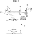
- a microscope 1 is a confocal scanning microscope and is provided with a laser light source 2 that emits laser light; a dichroic mirror 3 that splits the laser light and fluorescence from a specimen A; a scanning unit (scanning portion) 4 that two-dimensionally scans the laser light on the specimen; an objective lens (objective optical system) 5; a confocal lens 6; a confocal aperture 7 having a pinhole at a position conjugate with a focal position of the objective lens 5; a collimating lens 8; and a detection optical system 10.
- the laser light source 2 emits laser light (excitation light) that generates fluorescence by exciting a fluorescent material in the specimen A.
- the dichroic mirror 3 reflects the laser light from the laser light source 2 and, on the other hand, transmits the fluorescence generated at the specimen A due to the irradiation with the laser light.
- the scanning unit 4 has a pair of galvanometer mirrors (not shown) and is driven by a raster scanning method by changing the swivel angles of the pair of galvanometer mirrors. Accordingly, the laser light from the laser light source 2 can be two-dimensionally scanned on the specimen A.
- the objective lens 5 focuses the laser light from the laser light source 2 on the specimen A and, on the other hand, collects the fluorescence generated at the specimen A.
- the fluorescence collected by the objective lens 5 follows the reverse route to that taken by the laser light and passes through the dichroic mirror 3 via the scanning unit 4.
- the confocal lens 6 focuses the fluorescence from the specimen A that has passed through the dichroic mirror 3.
- the confocal aperture 7 allows only florescence generated at a focal plane in a specimen A to pass therethrough. Accordingly, fluorescence generated at positions other than the focal position of the objective lens 5 is blocked.
- the collimating lens 8 causes the fluorescence that has passed through the confocal aperture 7 to enter the detection optical system 10 as a collimated beam.
- the detection optical system 10 is provided with a transmissive VPH diffraction grating 11 that disperses the fluorescence from the specimen A into a plurality of wavelength bands; a reflecting mirror (reflecting portion) 12 that reflects the florescence that has passed through the VPH diffraction grating 11; an imaging lens 14 that images the fluorescence reflected by the reflecting mirror 12; and a light detection portion 15 that detects the fluorescence imaged by the imaging lens 14.
- a transmissive VPH diffraction grating 11 that disperses the fluorescence from the specimen A into a plurality of wavelength bands
- a reflecting mirror (reflecting portion) 12 that reflects the florescence that has passed through the VPH diffraction grating 11
- an imaging lens 14 that images the fluorescence reflected by the reflecting mirror 12
- a light detection portion 15 that detects the fluorescence imaged by the imaging lens 14.
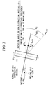
- the VPH diffraction grating 11 is a transmissive Volume Phase Holographic diffraction grating, and has a VPH layer that periodically changes the refractive index along a principal line PL, as shown in Fig. 3 .
- the VPH diffraction grating 11 disperses the fluorescence from the specimen A into the plurality of wavelength bands.
- the VPH diffraction grating 11 is a transmissive diffraction grating that emits a zero-order diffracted beam in a direction parallel to the incident light and that, from the zero-order diffracted beam, emits first-order diffracted beams at different angles for the individual wavelengths, and has diffraction properties showing a higher diffraction efficiency in a wider wavelength band as compared with the reflective diffraction grating.
- an incident angle ⁇ and a diffraction angle ⁇ satisfy the following expression.
- N is the grating frequency of a diffraction grating
- ⁇ is the incident wavelength into the diffraction grating
- the VPH diffraction grating 11 in this embodiment has a rotating mechanism (not shown) that rotates the VPH diffraction grating 11 about an axial line L that is perpendicular to an incident optical axis for the fluorescence from the specimen A and perpendicular to an optical axis of an emitted beam diffracted by the VPH diffraction grating 11.
- a rotating mechanism (not shown) that rotates the VPH diffraction grating 11 about an axial line L that is perpendicular to an incident optical axis for the fluorescence from the specimen A and perpendicular to an optical axis of an emitted beam diffracted by the VPH diffraction grating 11.
- the reflecting mirror 12 is provided with a reflecting-portion rotating mechanism (correcting portion) 13 that, in synchronization with the above-described rotating mechanism, rotates the reflecting mirror 12 about an axial line that is perpendicular to the incident optical axis of the fluorescence from the specimen A.
- the incident position on the light detection portion 15 is corrected in accordance with a displacement of the optical axis due to the rotation of the VPH diffraction grating 11. Note that a specific method of correcting the incident position on the light detection portion 15 will be described later.
- the light detection portion 15 is a multichannel PMT (photomultiplier tube) in which a plurality of channels (reference signs 15a, 15b, and so on) for detecting the fluorescence from the specimen A are arranged in the direction in which the fluorescence is dispersed.
- the light detection portion 15 separately detects the beams in the plurality of wavelength bands dispersed by the VPH diffraction grating 11 by means of the individual channels.
- the laser light emitted from the laser light source 2 is reflected by the dichroic mirror 3 and enters the objective lens 5 via the scanning unit 4.
- the objective lens 5 radiates the laser light by focusing it at one point in the specimen A. Accordingly, the fluorescent material in the specimen A is excited by the laser light, generating fluorescence.
- the fluorescence from the specimen A travels in reverse along the same optical path as the laser light, and is made incident on the dichroic mirror 3 via the objective lens 5 and the scanning unit 4. Then, the fluorescence from the specimen A passes through the dichroic mirror 3 and is focused by the confocal lens 6. Because the confocal aperture 7 has the pinhole at the position that is optically conjugated with the focal position of the objective lens 5, only the fluorescence generated at the focal position of the objective lens 5 passes through the confocal aperture 7. Subsequently, the fluorescence is converted to a substantially collimated beam by the collimating lens 8 and enters the detection optical system 10.
- the fluorescence from the specimen A is dispersed into beams in a plurality of wavelength bands by means of the VPH diffraction grating 11.
- the fluorescence is diffracted at the VPH diffraction grating 11, and the diffracted beams are separately emitted at different diffraction angles in accordance with the individual wavelengths.
- the first-order diffracted beams (fluorescence) separately emitted at different diffraction angles in accordance with the individual wavelengths are reflected by the reflecting mirror 12 and separately enter the imaging lens 14 at different angles relative to the optical axis in accordance with the individual wavelengths. Accordingly, the first-order diffracted beams separately enter the light detection portion 15 by means of the imaging lens 14 at different positions (channels) in accordance with the individual wavelengths, thus being separately detected by the different channels in accordance with the wavelengths.
- the first-order diffracted beams (fluorescence) detected by the light detection portion 15 are converted to electrical signals, and fluorescence image formation, other analyses, or the like are performed on the basis of the electrical signals related to individual points in the specimen A obtained by scanning the specimen A by means of the scanning unit 4. Then, the fluorescence image or the analysis results are displayed on a display portion (not shown), such as a monitor or the like.
- the VPH diffraction grating 11 is rotated by means of the rotating mechanism (not shown) about the axial line L that is perpendicular to the incident optical axis of the fluorescence from the specimen A and perpendicular to the optical axis of the emitted light diffracted by the VPH diffraction grating 11. Accordingly, the amount of fluorescence light detected by the light detection portion 15 can be enhanced by enhancing the diffraction efficiency of the VPH diffraction grating 11.
- the optical axis of the fluorescence from the specimen A that has passed through the VPH diffraction grating 11 ends up being displaced.
- the reflecting mirror 12 by means of the reflecting-portion rotating mechanism 13 in synchronization with the operation of the rotating mechanism, the incident position on the light detection portion 15 can be corrected in accordance with the displacement of the optical axis due to the rotation of the VPH diffraction grating 11. Accordingly, the fluorescence from the specimen A that has been dispersed by the VPH diffraction grating 11 can reliably be detected at the predetermined positions (channels) of the light detection portion 15, and the dispersion precision thereof can be enhanced.
- the amount of light detected by the light detection portion 15 can be enhanced, and the dispersion precision for the fluorescence from the specimen A can also be enhanced.
- the dispersion precision for the fluorescence from the specimen A can be enhanced, and a size reduction of the apparatus can be achieved by making the optical system compact as a whole.
- the fluorescence from the specimen A that has been dispersed by the VPH diffraction grating 11 (beams in the plurality of wavelength bands) can be simultaneously detected, which makes it possible to perform real-time dispersed-light observation.
- a specific method of correcting the incident position on the light detection portion 15, that is, a specific method of adjusting the rotation angle of the reflecting mirror 12 by means of the reflecting-portion rotating mechanism 13, will be described below by using Figs. 3 and 4 .
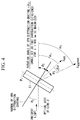
- a calculation method for a shift in the angle of the emission optical axis for the fluorescence from the specimen A will be described here for the case in which the VPH diffraction grating 11 is rotated from the state shown in Fig. 3 to the one shown in Fig. 4 .
- a wavelength ⁇ std at which the diffraction efficiency is maximized when the rotation angle of the VPH diffraction grating 11 is at a standard angle ⁇ 1 is assumed to be 500 nm, and a wavelength ⁇ 600 that needs to be detected is assumed to be 600 nm.
- Fig. 3 shows a state in which the rotation angle of the VPH diffraction grating 11 is at the standard angle ⁇ 1 (a state in which the diffraction efficiency for the standard wavelength ⁇ std is maximized) .
- ⁇ std wavelength for which the VPH diffraction grating 11 achieves the maximum efficiency (design standard wavelength).
- ⁇ difference between the detection target wavelength and the wavelength for which the maximum efficiency is achieved (design standard wavelength ⁇ std ).
- ⁇ 600 detection target wavelength.
- N a constant determined by the properties of the VPH diffraction grating 11.
- ⁇ 1 ' diffraction angle for the design standard wavelength ⁇ std .
- ⁇ 600 ' diffraction angle for the detection wavelength ⁇ 600 (for the case of the state shown in Fig. 3 ).
- ⁇ 2 ' diffraction angle for the case in which the diffraction efficiency is maximized for the detection wavelength ⁇ 600 (the state shown in Fig. 4 ).
- ⁇ 1 emission angle for the detection wavelength ⁇ 600 for the case in which the rotation angle of the VPH diffraction grating is ⁇ 1 ( Fig. 3 ).
- ⁇ 2 emission angle for the detection wavelength ⁇ 600 for the case in which the rotation angle of the VPH diffraction grating is ⁇ 2 ( Fig. 4 ).
- a broken line indicated by ⁇ 600 indicates the optical axis along which a beam of the wavelength ⁇ 600 is emitted in the state shown in Fig. 3 , where the rotation angle of the VPH diffraction grating is ⁇ 1 .
- a solid line indicated by ⁇ 600 max indicates the optical axis along which a beam of wavelength ⁇ 600 is emitted in the state shown in Fig. 4 , where the diffraction efficiency for the detection wavelength ⁇ 600 is maximized.
- ⁇ 1 sin ⁇ 1 N ⁇ std / 2 + sin ⁇ 1 N ⁇ 600 ⁇ ⁇ std / 2
- ⁇ 2 ⁇ 2 ⁇ ⁇ 1 .
- ⁇ 600 ⁇ std + ⁇
- ⁇ 2 sin ⁇ 1 N ⁇ std + ⁇ / 2 ⁇ sin ⁇ 1 N ⁇ std / 2 ⁇ sin ⁇ 1 N ⁇ std / 2 + ⁇
- the shift in the angle of the emission optical axis of the fluorescence from the specimen A is a function that includes only ⁇ , as shown inexpression (6) above.
- the displacement of the optical axis caused by the rotation of the VPH diffraction gratihg 11 can be corrected just by rotating the reflecting mirror 12 by an angle ⁇ /2 about the axial line perpendicular to the incident optical axis of the fluorescence from the specimen A.
- the fluorescence from the specimen A which has been dispersed by the VPH diffraction grating 11 can reliably be detected at the predetermined positions (channels) of the light detection portion 15, and the dispersion precision for the fluorescence from the specimen A can be enhanced.
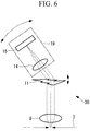
- a detection optical system according to a second embodiment of the present invention will be described with reference to Fig. 5 .
- the same reference signs will be assigned to commonalities with the above-described embodiment, descriptions thereof will be omitted, and differences will mainly be described.
- a detection optical system 20 is provided with a light detection portion 17, which is a single-channel PMT, and a wavelength-selecting slit 16 that selects the wavelength of light that enters the light detection portion 17.
- the light detection portion 17 By employing a single-channel PMT as the light detection portion 17 and by selecting the wavelength of the light that enters the light detection portion 17, which is a single-channel PMT, by means of the wavelength-selecting slit 16, it is possible to detect light having the selected wavelength from the fluorescence (beams in the plurality of wavelength bands) from the specimen A that has been dispersed by the VPH diffraction grating 11. With such a configuration, the cost of the apparatus can be reduced.
- a detection optical system 30 is provided with a light-detection-portion rotating mechanism (correcting portion) 19 that rotates the light detection portion 15 and the imaging lens 14 about the rotation axis of the VPH diffraction grating 11.
- the correcting portion that corrects the incident positions on the light detection portion 15 By configuring the correcting portion that corrects the incident positions on the light detection portion 15 in this way, the dispersion precision for the fluorescence from the specimen A can be enhanced, and the loss of fluorescence from the specimen A at optical members such as the reflecting mirror 12 or the like in the first embodiment can also be eliminated, which makes it possible to enhance the detection efficiency of the light detection portion 15.
- the light-detection-portion rotating mechanism 19 can correct the displacement of the optical axis caused by the rotation of the VPH diffraction grating 11 just by rotating the light detection portion 15 and the imaging lens 14 by the angle ⁇ about the rotation axis of the VPH diffraction grating 11 on the basis-of the above-described expression (6).
Landscapes
- Physics & Mathematics (AREA)
- Spectroscopy & Molecular Physics (AREA)
- General Physics & Mathematics (AREA)
- Chemical & Material Sciences (AREA)
- Analytical Chemistry (AREA)
- Optics & Photonics (AREA)
- Investigating, Analyzing Materials By Fluorescence Or Luminescence (AREA)
- Microscoopes, Condenser (AREA)
Applications Claiming Priority (1)
| Application Number | Priority Date | Filing Date | Title |
|---|---|---|---|
| JP2011252674A JP5945400B2 (ja) | 2011-11-18 | 2011-11-18 | 検出光学系および走査型顕微鏡 |
Publications (2)
| Publication Number | Publication Date |
|---|---|
| EP2594979A1 EP2594979A1 (en) | 2013-05-22 |
| EP2594979B1 true EP2594979B1 (en) | 2019-03-27 |
Family
ID=47323809
Family Applications (1)
| Application Number | Title | Priority Date | Filing Date |
|---|---|---|---|
| EP12007625.2A Not-in-force EP2594979B1 (en) | 2011-11-18 | 2012-11-09 | Detection optical system and scanning microscope |
Country Status (3)
| Country | Link |
|---|---|
| US (1) | US8885162B2 (enExample) |
| EP (1) | EP2594979B1 (enExample) |
| JP (1) | JP5945400B2 (enExample) |
Families Citing this family (12)
| Publication number | Priority date | Publication date | Assignee | Title |
|---|---|---|---|---|
| JP5945400B2 (ja) * | 2011-11-18 | 2016-07-05 | オリンパス株式会社 | 検出光学系および走査型顕微鏡 |
| JP6408796B2 (ja) | 2014-06-11 | 2018-10-17 | オリンパス株式会社 | レーザ顕微鏡装置 |
| JP6456617B2 (ja) * | 2014-07-15 | 2019-01-23 | オリンパス株式会社 | 顕微鏡装置 |
| KR102240270B1 (ko) | 2014-07-21 | 2021-04-14 | 삼성전자주식회사 | 광 변환 모듈 및 광학 측정 시스템 |
| WO2016061710A1 (zh) * | 2014-10-21 | 2016-04-28 | 清华大学 | 一种快速宽视场体全息荧光显微成像系统 |
| CN105352923B (zh) * | 2014-10-21 | 2018-08-03 | 清华大学 | 一种快速宽视场体全息荧光显微成像系统 |
| JP6375239B2 (ja) * | 2015-02-05 | 2018-08-15 | オリンパス株式会社 | レーザ顕微鏡装置 |
| KR101884118B1 (ko) * | 2017-03-14 | 2018-07-31 | 한양대학교 산학협력단 | 투과 회절 격자 기반 분광기 |
| DE102017127122B4 (de) * | 2017-11-17 | 2022-05-05 | Endress+Hauser Conducta Gmbh+Co. Kg | Spektrometrisches Messgerät |
| TR202010646A1 (tr) * | 2020-07-06 | 2022-01-21 | Orta Dogu Teknik Ueniversitesi | Deği̇şken kirinim opti̇k elemanli opti̇k spektrometre |
| WO2022025728A1 (ko) * | 2020-07-30 | 2022-02-03 | 주식회사 스킨어세이 | 분광기 |
| US20230304922A1 (en) | 2022-03-23 | 2023-09-28 | Tetsuroh Tatebe | Spectroscope and analysis system |
Family Cites Families (18)
| Publication number | Priority date | Publication date | Assignee | Title |
|---|---|---|---|---|
| US3600093A (en) * | 1969-11-10 | 1971-08-17 | Sperry Rand Corp | Continuously blazed optical monochromator |
| DE10038049A1 (de) * | 2000-08-02 | 2002-02-14 | Leica Microsystems | Optische Anordnung zur Selektion und Detektion des Spektalbereichs eines Lichtstrahls |
| US6583873B1 (en) * | 2000-09-25 | 2003-06-24 | The Carnegie Institution Of Washington | Optical devices having a wavelength-tunable dispersion assembly that has a volume dispersive diffraction grating |
| TW538258B (en) * | 2002-07-16 | 2003-06-21 | Ind Tech Res Inst | Grating interferometer device with tunable resolution |
| TWI245473B (en) * | 2003-06-30 | 2005-12-11 | Delta Electronics Inc | Tunable laser source and wavelength selecting method thereof |
| JP4646506B2 (ja) * | 2003-09-11 | 2011-03-09 | オリンパス株式会社 | レーザ走査型顕微鏡 |
| JP4633386B2 (ja) * | 2004-05-25 | 2011-02-16 | オリンパス株式会社 | 走査型レーザ顕微鏡及びそれを用いたデータ取得方法 |
| JP4804727B2 (ja) | 2004-06-24 | 2011-11-02 | オリンパス株式会社 | 光走査型共焦点顕微鏡 |
| JP4645173B2 (ja) * | 2004-11-26 | 2011-03-09 | 株式会社ニコン | 分光器、及びこれを備えている顕微分光装置 |
| DE102005042890B4 (de) * | 2005-09-09 | 2007-05-31 | Leica Microsystems Cms Gmbh | Konfokalmikroskop und Verfahren zur Detektion mit einem Konfokalmikroskop |
| US7564547B2 (en) | 2005-11-07 | 2009-07-21 | Wafermasters, Inc. | Spectroscopy system |
| US20070160325A1 (en) * | 2006-01-11 | 2007-07-12 | Hyungbin Son | Angle-tunable transmissive grating |
| KR100817726B1 (ko) * | 2008-01-18 | 2008-03-31 | 주식회사 나노베이스 | 파장 가변 장치 및 그 방법 |
| KR100885537B1 (ko) * | 2008-09-03 | 2009-02-26 | 주식회사 나노베이스 | 파장 가변 분광계 및 그 파장 가변 방법 |
| JP2011197351A (ja) * | 2010-03-19 | 2011-10-06 | Olympus Corp | 反射型回折格子、及び、それを用いた分光器及びパルス整形器 |
| JP5541972B2 (ja) * | 2010-06-09 | 2014-07-09 | オリンパス株式会社 | 走査型共焦点顕微鏡 |
| JP5965099B2 (ja) * | 2010-11-05 | 2016-08-03 | 住友電気工業株式会社 | 光学装置およびその調整方法 |
| JP5945400B2 (ja) * | 2011-11-18 | 2016-07-05 | オリンパス株式会社 | 検出光学系および走査型顕微鏡 |
-
2011
- 2011-11-18 JP JP2011252674A patent/JP5945400B2/ja not_active Expired - Fee Related
-
2012
- 2012-11-06 US US13/669,634 patent/US8885162B2/en active Active
- 2012-11-09 EP EP12007625.2A patent/EP2594979B1/en not_active Not-in-force
Non-Patent Citations (1)
| Title |
|---|
| None * |
Also Published As
| Publication number | Publication date |
|---|---|
| US8885162B2 (en) | 2014-11-11 |
| JP5945400B2 (ja) | 2016-07-05 |
| US20130128268A1 (en) | 2013-05-23 |
| JP2013109082A (ja) | 2013-06-06 |
| EP2594979A1 (en) | 2013-05-22 |
Similar Documents
| Publication | Publication Date | Title |
|---|---|---|
| EP2594979B1 (en) | Detection optical system and scanning microscope | |
| EP3726274B1 (en) | Structured illumination microscope apparatus and an image forming apparatus | |
| US9989754B2 (en) | Light scanning microscope with spectral detection | |
| EP2395380B1 (en) | Scanning microscope | |
| EP2720026B1 (en) | Raman microscope and raman spectrometric method | |
| US8098374B2 (en) | Highly sensitive spectroscopic unit | |
| EP2124040A1 (en) | Laser microscope apparatus | |
| JP5567887B2 (ja) | 分光装置 | |
| JP5541978B2 (ja) | レーザ走査型顕微鏡 | |
| US7151633B2 (en) | Scanning microscope | |
| JP4434882B2 (ja) | レーザ走査型蛍光観察装置 | |
| JP4645173B2 (ja) | 分光器、及びこれを備えている顕微分光装置 | |
| JP4086182B2 (ja) | 分光器およびこれを用いた共焦点光学系、走査型光学顕微鏡 | |
| JP4331454B2 (ja) | 走査型レーザ顕微鏡 | |
| JP5371362B2 (ja) | レーザ顕微鏡装置 | |
| JP5861873B2 (ja) | 分光器及び顕微分光システム | |
| JP2003185927A (ja) | 走査型レーザー顕微鏡 | |
| JP5787151B2 (ja) | 分光ユニット及び走査型顕微鏡 | |
| JP5576649B2 (ja) | 分光器、及び、それを備えた光学装置 | |
| JP2007304103A (ja) | 分光器およびこれを用いた共焦点光学系、走査型光学顕微鏡 | |
| JP5583515B2 (ja) | レーザ顕微鏡用照明装置およびレーザ顕微鏡 | |
| JP2013195264A (ja) | 分光器及び顕微分光システム | |
| US20250389940A1 (en) | Detection arrangement, cascaded detection arrangement, and optical scanning microscope | |
| JP2002277744A (ja) | 走査型光学顕微鏡 | |
| JP2001264169A (ja) | 分光装置 |
Legal Events
| Date | Code | Title | Description |
|---|---|---|---|
| PUAI | Public reference made under article 153(3) epc to a published international application that has entered the european phase |
Free format text: ORIGINAL CODE: 0009012 |
|
| AK | Designated contracting states |
Kind code of ref document: A1 Designated state(s): AL AT BE BG CH CY CZ DE DK EE ES FI FR GB GR HR HU IE IS IT LI LT LU LV MC MK MT NL NO PL PT RO RS SE SI SK SM TR |
|
| AX | Request for extension of the european patent |
Extension state: BA ME |
|
| 17P | Request for examination filed |
Effective date: 20131029 |
|
| RBV | Designated contracting states (corrected) |
Designated state(s): AL AT BE BG CH CY CZ DE DK EE ES FI FR GB GR HR HU IE IS IT LI LT LU LV MC MK MT NL NO PL PT RO RS SE SI SK SM TR |
|
| RAP1 | Party data changed (applicant data changed or rights of an application transferred) |
Owner name: OLYMPUS CORPORATION |
|
| RAP1 | Party data changed (applicant data changed or rights of an application transferred) |
Owner name: OLYMPUS CORPORATION |
|
| RIN1 | Information on inventor provided before grant (corrected) |
Inventor name: TOMIOKA, MASAHARU |
|
| STAA | Information on the status of an ep patent application or granted ep patent |
Free format text: STATUS: EXAMINATION IS IN PROGRESS |
|
| 17Q | First examination report despatched |
Effective date: 20170410 |
|
| GRAP | Despatch of communication of intention to grant a patent |
Free format text: ORIGINAL CODE: EPIDOSNIGR1 |
|
| STAA | Information on the status of an ep patent application or granted ep patent |
Free format text: STATUS: GRANT OF PATENT IS INTENDED |
|
| INTG | Intention to grant announced |
Effective date: 20181122 |
|
| RIN1 | Information on inventor provided before grant (corrected) |
Inventor name: TOMIOKA, MASAHARU |
|
| GRAS | Grant fee paid |
Free format text: ORIGINAL CODE: EPIDOSNIGR3 |
|
| GRAA | (expected) grant |
Free format text: ORIGINAL CODE: 0009210 |
|
| STAA | Information on the status of an ep patent application or granted ep patent |
Free format text: STATUS: THE PATENT HAS BEEN GRANTED |
|
| AK | Designated contracting states |
Kind code of ref document: B1 Designated state(s): AL AT BE BG CH CY CZ DE DK EE ES FI FR GB GR HR HU IE IS IT LI LT LU LV MC MK MT NL NO PL PT RO RS SE SI SK SM TR |
|
| REG | Reference to a national code |
Ref country code: GB Ref legal event code: FG4D |
|
| REG | Reference to a national code |
Ref country code: CH Ref legal event code: EP |
|
| REG | Reference to a national code |
Ref country code: AT Ref legal event code: REF Ref document number: 1113777 Country of ref document: AT Kind code of ref document: T Effective date: 20190415 |
|
| REG | Reference to a national code |
Ref country code: IE Ref legal event code: FG4D |
|
| REG | Reference to a national code |
Ref country code: DE Ref legal event code: R096 Ref document number: 602012058188 Country of ref document: DE |
|
| PG25 | Lapsed in a contracting state [announced via postgrant information from national office to epo] |
Ref country code: SE Free format text: LAPSE BECAUSE OF FAILURE TO SUBMIT A TRANSLATION OF THE DESCRIPTION OR TO PAY THE FEE WITHIN THE PRESCRIBED TIME-LIMIT Effective date: 20190327 Ref country code: FI Free format text: LAPSE BECAUSE OF FAILURE TO SUBMIT A TRANSLATION OF THE DESCRIPTION OR TO PAY THE FEE WITHIN THE PRESCRIBED TIME-LIMIT Effective date: 20190327 Ref country code: LT Free format text: LAPSE BECAUSE OF FAILURE TO SUBMIT A TRANSLATION OF THE DESCRIPTION OR TO PAY THE FEE WITHIN THE PRESCRIBED TIME-LIMIT Effective date: 20190327 Ref country code: NO Free format text: LAPSE BECAUSE OF FAILURE TO SUBMIT A TRANSLATION OF THE DESCRIPTION OR TO PAY THE FEE WITHIN THE PRESCRIBED TIME-LIMIT Effective date: 20190627 |
|
| REG | Reference to a national code |
Ref country code: NL Ref legal event code: MP Effective date: 20190327 |
|
| PG25 | Lapsed in a contracting state [announced via postgrant information from national office to epo] |
Ref country code: BG Free format text: LAPSE BECAUSE OF FAILURE TO SUBMIT A TRANSLATION OF THE DESCRIPTION OR TO PAY THE FEE WITHIN THE PRESCRIBED TIME-LIMIT Effective date: 20190627 Ref country code: HR Free format text: LAPSE BECAUSE OF FAILURE TO SUBMIT A TRANSLATION OF THE DESCRIPTION OR TO PAY THE FEE WITHIN THE PRESCRIBED TIME-LIMIT Effective date: 20190327 Ref country code: GR Free format text: LAPSE BECAUSE OF FAILURE TO SUBMIT A TRANSLATION OF THE DESCRIPTION OR TO PAY THE FEE WITHIN THE PRESCRIBED TIME-LIMIT Effective date: 20190628 Ref country code: NL Free format text: LAPSE BECAUSE OF FAILURE TO SUBMIT A TRANSLATION OF THE DESCRIPTION OR TO PAY THE FEE WITHIN THE PRESCRIBED TIME-LIMIT Effective date: 20190327 Ref country code: LV Free format text: LAPSE BECAUSE OF FAILURE TO SUBMIT A TRANSLATION OF THE DESCRIPTION OR TO PAY THE FEE WITHIN THE PRESCRIBED TIME-LIMIT Effective date: 20190327 Ref country code: RS Free format text: LAPSE BECAUSE OF FAILURE TO SUBMIT A TRANSLATION OF THE DESCRIPTION OR TO PAY THE FEE WITHIN THE PRESCRIBED TIME-LIMIT Effective date: 20190327 |
|
| REG | Reference to a national code |
Ref country code: AT Ref legal event code: MK05 Ref document number: 1113777 Country of ref document: AT Kind code of ref document: T Effective date: 20190327 |
|
| PG25 | Lapsed in a contracting state [announced via postgrant information from national office to epo] |
Ref country code: IT Free format text: LAPSE BECAUSE OF FAILURE TO SUBMIT A TRANSLATION OF THE DESCRIPTION OR TO PAY THE FEE WITHIN THE PRESCRIBED TIME-LIMIT Effective date: 20190327 Ref country code: ES Free format text: LAPSE BECAUSE OF FAILURE TO SUBMIT A TRANSLATION OF THE DESCRIPTION OR TO PAY THE FEE WITHIN THE PRESCRIBED TIME-LIMIT Effective date: 20190327 Ref country code: RO Free format text: LAPSE BECAUSE OF FAILURE TO SUBMIT A TRANSLATION OF THE DESCRIPTION OR TO PAY THE FEE WITHIN THE PRESCRIBED TIME-LIMIT Effective date: 20190327 Ref country code: CZ Free format text: LAPSE BECAUSE OF FAILURE TO SUBMIT A TRANSLATION OF THE DESCRIPTION OR TO PAY THE FEE WITHIN THE PRESCRIBED TIME-LIMIT Effective date: 20190327 Ref country code: EE Free format text: LAPSE BECAUSE OF FAILURE TO SUBMIT A TRANSLATION OF THE DESCRIPTION OR TO PAY THE FEE WITHIN THE PRESCRIBED TIME-LIMIT Effective date: 20190327 Ref country code: AL Free format text: LAPSE BECAUSE OF FAILURE TO SUBMIT A TRANSLATION OF THE DESCRIPTION OR TO PAY THE FEE WITHIN THE PRESCRIBED TIME-LIMIT Effective date: 20190327 Ref country code: PT Free format text: LAPSE BECAUSE OF FAILURE TO SUBMIT A TRANSLATION OF THE DESCRIPTION OR TO PAY THE FEE WITHIN THE PRESCRIBED TIME-LIMIT Effective date: 20190727 Ref country code: SK Free format text: LAPSE BECAUSE OF FAILURE TO SUBMIT A TRANSLATION OF THE DESCRIPTION OR TO PAY THE FEE WITHIN THE PRESCRIBED TIME-LIMIT Effective date: 20190327 |
|
| PG25 | Lapsed in a contracting state [announced via postgrant information from national office to epo] |
Ref country code: PL Free format text: LAPSE BECAUSE OF FAILURE TO SUBMIT A TRANSLATION OF THE DESCRIPTION OR TO PAY THE FEE WITHIN THE PRESCRIBED TIME-LIMIT Effective date: 20190327 Ref country code: SM Free format text: LAPSE BECAUSE OF FAILURE TO SUBMIT A TRANSLATION OF THE DESCRIPTION OR TO PAY THE FEE WITHIN THE PRESCRIBED TIME-LIMIT Effective date: 20190327 |
|
| PG25 | Lapsed in a contracting state [announced via postgrant information from national office to epo] |
Ref country code: IS Free format text: LAPSE BECAUSE OF FAILURE TO SUBMIT A TRANSLATION OF THE DESCRIPTION OR TO PAY THE FEE WITHIN THE PRESCRIBED TIME-LIMIT Effective date: 20190727 Ref country code: AT Free format text: LAPSE BECAUSE OF FAILURE TO SUBMIT A TRANSLATION OF THE DESCRIPTION OR TO PAY THE FEE WITHIN THE PRESCRIBED TIME-LIMIT Effective date: 20190327 |
|
| REG | Reference to a national code |
Ref country code: DE Ref legal event code: R097 Ref document number: 602012058188 Country of ref document: DE |
|
| PG25 | Lapsed in a contracting state [announced via postgrant information from national office to epo] |
Ref country code: DK Free format text: LAPSE BECAUSE OF FAILURE TO SUBMIT A TRANSLATION OF THE DESCRIPTION OR TO PAY THE FEE WITHIN THE PRESCRIBED TIME-LIMIT Effective date: 20190327 |
|
| PLBE | No opposition filed within time limit |
Free format text: ORIGINAL CODE: 0009261 |
|
| STAA | Information on the status of an ep patent application or granted ep patent |
Free format text: STATUS: NO OPPOSITION FILED WITHIN TIME LIMIT |
|
| PG25 | Lapsed in a contracting state [announced via postgrant information from national office to epo] |
Ref country code: SI Free format text: LAPSE BECAUSE OF FAILURE TO SUBMIT A TRANSLATION OF THE DESCRIPTION OR TO PAY THE FEE WITHIN THE PRESCRIBED TIME-LIMIT Effective date: 20190327 |
|
| 26N | No opposition filed |
Effective date: 20200103 |
|
| PG25 | Lapsed in a contracting state [announced via postgrant information from national office to epo] |
Ref country code: TR Free format text: LAPSE BECAUSE OF FAILURE TO SUBMIT A TRANSLATION OF THE DESCRIPTION OR TO PAY THE FEE WITHIN THE PRESCRIBED TIME-LIMIT Effective date: 20190327 |
|
| REG | Reference to a national code |
Ref country code: DE Ref legal event code: R119 Ref document number: 602012058188 Country of ref document: DE |
|
| REG | Reference to a national code |
Ref country code: CH Ref legal event code: PL |
|
| PG25 | Lapsed in a contracting state [announced via postgrant information from national office to epo] |
Ref country code: LU Free format text: LAPSE BECAUSE OF NON-PAYMENT OF DUE FEES Effective date: 20191109 Ref country code: LI Free format text: LAPSE BECAUSE OF NON-PAYMENT OF DUE FEES Effective date: 20191130 Ref country code: CH Free format text: LAPSE BECAUSE OF NON-PAYMENT OF DUE FEES Effective date: 20191130 Ref country code: MC Free format text: LAPSE BECAUSE OF FAILURE TO SUBMIT A TRANSLATION OF THE DESCRIPTION OR TO PAY THE FEE WITHIN THE PRESCRIBED TIME-LIMIT Effective date: 20190327 |
|
| REG | Reference to a national code |
Ref country code: BE Ref legal event code: MM Effective date: 20191130 |
|
| GBPC | Gb: european patent ceased through non-payment of renewal fee |
Effective date: 20191109 |
|
| PG25 | Lapsed in a contracting state [announced via postgrant information from national office to epo] |
Ref country code: IE Free format text: LAPSE BECAUSE OF NON-PAYMENT OF DUE FEES Effective date: 20191109 Ref country code: GB Free format text: LAPSE BECAUSE OF NON-PAYMENT OF DUE FEES Effective date: 20191109 Ref country code: FR Free format text: LAPSE BECAUSE OF NON-PAYMENT OF DUE FEES Effective date: 20191130 Ref country code: DE Free format text: LAPSE BECAUSE OF NON-PAYMENT OF DUE FEES Effective date: 20200603 |
|
| PG25 | Lapsed in a contracting state [announced via postgrant information from national office to epo] |
Ref country code: BE Free format text: LAPSE BECAUSE OF NON-PAYMENT OF DUE FEES Effective date: 20191130 |
|
| PG25 | Lapsed in a contracting state [announced via postgrant information from national office to epo] |
Ref country code: CY Free format text: LAPSE BECAUSE OF FAILURE TO SUBMIT A TRANSLATION OF THE DESCRIPTION OR TO PAY THE FEE WITHIN THE PRESCRIBED TIME-LIMIT Effective date: 20190327 |
|
| PG25 | Lapsed in a contracting state [announced via postgrant information from national office to epo] |
Ref country code: HU Free format text: LAPSE BECAUSE OF FAILURE TO SUBMIT A TRANSLATION OF THE DESCRIPTION OR TO PAY THE FEE WITHIN THE PRESCRIBED TIME-LIMIT; INVALID AB INITIO Effective date: 20121109 Ref country code: MT Free format text: LAPSE BECAUSE OF FAILURE TO SUBMIT A TRANSLATION OF THE DESCRIPTION OR TO PAY THE FEE WITHIN THE PRESCRIBED TIME-LIMIT Effective date: 20190327 |
|
| PG25 | Lapsed in a contracting state [announced via postgrant information from national office to epo] |
Ref country code: MK Free format text: LAPSE BECAUSE OF FAILURE TO SUBMIT A TRANSLATION OF THE DESCRIPTION OR TO PAY THE FEE WITHIN THE PRESCRIBED TIME-LIMIT Effective date: 20190327 |