EP2594793A2 - Verdichter - Google Patents
Verdichter Download PDFInfo
- Publication number
- EP2594793A2 EP2594793A2 EP12189680.7A EP12189680A EP2594793A2 EP 2594793 A2 EP2594793 A2 EP 2594793A2 EP 12189680 A EP12189680 A EP 12189680A EP 2594793 A2 EP2594793 A2 EP 2594793A2
- Authority
- EP
- European Patent Office
- Prior art keywords
- valve
- suction
- base plate
- suction port
- fixing
- Prior art date
- Legal status (The legal status is an assumption and is not a legal conclusion. Google has not performed a legal analysis and makes no representation as to the accuracy of the status listed.)
- Granted
Links
- 238000007789 sealing Methods 0.000 claims abstract description 53
- 230000006835 compression Effects 0.000 claims abstract description 23
- 238000007906 compression Methods 0.000 claims abstract description 23
- 235000014676 Phragmites communis Nutrition 0.000 claims description 51
- 238000004080 punching Methods 0.000 claims description 2
- 230000007423 decrease Effects 0.000 description 11
- 239000003507 refrigerant Substances 0.000 description 4
- 230000003247 decreasing effect Effects 0.000 description 3
- 238000006073 displacement reaction Methods 0.000 description 3
- 239000000463 material Substances 0.000 description 3
- 239000000314 lubricant Substances 0.000 description 2
- 238000004519 manufacturing process Methods 0.000 description 2
- 230000001629 suppression Effects 0.000 description 2
- 229910000639 Spring steel Inorganic materials 0.000 description 1
- 238000005520 cutting process Methods 0.000 description 1
- 230000005489 elastic deformation Effects 0.000 description 1
- 230000012447 hatching Effects 0.000 description 1
- 238000003754 machining Methods 0.000 description 1
- 239000003595 mist Substances 0.000 description 1
- 230000002093 peripheral effect Effects 0.000 description 1
- 238000005498 polishing Methods 0.000 description 1
- 230000010349 pulsation Effects 0.000 description 1
Images


Classifications
-
- F—MECHANICAL ENGINEERING; LIGHTING; HEATING; WEAPONS; BLASTING
- F04—POSITIVE - DISPLACEMENT MACHINES FOR LIQUIDS; PUMPS FOR LIQUIDS OR ELASTIC FLUIDS
- F04B—POSITIVE-DISPLACEMENT MACHINES FOR LIQUIDS; PUMPS
- F04B39/00—Component parts, details, or accessories, of pumps or pumping systems specially adapted for elastic fluids, not otherwise provided for in, or of interest apart from, groups F04B25/00 - F04B37/00
- F04B39/10—Adaptations or arrangements of distribution members
- F04B39/1073—Adaptations or arrangements of distribution members the members being reed valves
-
- F—MECHANICAL ENGINEERING; LIGHTING; HEATING; WEAPONS; BLASTING
- F04—POSITIVE - DISPLACEMENT MACHINES FOR LIQUIDS; PUMPS FOR LIQUIDS OR ELASTIC FLUIDS
- F04B—POSITIVE-DISPLACEMENT MACHINES FOR LIQUIDS; PUMPS
- F04B27/00—Multi-cylinder pumps specially adapted for elastic fluids and characterised by number or arrangement of cylinders
- F04B27/08—Multi-cylinder pumps specially adapted for elastic fluids and characterised by number or arrangement of cylinders having cylinders coaxial with, or parallel or inclined to, main shaft axis
- F04B27/14—Control
-
- F—MECHANICAL ENGINEERING; LIGHTING; HEATING; WEAPONS; BLASTING
- F04—POSITIVE - DISPLACEMENT MACHINES FOR LIQUIDS; PUMPS FOR LIQUIDS OR ELASTIC FLUIDS
- F04B—POSITIVE-DISPLACEMENT MACHINES FOR LIQUIDS; PUMPS
- F04B27/00—Multi-cylinder pumps specially adapted for elastic fluids and characterised by number or arrangement of cylinders
- F04B27/08—Multi-cylinder pumps specially adapted for elastic fluids and characterised by number or arrangement of cylinders having cylinders coaxial with, or parallel or inclined to, main shaft axis
- F04B27/10—Multi-cylinder pumps specially adapted for elastic fluids and characterised by number or arrangement of cylinders having cylinders coaxial with, or parallel or inclined to, main shaft axis having stationary cylinders
- F04B27/1009—Distribution members
-
- F—MECHANICAL ENGINEERING; LIGHTING; HEATING; WEAPONS; BLASTING
- F04—POSITIVE - DISPLACEMENT MACHINES FOR LIQUIDS; PUMPS FOR LIQUIDS OR ELASTIC FLUIDS
- F04B—POSITIVE-DISPLACEMENT MACHINES FOR LIQUIDS; PUMPS
- F04B39/00—Component parts, details, or accessories, of pumps or pumping systems specially adapted for elastic fluids, not otherwise provided for in, or of interest apart from, groups F04B25/00 - F04B37/00
- F04B39/10—Adaptations or arrangements of distribution members
-
- F—MECHANICAL ENGINEERING; LIGHTING; HEATING; WEAPONS; BLASTING
- F04—POSITIVE - DISPLACEMENT MACHINES FOR LIQUIDS; PUMPS FOR LIQUIDS OR ELASTIC FLUIDS
- F04B—POSITIVE-DISPLACEMENT MACHINES FOR LIQUIDS; PUMPS
- F04B39/00—Component parts, details, or accessories, of pumps or pumping systems specially adapted for elastic fluids, not otherwise provided for in, or of interest apart from, groups F04B25/00 - F04B37/00
- F04B39/10—Adaptations or arrangements of distribution members
- F04B39/1066—Valve plates
Definitions
- the present invention relates to a compressor.
- a compressor disclosed in Japanese Laid-Open Patent Publication No. 2009-235913 is publicly known.
- the compressor has a valve base plate arranged between a suction chamber and a compression chamber.
- the valve base plate has a suction port, which extends through the valve base plate and allows communication between the suction chamber and the compression chamber.
- the suction port is selectively opened and closed by a suction reed valve, which is arranged in the suction chamber.
- the suction reed valve is elastically deformable and formed using a plate material having front and back surfaces, which extend parallel to each other when in a normal state.
- the suction reed valve has a fixing portion fixed to the valve base plate, a base portion that extends longitudinally from the fixing portion and can be lifted from the valve base plate, and a valve portion that extends from the base portion toward the distal longitudinal end to selectively open and close the suction port.
- the valve base plate is arranged in the suction chamber and has a fixing surface.
- the fixing portion is fixed to the fixing surface through contact between a back surface of the fixing portion and the fixing surface.
- the valve base plate includes a sealing surface, which is flush with the fixing surface and capable of contacting a back surface of the valve portion in an annular manner at a position around the suction port.
- the valve base plate also has an annular groove, which is located on the outer side of the sealing surface in a manner recessed with respect to the fixing surface and arranged around the full circumference of the suction port.
- the inventors of the present invention analyzed details of the conventional compressor. As a result of the analysis, they focused attention on thinning of the suction reed valve and the instant at which the suction reed valve closes.
- a thin suction reed valve is easily flexed and thus allows a smooth gas flow between the reed valve and the valve base plate. This prevents resistance from occurring in the gas flow, thus decreasing the power loss.
- a distal zone of the valve portion flexes and sinks deeply into the recessed groove at the instant the suction reed valve closes.
- a middle zone of the valve portion also flexes and sinks deeply into the suction port due to inertial force or the pressure difference between the compression chamber and the suction pressure in a compression stroke. This may cause fatigue fracture in the valve portion, particularly when the compressor operates at high speed. In this case, the durability of the compressor is reduced.
- a compressor that includes a valve base plate and a suction reed valve is provided.
- the valve base plate is arranged between a suction chamber and a compression chamber.
- the valve base plate includes a suction port for permitting communication between the suction chamber and the compression chamber.
- the suction reed valve selectively opens and closes the suction port.
- the suction reed valve is elastically deformable and has an elongated shape having a distal end.
- the suction reed valve includes a fixing portion fixed to the valve base plate, a base portion that extends from the fixing portion in a longitudinal direction of the suction reed valve and selectively contacts and separates from the valve base plate, and a valve portion that extends from the base portion longitudinally toward the distal end and selectively opens and closes the suction port.
- the valve base plate has a fixing surface formed at a side facing the compression chamber. The fixing portion of the suction reed valve is held in contact with and fixed to the fixing surface.
- the valve portion includes a distal zone including an edge portion at the distal end.
- the valve base plate includes a sealing surface flush with the fixing surface, a recessed groove, a receiving surface flush with the fixing surface, and a support surface flush with the fixing surface.
- the sealing surface is capable of contacting the valve portion in an annular manner around the suction port.
- the recessed groove is located on an outer side of the sealing surface and recessed with respect to the fixing surface.
- the recessed groove includes a bottom portion. The recessed groove separates the edge portion of the valve portion from the bottom portion.
- the receiving surface is capable of contacting the distal zone of the valve portion.
- the support surface is capable of contacting a middle zone located on an inner side of the sealing surface of the valve portion.
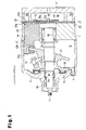
- a compressor according to a first embodiment of the present invention is a swash plate type variable displacement compressor.
- the compressor includes a plurality of cylinder bores 1a, which are formed in a cylinder block 1 and spaced apart at equal angular intervals along a circle.
- the cylinder bores 1a are parallel to one another.
- the cylinder block 1 is arranged between a front housing member 3, which is located in front, and a rear housing member 5, which is located behind. In this state, the cylinder block 1, the front housing member 3, and the rear housing member 5 are fastened together using a plurality of bolts 7.
- the cylinder block 1 and the front housing member 3 form a crank chamber 9 in the cylinder block 1 and the front housing member 3.
- a suction chamber 5a and a plurality of discharge chambers 5b corresponding to the cylinder bores 1a are formed.
- the front housing member 3 has a shaft hole 3a and the cylinder block 1 has a shaft hole 1b.
- a drive shaft 11 is rotationally supported in the shaft holes 3a, 1b through a shaft sealing device 9a and corresponding radial bearings 9b, 9c.
- the drive shaft 11 has a non-illustrated pulley or electromagnetic clutch.
- a non-illustrated belt is wound around the pulley or a pulley of the electromagnetic clutch and driven by the engine of the vehicle.
- a lug plate 13 is press-fitted around the drive shaft 11.
- a thrust bearing 15 is provided between the lug plate 13 and the front housing member 3.
- a swash plate 17 is arranged around the drive shaft 11.
- the drive shaft 11 extends through the swash plate 17.
- the lug plate 13 and the swash plate 17 are connected to each other through a link mechanism 19, which supports the swash plate 17 such that the inclination angle of the swash plate 17 is changeable.
- a piston 21 is reciprocally accommodated in each of the cylinder bores 1a.
- a valve unit 23 is arranged between the cylinder block 1 and the rear housing member 5.
- the valve unit 23 of the compressor includes a suction valve plate 25 contacting the rear end surface of the cylinder block 1, a valve base plate 27 contacting the suction valve plate 25, a discharge valve plate 29 contacting the valve base plate 27, and a retainer plate 31 contacting the discharge valve plate 29.
- the suction valve plate 25 and the valve base plate 27 will be described in detail below.
- a pair of front and rear shoes 33a, 33b is located between the swash plate 17 and each of the pistons 21.
- Each of the pairs of shoes 33a, 33b converts swinging of the swash plate 17 into reciprocation of the associated one of the pistons 21.
- the crank chamber 9 and the suction chamber 5a are connected to each other via a non-illustrated air bleed passage.
- the crank chamber 9 and a discharge chamber 5b are connected to each other via a non-illustrated air supply passage.
- a non-illustrated displacement control valve is located in the air supply passage. The displacement control valve changes the opening of the air supply passage in correspondence with the suction pressure.
- Each of the cylinder bores 1a, the associated one of the pistons 21, and the valve unit 23 form a compression chamber 24.
- a condenser is connected to the discharge chamber 5b of the compressor through a pipe.
- An evaporator is connected to the condenser via an expansion valve through a pipe.
- the evaporator is connected to the suction chamber 5a of the compressor through a pipe.
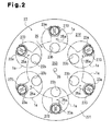
- a plurality of suction ports 23a are each formed in the valve base plate 27 to allow communication between the suction chamber 5a and the corresponding one of the compression chambers 24.
- a suction valve plate 25 is punched out of a plate material formed of spring steel through press working.
- the suction valve plate 25 includes a plurality of suction reed valves 25a, each of which extends radially to selectively open and close the corresponding one of the suction ports 23a.
- each of the suction reed valves 25a is elastically deformable and formed by a plate material having a front surface 251 and a back surface 252, which are parallel to each other when in a normal state.
- a plurality of discharge ports 23b are formed in the suction valve plate 25 and the valve base plate 27 to allow communication between the corresponding compression chambers 24 and the discharge chamber 5b.
- a plurality of discharge reed valves 29a are formed in the discharge valve plate 29 to selectively open and close the corresponding discharge ports 23b.
- Each of the suction reed valves 25a has an elongated shape having a distal end and includes a fixing portion 253, a base portion 254, and a valve portion 255.
- the fixing portion 253 is arranged at the center of the suction valve plate 25 and fixed to the valve base plate 27 through a bolt 35.
- the base portion 254 extends from the fixing portion 253 in the longitudinal direction D, which is a radial direction, and can be lifted from the valve base plate 27.
- the valve portion 255 extends from the base portion 254 to the distal end in the longitudinal direction D to selectively open and close the corresponding suction port 23a.
- the base portion 254 is formed in a rectangular shape having a long side extending in the longitudinal direction D.
- the valve portion 255 is formed in a circular shape having a diameter not less that the length of the short side of the base portion 254. This configuration allows each suction reed valve 25a to open the corresponding suction port 23a by a great opening degree.
- the valve base plate 27 has a fixing surface 271.
- the fixing portion 253 is fixed to the fixing surface 271 with a back surface 252 held in contact with the fixing surface 271.
- the fixing surface 271 is located on the side of the valve base plate 27 that faces the compression chamber 24.
- the valve base plate 27 includes extended portions 272, each of which extends in the longitudinal direction D.
- Each extended portion 272 divides the corresponding suction port 23a into two, left and right, port sections in the direction perpendicular to the longitudinal direction D.
- each suction port 23a is divided into semi-circular port sections 231, 232 by the corresponding extended portion 272.
- each suction port 23a has a circular shape, as a whole, formed by the port sections 231, 232.
- an annular sealing surface 27a is formed between each suction port 23a and the corresponding recessed grooves 273 in the valve base plate 27.
- Each of the sealing surfaces 27a is flush with the fixing surface 271.
- the sealing surface 27a is allowed to contact the back surface 252 of the valve portion 255 in an annular manner around the corresponding suction port 23a.
- Each recessed groove 273 is located on the outer side of the corresponding sealing surface 27a and recessed with respect to the fixing surface 271 such that opposite edge portions of the valve portion 255 and the base portion 254 are spaced from the bottom portion of the recessed groove 273.
- each recessed groove 273 has a C shape and is discontinuous at the distal end in the longitudinal direction D.
- a receiving surface 27b is formed at the position at which the opposite ends of each recessed groove 273 are spaced from each other, or the position between the opposite ends of the recessed groove 273.
- Each of the receiving surfaces 27b is flush with the fixing surface 271.
- Each receiving surface 27b is allowed to contact the back surface 252 in a distal zone of the corresponding valve portion 255.
- the distal zone of each valve portion 255 is located longitudinally distal with respect to the portion at which the back surface of the valve portion 255 contacts the sealing surface 27a of the valve base plate 27 and includes a portion of the edge portion of the valve portion 255.
- the sealing surface 27a and the receiving surface 27b contact the back surface 252 of the valve portion 255 as indicated by the corresponding hatched area.
- An arc 27c in the hatched area represents the boundary between the sealing surface 27a and the receiving surface 27b.
- the sealing surface 27a and the receiving surface 27b are formed continuously from each other.
- a support surface 27d is formed at the center of a surface of the extended portion 272 that faces the corresponding valve portion 255.
- the support surfaces 27d are flush with the fixing surface 271.
- Each of the support surfaces 27d is allowed to contact the back surface 252 at the position corresponding to a middle zone of the corresponding one of the valve portions 255.
- the middle zone of each valve portion 255 is a portion of the valve portion 255 located inward of the portion of the valve portion 255 at which the back side of the valve portion 255 contacts the sealing surface 27a of the valve base plate 27.
- the middle zone of the valve portion 255 includes a central zone corresponding to a central portion of the valve portion 255.
- a communication groove 27e and a communication groove 27f are formed in the extended portion 272 on the front side and the back side, respectively, of each support surface 27d.
- the communication grooves 27e, 27f are recessed with respect to the fixing surface 271. Accordingly, when each valve portion 255 closes, the corresponding communication grooves 27e, 27f allows communication between the port sections 231, 232. Referring to Fig. 5 , the support surface 27d contacts the back surface 252 of the valve portion 255 as indicated by the corresponding hatched area.
- the die 37 has a lower die portion 39 and an upper die portion 41.
- Punch holes 39a, 39d are formed in the lower die portion 39 at positions corresponding to the port sections 231, 232 and extend through the lower die portion 39 in the vertical direction.
- Punches 43, 44 are each received in the corresponding punch holes 39a, 39d movably in the vertical direction.
- Outlet holes 41a, 41b corresponding to the punch holes 39a, 39d are formed in the upper die portion 41 and extend through the upper die portion 41 in the vertical direction.
- Punch holes 41c, 41d are formed in the upper die portion 41 at positions corresponding to the grooves 273 and the communication grooves 27e, 27f and extend through the upper die portion 41 in the vertical direction.
- Punches 46, 48 are received in the corresponding punch holes 41c, 41d movably in the vertical direction.
- valve base plate 27 To form the valve base plate 27 from the workpiece W, the workpiece W is placed between the lower die portion 39 and the upper die portion 41. Then, the punches 43, 44 are raised from below and the punches 46, 48 are lowered from above. As a result, the port sections 231, 232 are formed through punching and the grooves 273 and the communication grooves 27e, 27f are formed through crushing. Afterwards, surface polishing is performed to complete the valve base plate 27. This decreases the manufacturing cost compared to cutting.
- the drive shaft 11 shown in Fig. 1 is rotated to cause the lug plate 13 and the swash plate 17 to rotate synchronously with the drive shaft 11.
- the pistons 21 thus reciprocate in the corresponding cylinder bores 1a by the stroke corresponding to the inclination angle of the swash plate 17.
- the refrigerant gas in the suction chamber 5a is thus drawn into and compressed in the compression chambers 24 and conducted out to the discharge chamber 5b.
- the refrigerant gas compressed by the compressor contains lubricant oil mist.
- the lubricant oil is directed to the sliding portions in the pistons 21, the shoes 33a, 33b, and the swash plate 17 to prevent wear in these components.
- the difference between the pressure in each compression chamber 24 and the pressure in the suction chamber 5a causes elastic deformation of the corresponding suction reed valve 25a at the base portion 254, thus allowing the associated valve portion 255 to open the suction port 23a.
- inertial force acts when each suction reed valve 25a closes.
- the valve portion 255 of the suction reed valve 25a receives load caused by the difference between the pressure in the corresponding compression chamber 24 and the suction chamber 5a in a compression stroke. Particularly, the load is maximized immediately before each piston 21 reaches the top dead center, which is when the pressure in the compression chamber 24 exceeds the pressure in the discharge chamber 5b and excessive compression occurs.
- the corresponding receiving surface 27b which is formed in the valve base plate 27 and flush with the fixing surface 271, contacts the back side of the valve portion 255 in the distal zone.
- the distal zone of the valve portion 255 is thus prevented from flexing and sinking deeply into the corresponding recessed groove 273.
- each suction reed valve 25a desirably receives impact on the valve portion 255. Also, the number of machining steps for the valve base plate 27 is minimized, thus reducing costs.
- the compressor includes the support surfaces 27d, which are formed in the valve base plate 27 and flush with the fixing surface 271, in addition to the receiving surface 27b.
- the support surface 27d contacts the back surface 252 of the valve portion 255 in the middle zone, thus preventing the middle zone of the valve portion 255 from flexing and sinking deeply into the corresponding suction port 23a. This prevents fatigue fracture in the valve portions 255.
- the communication grooves 27e, 27f are formed in the surface of the extended portion 272 facing the valve portions 255. Accordingly, at the instant when each suction reed valve 25a of the compressor opens, tight contact force does not easily act on the back surface 252 of the valve portion 255. Instead, the back surface 252 of the valve portion 255 receives the pressure in the suction port 23a. This further decreases resistance to suction, thus reducing power loss with increased reliability.
- the compressor is allowed to decrease the width of each suction reed valve 25a and decrease the suction resistance and, thus decreasing the power loss.
- the compressor further decreases the power loss and improves durability. Also, the compressor decreases pulsation in suction by preventing a delay in opening of each suction reed valve 25a. This promotes silent operation of the compressor. Further, decreased resistance to suction in this compressor reduces vibration force, load on the bearings, and piston side force. This decreases mechanical loss and prevents wear, leading to improved power saving and enhanced reliability.
- a compressor according to a second embodiment of the present invention employs an extended portion 69 shown in Fig. 7 .
- the extended portion 69 extends in the valve base plate 27 in the direction perpendicular to the longitudinal direction D to divide the suction port 23a into a front section and a rear section in the longitudinal direction D.
- the suction port 23a is divided into a port section 233 and a port section 234, each of which has a semi-circular shape, by the extended portion 69.
- the other components of the second embodiment are configured identical with the corresponding components of the first embodiment.
- the valve portion 255 opens the suction port 23a from a distal section of the suction port 23a in the longitudinal direction D.
- the compressor of the second embodiment prevents refrigerant gas from being interfered by the extended portion 69, thus facilitating suction of the refrigerant gas into the corresponding compression chamber 24 through the port section 233, which is located in the distal portion in the longitudinal direction D.
- This configuration decreases resistance to suction and reduces power loss further reliably.
- the other advantages of the second embodiment are the same as the corresponding advantages of the first embodiment.
- a compressor according to a third embodiment of the present invention includes a middle support surface 42a, which is formed in a middle portion of the extended portion 272.
- the middle support surface 42a extends in the direction of the width of the extended portion 272, which is the direction perpendicular to the longitudinal direction D.
- the middle support surface 42a is capable of contacting the back surface 252 of the valve portion 255 in the middle zone of the valve portion 255.
- An outer support surface 42b and an outer support surface 42c are formed at a proximal position and a distal position in the extended portion 272, respectively, in the longitudinal direction D.
- Each of the outer support surfaces 42b, 42c substantially has a U shape having an opening facing the center of the suction port 23a.
- the outer support surfaces 42b, 42c are located on outer sides of the middle support surface 42a and flush and continuous with the sealing surface 27a.
- a communication groove 42d is formed between the middle support surface 42a and the outer support surface 42b.
- a communication groove 42e is arranged between the middle support surface 42a and the outer support surface 42c. Each of the communication groove 42d and the communication groove 42e extends into the space surrounded by the corresponding one of the outer support surfaces 42b, 42c.
- the middle support surface 42a and the outer support surfaces 42b, 42c contact the back surface 252 of the valve portion 255 as indicated by the hatched areas, as in the case of the sealing surface 27a and the receiving surface 27b.
- Arcs 42f, 42g which are represented by the chain curves in the corresponding hatched area, each indicate the boundary between the sealing surface 27a and the corresponding outer support surface 42b, 42c.
- the sealing surface 27a and the outer support surfaces 42b, 42c are flush and continuous with one another.
- the other components of the third embodiment are configured identical with the corresponding components of the first embodiment.
- the compressor of the third embodiment supports the middle zone of the valve portion 255 by means of the middle support surface 42a and the outer support surfaces 42b, 42c.
- the compressor also decreases power loss reliably through the communication grooves 42d, 42e.
- the other advantages of the third embodiment are the same as the corresponding advantages of the first embodiment.
- a compressor according to a fourth embodiment of the present invention employs a recessed groove 275, a sealing surface 43a, an outer support surface 43b, and a communication groove 43c, which are shown in Figs. 10 and 11 .
- a proximal portion of the recessed groove 275 in the longitudinal direction D projects distally.
- the sealing surface 43a has a proximal portion in the longitudinal direction D that projects distally in a manner integral with the outer support surface 43b.
- the communication groove 43c does not extend into the space defined by the outer support surface 43b.
- the other components of the fourth embodiment are configured identical with the corresponding components of the third embodiment.
- the compressor of the fourth embodiment has the same advantages as the advantages of the third embodiment.
- a compressor according to a fifth embodiment of the present invention includes extended portions 45, 47, which are formed in the valve base plate 27.
- the extended portion 45 extends from a proximal portion in the longitudinal direction D toward the center of the suction port 23a by a short distance.
- the extended portion 47 extends from a distal position in the longitudinal direction D toward the center of the suction port 23a by a short distance.
- the suction port 23a has a gourd-like shape without being divided into two sections by the extended portions 45, 47.
- An outer support surface 45a and an outer support surface 47a are formed in the extended portion 45 and the extended portion 47, respectively.
- Each of the outer support surfaces 45a, 47a substantially has a U shape having an opening facing the center of the suction port 23a.
- the outer support surfaces 45a, 47a are flush and continuous with the sealing surface 27a.
- a communication groove 45b and a communication groove 47b are formed in the outer support surface 45a and the outer support surface 47a, respectively.
- arcs 45c, 47c which are represented by the corresponding chain curves in the hatching area, each represent the boundary between the sealing surface 27a and the corresponding outer support surface 45a, 47a.
- the other components of the fifth embodiment are configured identical with the corresponding components of the first embodiment.
- a central portion of the valve portion 255 is not supported.
- the valve portion 255 is supported by the outer support surfaces 45a, 47a in the central zone of the valve portion 255.
- the communication grooves 45b, 47b reliably decrease power loss.
- a compressor according to a sixth embodiment of the present invention employs an extended portion 49 shown in Fig. 14 .
- the extended portion 49 extends from a distal position in the longitudinal direction D toward the center of the suction port 23a by a short distance.
- the length and the width of the extended portion 49 are slightly greater than the length and the width of the extended portion 47 of the fifth embodiment, respectively.
- the suction port 23a has a curved shape without being divided into two port sections by the extended portion 49.
- the extended portion 49 includes an outer support surface 49a.
- the outer support surface 49a substantially has a U shape having an opening facing the center of the suction port 23a and is flush and continuous with the sealing surface 27a.
- an arc 49c which is represented by the corresponding chain curve in the hatched area, represents the boundary between the sealing surface 27a and the outer support surface 49a.
- a communication groove 49b is formed in the space surrounded by the outer support surface 49a.
- the compressor of the sixth embodiment also has the same advantages as the advantages of the third embodiment.
- a compressor according to a seventh embodiment of the present invention has an extended portion 272, which extends in the longitudinal direction D to divide the suction port 23a into two port sections.
- Support surfaces 51a, 51b are formed on opposite sides of the surface of the extended portion 272 facing the valve portion 255 in the direction of the width of the extended portion 272.
- the support surfaces 51a, 51b are flush with the fixing surface 271.
- a circle 51d which is represented by the corresponding chain curve in the hatched area, represents the boundary between the sealing surface 27a and the support surfaces 51a, 51b.
- the sealing surface 27a and the support surfaces 51a, 51b are flush and continuous with one another.
- a recess 51c is formed between the support surfaces 51a, 51b.
- the recess 51c is recessed with respect to the fixing surface 271 and disconnected from the suction port sections 231, 232 by the support surfaces 51a, 51b.
- the other components of the seventh embodiment are configured identical with the corresponding components of the third embodiment.
- the compressor of the seventh embodiment when the suction reed valve 25a is closed, the recess 51c, which is disconnected from the port sections 231, 232, does not allow the pressure in the suction port 23a to act on the back surface 252 of the valve portion 255. However, tight contact force does not easily act on the back surface of the valve portion 255. As a result, the compressor of the seventh embodiment also decreases resistance to suction and reduces power loss further reliably.
- the other advantages of the seventh embodiment are the same as the advantages of the third embodiment.
- a compressor according to an eighth embodiment of the present invention has extended portions 45, 47, neither of which divides the suction port 23a.
- a support surface 45d is formed on the surface of the extended portion 45 facing the valve portion 255.
- a support surface 47d is formed on the surface of the extended portion 47 facing the valve portion 255.
- the support surfaces 45d, 47d are flush with the fixing surface 271.
- the sealing surface 27a and the support surfaces 45d, 47d are flush and continuous with one another.
- a recess 45e and a recess 47e are formed in the support surface 45d and the support surface 47d, respectively.
- the recesses 45e, 47e are recessed with respect to the fixing surface 271 and disconnected from the suction port 23a by the corresponding support surfaces 45d, 47d.
- the other components of the eighth embodiment are configured identical with the corresponding components of the fifth embodiment.
- the compressor of the eighth embodiment has the same advantages as the advantages of the third and seventh embodiments.
- a compressor according to a ninth embodiment of the present invention employs a suction port 23a, a suction reed valve 25a, a recessed groove 277, a sealing surface 53a, an extended portion 55, a support surface 55a, and communication grooves 55b, 55c, which are shown in Fig. 20 .
- the suction port 23a is an elongated hole extending in the direction perpendicular to the longitudinal direction D. Accordingly, the valve portion 255, the recessed groove 277, and the sealing surface 53a of the suction reed valve 25a are shaped to match the shape of the suction port 23a.
- the recessed groove 277 has a C shape matching the shape of the suction port 23a. Accordingly, a receiving surface 53b extends in a manner elongated in the direction perpendicular to the longitudinal direction D.
- the support surface 55a is flush with the fixing surface 271.
- a line segment 53c which is represented by the chain line in the corresponding hatched area, represents the boundary between the sealing surface 53a and the receiving surface 53b.
- the sealing surface 27a and the receiving surface 53b are flush and continuous with each other.
- the valve base plate 27 also includes the extended portion 55, which extends in the longitudinal direction D to divide the suction port 23a into two port sections.
- the support surface 55a is formed in the middle of the surface of the extended portion 55 facing the valve portion 255.
- a communication groove 55b and a communication groove 55c are formed on a front side and a back side, respectively, of the support surface 55a in the extended portion 55.
- the communication grooves 55b, 55c are recessed with respect to the fixing surface 271 and allow communication between the port sections 235, 236 when the valve portion 255 is closed.
- the other components of the ninth embodiment are configured identical with the corresponding components of the first embodiment.
- the compressor of the ninth embodiment has the same advantages as the advantages of the first embodiment.
- each suction port 23a may have a triangular or rectangular shape as the valve base plate 27 is viewed from above.
- Any one of the extended portions 272, 69, 45, 47, 49, 55 according to the first to ninth embodiments of the invention may be formed in each suction port 23a, which may have an elongated shape or a triangular or rectangular shape.
- the extending direction of the extended portion 272, 69, 45, 47, 49, 55 is not restricted to the direction toward the center of the suction port 23a but may be offset to either peripheral portion of the suction port 23a with respect to the center of the suction port 23a.
- any one of the support surfaces 27d, 42a, 45a, 47a, 49a, 51a, 51b, 45d, 47d, 55a of the first to ninth embodiments may be formed in the suction port 23a, which may have an elongated shape or a triangular or rectangular shape. It is preferable to shape the valve portion 255 of each suction reed valve 25a to match the corresponding one of these shapes of the suction port 23a. It is also preferable to shape any one of the grooves 273 to 277 and any one of the sealing surfaces 27a, 43a, 53a to match the corresponding shape of the suction port 23a.
- a compressor includes a valve base plate, which is arranged between a suction chamber and a compression chamber and has a suction port.
- the valve base plate includes a sealing surface, a recessed groove, a receiving surface, and a support surface.
- the sealing surface is flush with a fixing surface and contacts the valve portion in an annular manner.
- the recessed groove is located at an outer side of the sealing surface and recessed with respect to the fixing surface.
- the recessed groove includes a bottom portion and separates an edge portion of the valve portion from the bottom portion.
- the receiving surface is flush with the fixing surface and capable of contacting a distal zone of the valve portion.
- the support surface is flush with the fixing surface and capable of contacting a middle zone located at an inner side of the sealing surface of the valve portion.
Landscapes
- Engineering & Computer Science (AREA)
- Mechanical Engineering (AREA)
- General Engineering & Computer Science (AREA)
- Compressor (AREA)
- Compressors, Vaccum Pumps And Other Relevant Systems (AREA)
Applications Claiming Priority (1)
| Application Number | Priority Date | Filing Date | Title |
|---|---|---|---|
| JP2011251259A JP5756737B2 (ja) | 2011-11-17 | 2011-11-17 | 圧縮機 |
Publications (3)
| Publication Number | Publication Date |
|---|---|
| EP2594793A2 true EP2594793A2 (de) | 2013-05-22 |
| EP2594793A3 EP2594793A3 (de) | 2016-07-20 |
| EP2594793B1 EP2594793B1 (de) | 2019-07-03 |
Family
ID=47073335
Family Applications (1)
| Application Number | Title | Priority Date | Filing Date |
|---|---|---|---|
| EP12189680.7A Not-in-force EP2594793B1 (de) | 2011-11-17 | 2012-10-24 | Verdichter |
Country Status (5)
| Country | Link |
|---|---|
| US (1) | US9157427B2 (de) |
| EP (1) | EP2594793B1 (de) |
| JP (1) | JP5756737B2 (de) |
| KR (1) | KR101451480B1 (de) |
| CN (1) | CN103122836B (de) |
Families Citing this family (5)
| Publication number | Priority date | Publication date | Assignee | Title |
|---|---|---|---|---|
| JP5478577B2 (ja) * | 2011-09-27 | 2014-04-23 | 株式会社豊田自動織機 | 圧縮機 |
| JPWO2017056809A1 (ja) * | 2015-09-28 | 2018-02-15 | 日立工機株式会社 | 空気圧縮機 |
| CN107654351A (zh) * | 2017-09-19 | 2018-02-02 | 宁波尤利特汽车用品股份有限公司 | 一种汽车轮胎充气泵 |
| EP3954335B1 (de) | 2019-04-11 | 2023-12-13 | Teijin Nakashima Medical Co., Ltd. | Künstliches kniegelenk |
| DE102022109938A1 (de) | 2022-04-25 | 2023-10-26 | Bitzer Kühlmaschinenbau Gmbh | Hubkolbenverdichter für Kältemittel |
Citations (1)
| Publication number | Priority date | Publication date | Assignee | Title |
|---|---|---|---|---|
| JP2009235913A (ja) | 2008-03-25 | 2009-10-15 | Calsonic Kansei Corp | 気体圧縮機 |
Family Cites Families (13)
| Publication number | Priority date | Publication date | Assignee | Title |
|---|---|---|---|---|
| CN1093917A (zh) | 1993-03-26 | 1994-10-26 | 宋文辉 | 祛风药酒 |
| JPH0828449A (ja) * | 1994-07-13 | 1996-01-30 | Toyota Autom Loom Works Ltd | 圧縮機の弁機構 |
| JP3301895B2 (ja) * | 1995-09-05 | 2002-07-15 | 三洋電機株式会社 | 密閉型圧縮機 |
| JP2000054961A (ja) | 1998-06-05 | 2000-02-22 | Toyota Autom Loom Works Ltd | 圧縮機の吸入弁装置 |
| US7004734B2 (en) * | 1999-12-28 | 2006-02-28 | Zexel Valco Climate Control Corporation | Reciprocating refrigerant compressor |
| JP4910184B2 (ja) * | 2000-06-20 | 2012-04-04 | 株式会社ヴァレオジャパン | 往復式冷媒圧縮機 |
| JP2006226113A (ja) * | 2003-05-27 | 2006-08-31 | Valeo Thermal Systems Japan Corp | 圧縮機に用いられる弁板のポート構造 |
| KR20060096003A (ko) | 2003-09-30 | 2006-09-05 | 칼소닉 칸세이 가부시끼가이샤 | 압축기 및 흡입 밸브 구조 |
| JP2007291881A (ja) * | 2006-04-21 | 2007-11-08 | Sanden Corp | 圧縮機 |
| JP2009108687A (ja) * | 2007-10-26 | 2009-05-21 | Sanden Corp | 弁板装置 |
| KR101408057B1 (ko) | 2010-01-28 | 2014-06-17 | 가부시키가이샤 도요다 지도숏키 | 압축기 |
| JP5559720B2 (ja) * | 2010-03-31 | 2014-07-23 | 株式会社豊田自動織機 | 圧縮機 |
| JP5422591B2 (ja) * | 2010-03-31 | 2014-02-19 | 株式会社豊田自動織機 | 圧縮機 |
-
2011
- 2011-11-17 JP JP2011251259A patent/JP5756737B2/ja not_active Expired - Fee Related
-
2012
- 2012-10-24 EP EP12189680.7A patent/EP2594793B1/de not_active Not-in-force
- 2012-11-13 CN CN201210455187.5A patent/CN103122836B/zh not_active Expired - Fee Related
- 2012-11-13 US US13/675,390 patent/US9157427B2/en not_active Expired - Fee Related
- 2012-11-13 KR KR1020120128197A patent/KR101451480B1/ko not_active Expired - Fee Related
Patent Citations (1)
| Publication number | Priority date | Publication date | Assignee | Title |
|---|---|---|---|---|
| JP2009235913A (ja) | 2008-03-25 | 2009-10-15 | Calsonic Kansei Corp | 気体圧縮機 |
Also Published As
| Publication number | Publication date |
|---|---|
| EP2594793B1 (de) | 2019-07-03 |
| KR20130054919A (ko) | 2013-05-27 |
| JP5756737B2 (ja) | 2015-07-29 |
| US9157427B2 (en) | 2015-10-13 |
| US20130129546A1 (en) | 2013-05-23 |
| KR101451480B1 (ko) | 2014-10-15 |
| CN103122836B (zh) | 2016-06-01 |
| EP2594793A3 (de) | 2016-07-20 |
| JP2013104420A (ja) | 2013-05-30 |
| CN103122836A (zh) | 2013-05-29 |
Similar Documents
| Publication | Publication Date | Title |
|---|---|---|
| JP5633520B2 (ja) | 圧縮機 | |
| EP2594793B1 (de) | Verdichter | |
| KR101611080B1 (ko) | 용량 가변형 사판식 압축기 | |
| US9243621B2 (en) | Compressor having suction reed valve and valve plate arrangement | |
| US9644625B2 (en) | Compressor | |
| KR101541998B1 (ko) | 용량 가변형 사판식 압축기 | |
| JP5478577B2 (ja) | 圧縮機 | |
| JP5422591B2 (ja) | 圧縮機 | |
| EP2012011A1 (de) | Verdichter | |
| US20110020158A1 (en) | Reciprocating compressor | |
| EP2918832B1 (de) | Taumelscheibenverdichter mit variabler kapazität | |
| JP2005105975A (ja) | 圧縮機の弁構造 | |
| JP7120103B2 (ja) | ピストン式圧縮機 | |
| JP2010007588A (ja) | 冷媒圧縮機 | |
| EP2489877A1 (de) | Verdichter | |
| JP2007126985A (ja) | 圧縮機、ピストン及びピストンの圧縮方法 | |
| JP2007262948A (ja) | 往復動圧縮機 | |
| JP2008008271A (ja) | 圧縮機 |
Legal Events
| Date | Code | Title | Description |
|---|---|---|---|
| PUAI | Public reference made under article 153(3) epc to a published international application that has entered the european phase |
Free format text: ORIGINAL CODE: 0009012 |
|
| 17P | Request for examination filed |
Effective date: 20121024 |
|
| AK | Designated contracting states |
Kind code of ref document: A2 Designated state(s): AL AT BE BG CH CY CZ DE DK EE ES FI FR GB GR HR HU IE IS IT LI LT LU LV MC MK MT NL NO PL PT RO RS SE SI SK SM TR |
|
| AX | Request for extension of the european patent |
Extension state: BA ME |
|
| PUAL | Search report despatched |
Free format text: ORIGINAL CODE: 0009013 |
|
| AK | Designated contracting states |
Kind code of ref document: A3 Designated state(s): AL AT BE BG CH CY CZ DE DK EE ES FI FR GB GR HR HU IE IS IT LI LT LU LV MC MK MT NL NO PL PT RO RS SE SI SK SM TR |
|
| AX | Request for extension of the european patent |
Extension state: BA ME |
|
| RIC1 | Information provided on ipc code assigned before grant |
Ipc: F04B 39/10 20060101ALI20160614BHEP Ipc: F04B 27/10 20060101AFI20160614BHEP |
|
| STAA | Information on the status of an ep patent application or granted ep patent |
Free format text: STATUS: EXAMINATION IS IN PROGRESS |
|
| 17Q | First examination report despatched |
Effective date: 20180105 |
|
| GRAP | Despatch of communication of intention to grant a patent |
Free format text: ORIGINAL CODE: EPIDOSNIGR1 |
|
| STAA | Information on the status of an ep patent application or granted ep patent |
Free format text: STATUS: GRANT OF PATENT IS INTENDED |
|
| INTG | Intention to grant announced |
Effective date: 20190117 |
|
| RIN1 | Information on inventor provided before grant (corrected) |
Inventor name: INOUE, TAKAYUKI Inventor name: YOSHIZUMI, FUMITAKA Inventor name: ABE, KATSUJI Inventor name: KIMOTO, YOSHIO Inventor name: KONDOH, YASUHIRO Inventor name: HASHIMOTO, MASAKAZU Inventor name: YOSHIDA, KAZUNORI Inventor name: KURITA, HAJIME Inventor name: KUROISHI, MASAKATSU Inventor name: OBAYASHI, MASAKAZU Inventor name: SUZUKI, YASUSHI |
|
| GRAS | Grant fee paid |
Free format text: ORIGINAL CODE: EPIDOSNIGR3 |
|
| GRAA | (expected) grant |
Free format text: ORIGINAL CODE: 0009210 |
|
| STAA | Information on the status of an ep patent application or granted ep patent |
Free format text: STATUS: THE PATENT HAS BEEN GRANTED |
|
| AK | Designated contracting states |
Kind code of ref document: B1 Designated state(s): AL AT BE BG CH CY CZ DE DK EE ES FI FR GB GR HR HU IE IS IT LI LT LU LV MC MK MT NL NO PL PT RO RS SE SI SK SM TR |
|
| REG | Reference to a national code |
Ref country code: GB Ref legal event code: FG4D |
|
| REG | Reference to a national code |
Ref country code: CH Ref legal event code: EP Ref country code: AT Ref legal event code: REF Ref document number: 1151329 Country of ref document: AT Kind code of ref document: T Effective date: 20190715 |
|
| REG | Reference to a national code |
Ref country code: IE Ref legal event code: FG4D |
|
| REG | Reference to a national code |
Ref country code: DE Ref legal event code: R096 Ref document number: 602012061617 Country of ref document: DE |
|
| REG | Reference to a national code |
Ref country code: NL Ref legal event code: MP Effective date: 20190703 |
|
| REG | Reference to a national code |
Ref country code: LT Ref legal event code: MG4D |
|
| REG | Reference to a national code |
Ref country code: AT Ref legal event code: MK05 Ref document number: 1151329 Country of ref document: AT Kind code of ref document: T Effective date: 20190703 |
|
| PG25 | Lapsed in a contracting state [announced via postgrant information from national office to epo] |
Ref country code: FI Free format text: LAPSE BECAUSE OF FAILURE TO SUBMIT A TRANSLATION OF THE DESCRIPTION OR TO PAY THE FEE WITHIN THE PRESCRIBED TIME-LIMIT Effective date: 20190703 Ref country code: CZ Free format text: LAPSE BECAUSE OF FAILURE TO SUBMIT A TRANSLATION OF THE DESCRIPTION OR TO PAY THE FEE WITHIN THE PRESCRIBED TIME-LIMIT Effective date: 20190703 Ref country code: LT Free format text: LAPSE BECAUSE OF FAILURE TO SUBMIT A TRANSLATION OF THE DESCRIPTION OR TO PAY THE FEE WITHIN THE PRESCRIBED TIME-LIMIT Effective date: 20190703 Ref country code: HR Free format text: LAPSE BECAUSE OF FAILURE TO SUBMIT A TRANSLATION OF THE DESCRIPTION OR TO PAY THE FEE WITHIN THE PRESCRIBED TIME-LIMIT Effective date: 20190703 Ref country code: NO Free format text: LAPSE BECAUSE OF FAILURE TO SUBMIT A TRANSLATION OF THE DESCRIPTION OR TO PAY THE FEE WITHIN THE PRESCRIBED TIME-LIMIT Effective date: 20191003 Ref country code: BG Free format text: LAPSE BECAUSE OF FAILURE TO SUBMIT A TRANSLATION OF THE DESCRIPTION OR TO PAY THE FEE WITHIN THE PRESCRIBED TIME-LIMIT Effective date: 20191003 Ref country code: SE Free format text: LAPSE BECAUSE OF FAILURE TO SUBMIT A TRANSLATION OF THE DESCRIPTION OR TO PAY THE FEE WITHIN THE PRESCRIBED TIME-LIMIT Effective date: 20190703 Ref country code: NL Free format text: LAPSE BECAUSE OF FAILURE TO SUBMIT A TRANSLATION OF THE DESCRIPTION OR TO PAY THE FEE WITHIN THE PRESCRIBED TIME-LIMIT Effective date: 20190703 Ref country code: PT Free format text: LAPSE BECAUSE OF FAILURE TO SUBMIT A TRANSLATION OF THE DESCRIPTION OR TO PAY THE FEE WITHIN THE PRESCRIBED TIME-LIMIT Effective date: 20191104 Ref country code: AT Free format text: LAPSE BECAUSE OF FAILURE TO SUBMIT A TRANSLATION OF THE DESCRIPTION OR TO PAY THE FEE WITHIN THE PRESCRIBED TIME-LIMIT Effective date: 20190703 |
|
| PGFP | Annual fee paid to national office [announced via postgrant information from national office to epo] |
Ref country code: DE Payment date: 20191008 Year of fee payment: 8 |
|
| PG25 | Lapsed in a contracting state [announced via postgrant information from national office to epo] |
Ref country code: ES Free format text: LAPSE BECAUSE OF FAILURE TO SUBMIT A TRANSLATION OF THE DESCRIPTION OR TO PAY THE FEE WITHIN THE PRESCRIBED TIME-LIMIT Effective date: 20190703 Ref country code: AL Free format text: LAPSE BECAUSE OF FAILURE TO SUBMIT A TRANSLATION OF THE DESCRIPTION OR TO PAY THE FEE WITHIN THE PRESCRIBED TIME-LIMIT Effective date: 20190703 Ref country code: LV Free format text: LAPSE BECAUSE OF FAILURE TO SUBMIT A TRANSLATION OF THE DESCRIPTION OR TO PAY THE FEE WITHIN THE PRESCRIBED TIME-LIMIT Effective date: 20190703 Ref country code: IS Free format text: LAPSE BECAUSE OF FAILURE TO SUBMIT A TRANSLATION OF THE DESCRIPTION OR TO PAY THE FEE WITHIN THE PRESCRIBED TIME-LIMIT Effective date: 20191103 Ref country code: GR Free format text: LAPSE BECAUSE OF FAILURE TO SUBMIT A TRANSLATION OF THE DESCRIPTION OR TO PAY THE FEE WITHIN THE PRESCRIBED TIME-LIMIT Effective date: 20191004 Ref country code: RS Free format text: LAPSE BECAUSE OF FAILURE TO SUBMIT A TRANSLATION OF THE DESCRIPTION OR TO PAY THE FEE WITHIN THE PRESCRIBED TIME-LIMIT Effective date: 20190703 |
|
| PG25 | Lapsed in a contracting state [announced via postgrant information from national office to epo] |
Ref country code: TR Free format text: LAPSE BECAUSE OF FAILURE TO SUBMIT A TRANSLATION OF THE DESCRIPTION OR TO PAY THE FEE WITHIN THE PRESCRIBED TIME-LIMIT Effective date: 20190703 |
|
| PG25 | Lapsed in a contracting state [announced via postgrant information from national office to epo] |
Ref country code: EE Free format text: LAPSE BECAUSE OF FAILURE TO SUBMIT A TRANSLATION OF THE DESCRIPTION OR TO PAY THE FEE WITHIN THE PRESCRIBED TIME-LIMIT Effective date: 20190703 Ref country code: IT Free format text: LAPSE BECAUSE OF FAILURE TO SUBMIT A TRANSLATION OF THE DESCRIPTION OR TO PAY THE FEE WITHIN THE PRESCRIBED TIME-LIMIT Effective date: 20190703 Ref country code: PL Free format text: LAPSE BECAUSE OF FAILURE TO SUBMIT A TRANSLATION OF THE DESCRIPTION OR TO PAY THE FEE WITHIN THE PRESCRIBED TIME-LIMIT Effective date: 20190703 Ref country code: RO Free format text: LAPSE BECAUSE OF FAILURE TO SUBMIT A TRANSLATION OF THE DESCRIPTION OR TO PAY THE FEE WITHIN THE PRESCRIBED TIME-LIMIT Effective date: 20190703 Ref country code: DK Free format text: LAPSE BECAUSE OF FAILURE TO SUBMIT A TRANSLATION OF THE DESCRIPTION OR TO PAY THE FEE WITHIN THE PRESCRIBED TIME-LIMIT Effective date: 20190703 |
|
| PG25 | Lapsed in a contracting state [announced via postgrant information from national office to epo] |
Ref country code: SK Free format text: LAPSE BECAUSE OF FAILURE TO SUBMIT A TRANSLATION OF THE DESCRIPTION OR TO PAY THE FEE WITHIN THE PRESCRIBED TIME-LIMIT Effective date: 20190703 Ref country code: IS Free format text: LAPSE BECAUSE OF FAILURE TO SUBMIT A TRANSLATION OF THE DESCRIPTION OR TO PAY THE FEE WITHIN THE PRESCRIBED TIME-LIMIT Effective date: 20200224 Ref country code: SM Free format text: LAPSE BECAUSE OF FAILURE TO SUBMIT A TRANSLATION OF THE DESCRIPTION OR TO PAY THE FEE WITHIN THE PRESCRIBED TIME-LIMIT Effective date: 20190703 Ref country code: MC Free format text: LAPSE BECAUSE OF FAILURE TO SUBMIT A TRANSLATION OF THE DESCRIPTION OR TO PAY THE FEE WITHIN THE PRESCRIBED TIME-LIMIT Effective date: 20190703 |
|
| REG | Reference to a national code |
Ref country code: CH Ref legal event code: PL |
|
| REG | Reference to a national code |
Ref country code: DE Ref legal event code: R097 Ref document number: 602012061617 Country of ref document: DE |
|
| PLBE | No opposition filed within time limit |
Free format text: ORIGINAL CODE: 0009261 |
|
| STAA | Information on the status of an ep patent application or granted ep patent |
Free format text: STATUS: NO OPPOSITION FILED WITHIN TIME LIMIT |
|
| PG2D | Information on lapse in contracting state deleted |
Ref country code: IS |
|
| PG25 | Lapsed in a contracting state [announced via postgrant information from national office to epo] |
Ref country code: LI Free format text: LAPSE BECAUSE OF NON-PAYMENT OF DUE FEES Effective date: 20191031 Ref country code: CH Free format text: LAPSE BECAUSE OF NON-PAYMENT OF DUE FEES Effective date: 20191031 Ref country code: LU Free format text: LAPSE BECAUSE OF NON-PAYMENT OF DUE FEES Effective date: 20191024 |
|
| 26N | No opposition filed |
Effective date: 20200603 |
|
| REG | Reference to a national code |
Ref country code: BE Ref legal event code: MM Effective date: 20191031 |
|
| PG25 | Lapsed in a contracting state [announced via postgrant information from national office to epo] |
Ref country code: SI Free format text: LAPSE BECAUSE OF FAILURE TO SUBMIT A TRANSLATION OF THE DESCRIPTION OR TO PAY THE FEE WITHIN THE PRESCRIBED TIME-LIMIT Effective date: 20190703 Ref country code: BE Free format text: LAPSE BECAUSE OF NON-PAYMENT OF DUE FEES Effective date: 20191031 |
|
| GBPC | Gb: european patent ceased through non-payment of renewal fee |
Effective date: 20191024 |
|
| PG25 | Lapsed in a contracting state [announced via postgrant information from national office to epo] |
Ref country code: GB Free format text: LAPSE BECAUSE OF NON-PAYMENT OF DUE FEES Effective date: 20191024 Ref country code: IE Free format text: LAPSE BECAUSE OF NON-PAYMENT OF DUE FEES Effective date: 20191024 Ref country code: FR Free format text: LAPSE BECAUSE OF NON-PAYMENT OF DUE FEES Effective date: 20191031 |
|
| REG | Reference to a national code |
Ref country code: DE Ref legal event code: R119 Ref document number: 602012061617 Country of ref document: DE |
|
| PG25 | Lapsed in a contracting state [announced via postgrant information from national office to epo] |
Ref country code: CY Free format text: LAPSE BECAUSE OF FAILURE TO SUBMIT A TRANSLATION OF THE DESCRIPTION OR TO PAY THE FEE WITHIN THE PRESCRIBED TIME-LIMIT Effective date: 20190703 |
|
| PG25 | Lapsed in a contracting state [announced via postgrant information from national office to epo] |
Ref country code: HU Free format text: LAPSE BECAUSE OF FAILURE TO SUBMIT A TRANSLATION OF THE DESCRIPTION OR TO PAY THE FEE WITHIN THE PRESCRIBED TIME-LIMIT; INVALID AB INITIO Effective date: 20121024 Ref country code: MT Free format text: LAPSE BECAUSE OF FAILURE TO SUBMIT A TRANSLATION OF THE DESCRIPTION OR TO PAY THE FEE WITHIN THE PRESCRIBED TIME-LIMIT Effective date: 20190703 Ref country code: DE Free format text: LAPSE BECAUSE OF NON-PAYMENT OF DUE FEES Effective date: 20210501 |
|
| PG25 | Lapsed in a contracting state [announced via postgrant information from national office to epo] |
Ref country code: MK Free format text: LAPSE BECAUSE OF FAILURE TO SUBMIT A TRANSLATION OF THE DESCRIPTION OR TO PAY THE FEE WITHIN THE PRESCRIBED TIME-LIMIT Effective date: 20190703 |