EP2591252B1 - Closed-loop transmission integration with forward and/or reverse assist system - Google Patents
Closed-loop transmission integration with forward and/or reverse assist system Download PDFInfo
- Publication number
- EP2591252B1 EP2591252B1 EP11804168.0A EP11804168A EP2591252B1 EP 2591252 B1 EP2591252 B1 EP 2591252B1 EP 11804168 A EP11804168 A EP 11804168A EP 2591252 B1 EP2591252 B1 EP 2591252B1
- Authority
- EP
- European Patent Office
- Prior art keywords
- transmission
- speed
- controller
- vehicle
- input
- Prior art date
- Legal status (The legal status is an assumption and is not a legal conclusion. Google has not performed a legal analysis and makes no representation as to the accuracy of the status listed.)
- Active
Links
- 230000005540 biological transmission Effects 0.000 title claims description 122
- 230000010354 integration Effects 0.000 title description 2
- 230000002441 reversible effect Effects 0.000 title description 2
- 238000000034 method Methods 0.000 claims description 70
- 230000002829 reductive effect Effects 0.000 claims description 6
- 238000012546 transfer Methods 0.000 description 21
- 238000001514 detection method Methods 0.000 description 11
- 230000007935 neutral effect Effects 0.000 description 5
- 238000009966 trimming Methods 0.000 description 5
- 230000000007 visual effect Effects 0.000 description 5
- 230000001133 acceleration Effects 0.000 description 4
- 238000013459 approach Methods 0.000 description 4
- 230000008901 benefit Effects 0.000 description 4
- 230000009471 action Effects 0.000 description 3
- 230000008569 process Effects 0.000 description 3
- 238000005259 measurement Methods 0.000 description 2
- 230000006978 adaptation Effects 0.000 description 1
- 238000006243 chemical reaction Methods 0.000 description 1
- 238000004891 communication Methods 0.000 description 1
- 230000008878 coupling Effects 0.000 description 1
- 238000010168 coupling process Methods 0.000 description 1
- 238000005859 coupling reaction Methods 0.000 description 1
- 230000003247 decreasing effect Effects 0.000 description 1
- 239000012530 fluid Substances 0.000 description 1
- 230000000670 limiting effect Effects 0.000 description 1
- 230000007246 mechanism Effects 0.000 description 1
- 230000036961 partial effect Effects 0.000 description 1
- 238000012360 testing method Methods 0.000 description 1
Images


Classifications
-
- B—PERFORMING OPERATIONS; TRANSPORTING
- B60—VEHICLES IN GENERAL
- B60W—CONJOINT CONTROL OF VEHICLE SUB-UNITS OF DIFFERENT TYPE OR DIFFERENT FUNCTION; CONTROL SYSTEMS SPECIALLY ADAPTED FOR HYBRID VEHICLES; ROAD VEHICLE DRIVE CONTROL SYSTEMS FOR PURPOSES NOT RELATED TO THE CONTROL OF A PARTICULAR SUB-UNIT
- B60W30/00—Purposes of road vehicle drive control systems not related to the control of a particular sub-unit, e.g. of systems using conjoint control of vehicle sub-units
- B60W30/06—Automatic manoeuvring for parking
-
- B—PERFORMING OPERATIONS; TRANSPORTING
- B60—VEHICLES IN GENERAL
- B60W—CONJOINT CONTROL OF VEHICLE SUB-UNITS OF DIFFERENT TYPE OR DIFFERENT FUNCTION; CONTROL SYSTEMS SPECIALLY ADAPTED FOR HYBRID VEHICLES; ROAD VEHICLE DRIVE CONTROL SYSTEMS FOR PURPOSES NOT RELATED TO THE CONTROL OF A PARTICULAR SUB-UNIT
- B60W10/00—Conjoint control of vehicle sub-units of different type or different function
- B60W10/02—Conjoint control of vehicle sub-units of different type or different function including control of driveline clutches
-
- B—PERFORMING OPERATIONS; TRANSPORTING
- B60—VEHICLES IN GENERAL
- B60W—CONJOINT CONTROL OF VEHICLE SUB-UNITS OF DIFFERENT TYPE OR DIFFERENT FUNCTION; CONTROL SYSTEMS SPECIALLY ADAPTED FOR HYBRID VEHICLES; ROAD VEHICLE DRIVE CONTROL SYSTEMS FOR PURPOSES NOT RELATED TO THE CONTROL OF A PARTICULAR SUB-UNIT
- B60W10/00—Conjoint control of vehicle sub-units of different type or different function
- B60W10/04—Conjoint control of vehicle sub-units of different type or different function including control of propulsion units
- B60W10/06—Conjoint control of vehicle sub-units of different type or different function including control of propulsion units including control of combustion engines
-
- B—PERFORMING OPERATIONS; TRANSPORTING
- B60—VEHICLES IN GENERAL
- B60W—CONJOINT CONTROL OF VEHICLE SUB-UNITS OF DIFFERENT TYPE OR DIFFERENT FUNCTION; CONTROL SYSTEMS SPECIALLY ADAPTED FOR HYBRID VEHICLES; ROAD VEHICLE DRIVE CONTROL SYSTEMS FOR PURPOSES NOT RELATED TO THE CONTROL OF A PARTICULAR SUB-UNIT
- B60W10/00—Conjoint control of vehicle sub-units of different type or different function
- B60W10/10—Conjoint control of vehicle sub-units of different type or different function including control of change-speed gearings
-
- B—PERFORMING OPERATIONS; TRANSPORTING
- B60—VEHICLES IN GENERAL
- B60W—CONJOINT CONTROL OF VEHICLE SUB-UNITS OF DIFFERENT TYPE OR DIFFERENT FUNCTION; CONTROL SYSTEMS SPECIALLY ADAPTED FOR HYBRID VEHICLES; ROAD VEHICLE DRIVE CONTROL SYSTEMS FOR PURPOSES NOT RELATED TO THE CONTROL OF A PARTICULAR SUB-UNIT
- B60W10/00—Conjoint control of vehicle sub-units of different type or different function
- B60W10/18—Conjoint control of vehicle sub-units of different type or different function including control of braking systems
- B60W10/184—Conjoint control of vehicle sub-units of different type or different function including control of braking systems with wheel brakes
-
- B—PERFORMING OPERATIONS; TRANSPORTING
- B60—VEHICLES IN GENERAL
- B60W—CONJOINT CONTROL OF VEHICLE SUB-UNITS OF DIFFERENT TYPE OR DIFFERENT FUNCTION; CONTROL SYSTEMS SPECIALLY ADAPTED FOR HYBRID VEHICLES; ROAD VEHICLE DRIVE CONTROL SYSTEMS FOR PURPOSES NOT RELATED TO THE CONTROL OF A PARTICULAR SUB-UNIT
- B60W30/00—Purposes of road vehicle drive control systems not related to the control of a particular sub-unit, e.g. of systems using conjoint control of vehicle sub-units
- B60W30/08—Active safety systems predicting or avoiding probable or impending collision or attempting to minimise its consequences
- B60W30/09—Taking automatic action to avoid collision, e.g. braking and steering
-
- B—PERFORMING OPERATIONS; TRANSPORTING
- B60—VEHICLES IN GENERAL
- B60W—CONJOINT CONTROL OF VEHICLE SUB-UNITS OF DIFFERENT TYPE OR DIFFERENT FUNCTION; CONTROL SYSTEMS SPECIALLY ADAPTED FOR HYBRID VEHICLES; ROAD VEHICLE DRIVE CONTROL SYSTEMS FOR PURPOSES NOT RELATED TO THE CONTROL OF A PARTICULAR SUB-UNIT
- B60W50/00—Details of control systems for road vehicle drive control not related to the control of a particular sub-unit, e.g. process diagnostic or vehicle driver interfaces
- B60W2050/0001—Details of the control system
- B60W2050/0019—Control system elements or transfer functions
- B60W2050/002—Integrating means
-
- B—PERFORMING OPERATIONS; TRANSPORTING
- B60—VEHICLES IN GENERAL
- B60W—CONJOINT CONTROL OF VEHICLE SUB-UNITS OF DIFFERENT TYPE OR DIFFERENT FUNCTION; CONTROL SYSTEMS SPECIALLY ADAPTED FOR HYBRID VEHICLES; ROAD VEHICLE DRIVE CONTROL SYSTEMS FOR PURPOSES NOT RELATED TO THE CONTROL OF A PARTICULAR SUB-UNIT
- B60W50/00—Details of control systems for road vehicle drive control not related to the control of a particular sub-unit, e.g. process diagnostic or vehicle driver interfaces
- B60W2050/0001—Details of the control system
- B60W2050/0019—Control system elements or transfer functions
- B60W2050/0021—Differentiating means
-
- B—PERFORMING OPERATIONS; TRANSPORTING
- B60—VEHICLES IN GENERAL
- B60W—CONJOINT CONTROL OF VEHICLE SUB-UNITS OF DIFFERENT TYPE OR DIFFERENT FUNCTION; CONTROL SYSTEMS SPECIALLY ADAPTED FOR HYBRID VEHICLES; ROAD VEHICLE DRIVE CONTROL SYSTEMS FOR PURPOSES NOT RELATED TO THE CONTROL OF A PARTICULAR SUB-UNIT
- B60W50/00—Details of control systems for road vehicle drive control not related to the control of a particular sub-unit, e.g. process diagnostic or vehicle driver interfaces
- B60W2050/0062—Adapting control system settings
- B60W2050/007—Switching between manual and automatic parameter input, and vice versa
- B60W2050/0074—Driver shifts control to the controller, e.g. by pressing a button
-
- B—PERFORMING OPERATIONS; TRANSPORTING
- B60—VEHICLES IN GENERAL
- B60W—CONJOINT CONTROL OF VEHICLE SUB-UNITS OF DIFFERENT TYPE OR DIFFERENT FUNCTION; CONTROL SYSTEMS SPECIALLY ADAPTED FOR HYBRID VEHICLES; ROAD VEHICLE DRIVE CONTROL SYSTEMS FOR PURPOSES NOT RELATED TO THE CONTROL OF A PARTICULAR SUB-UNIT
- B60W50/00—Details of control systems for road vehicle drive control not related to the control of a particular sub-unit, e.g. process diagnostic or vehicle driver interfaces
- B60W2050/0062—Adapting control system settings
- B60W2050/0075—Automatic parameter input, automatic initialising or calibrating means
- B60W2050/009—Priority selection
- B60W2050/0094—Priority selection of control units
-
- B—PERFORMING OPERATIONS; TRANSPORTING
- B60—VEHICLES IN GENERAL
- B60W—CONJOINT CONTROL OF VEHICLE SUB-UNITS OF DIFFERENT TYPE OR DIFFERENT FUNCTION; CONTROL SYSTEMS SPECIALLY ADAPTED FOR HYBRID VEHICLES; ROAD VEHICLE DRIVE CONTROL SYSTEMS FOR PURPOSES NOT RELATED TO THE CONTROL OF A PARTICULAR SUB-UNIT
- B60W2510/00—Input parameters relating to a particular sub-units
- B60W2510/06—Combustion engines, Gas turbines
- B60W2510/0604—Throttle position
-
- B—PERFORMING OPERATIONS; TRANSPORTING
- B60—VEHICLES IN GENERAL
- B60W—CONJOINT CONTROL OF VEHICLE SUB-UNITS OF DIFFERENT TYPE OR DIFFERENT FUNCTION; CONTROL SYSTEMS SPECIALLY ADAPTED FOR HYBRID VEHICLES; ROAD VEHICLE DRIVE CONTROL SYSTEMS FOR PURPOSES NOT RELATED TO THE CONTROL OF A PARTICULAR SUB-UNIT
- B60W2510/00—Input parameters relating to a particular sub-units
- B60W2510/06—Combustion engines, Gas turbines
- B60W2510/0638—Engine speed
-
- B—PERFORMING OPERATIONS; TRANSPORTING
- B60—VEHICLES IN GENERAL
- B60W—CONJOINT CONTROL OF VEHICLE SUB-UNITS OF DIFFERENT TYPE OR DIFFERENT FUNCTION; CONTROL SYSTEMS SPECIALLY ADAPTED FOR HYBRID VEHICLES; ROAD VEHICLE DRIVE CONTROL SYSTEMS FOR PURPOSES NOT RELATED TO THE CONTROL OF A PARTICULAR SUB-UNIT
- B60W2510/00—Input parameters relating to a particular sub-units
- B60W2510/10—Change speed gearings
- B60W2510/1015—Input shaft speed, e.g. turbine speed
-
- B—PERFORMING OPERATIONS; TRANSPORTING
- B60—VEHICLES IN GENERAL
- B60W—CONJOINT CONTROL OF VEHICLE SUB-UNITS OF DIFFERENT TYPE OR DIFFERENT FUNCTION; CONTROL SYSTEMS SPECIALLY ADAPTED FOR HYBRID VEHICLES; ROAD VEHICLE DRIVE CONTROL SYSTEMS FOR PURPOSES NOT RELATED TO THE CONTROL OF A PARTICULAR SUB-UNIT
- B60W2510/00—Input parameters relating to a particular sub-units
- B60W2510/10—Change speed gearings
- B60W2510/104—Output speed
-
- B—PERFORMING OPERATIONS; TRANSPORTING
- B60—VEHICLES IN GENERAL
- B60W—CONJOINT CONTROL OF VEHICLE SUB-UNITS OF DIFFERENT TYPE OR DIFFERENT FUNCTION; CONTROL SYSTEMS SPECIALLY ADAPTED FOR HYBRID VEHICLES; ROAD VEHICLE DRIVE CONTROL SYSTEMS FOR PURPOSES NOT RELATED TO THE CONTROL OF A PARTICULAR SUB-UNIT
- B60W2520/00—Input parameters relating to overall vehicle dynamics
- B60W2520/10—Longitudinal speed
-
- B—PERFORMING OPERATIONS; TRANSPORTING
- B60—VEHICLES IN GENERAL
- B60W—CONJOINT CONTROL OF VEHICLE SUB-UNITS OF DIFFERENT TYPE OR DIFFERENT FUNCTION; CONTROL SYSTEMS SPECIALLY ADAPTED FOR HYBRID VEHICLES; ROAD VEHICLE DRIVE CONTROL SYSTEMS FOR PURPOSES NOT RELATED TO THE CONTROL OF A PARTICULAR SUB-UNIT
- B60W2540/00—Input parameters relating to occupants
- B60W2540/215—Selection or confirmation of options
-
- B—PERFORMING OPERATIONS; TRANSPORTING
- B60—VEHICLES IN GENERAL
- B60W—CONJOINT CONTROL OF VEHICLE SUB-UNITS OF DIFFERENT TYPE OR DIFFERENT FUNCTION; CONTROL SYSTEMS SPECIALLY ADAPTED FOR HYBRID VEHICLES; ROAD VEHICLE DRIVE CONTROL SYSTEMS FOR PURPOSES NOT RELATED TO THE CONTROL OF A PARTICULAR SUB-UNIT
- B60W2554/00—Input parameters relating to objects
-
- B—PERFORMING OPERATIONS; TRANSPORTING
- B60—VEHICLES IN GENERAL
- B60W—CONJOINT CONTROL OF VEHICLE SUB-UNITS OF DIFFERENT TYPE OR DIFFERENT FUNCTION; CONTROL SYSTEMS SPECIALLY ADAPTED FOR HYBRID VEHICLES; ROAD VEHICLE DRIVE CONTROL SYSTEMS FOR PURPOSES NOT RELATED TO THE CONTROL OF A PARTICULAR SUB-UNIT
- B60W2710/00—Output or target parameters relating to a particular sub-units
- B60W2710/02—Clutches
- B60W2710/025—Clutch slip, i.e. difference between input and output speeds
-
- B—PERFORMING OPERATIONS; TRANSPORTING
- B60—VEHICLES IN GENERAL
- B60W—CONJOINT CONTROL OF VEHICLE SUB-UNITS OF DIFFERENT TYPE OR DIFFERENT FUNCTION; CONTROL SYSTEMS SPECIALLY ADAPTED FOR HYBRID VEHICLES; ROAD VEHICLE DRIVE CONTROL SYSTEMS FOR PURPOSES NOT RELATED TO THE CONTROL OF A PARTICULAR SUB-UNIT
- B60W2710/00—Output or target parameters relating to a particular sub-units
- B60W2710/06—Combustion engines, Gas turbines
- B60W2710/0644—Engine speed
-
- B—PERFORMING OPERATIONS; TRANSPORTING
- B60—VEHICLES IN GENERAL
- B60W—CONJOINT CONTROL OF VEHICLE SUB-UNITS OF DIFFERENT TYPE OR DIFFERENT FUNCTION; CONTROL SYSTEMS SPECIALLY ADAPTED FOR HYBRID VEHICLES; ROAD VEHICLE DRIVE CONTROL SYSTEMS FOR PURPOSES NOT RELATED TO THE CONTROL OF A PARTICULAR SUB-UNIT
- B60W2710/00—Output or target parameters relating to a particular sub-units
- B60W2710/10—Change speed gearings
- B60W2710/1005—Transmission ratio engaged
-
- B—PERFORMING OPERATIONS; TRANSPORTING
- B60—VEHICLES IN GENERAL
- B60W—CONJOINT CONTROL OF VEHICLE SUB-UNITS OF DIFFERENT TYPE OR DIFFERENT FUNCTION; CONTROL SYSTEMS SPECIALLY ADAPTED FOR HYBRID VEHICLES; ROAD VEHICLE DRIVE CONTROL SYSTEMS FOR PURPOSES NOT RELATED TO THE CONTROL OF A PARTICULAR SUB-UNIT
- B60W2710/00—Output or target parameters relating to a particular sub-units
- B60W2710/10—Change speed gearings
- B60W2710/1038—Output speed
-
- F—MECHANICAL ENGINEERING; LIGHTING; HEATING; WEAPONS; BLASTING
- F16—ENGINEERING ELEMENTS AND UNITS; GENERAL MEASURES FOR PRODUCING AND MAINTAINING EFFECTIVE FUNCTIONING OF MACHINES OR INSTALLATIONS; THERMAL INSULATION IN GENERAL
- F16H—GEARING
- F16H2312/00—Driving activities
- F16H2312/16—Coming to a halt
-
- F—MECHANICAL ENGINEERING; LIGHTING; HEATING; WEAPONS; BLASTING
- F16—ENGINEERING ELEMENTS AND UNITS; GENERAL MEASURES FOR PRODUCING AND MAINTAINING EFFECTIVE FUNCTIONING OF MACHINES OR INSTALLATIONS; THERMAL INSULATION IN GENERAL
- F16H—GEARING
- F16H61/00—Control functions within control units of change-speed- or reversing-gearings for conveying rotary motion ; Control of exclusively fluid gearing, friction gearing, gearings with endless flexible members or other particular types of gearing
- F16H61/0059—Braking of gear output shaft using simultaneous engagement of friction devices applied for different gear ratios
Definitions
- the present invention relates to a system and method of transmission control integration, and in particular to a method of using transmission control to prevent a vehicle from contacting an object in the vehicle's path of movement.
- a conventional vehicle can include one or more sensors on the front or rear bumper thereof. These sensors, also commonly referred to as parking sensors or proximity sensors, can detect unseen obstacles that may be present in the path of the vehicle.
- parking sensor systems can use ultrasonic proximity sensors embedded in the front or rear bumper to measure the distance to an approaching object. The sensors measure the time taken for each sound pulse to be reflected back to a receiver.
- the system will alert the driver by a visual and/or audible signal.
- the signal can indicate the direction and proximity of the object to the vehicle.
- the system can be deactivated manually or based on the vehicle speed. For instance, if the vehicle is moving in reverse at 25 mph, the system may not be active until the vehicle slows to a speed below 5 mph.
- the audible signal can be in the form of a "beep" or tone.
- the frequency of beeps can indicate to the driver how close the object is to the vehicle.
- the number of generated audible signals may increase as the vehicle moves closer to the object.
- a continuous tone may be generated when the distance between the vehicle and object falls within a certain threshold.
- the visual signal can be in the form of one or more light-emitting diodes (LEDs) that illuminate as the vehicle approaches an object.
- the visual signal may include four LEDs, for example, such that as the vehicle approaches the object an additional LED is illuminated.
- each of the LEDs may be a different color such that each color represents a distance between the vehicle and object.
- the conventional parking sensors do have shortcomings.
- the detection system requires the driver to be alerted and react based on the generated signal. If a driver fails to react, the vehicle may still crash into the detected object.
- the detection system is unable to assist with parking and/or preventing collisions.
- the detection system has limited utility in its current form.
- the detection system can be an annoyance to those drivers who either do not want assistance from the system or want to override the system. For example, a driver who is backing up to a boat trailer may wish to disable the detection system, but conventional vehicles do not allow drivers to disable the detection system.
- US 2008/0167781A discloses a method and apparatus for detecting and avoiding an obstacle using a system of a vehicle.
- the method includes the steps of detecting a distance between the obstacle and the vehicle, generating an action when the distance between the obstacle and the vehicle is less than a threshold, determining whether an override of the system has been initiated, and disabling the action if it is determined that the override has been initiated.
- the system includes an obstacle detector, an action generator, an override mechanism, and a processor configured to implement the steps of the method set forth above.
- EP2045162A discloses a method for controlling an automatic, particularly automated transmissions of a motor vehicle, preferably a double clutch transmission.
- the method involves providing an automatic distance regulation for a motor vehicle. Number of revolutions of an engine is realized by an engine control device. A gearshift in transmission and controlling of respective clutch is realized by a transmission control device. An active distance regulation and/or distance control is realized during a normal drive and in a starting and/or loading process of the motor vehicle. The clutch is controlled with activated automatic distance regulation in the starting and/or loading process reproduce converter behavior.
- method of reducing the output speed of a transmission in a vehicle comprising:
- the method can also include determining whether the controller can limit the speed or torque of an engine of the vehicle.
- the controller can send signals to an engine controller to reduce engine speed or torque.
- the method includes calculating a transmission gear ratio. Based on the transmission gear ratio, the controller can reduce the transmission output speed by selectively filling an impeding clutch and selectively trimming an applied clutch.
- a method for using a transmission to prevent a moving vehicle from contacting an object in the path of the moving vehicle.
- the transmission can have a controller and speed sensor and the vehicle can have a proximity sensor.
- the method includes determining whether the user input switch is enabled, receiving a signal from the proximity sensor and comparing the signal to a signal threshold.
- the method also includes measuring output speed with the speed sensor and comparing the measured output speed to an output speed threshold and receiving throttle percentage with the controller and comparing the throttle percentage to a throttle threshold.
- the output speed of the transmission can be controlled based on the values of the measured output speed, throttle percentage, and received signal from the proximity sensor.
- the method is provided for using a transmission to reduce vehicle speed as it approaches an object.
- the vehicle can have a proximity sensor and a brake controller.
- the method can include enabling the user input switch and detecting the object with the proximity sensor.
- a signal can be received from the proximity sensor and compared to a signal threshold.
- the speed sensor can measure output speed and the measured output speed can be compared to an output speed threshold.
- the transmission controller can receive throttle percentage and compare it to a throttle threshold.
- the method further includes determining whether the transmission controller or brake controller has priority for controlling vehicle speed.
- the method includes controlling the vehicle speed as it approaches the object.
- a transmission controller can control vehicle speed without driver input. For instance, if a vehicle is backing into a parking space in a parking garage, the proximity sensor on the vehicle can detect whether an object is in the path of the moving vehicle. Once the object is detected, the sensor can send a signal to the transmission controller which can either communicate directly with the engine controller to reduce engine speed or torque or control the transmission output. In other words, if a driver is distracted and does not see the object, the transmission can reduce the vehicle speed to either prevent the vehicle from contacting the object or at least reduce the vehicle speed at which such contact occurs.
- the transmission is capable of reducing vehicle speed to prevent or reduce the severity of a collision.
- a switch for example, can be incorporated into the dashboard of the vehicle which allows the driver to disable the proximity sensors and thereby disable the transmission from reducing the vehicle speed. This may be important if the driver is backing the vehicle up to a boat trailer, for example, and the trailer hitch is located adjacent to the proximity sensors. The driver intends to place the rear bumper of the vehicle in close proximity to the trailer, and therefore the detection system is unnecessary.
- the method has other advantages as well. For example, if a driver is backing into a driveway and a child or animal is in danger of being hit by the moving vehicle, the transmission can reduce the vehicle speed to avoid hitting the child or animal. Likewise, in the above example of the parking garage, the transmission can prevent the vehicle from backing into a pillar and causing damage to the vehicle. Thus, there are cost advantages associated with the present invention.
- the present invention relates to transmission software which controls the operation of a transmission in a vehicle.
- a transmission setup is provided.
- a transmission 102 is shown in Fig. 1A with a controller 104, i.e., transmission control module ("TCM").
- TCM transmission control module
- Software is downloaded to the TCM 104 and a wiring harness 106 couples the TCM 104 to the transmission 102.
- a conventional wiring harness 106 includes an outer plastic body that surrounds wires that extend from a TCM connector 110 at one end of the wiring harness 106 to a transmission connector 108 disposed at the opposite end of the wiring harness 106.
- the wiring harness 106 can also include other connectors such as speed sensor connectors.
- an input speed sensor connector 112 couples to an input speed sensor 126 of the transmission 102.
- the input speed sensor 126 can measure the input speed of the transmission, which is the same as engine speed.
- a turbine speed sensor connector 114 couples the wiring harness 106 to a turbine speed sensor 128 of the transmission 102.
- an output speed sensor connector 116 of the wiring harness 106 couples to an output speed sensor 130 of the transmission 102.
- Other possible connectors of the wiring harness 106 include a vehicle connector 118 (e.g., Vehicle Interface Module (“VIM”) connector), a throttle input source connector 120, and a throttle position sensor (TPS) connector 124.
- VIP Vehicle Interface Module
- TPS throttle position sensor
- the harness 106 can also be coupled to a proximity sensor via a proximity sensor connector 122.
- a proximity sensor is the DEI 9401T parking sensors from Directed Electronics, Inc.
- the proximity sensor may be mounted to either the front or rear bumper of a vehicle, although one skilled in the art can appreciate that the sensor may be mounted at other locations along the vehicle.
- the sensor can communicate with the TCM 104 by passing signals through a wire (not shown) that is disposed in the wiring harness 106.
- a brake controller 142 can also be coupled to the TCM 104 via a wiring harness 146.
- the brake controller harness 146 can be coupled to the main wiring harness 106.
- a connector 144 can couple to the brake controller 142.
- One example of a brake controller 142 is the OnGuardTM from Meritor WABCO (www.meritorwabco.com).
- the brake controller 142 is capable of controlling vehicle braking, and is responsive to driver input via the brake pedal.
- the transmission 102 includes the input speed sensor 126, turbine speed sensor 128, and output speed sensor 130.
- the transmission 102 mounts to an engine (not shown) by coupling a converter housing 134 of the transmission 102 to a bell housing (not shown) of the engine (not shown).
- a torque converter 132 of the transmission 102 includes a plurality of lugs 140 that couple to a flex plate (not shown) via flex plate bolts (not shown).
- the engine rotates the torque converter 132 and the input speed sensor 126 detects the rotational speed of the torque converter 132.
- the torque converter 132 can include ribs or protrusions (not shown) that protrude from the surface of the torque converter 132 and which the input speed sensor 126 measures during each revolution.
- the transmission 102 can also include a main case or housing 136 that encloses clutch plates and reaction plates, gears, hubs, pistons, shafts, and other transmission components.
- the transmission 102 can further include a turbine shaft (not shown) which rotates various clutches in the transmission.
- a gear or tonewheel (not shown) can be coupled to the turbine shaft (not shown) such that the turbine speed sensor 128, which couples to the main case or housing 136, measures the rotational speed of the gear or tonewheel (not shown).
- Other transmissions can include alternative ways known to the skilled artisan for measuring turbine speed.
- the transmission 102 includes an output shaft (not shown) which is enclosed by a rear cover 138 of the transmission 102.
- the output shaft (not shown) can couple to an output yoke (not shown) or other connection means.
- the output yoke couples the output of the transmission 102 to a driveline of the vehicle.
- the output speed sensor 130 can couple to the rear cover 138.
- a smaller gear or tonewheel (not shown) can be coupled to the output shaft (not shown) such that the output shaft and gear or tonewheel rotate together.
- the output speed sensor 130 is aligned with the gear or tonewheel and measures the rotational speed of the output shaft. Thus, over a given period of time, the output speed of the transmission 102 is measured.
- a transmission software program can be downloaded to the TCM 104 and include one or more shift schedules. Other mini-programs can be included in a software program for directing the TCM 104 how to control the transmission 102 based on a vehicle's driving condition.
- the downloaded software is implemented by sending signals through the wiring harness 106 to control the transmission 102.
- the TCM 104 also receives measurement data from the transmission 102 such as, for example, input speed from the input speed sensor 126, turbine speed from the turbine speed sensor 128, and output speed from the output speed sensor 130.
- the transmission may have only an input speed sensor 126 and output speed sensor 130.
- the TCM 104 can also calculate various parameters including transmission gear ratio or range, which is typically the ratio of input speed to output speed.
- transmission gear ratio or range can also be determined by the ratio of turbine speed to output speed.
- the TCM 104 also receives throttle percentage from a throttle input source, which can be coupled to an engine control module (ECM) for transmitting throttle data over a datalink.
- ECM engine control module
- Examples of a conventional datalink include J1587 datalink, J1939 datalink, IESCAN datalink, Hardwire TPS (throttle position sensor) to TCM, and Hardwire PWM (pulse width modulation) to TCM.
- throttle data is communicated over the datalink and is not limited to a particular engine/transmission configuration. Instead, the datalink can be adapted to most vehicle setups.
- an inventive method for controlling vehicle speed through the transmission has been developed.
- Fig. 2 an exemplary method 200 is provided in which the TCM 104 can control vehicle speed.
- the TCM 104 can determine whether to enable a software program to assist with controlling vehicle speed (hereinafter the program is referred to as "assistance program"). Before enabling the assistance program, there are several calculations and decisions made by the TCM 104.
- the TCM 104 determines whether the driver, for example, wants to enable the assistance program. As described above, there may be instances in which the driver does not want the transmission to control the vehicle speed.
- the driver may have access to a switch on the vehicle dashboard, for example, that can enable or disable the assistance program.
- the switch may also be disposed in other locations of the vehicle. If the switch disables the assistance program, the TCM 104 cannot perform the method 200 until it is enabled.
- the percentage of engine throttle is transmitted to the TCM 104.
- the TCM 104 compares the throttle percentage to a throttle threshold value "Thresh1" to determine if the throttle is within a range in which the method 200 can be enabled. For example, in one embodiment, the method 200 may not be enabled until the throttle percentage is below 20%. In other embodiments, the throttle percentage may need to be below 10% or 15% before the method 200 is enabled. Threshl can be any percentage, however, and when the throttle percentage is below Thresh1 the method 200 can be enabled. Until the throttle percentage is below Thresh1, the method 200 cannot be enabled.
- the transmission output speed is measured by the output speed sensor 130.
- the measured output speed is transmitted to the TCM 104, which then compares the measured output speed to an output speed threshold value "Thresh2". Since the TCM 104 controls the transmission to reduce the vehicle speed, the transmission output speed needs to be below the threshold value "Thresh2" to enable the method 200.
- the threshold value "Thresh2" can be any value. In one embodiment, “Thresh2" can be 500 RPM. In another embodiment, “Thresh2" can be 250 RPM or less. The threshold value "Thresh2" will likely be small so that if the method 200 is enabled, the TCM 104 can effectively reduce the output speed as quickly as possible.
- the method 200 can be enabled when an input signal is received by the TCM 104 and the received signal satisfies a third threshold condition, i.e., "Thresh3."
- the input signal is generated by the proximity sensor disposed on the front and/or rear bumper of the vehicle.
- there may be a plurality of proximity sensors there may be one or more sensors on the front bumper and one or more sensors on the rear bumper.
- the proximity sensor can be any conventional sensor that detects the presence of an object that may be seen or unseen by the driver of the vehicle.
- the input signal generated by the proximity sensor can communicate a distance between the sensor and the detected object.
- the input signal is compared to threshold value "Thresh3.”
- “Thresh3” is a distance value and can be set at any value. For instance, the proximity sensor may detect an object once the object is within 10 feet of the vehicle. The input signal transmitted by the sensor will likely be a distance value which is compared to the threshold value "Thresh3.” If “Thresh3" is set as 5 feet, for example, the method 200 cannot be enabled until the distance transmitted by the proximity sensor is less than 5 feet.
- the threshold value "Thresh3" can be set at a value greater than or less than 5 feet.
- the TCM 104 has several more logic steps to make before it can control the vehicle speed.
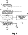
- method 200 continues to block 308 to determine whether the TCM 104 can assist the brake controller 142 with controlling vehicle braking and speed. If the TCM 104 is unable to communicate with the brake controller 142, a determination is made in block 702 ( Fig. 7 ) that the brake controller 142 controls vehicle braking. In this embodiment, the TCM 104 is unable to control vehicle speed and the method 200 is disabled in block 704.
- a transfer case 148 is provided with a transfer case controller 152.
- the transfer case 148 and transfer case controller 152 are coupled by a harness or wire 150.
- the transfer case controller 152 is also electrically coupled to the TCM 104 by a harness or wire (not shown).
- Transfer cases are known in the art as part of a four wheel drive system or all-wheel drive system.
- the transfer case can be connected to the transmission and to the front and rear axles via drive shafts.
- the transfer case receives power from the transmission and transmits the received power to the front and rear axles.
- transfer cases There are many types of transfer cases available, and for purposes of the present disclosure, any transfer case that couples to an automatic transmission output shaft can be used.
- the method 200 can proceed to block 602 in Fig. 6 .
- the transfer case 148 presumably includes a separate and independent controller 152 that can communicate with the TCM 104.
- the transfer case controller 152 can control the transfer case 148 into a neutral state. While it is possible that the transfer case 148 can be controlled to neutral, this is not always advantageous because the TCM 104 is unable to control the vehicle speed in this condition. Rather, in this condition, the amount of power is reduced or relieved that is directed to the vehicle tires. If the vehicle is moving when the transfer case 148 shifts to neutral, the momentum of the vehicle is not instantaneously stopped. Thus, when an object is in the path of the moving vehicle, shifting the transfer case 148 to neutral may not prevent the vehicle from contacting the object.
- the method 200 continues to block 502 where the transmission gear ratio is calculated (see Fig. 5 ).
- the gear ratio is determined by the ratio of the input speed to output speed or turbine speed to output speed.
- the input speed sensor 126 can measure the transmission input speed and the output speed sensor 130 can measure the transmission output speed. The measured input and output speeds can be transmitted to the TCM 104, which can then calculate the gear ratio based on the two measurements.
- the method 200 proceeds to block 504 to determine whether the TCM 104 is capable of limiting engine speed or torque.
- the TCM 104 can communicate with an engine controller ("ECM").
- ECM engine controller
- the TCM 104 can send commands or instructions to the ECM to control the engine output (i.e., speed or torque).
- the TCM 104 can limit engine torque by requesting a lower engine speed (e.g., 600 RPM) or torque (e.g., -3000 Nm) until a certain condition is met.
- a torque limit in certain transmission ranges i.e., gear ratios).
- the TCM 104 can request less engine speed or torque from the engine to help reduce the vehicle speed so that the vehicle avoids contacting the object. To do so, in block 506, the TCM 104 can send commands or instructions to the ECM to reduce engine speed or torque, which will effectively reduce transmission output as well. This can also be achieved by filling an impeding clutch and trimming an applied clutch in block 508, as described in further detail below.
- a transmission 102 can include several "gears" or “ranges” which are determined based on the ratio of the input to the output of the transmission. To achieve a certain range, one or more clutches are applied.
- a transmission can shift into another range by unapplying (i.e., trimming) one of the applied clutches and applying (i.e., filling) an unapplied clutch.
- the timing of filling the unapplied clutch with transmission fluid and trimming the applied clutch is controlled by the TCM 104.
- a properly controlled "fill and trim" cycle can enable the transmission to smoothly shift between ranges.
- the TCM 104 can control which clutches are applied and unapplied.
- the output of the transmission can be locked or reduced when a third clutch is quickly applied.
- applying a third clutch e.g., bringing the clutch fully on
- the clutch pressure in one of the two applied clutches is at least partially trimmed and the clutch pressure in one of the unapplied clutches is at least partially filled (hence, a third clutch is at least partially applied).
- only one of the three applied clutches is at full pressure, whereas the other two clutches are at a partial or limited pressure. While this can lock the transmission output by not allowing the output shaft to rotate, the reduced clutch pressures can also reduce the amount of torque passing through the transmission.
- the normally-unapplied clutch i.e., third clutch
- the normally-unapplied clutch that is at least partially filled can be referred to as an impeding clutch.
- the timing, T 1 , of block 508 is important.
- the filling and trimming of the impeding clutch can be completed within about 2 seconds.
- the third clutch can begin impeding within about 1 second.
- block 508 can be completed within a few seconds. Since the amount of time for block 508 to be completed is quick, the transmission output can be stopped or substantially reduced such that the vehicle can either be stopped or its speed reduced substantially. Unseen objects that are in the path of the moving vehicle can be avoided by filling an impeding clutch in block 508.
- method 200 proceeds to block 802.
- the TCM 104 determines if it can communicate with the brake controller 142, but the TCM 104 also determines whether the brake controller 142 can accept instructions or requests therefrom. If the brake controller 142 does accept requests from the TCM 104, in block 804, the TCM 104 determines if the brake controller 142 accepts requests for deceleration rates.
- the TCM 104 can control vehicle braking by communicating deceleration rates to the brake controller 142 based on vehicle speed, distance, and current vehicle acceleration.
- the distance is determined by the proximity sensor and communicated to the TCM 104.
- the TCM 104 can compute vehicle speed and acceleration or receive the data from the ECM.
- the vehicle speed can be controlled by the TCM 104 and brake controller 142.
- deceleration requests can be determined based on Proportional-Integral-Derivative (PID) control.
- PID Proportional-Integral-Derivative
- the TCM 104 can compute vehicle speed. If the vehicle speed is low, e.g., 10 mph, the TCM 104 can request a proportionally low deceleration rate to the brake controller 142. Alternatively, if the vehicle speed is high, e.g., 20 mph, the TCM 104 can request a proportionally higher deceleration rate to the brake controller 142. In turn, the brake controller 142 receives the deceleration rate request and adjusts the braking force or pressure on the vehicle tires.
- PID Proportional-Integral-Derivative
- the TCM 104 determines that vehicle speed is changing, the TCM 104 is capable of differentially controlling the deceleration rate requests. For instance, if the vehicle speed is decreasing rapidly, the TCM 104 can reduce the clutch pressure of the impeding clutch. Likewise, if the vehicle speed is increasing rapidly, the TCM 104 can increase the clutch pressure of the impeding clutch. In addition, the TCM 104 may continue to incrementally increase the deceleration rate if there is no other way in which the vehicle is brought to a stopped position. This integral control allows the vehicle to be stopped when the vehicle is moving slowly.
- PID control is only one exemplary way in which deceleration rate requests can be communicated from the TCM 104 to the brake controller 142 and/or transmission 102. There are other ways that one skilled in the art could communicate deceleration rates to the brake controller 142 and/or transmission 102.
- step 804 if the brake controller 142 does not accept deceleration requests from the TCM 104, method 200 proceeds to block 810.
- block 810 a determination is made whether the brake controller 142 accepts requests regarding torque or pressure levels from the TCM 104. In the event the brake controller 142 does not accept torque or pressure level requests from the TCM 104, method 200 continues to block 808 to determine whether the TCM 104 can communicate with the brake controller 142 by another means. If it is determined that the brake controller 142 cannot communicate with or accept instructions from the TCM 104, then method 200 returns to step 702 ( Fig. 7 ) and the brake controller 142 controls vehicle braking without receiving input from the TCM 104.
- the brake controller 142 may be able to accept brake torque and/or pressure requests from the TCM 104.
- method 200 proceeds to block 812.
- the TCM 104 receives input signals from the proximity sensor and calculates vehicle speed and acceleration (or, alternatively, receives the data from another source such as the ECM). Based on the current input signal, vehicle speed, and vehicle acceleration, the TCM 104 communicates brake torque or pressure levels to the brake controller 142 to control vehicle braking.
- the vehicle speed can be controlled so that unseen objects and the like can be avoided by a moving vehicle.
- the conditions set forth in blocks 202, 204, 206, and 208 are constantly being monitored by the TCM 104. If one of these conditions is suddenly not met, method 200 terminates and is disabled until all of the conditions are satisfied. For example, if the driver suddenly presses the accelerator pedal and the throttle exceeds the value of "Thresh1," the TCM 104 determines that the method 200 is no longer desired and is therefore disabled.
- method 200 is one of many programs or routines that the TCM 104 performs.
- TCM 104 continues to test the conditions set forth in blocks 202, 204, 206, and 208, but the TCM 104 also performs other programs or routines.
- the TCM 104 when the TCM 104 is able to limit engine speed or engine torque in block 504 ( Fig. 5 ), it may also be able to request to the ECM to shut off the engine (i.e., shut off the ignition). While this may be less preferable and only used under emergency conditions, it is another possible communication or request that the TCM 104 can make to the ECM when controlling vehicle braking.
Landscapes
- Engineering & Computer Science (AREA)
- Chemical & Material Sciences (AREA)
- Combustion & Propulsion (AREA)
- Transportation (AREA)
- Mechanical Engineering (AREA)
- Automation & Control Theory (AREA)
- Control Of Transmission Device (AREA)
Applications Claiming Priority (2)
| Application Number | Priority Date | Filing Date | Title |
|---|---|---|---|
| US12/833,172 US9403532B2 (en) | 2010-07-09 | 2010-07-09 | Closed-loop transmission integration with forward and/or reverse assist system |
| PCT/US2011/042301 WO2012006140A2 (en) | 2010-07-09 | 2011-06-29 | Closed-loop transmission integration with forward and/or reverse assist system |
Publications (3)
| Publication Number | Publication Date |
|---|---|
| EP2591252A2 EP2591252A2 (en) | 2013-05-15 |
| EP2591252A4 EP2591252A4 (en) | 2018-04-25 |
| EP2591252B1 true EP2591252B1 (en) | 2020-11-25 |
Family
ID=45439172
Family Applications (1)
| Application Number | Title | Priority Date | Filing Date |
|---|---|---|---|
| EP11804168.0A Active EP2591252B1 (en) | 2010-07-09 | 2011-06-29 | Closed-loop transmission integration with forward and/or reverse assist system |
Country Status (7)
| Country | Link |
|---|---|
| US (1) | US9403532B2 (zh) |
| EP (1) | EP2591252B1 (zh) |
| KR (1) | KR20130091330A (zh) |
| CN (1) | CN103069197B (zh) |
| AU (1) | AU2011276519B2 (zh) |
| CA (1) | CA2804485C (zh) |
| WO (1) | WO2012006140A2 (zh) |
Families Citing this family (5)
| Publication number | Priority date | Publication date | Assignee | Title |
|---|---|---|---|---|
| DE102009013398B4 (de) * | 2009-03-16 | 2018-04-19 | Dr. Ing. H.C. F. Porsche Aktiengesellschaft | Verfahren zur Unterbrechung des Kraftflusses im Antriebsstrang eines Fahrzeuges im Crashfall |
| US8862350B2 (en) * | 2012-08-07 | 2014-10-14 | GM Global Technology Operations LLC | Method and apparatus for controlling a multi-mode powertrain system |
| US9047780B2 (en) | 2012-11-16 | 2015-06-02 | Robert Bosch Gmbh | Collision mitigation systems and methods using driver attentiveness |
| US10093304B2 (en) * | 2015-09-11 | 2018-10-09 | Ford Global Technologies, Llc | Enhanced electric drive mode having predicted destinations to reduce engine starts |
| CN114670816B (zh) * | 2021-04-08 | 2024-08-23 | 北京新能源汽车股份有限公司 | 一种倒车控制方法、装置及电动汽车 |
Family Cites Families (39)
| Publication number | Priority date | Publication date | Assignee | Title |
|---|---|---|---|---|
| JPS60163732A (ja) * | 1984-02-03 | 1985-08-26 | Nissan Motor Co Ltd | 車間距離制御装置 |
| JPH02212231A (ja) | 1989-02-10 | 1990-08-23 | Mazda Motor Corp | 自動変速機の制御装置 |
| US5035158A (en) | 1989-09-25 | 1991-07-30 | Automotive Products (Usa) Inc. | Electric shift and transfer case apparatus with control system therefore |
| DE4418085C2 (de) * | 1993-05-21 | 1999-09-09 | Toyota Motor Co Ltd | Sicherheitseinrichtung für ein Fahrzeug |
| JPH0747864A (ja) * | 1993-06-15 | 1995-02-21 | Nissan Motor Co Ltd | 車間距離制御装置 |
| JP3291859B2 (ja) * | 1993-08-31 | 2002-06-17 | 三菱自動車工業株式会社 | 自動車の走行制御装置 |
| US6067495A (en) * | 1997-06-24 | 2000-05-23 | Chrysler Corporation | Acceleration based shift strategy for an automatic transmission |
| JP3661495B2 (ja) * | 1998-08-26 | 2005-06-15 | 日産自動車株式会社 | 先行車追従制御装置 |
| DE10014328A1 (de) * | 1999-03-26 | 2000-09-28 | Denso Corp | Automatische Fahrregelvorrichtung |
| JP3620359B2 (ja) * | 1999-08-10 | 2005-02-16 | 日産自動車株式会社 | 車両用走行制御装置 |
| JP2001146121A (ja) * | 1999-11-19 | 2001-05-29 | Toyota Motor Corp | 変速機付きハイブリッド車両の制御装置 |
| JP4254027B2 (ja) * | 2000-07-26 | 2009-04-15 | 株式会社デンソー | 車両統合制御システム |
| JP3911979B2 (ja) * | 2000-08-29 | 2007-05-09 | トヨタ自動車株式会社 | 警報装置およびその警報装置を備えた走行制御装置 |
| US7277782B2 (en) * | 2001-01-31 | 2007-10-02 | Oshkosh Truck Corporation | Control system and method for electric vehicle |
| JP4045961B2 (ja) * | 2003-01-24 | 2008-02-13 | 日産自動車株式会社 | 制動制御装置 |
| WO2005061875A1 (de) * | 2003-12-20 | 2005-07-07 | Robert Bosch Gmbh | Verfahren und vorrichtung zum betreiben einer antriebseinheit eines fahrzeugs im schbbetrieb |
| JP4175291B2 (ja) * | 2004-05-12 | 2008-11-05 | トヨタ自動車株式会社 | 車両の減速制御装置 |
| US8423254B2 (en) * | 2004-11-29 | 2013-04-16 | Hitachi, Ltd. | Control device for automobile |
| US7263824B2 (en) * | 2004-12-03 | 2007-09-04 | Cummins, Inc. | Exhaust gas aftertreatment device for an internal combustion engine |
| KR20060067172A (ko) * | 2004-12-14 | 2006-06-19 | 현대자동차주식회사 | 차량의 충돌 방지장치 및 그 방법 |
| JP4424213B2 (ja) * | 2005-01-26 | 2010-03-03 | トヨタ自動車株式会社 | 車両の制御装置 |
| JP4466571B2 (ja) * | 2005-05-12 | 2010-05-26 | 株式会社デンソー | ドライバ状態検出装置、車載警報装置、運転支援システム |
| JP4674491B2 (ja) * | 2005-05-20 | 2011-04-20 | 日産自動車株式会社 | 先行車追従制御装置 |
| CN2848655Y (zh) * | 2005-07-02 | 2006-12-20 | 甘淼漾 | 汽车遇险自动减速、停车装置 |
| DE102005042347B4 (de) | 2005-09-07 | 2024-06-06 | Zf Friedrichshafen Ag | Automatisches oder automatisiertes Kraftfahrzeug-Getriebe und Verfahren zur Steuerung dessen, mit einem Notfahrbetrieb und einem Normalfahrbetrieb |
| JP4871687B2 (ja) * | 2005-10-03 | 2012-02-08 | 日立オートモティブシステムズ株式会社 | 車両制御システム |
| US8046146B2 (en) * | 2006-02-03 | 2011-10-25 | Kelsey-Hayes Company | Adaptive ABS control |
| US7611414B2 (en) * | 2006-02-13 | 2009-11-03 | Magna Powertrain Usa, Inc. | Torque limiting clutches for power transfer units |
| US7389176B2 (en) | 2006-06-08 | 2008-06-17 | Nissan Motor Co., Ltd. | Engine output control apparatus of power train |
| US7517298B2 (en) * | 2006-09-05 | 2009-04-14 | Ford Global Technologies, Llc | Power-on downshift control for a hybrid electric vehicle powertrain |
| US7719410B2 (en) * | 2007-01-08 | 2010-05-18 | Gm Global Technology Operations, Inc. | Threat assessment state processing for collision warning, mitigation and/or avoidance in ground-based vehicles |
| US7957873B2 (en) * | 2007-03-09 | 2011-06-07 | GM Global Technology Operations LLC | Vehicle transmission shift inhibit method and apparatus |
| DE102007047363A1 (de) * | 2007-10-02 | 2009-04-09 | Volkswagen Ag | Verfahren zur Steuerung eines automatischen, insbesondere automatisierten Getriebes eines Kraftfahrzeugs, vzw. eines Doppelkupplungsgetriebes |
| US8224539B2 (en) * | 2007-11-02 | 2012-07-17 | GM Global Technology Operations LLC | Method for altitude-compensated transmission shift scheduling |
| US8090517B2 (en) * | 2007-12-19 | 2012-01-03 | Nissan Motor Co., Ltd. | Inter-vehicle distance maintenance supporting system and method |
| JP2010221995A (ja) * | 2009-02-27 | 2010-10-07 | Nissan Motor Co Ltd | 車両用運転操作補助装置、車両用運転操作補助方法および自動車 |
| US8694218B2 (en) * | 2009-03-24 | 2014-04-08 | Allison Transmission, Inc. | Acceleration based mode switch |
| BRPI1009667A2 (pt) * | 2009-06-11 | 2016-03-15 | Eaton Corp | método de detecção para detectar um vazamento de cilindro em um sistema de bomba, método de detecção para detectar um vazamento de gás em um sistema de bomba, método de detecção * para detectar um vazamento de óleo em um sistema de bomba, método limite para limitar a velocidade de um motor de um veículo e sistema de bomba de fluído |
| US8255134B2 (en) * | 2009-10-19 | 2012-08-28 | GM Global Technology Operations LLC | Adaptive cruise control downshift request systems for manual transmission vehicles |
-
2010
- 2010-07-09 US US12/833,172 patent/US9403532B2/en active Active
-
2011
- 2011-06-29 WO PCT/US2011/042301 patent/WO2012006140A2/en active Application Filing
- 2011-06-29 CN CN201180039037.XA patent/CN103069197B/zh active Active
- 2011-06-29 KR KR1020137003289A patent/KR20130091330A/ko not_active Application Discontinuation
- 2011-06-29 AU AU2011276519A patent/AU2011276519B2/en active Active
- 2011-06-29 CA CA2804485A patent/CA2804485C/en active Active
- 2011-06-29 EP EP11804168.0A patent/EP2591252B1/en active Active
Non-Patent Citations (1)
| Title |
|---|
| None * |
Also Published As
| Publication number | Publication date |
|---|---|
| CA2804485A1 (en) | 2012-01-12 |
| EP2591252A2 (en) | 2013-05-15 |
| CA2804485C (en) | 2016-08-09 |
| CN103069197B (zh) | 2016-02-10 |
| WO2012006140A2 (en) | 2012-01-12 |
| WO2012006140A3 (en) | 2012-04-26 |
| AU2011276519A1 (en) | 2013-02-07 |
| AU2011276519B2 (en) | 2014-02-20 |
| CN103069197A (zh) | 2013-04-24 |
| US20120010791A1 (en) | 2012-01-12 |
| US9403532B2 (en) | 2016-08-02 |
| KR20130091330A (ko) | 2013-08-16 |
| EP2591252A4 (en) | 2018-04-25 |
Similar Documents
| Publication | Publication Date | Title |
|---|---|---|
| KR101994525B1 (ko) | 차량 주행 제어 장치 | |
| KR101939441B1 (ko) | 차량의 브레이크 제어 장치 | |
| EP2591252B1 (en) | Closed-loop transmission integration with forward and/or reverse assist system | |
| US10421456B2 (en) | Customized electric parking brake response to maintain engine auto-stop with brake released | |
| US20170203759A1 (en) | Vehicle control in traffic conditions | |
| JP3871728B2 (ja) | 標準的なエンジン制御モードを用いてのインテリジェントな走行制御のためのシステム及び方法 | |
| RU2696891C2 (ru) | Адаптивное устройство автоматического регулирования скорости движения во время буксировки | |
| US9688279B2 (en) | Vehicle traction control method, system, controller and vehicle with such a system | |
| US10501080B2 (en) | Electric parking brake usage for vehicle powertrain out of operation conditions | |
| EP3459820B1 (en) | Driving support device | |
| MX2012014069A (es) | Control regulador electronico. | |
| US10583838B2 (en) | Systems and methods of automatic braking for manual transmissions | |
| US20180001898A1 (en) | Vehicle control apparatus | |
| US20130073157A1 (en) | Enhanced torque model for vehicle having a cvt | |
| EP1939060B1 (en) | Control device for vehicle | |
| JP6549958B2 (ja) | 自動運転装置 | |
| US11932225B1 (en) | Trailer brake control system | |
| JP7256475B2 (ja) | 車両走行制御装置 | |
| US20230129531A1 (en) | Erroneous start suppression device for a vehicle | |
| US12122339B2 (en) | Collision avoidance support device for a vehicle and collision avoidance support program for a vehicle | |
| JP2006123631A (ja) | 車両の制御装置 | |
| US20230061982A1 (en) | Collision avoidance support device for a vehicle and collision avoidance support program for a vehicle | |
| KR102365179B1 (ko) | Tmed 차량의 변속기 제어 방법 | |
| JP2006076427A (ja) | 電動駐車ブレーキ装置 | |
| JP2023128249A (ja) | 車両制御システム |
Legal Events
| Date | Code | Title | Description |
|---|---|---|---|
| PUAI | Public reference made under article 153(3) epc to a published international application that has entered the european phase |
Free format text: ORIGINAL CODE: 0009012 |
|
| 17P | Request for examination filed |
Effective date: 20130205 |
|
| AK | Designated contracting states |
Kind code of ref document: A2 Designated state(s): AL AT BE BG CH CY CZ DE DK EE ES FI FR GB GR HR HU IE IS IT LI LT LU LV MC MK MT NL NO PL PT RO RS SE SI SK SM TR |
|
| DAX | Request for extension of the european patent (deleted) | ||
| A4 | Supplementary search report drawn up and despatched |
Effective date: 20180322 |
|
| RIC1 | Information provided on ipc code assigned before grant |
Ipc: F16H 61/02 20060101AFI20180316BHEP Ipc: B60W 10/18 20120101ALI20180316BHEP Ipc: B60W 50/00 20060101ALN20180316BHEP Ipc: B60W 30/09 20120101ALI20180316BHEP Ipc: F16H 59/44 20060101ALI20180316BHEP |
|
| STAA | Information on the status of an ep patent application or granted ep patent |
Free format text: STATUS: EXAMINATION IS IN PROGRESS |
|
| 17Q | First examination report despatched |
Effective date: 20190521 |
|
| RIC1 | Information provided on ipc code assigned before grant |
Ipc: F16H 59/44 20060101ALI20200520BHEP Ipc: B60W 30/09 20120101ALI20200520BHEP Ipc: B60W 10/18 20120101ALI20200520BHEP Ipc: B60W 50/00 20060101ALN20200520BHEP Ipc: F16H 61/02 20060101AFI20200520BHEP |
|
| GRAP | Despatch of communication of intention to grant a patent |
Free format text: ORIGINAL CODE: EPIDOSNIGR1 |
|
| STAA | Information on the status of an ep patent application or granted ep patent |
Free format text: STATUS: GRANT OF PATENT IS INTENDED |
|
| INTG | Intention to grant announced |
Effective date: 20200706 |
|
| GRAS | Grant fee paid |
Free format text: ORIGINAL CODE: EPIDOSNIGR3 |
|
| GRAA | (expected) grant |
Free format text: ORIGINAL CODE: 0009210 |
|
| STAA | Information on the status of an ep patent application or granted ep patent |
Free format text: STATUS: THE PATENT HAS BEEN GRANTED |
|
| AK | Designated contracting states |
Kind code of ref document: B1 Designated state(s): AL AT BE BG CH CY CZ DE DK EE ES FI FR GB GR HR HU IE IS IT LI LT LU LV MC MK MT NL NO PL PT RO RS SE SI SK SM TR |
|
| REG | Reference to a national code |
Ref country code: GB Ref legal event code: FG4D |
|
| REG | Reference to a national code |
Ref country code: CH Ref legal event code: EP |
|
| REG | Reference to a national code |
Ref country code: AT Ref legal event code: REF Ref document number: 1338715 Country of ref document: AT Kind code of ref document: T Effective date: 20201215 |
|
| REG | Reference to a national code |
Ref country code: DE Ref legal event code: R096 Ref document number: 602011069436 Country of ref document: DE |
|
| REG | Reference to a national code |
Ref country code: IE Ref legal event code: FG4D |
|
| REG | Reference to a national code |
Ref country code: AT Ref legal event code: MK05 Ref document number: 1338715 Country of ref document: AT Kind code of ref document: T Effective date: 20201125 |
|
| REG | Reference to a national code |
Ref country code: NL Ref legal event code: MP Effective date: 20201125 |
|
| PG25 | Lapsed in a contracting state [announced via postgrant information from national office to epo] |
Ref country code: GR Free format text: LAPSE BECAUSE OF FAILURE TO SUBMIT A TRANSLATION OF THE DESCRIPTION OR TO PAY THE FEE WITHIN THE PRESCRIBED TIME-LIMIT Effective date: 20210226 Ref country code: FI Free format text: LAPSE BECAUSE OF FAILURE TO SUBMIT A TRANSLATION OF THE DESCRIPTION OR TO PAY THE FEE WITHIN THE PRESCRIBED TIME-LIMIT Effective date: 20201125 Ref country code: RS Free format text: LAPSE BECAUSE OF FAILURE TO SUBMIT A TRANSLATION OF THE DESCRIPTION OR TO PAY THE FEE WITHIN THE PRESCRIBED TIME-LIMIT Effective date: 20201125 Ref country code: PT Free format text: LAPSE BECAUSE OF FAILURE TO SUBMIT A TRANSLATION OF THE DESCRIPTION OR TO PAY THE FEE WITHIN THE PRESCRIBED TIME-LIMIT Effective date: 20210325 Ref country code: NO Free format text: LAPSE BECAUSE OF FAILURE TO SUBMIT A TRANSLATION OF THE DESCRIPTION OR TO PAY THE FEE WITHIN THE PRESCRIBED TIME-LIMIT Effective date: 20210225 |
|
| PG25 | Lapsed in a contracting state [announced via postgrant information from national office to epo] |
Ref country code: LV Free format text: LAPSE BECAUSE OF FAILURE TO SUBMIT A TRANSLATION OF THE DESCRIPTION OR TO PAY THE FEE WITHIN THE PRESCRIBED TIME-LIMIT Effective date: 20201125 Ref country code: PL Free format text: LAPSE BECAUSE OF FAILURE TO SUBMIT A TRANSLATION OF THE DESCRIPTION OR TO PAY THE FEE WITHIN THE PRESCRIBED TIME-LIMIT Effective date: 20201125 Ref country code: SE Free format text: LAPSE BECAUSE OF FAILURE TO SUBMIT A TRANSLATION OF THE DESCRIPTION OR TO PAY THE FEE WITHIN THE PRESCRIBED TIME-LIMIT Effective date: 20201125 Ref country code: AT Free format text: LAPSE BECAUSE OF FAILURE TO SUBMIT A TRANSLATION OF THE DESCRIPTION OR TO PAY THE FEE WITHIN THE PRESCRIBED TIME-LIMIT Effective date: 20201125 Ref country code: BG Free format text: LAPSE BECAUSE OF FAILURE TO SUBMIT A TRANSLATION OF THE DESCRIPTION OR TO PAY THE FEE WITHIN THE PRESCRIBED TIME-LIMIT Effective date: 20210225 Ref country code: IS Free format text: LAPSE BECAUSE OF FAILURE TO SUBMIT A TRANSLATION OF THE DESCRIPTION OR TO PAY THE FEE WITHIN THE PRESCRIBED TIME-LIMIT Effective date: 20210325 |
|
| REG | Reference to a national code |
Ref country code: LT Ref legal event code: MG9D |
|
| PG25 | Lapsed in a contracting state [announced via postgrant information from national office to epo] |
Ref country code: HR Free format text: LAPSE BECAUSE OF FAILURE TO SUBMIT A TRANSLATION OF THE DESCRIPTION OR TO PAY THE FEE WITHIN THE PRESCRIBED TIME-LIMIT Effective date: 20201125 |
|
| PG25 | Lapsed in a contracting state [announced via postgrant information from national office to epo] |
Ref country code: CZ Free format text: LAPSE BECAUSE OF FAILURE TO SUBMIT A TRANSLATION OF THE DESCRIPTION OR TO PAY THE FEE WITHIN THE PRESCRIBED TIME-LIMIT Effective date: 20201125 Ref country code: EE Free format text: LAPSE BECAUSE OF FAILURE TO SUBMIT A TRANSLATION OF THE DESCRIPTION OR TO PAY THE FEE WITHIN THE PRESCRIBED TIME-LIMIT Effective date: 20201125 Ref country code: SM Free format text: LAPSE BECAUSE OF FAILURE TO SUBMIT A TRANSLATION OF THE DESCRIPTION OR TO PAY THE FEE WITHIN THE PRESCRIBED TIME-LIMIT Effective date: 20201125 Ref country code: LT Free format text: LAPSE BECAUSE OF FAILURE TO SUBMIT A TRANSLATION OF THE DESCRIPTION OR TO PAY THE FEE WITHIN THE PRESCRIBED TIME-LIMIT Effective date: 20201125 Ref country code: SK Free format text: LAPSE BECAUSE OF FAILURE TO SUBMIT A TRANSLATION OF THE DESCRIPTION OR TO PAY THE FEE WITHIN THE PRESCRIBED TIME-LIMIT Effective date: 20201125 Ref country code: RO Free format text: LAPSE BECAUSE OF FAILURE TO SUBMIT A TRANSLATION OF THE DESCRIPTION OR TO PAY THE FEE WITHIN THE PRESCRIBED TIME-LIMIT Effective date: 20201125 |
|
| REG | Reference to a national code |
Ref country code: DE Ref legal event code: R097 Ref document number: 602011069436 Country of ref document: DE |
|
| PG25 | Lapsed in a contracting state [announced via postgrant information from national office to epo] |
Ref country code: DK Free format text: LAPSE BECAUSE OF FAILURE TO SUBMIT A TRANSLATION OF THE DESCRIPTION OR TO PAY THE FEE WITHIN THE PRESCRIBED TIME-LIMIT Effective date: 20201125 |
|
| PLBE | No opposition filed within time limit |
Free format text: ORIGINAL CODE: 0009261 |
|
| STAA | Information on the status of an ep patent application or granted ep patent |
Free format text: STATUS: NO OPPOSITION FILED WITHIN TIME LIMIT |
|
| PG25 | Lapsed in a contracting state [announced via postgrant information from national office to epo] |
Ref country code: NL Free format text: LAPSE BECAUSE OF FAILURE TO SUBMIT A TRANSLATION OF THE DESCRIPTION OR TO PAY THE FEE WITHIN THE PRESCRIBED TIME-LIMIT Effective date: 20201125 Ref country code: AL Free format text: LAPSE BECAUSE OF FAILURE TO SUBMIT A TRANSLATION OF THE DESCRIPTION OR TO PAY THE FEE WITHIN THE PRESCRIBED TIME-LIMIT Effective date: 20201125 Ref country code: IT Free format text: LAPSE BECAUSE OF FAILURE TO SUBMIT A TRANSLATION OF THE DESCRIPTION OR TO PAY THE FEE WITHIN THE PRESCRIBED TIME-LIMIT Effective date: 20201125 |
|
| 26N | No opposition filed |
Effective date: 20210826 |
|
| PG25 | Lapsed in a contracting state [announced via postgrant information from national office to epo] |
Ref country code: ES Free format text: LAPSE BECAUSE OF FAILURE TO SUBMIT A TRANSLATION OF THE DESCRIPTION OR TO PAY THE FEE WITHIN THE PRESCRIBED TIME-LIMIT Effective date: 20201125 Ref country code: SI Free format text: LAPSE BECAUSE OF FAILURE TO SUBMIT A TRANSLATION OF THE DESCRIPTION OR TO PAY THE FEE WITHIN THE PRESCRIBED TIME-LIMIT Effective date: 20201125 |
|
| PG25 | Lapsed in a contracting state [announced via postgrant information from national office to epo] |
Ref country code: MC Free format text: LAPSE BECAUSE OF FAILURE TO SUBMIT A TRANSLATION OF THE DESCRIPTION OR TO PAY THE FEE WITHIN THE PRESCRIBED TIME-LIMIT Effective date: 20201125 |
|
| REG | Reference to a national code |
Ref country code: CH Ref legal event code: PL |
|
| GBPC | Gb: european patent ceased through non-payment of renewal fee |
Effective date: 20210629 |
|
| REG | Reference to a national code |
Ref country code: BE Ref legal event code: MM Effective date: 20210630 |
|
| PG25 | Lapsed in a contracting state [announced via postgrant information from national office to epo] |
Ref country code: LU Free format text: LAPSE BECAUSE OF NON-PAYMENT OF DUE FEES Effective date: 20210629 |
|
| PG25 | Lapsed in a contracting state [announced via postgrant information from national office to epo] |
Ref country code: LI Free format text: LAPSE BECAUSE OF NON-PAYMENT OF DUE FEES Effective date: 20210630 Ref country code: IE Free format text: LAPSE BECAUSE OF NON-PAYMENT OF DUE FEES Effective date: 20210629 Ref country code: GB Free format text: LAPSE BECAUSE OF NON-PAYMENT OF DUE FEES Effective date: 20210629 Ref country code: CH Free format text: LAPSE BECAUSE OF NON-PAYMENT OF DUE FEES Effective date: 20210630 |
|
| PG25 | Lapsed in a contracting state [announced via postgrant information from national office to epo] |
Ref country code: IS Free format text: LAPSE BECAUSE OF FAILURE TO SUBMIT A TRANSLATION OF THE DESCRIPTION OR TO PAY THE FEE WITHIN THE PRESCRIBED TIME-LIMIT Effective date: 20210325 Ref country code: FR Free format text: LAPSE BECAUSE OF NON-PAYMENT OF DUE FEES Effective date: 20210630 |
|
| PG25 | Lapsed in a contracting state [announced via postgrant information from national office to epo] |
Ref country code: BE Free format text: LAPSE BECAUSE OF NON-PAYMENT OF DUE FEES Effective date: 20210630 |
|
| PG25 | Lapsed in a contracting state [announced via postgrant information from national office to epo] |
Ref country code: HU Free format text: LAPSE BECAUSE OF FAILURE TO SUBMIT A TRANSLATION OF THE DESCRIPTION OR TO PAY THE FEE WITHIN THE PRESCRIBED TIME-LIMIT; INVALID AB INITIO Effective date: 20110629 Ref country code: CY Free format text: LAPSE BECAUSE OF FAILURE TO SUBMIT A TRANSLATION OF THE DESCRIPTION OR TO PAY THE FEE WITHIN THE PRESCRIBED TIME-LIMIT Effective date: 20201125 |
|
| P01 | Opt-out of the competence of the unified patent court (upc) registered |
Effective date: 20230521 |
|
| PG25 | Lapsed in a contracting state [announced via postgrant information from national office to epo] |
Ref country code: MK Free format text: LAPSE BECAUSE OF FAILURE TO SUBMIT A TRANSLATION OF THE DESCRIPTION OR TO PAY THE FEE WITHIN THE PRESCRIBED TIME-LIMIT Effective date: 20201125 |
|
| PG25 | Lapsed in a contracting state [announced via postgrant information from national office to epo] |
Ref country code: TR Free format text: LAPSE BECAUSE OF FAILURE TO SUBMIT A TRANSLATION OF THE DESCRIPTION OR TO PAY THE FEE WITHIN THE PRESCRIBED TIME-LIMIT Effective date: 20201125 |
|
| PGFP | Annual fee paid to national office [announced via postgrant information from national office to epo] |
Ref country code: DE Payment date: 20240627 Year of fee payment: 14 |
|
| PG25 | Lapsed in a contracting state [announced via postgrant information from national office to epo] |
Ref country code: MT Free format text: LAPSE BECAUSE OF FAILURE TO SUBMIT A TRANSLATION OF THE DESCRIPTION OR TO PAY THE FEE WITHIN THE PRESCRIBED TIME-LIMIT Effective date: 20201125 |