EP2587035B1 - Heat retention member for cylinder bore wall, internal combustion engine, and automobile - Google Patents
Heat retention member for cylinder bore wall, internal combustion engine, and automobile Download PDFInfo
- Publication number
- EP2587035B1 EP2587035B1 EP11797982.3A EP11797982A EP2587035B1 EP 2587035 B1 EP2587035 B1 EP 2587035B1 EP 11797982 A EP11797982 A EP 11797982A EP 2587035 B1 EP2587035 B1 EP 2587035B1
- Authority
- EP
- European Patent Office
- Prior art keywords
- cylinder bore
- bore wall
- insulating member
- internal combustion
- combustion engine
- Prior art date
- Legal status (The legal status is an assumption and is not a legal conclusion. Google has not performed a legal analysis and makes no representation as to the accuracy of the status listed.)
- Active
Links
Images


Classifications
-
- F—MECHANICAL ENGINEERING; LIGHTING; HEATING; WEAPONS; BLASTING
- F02—COMBUSTION ENGINES; HOT-GAS OR COMBUSTION-PRODUCT ENGINE PLANTS
- F02F—CYLINDERS, PISTONS OR CASINGS, FOR COMBUSTION ENGINES; ARRANGEMENTS OF SEALINGS IN COMBUSTION ENGINES
- F02F1/00—Cylinders; Cylinder heads
- F02F1/02—Cylinders; Cylinder heads having cooling means
- F02F1/10—Cylinders; Cylinder heads having cooling means for liquid cooling
- F02F1/16—Cylinder liners of wet type
-
- F—MECHANICAL ENGINEERING; LIGHTING; HEATING; WEAPONS; BLASTING
- F01—MACHINES OR ENGINES IN GENERAL; ENGINE PLANTS IN GENERAL; STEAM ENGINES
- F01P—COOLING OF MACHINES OR ENGINES IN GENERAL; COOLING OF INTERNAL-COMBUSTION ENGINES
- F01P3/00—Liquid cooling
- F01P3/02—Arrangements for cooling cylinders or cylinder heads
-
- F—MECHANICAL ENGINEERING; LIGHTING; HEATING; WEAPONS; BLASTING
- F02—COMBUSTION ENGINES; HOT-GAS OR COMBUSTION-PRODUCT ENGINE PLANTS
- F02F—CYLINDERS, PISTONS OR CASINGS, FOR COMBUSTION ENGINES; ARRANGEMENTS OF SEALINGS IN COMBUSTION ENGINES
- F02F1/00—Cylinders; Cylinder heads
- F02F1/02—Cylinders; Cylinder heads having cooling means
- F02F1/10—Cylinders; Cylinder heads having cooling means for liquid cooling
- F02F1/14—Cylinders with means for directing, guiding or distributing liquid stream
-
- F—MECHANICAL ENGINEERING; LIGHTING; HEATING; WEAPONS; BLASTING
- F01—MACHINES OR ENGINES IN GENERAL; ENGINE PLANTS IN GENERAL; STEAM ENGINES
- F01P—COOLING OF MACHINES OR ENGINES IN GENERAL; COOLING OF INTERNAL-COMBUSTION ENGINES
- F01P3/00—Liquid cooling
- F01P3/02—Arrangements for cooling cylinders or cylinder heads
- F01P2003/021—Cooling cylinders
Definitions
- the invention relates to a cylinder bore wall insulating member that is disposed to come in contact with the wall surface of a cylinder bore wall that forms a cylinder block of an internal combustion engine and defines a groove-like coolant passage, an internal combustion engine that includes the cylinder bore wall insulating member, and an automobile that includes the internal combustion engine.
- An internal combustion engine is designed so that fuel explodes within the cylinder bore when the piston is positioned at top dead center, and the piston is moved downward due to the explosion. Therefore, an upper area of the cylinder bore wall increases in temperature as compared with a lower area of the cylinder bore wall. Accordingly, a difference in the amount of thermal deformation occurs between the upper area and the lower area of the cylinder bore wall (i.e., the upper area of the cylinder bore wall expands to a large extent as compared with the lower area of the cylinder bore wall).
- Patent Document 1 discloses an internal combustion engine heating medium passage partition member that is disposed in a groove-like heating medium passage formed in a cylinder block of an internal combustion engine to divide the groove-like heating medium passage into a plurality of passages, the heating medium passage partition member including a passage division member that is formed at a height above the bottom of the groove-like heating medium passage, and serves as a wall that divides the groove-like heating medium passage into a bore-side passage and a non-bore-side passage, and a flexible lip member that is formed from the passage division member in the opening direction of the groove-like heating medium passage, the edge area of the flexible lip member being formed of a flexible material to extend beyond the inner surface of one of the groove-like heating medium passages, the edge area of the flexible lip member coming in contact with the inner surface at a middle position of the groove-like heating medium passage in the depth direction due to the flexure restoring force after insertion into the groove-like heating medium passage to separate the bore-side passage and the non-bore-side passage.
- Patent Document 1 JP-A-2008-31939 (claims)
- US 2010/031902 A1 discloses inserts disposed in water passages of the engine of an outboard motor.
- US 2005/235930 A1 discloses an insert for a siamese-type internal combustion engine that separates a water jacket surrounding the cylinders into an upper portion and a lower portion.
- US 2003/230253 A1 discloses a cooling apparatus of an internal combustion engine including an insert that is deformable, and a surface of the insert opposing a cylinder bore wall is close to the cylinder bore wall after the insert is inserted into a water jacket.
- JP2007071039 A1 shows a further insert.
- An object of the invention is to provide an internal combustion engine in which the cylinder bore wall has a uniform temperature.
- the inventors of the invention conducted extensive studies in order to solve the above technical problem, and found that the temperature of the cylinder bore wall can be made uniform by disposing a cylinder bore wall insulating member to come in contact with the cylinder bore wall that defines a groove-like coolant passage and prevent a situation in which a coolant comes in direct contact with the cylinder bore wall. This finding has led to the completion of the invention.
- the invention is defined in claim 1.
- an automobile includes the internal combustion engine according to the first aspect of the invention.
- the invention thus ensures that the cylinder bore wall of an internal combustion engine has a uniform temperature. This makes it possible to reduce the difference in the amount of thermal deformation between the upper area and the lower area of the cylinder bore wall.
- FIGS. 1 to 4 illustrate an example of the cylinder bore wall insulating member and a cylinder block in which the cylinder bore wall insulating member is disposed.
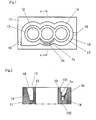
- FIG. 1 is a schematic plan view illustrating a state in which the cylinder bore wall insulating member is disposed in the cylinder block.
- FIG. 2 is a cross-sectional view taken along the line x-x in FIG. 1 .
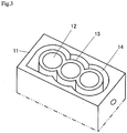
- FIG. 3 is a perspective view illustrating the cylinder block illustrated in FIG. 1 .
- FIG. 1 is a schematic plan view illustrating a state in which the cylinder bore wall insulating member is disposed in the cylinder block.
- FIG. 2 is a cross-sectional view taken along the line x-x in FIG. 1 .
- FIG. 3 is a perspective view illustrating the cylinder block illustrated in FIG. 1 .
- FIG. 1 is a schematic plan view illustrating a state in which the cylinder bore wall insulating member is disposed in the cylinder block.
- FIG. 2 is
- FIG. 4 is a schematic view illustrating the cylinder bore wall insulating member illustrated in FIG 1 (wherein (4-1) is a plan view, (4-2) is a cross-sectional view taken along the line x-x in FIG. 1 , and ( 4-3 ) is a side view)). Note that a plurality of insulating members may actually be disposed in the cylinder block illustrated in FIG. 1 , but only one insulating member is illustrated in FIG. 1 for convenience. In FIG. 2 , the area lower than the two-dot chain line is omitted.
- an open-deck cylinder block 11 for an automotive internal combustion engine (in which an insulating member 1a is disposed) includes bores 12 and a groove-like coolant passage 14, a piston moving upward and downward in each bore 12, and a coolant flowing through the groove-like coolant passage 14.
- the boundary between the bores 12 and the groove-like coolant passage 14 is defined by a cylinder bore wall 13.
- the cylinder block 11 also includes a coolant inlet 15 for supplying the coolant to the groove-like coolant passage 11, and a coolant outlet 16 for discharging the coolant from the groove-like coolant passage 11.
- the insulating member 1a has a contact surface 5a that comes in contact with the cylinder bore wall 13.
- the contact surface 5a has a shape that is curved along the wall surface of the cylinder bore wall 13 so that the contact surface 5a can come in contact with the wall surface of the cylinder bore wall 13.
- a securing member 2a that includes a coupling section 3a and a wall contact section 4a is attached to the insulating member 1a.
- the insulating member 1a and the securing member 2a are disposed in the groove-like coolant passage 14 so that the contact surface 5a comes in contact with a wall surface 17 of the cylinder bore wall 13 that defines the groove-like coolant passage 14.
- the internal combustion engine includes a piston, a cylinder head, a head gasket, and the like in addition to the cylinder block, the insulating member, and the securing member.
- the cylinder bore wall insulating member has the contact surface that comes in contact with the wall surface of the cylinder bore wall that forms the cylinder block of the internal combustion engine and defines the groove-like coolant passage.
- the cylinder bore wall insulating member covers the wall surface of the cylinder bore wall that defines the groove-like coolant passage with the contact surface that comes in contact with the wall surface of the cylinder bore wall that defines the groove-like coolant passage.
- the cylinder bore wall insulating member thus prevents a situation in which the coolant comes in direct contact with the wall surface of the cylinder bore wall that defines the groove-like coolant passage.
- the shape of the contact surface of the cylinder bore wall insulating member that comes in contact with the wall surface of the cylinder bore wall that defines the groove-like coolant passage is appropriately adjusted corresponding to each cylinder block so that the contact surface has a shape that coincides with the shape of the wall surface of the cylinder bore wall that defines the groove-like coolant passage.
- the cylinder bore wall insulating member may be formed of a nylon resin, an elastomer, a rubber material (e.g., ethylene-propylene-diene rubber (EPDM), or nitrile-butadiene rubber (NBR)), or the like taking account of long-life coolant resistance (LLC resistance) and heat resistance. It is preferable to use a rubber material such as EPDM or NBR as the material for forming the insulating member since such a rubber material exhibits excellent elasticity and adhesion as compared with a nylon resin, and exhibits excellent heat resistance as compared with an elastomer.
- a rubber material such as EPDM or NBR
- the thickness (indicated by t in FIG. 4 ) of the cylinder bore wall insulating member is appropriately selected taking account of the width of the groove-like coolant passage, the material that forms the insulating member, the estimated service period, the service conditions, and the like.
- the cylinder bore wall insulating member is disposed in the groove-like coolant passage so that the coolant does not come in contact with a lower area of the cylinder bore wall that defines the groove-like coolant passage.
- the shape, the arrangement, the arrangement position, the number, and the like of the cylinder bore wall insulating member(s) are appropriately selected so that the cylinder bore wall has the desired temperature distribution.
- the cylinder bore wall insulating member may be used within the temperature range of -40 to 200°C. It is preferable that the cylinder bore wall insulating member can endure a temperature of 120°C or more, and particularly preferably 150°C or more. The cylinder bore wall insulating member is also required to exhibit LLC resistance.
- the cylinder bore wall insulating member includes a reinforcing material that is provided inside the insulating member or on the back surface opposite to the contact surface so that the shape of the insulating member can be maintained.
- the cylinder bore wall insulating member is secured using the securing member so that the contact surface comes in contact with the cylinder bore wall.
- the insulating member 1a is secured using the securing member 2a.
- the securing member 2a includes the coupling section 3a and the wall contact section 4a.
- the wall contact section 4a comes in contact with a wall surface 18 of the groove-like coolant passage 14 opposite to the cylinder bore wall 13. Therefore, the contact surface of the wall contact section 4a is shaped to be fitted to the wall surface 18.
- the coupling section 3a couples the insulating member 1a and the wall contact section 4a.
- the coupling section 3a is tilted upward relative to a flow direction 21 of the coolant (see (4-3) in FIG. 4 ) so that a force that presses the insulating member 1a and the wall contact section 4a against the bottom of the groove-like coolant passage 14 is applied to the insulating member 1a and the wall contact section 4a due to the flow of the coolant, and the insulating member 1a is pressed against and secured on the cylinder bore wall 13.
- the coupling section 3a is outlined by the dotted line in (4-3) in FIG. 4 .
- a securing member not according to the invention may include a coupling section 3b, a wall contact section 4b, and an embedded section 22, for example.
- FIG. 5 is a schematic view illustrating another example of the cylinder bore wall insulating member and the securing member, wherein (5-1) is a plan view illustrating the securing member, and (5-2) is a cross-sectional view taken along the line y-y in (5-1).
- the embedded section 22 is embedded in an insulating member 1b.
- the insulating member 1b is pressed against and secured on the cylinder bore wall due to a spring biasing force caused by the coupling section 3b, the wall contact section 4b, and the embedded section 22.
- the securing member is not limited to the above examples as long as the insulating member can be secured on the cylinder bore wall so that the contact surface of the insulating member comes in contact with the wall surface of the cylinder bore wall.
- the insulating member may be bonded to the wall surface of the cylinder bore wall using an adhesive that exhibits heat resistance and LLC resistance (preferably an adhesive that exhibits low adhesion at room temperature (e.g., about 25°C) in the absence of moisture, but exhibits high adhesion at a high temperature (e.g., about 80 to 100°C) or in the presence of moisture).
- an adhesive that exhibits heat resistance and LLC resistance preferably an adhesive that exhibits low adhesion at room temperature (e.g., about 25°C) in the absence of moisture, but exhibits high adhesion at a high temperature (e.g., about 80 to 100°C) or in the presence of moisture).
- the overall shape of the cylinder bore wall insulating member and the shape of the securing member are not particularly limited as long as the flow of the coolant in the groove-like coolant passage is not hindered.
- the internal combustion engine according to one embodiment of the invention is characterized by including the cylinder bore wall insulating member (i.e., a cylinder bore wall insulating member as defined in claim 1 that has a contact surface that comes in contact with a wall surface of a cylinder bore wall that forms a cylinder block of the internal combustion engine and defines a groove-like coolant passage) that is disposed so that the contact surface comes in contact with the wall surface of the cylinder bore wall that defines the groove-like coolant passage.
- the cylinder bore wall insulating member i.e., a cylinder bore wall insulating member as defined in claim 1 that has a contact surface that comes in contact with a wall surface of a cylinder bore wall that forms a cylinder block of the internal combustion engine and defines a groove-like coolant passage
- the entire cylinder bore wall in the circumferential direction may be covered with the cylinder bore wall insulating member.
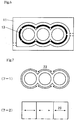
- the entire cylinder bore wall in the circumferential direction need not necessarily be covered with the cylinder bore wall insulating member (see FIG. 6 ) taking account of workability when disposing the cylinder bore wall insulating member, deformation determined by the coefficient of thermal expansion, cost-effectiveness, the heat insulation effect on the downstream side of the installation position of the insulating member due to stagnation of the flow of the coolant, and the like.
- the black-out area indicates the installation position of the insulating member.
- the term "circumferential direction" used herein in connection with the cylinder bore wall see 23 in FIG.
- FIG. 7 refers to a direction that extends along the cylinder bore wall 13 (i.e., a direction that corresponds to the transverse direction when the cylinder bore wall 13 is viewed from the side). Note that (7-1) in FIG. 7 is a plan view illustrating only the cylinder bore wall 13, and (7-2) in FIG. 7 is a front view illustrating only the cylinder bore wall 13.
- the cylinder bore wall insulating member is disposed in the internal combustion engine according to one embodiment of the invention so that the upper end of the cylinder bore wall insulating member in the vertical direction is positioned lower than the position that is lower than the upper end of the groove-like coolant passage by 1/3rd of the length from the upper end to the lower end of the groove-like coolant passage.
- the position that is lower than the upper end of the groove-like coolant passage by 1/3rd of the length from the upper end to the lower end of the groove-like coolant passage refers to the position that is lower than an upper end 131 of the groove-like coolant passage by 1/3rd of the length from the upper end 131 to a lower end 132 of the groove-like coolant passage.
- the position of the lower end of the cylinder bore wall insulating member in the vertical direction coincide with the position of the lower end 132 of the groove-like coolant passage.
- the lower end of the cylinder bore wall insulating member in the vertical direction may be positioned higher than the lower end 132 of the groove-like coolant passage taking account of the production of the cylinder bore wall insulating member, the shape of the groove-like coolant passage, and the like as long as the advantageous effects of the invention are not impaired.
- An internal combustion engine is normally configured so that a lower area of the cylinder bore wall has a low temperature, and is easily cooled with the coolant as compared with an upper area of the cylinder bore wall where the fuel explodes. Therefore, a large difference in temperature occurs between the upper area and the lower area of the cylinder bore wall.
- the internal combustion engine according to one embodiment of the invention in which the cylinder bore wall insulating member is disposed can prevent a situation in which the coolant comes in direct contact with the cylinder bore wall, it is possible to prevent a situation in which the temperature of the lower area of the cylinder bore wall becomes too low as compared with the temperature of the upper area of the cylinder bore wall.
- a cylinder bore wall insulating member having the shape illustrated in FIGS. 1, 2 , and 4 was produced. The specification of the insulating member is shown below.
- a cylinder block (provided with an observation window) having the shape illustrated in FIG. 3 and used for an experimental three-cylinder internal combustion engine was provided. The specification of the internal combustion engine is shown below.
- the insulating member was disposed in the groove-like coolant passage formed around the cylinder bore wall of the cylinder block.
- a coolant (temperature: 20 to 40°C) was passed through the groove-like coolant passage.
- the behavior of the insulating member was continuously observed through the observation window of the cylinder block to determine adhesion of the insulating member to the wall surface of the cylinder bore wall defining the groove-like coolant passage. It was confirmed that the insulating member adhered to (i.e., was not separated from) the wall surface of the cylinder bore wall defining the groove-like coolant passage.
- FIG. 8 After confirming adhesion to the wall surface and the like, a known computational fluid dynamics analysis was performed in a state in which the flow of the coolant was stable. The results are shown in FIG. 8 .
- the temperature distribution at the center indicates the temperature distribution of the cylinder bore wall of the center cylinder, and the temperature distribution on each side indicates the temperature distribution of the cylinder bore wall of each cylinder adjacent to the center cylinder.
- the sign A (Example 1) indicates the area in which the insulating member was provided.
- Example 2 Operations were performed in the same manner as in Example 1, except that the flexible lip member (spacer member) disclosed in JP-A-2008-31939 was used instead of the insulating member.
- the computational fluid dynamics analysis results are shown in FIG 8 .
- the amount of the coolant was limited in the area in which the insulating member was disposed in Example 1.
- Example 1 the temperature of the wall surface with which the insulating member came in contact was higher in Example 1 by 6 to 8°C as compared with Comparative Examples 1 and 2.
- Example 1 the wall surface of the cylinder bore wall defining the groove-like coolant passage showed a difference in temperature of 5°C in the vertical direction (i.e., an almost uniform temperature distribution was obtained).
- a fuel-efficient internal combustion engine can be provided.
Landscapes
- Engineering & Computer Science (AREA)
- Chemical & Material Sciences (AREA)
- Combustion & Propulsion (AREA)
- Mechanical Engineering (AREA)
- General Engineering & Computer Science (AREA)
- Cylinder Crankcases Of Internal Combustion Engines (AREA)
Applications Claiming Priority (2)
| Application Number | Priority Date | Filing Date | Title |
|---|---|---|---|
| JP2010141285A JP2012007479A (ja) | 2010-06-22 | 2010-06-22 | シリンダボア壁の保温部材、内燃機関及び自動車 |
| PCT/JP2011/063049 WO2011162096A1 (ja) | 2010-06-22 | 2011-06-07 | シリンダボア壁の保温部材、内燃機関及び自動車 |
Publications (3)
| Publication Number | Publication Date |
|---|---|
| EP2587035A1 EP2587035A1 (en) | 2013-05-01 |
| EP2587035A4 EP2587035A4 (en) | 2015-05-20 |
| EP2587035B1 true EP2587035B1 (en) | 2018-06-06 |
Family
ID=45371292
Family Applications (1)
| Application Number | Title | Priority Date | Filing Date |
|---|---|---|---|
| EP11797982.3A Active EP2587035B1 (en) | 2010-06-22 | 2011-06-07 | Heat retention member for cylinder bore wall, internal combustion engine, and automobile |
Country Status (5)
| Country | Link |
|---|---|
| US (2) | US9032916B2 (enExample) |
| EP (1) | EP2587035B1 (enExample) |
| JP (1) | JP2012007479A (enExample) |
| CN (1) | CN102906406B (enExample) |
| WO (1) | WO2011162096A1 (enExample) |
Families Citing this family (19)
| Publication number | Priority date | Publication date | Assignee | Title |
|---|---|---|---|---|
| DE102012204805A1 (de) * | 2012-03-26 | 2013-09-26 | Bayerische Motoren Werke Aktiengesellschaft | Kurbelgehäuse für eine Brennkraftmaschine |
| JP5880471B2 (ja) * | 2013-02-21 | 2016-03-09 | マツダ株式会社 | 多気筒エンジンの冷却装置 |
| JP5830049B2 (ja) * | 2013-03-15 | 2015-12-09 | ニチアス株式会社 | シリンダボア壁の保温部材の組み付け方法 |
| JP6249751B2 (ja) * | 2013-12-11 | 2017-12-20 | ダイハツ工業株式会社 | ウォータジャケットスペーサ |
| JP6199911B2 (ja) * | 2014-03-31 | 2017-09-20 | トヨタ自動車株式会社 | ウォータージャケットスペーサ |
| JP6297393B2 (ja) * | 2014-04-11 | 2018-03-20 | ニチアス株式会社 | シリンダボア壁の保温具、内燃機関及び自動車 |
| JP6340234B2 (ja) * | 2014-04-11 | 2018-06-06 | ニチアス株式会社 | シリンダボア壁の保温具、内燃機関及び自動車 |
| JP6346497B2 (ja) * | 2014-06-06 | 2018-06-20 | Nok株式会社 | ウォータージャケットスペーサ |
| DE112015005710T5 (de) * | 2014-12-22 | 2017-09-14 | Uchiyama Manufacturing Corp. | Regelungsbauglied |
| WO2016104444A1 (ja) * | 2014-12-22 | 2016-06-30 | ニチアス株式会社 | ウォータージャケットの冷却水流路の区画部品、内燃機関及び自動車 |
| JP6454566B2 (ja) * | 2015-02-23 | 2019-01-16 | 内山工業株式会社 | 規制部材 |
| JP6297531B2 (ja) * | 2015-11-05 | 2018-03-20 | ニチアス株式会社 | シリンダボア壁の保温具、内燃機関及び自動車 |
| JP6283011B2 (ja) | 2015-11-12 | 2018-02-21 | ニチアス株式会社 | シリンダボア壁の保温具、内燃機関及び自動車 |
| KR101846630B1 (ko) * | 2015-12-07 | 2018-04-06 | 현대자동차주식회사 | 블록인서트 및 이를 포함하는 차량 엔진의 실린더 구조 |
| KR101795279B1 (ko) * | 2016-06-22 | 2017-11-08 | 현대자동차주식회사 | 내연기관의 분리냉각 시스템 |
| JP6486304B2 (ja) * | 2016-09-21 | 2019-03-20 | ニチアス株式会社 | シリンダボア壁の保温具、内燃機関及び自動車 |
| JP6710169B2 (ja) * | 2017-02-17 | 2020-06-17 | ニチアス株式会社 | 内燃機関 |
| CN110966111B (zh) * | 2018-09-30 | 2021-11-23 | 上海汽车集团股份有限公司 | 辅助冷却装置和发动机 |
| KR20200067531A (ko) * | 2018-12-04 | 2020-06-12 | 현대자동차주식회사 | 실린더블록용 워터재킷의 내장 구조물 |
Citations (1)
| Publication number | Priority date | Publication date | Assignee | Title |
|---|---|---|---|---|
| WO2008016127A1 (en) * | 2006-07-31 | 2008-02-07 | Toyota Jidosha Kabushiki Kaisha | Partition member for cooling passage of internal combustion engine, cooling mechanism of internal combustion engine, and method for forming the cooling mechanism |
Family Cites Families (20)
| Publication number | Priority date | Publication date | Assignee | Title |
|---|---|---|---|---|
| US2127825A (en) * | 1934-04-23 | 1938-08-23 | Messerschmitt Boelkow Blohm | Engine cylinder |
| FR2184240A5 (en) * | 1972-05-10 | 1973-12-21 | Barthod Malat Jean | Rotating jet tank scouring appts - with independent mechanical drive ensuring-ring different jet orientation after each rotation |
| US5542381A (en) * | 1994-02-07 | 1996-08-06 | Nissan Motor Co., Ltd. | Cylinder block for liquid-cooled engine |
| US5890719A (en) * | 1996-08-27 | 1999-04-06 | Parker-Hannifin Corporation | Combination metal and elastomer cylinder head gasket |
| JP3753413B2 (ja) * | 2000-08-07 | 2006-03-08 | 石川ガスケット株式会社 | 多気筒用のヘッドガスケット |
| JP3936247B2 (ja) * | 2002-06-12 | 2007-06-27 | トヨタ自動車株式会社 | エンジンの冷却装置 |
| JP3967636B2 (ja) * | 2002-06-12 | 2007-08-29 | トヨタ自動車株式会社 | エンジンの冷却装置 |
| JP4017584B2 (ja) * | 2003-10-17 | 2007-12-05 | トヨタ自動車株式会社 | シリンダブロックの冷却構造 |
| US7032547B2 (en) * | 2004-04-22 | 2006-04-25 | Honda Motor Co., Ltd. | Cylinder block cooling arrangement for multi-cylinder internal combustion engine |
| US7287757B2 (en) * | 2005-06-28 | 2007-10-30 | Dana Corporation | Optimized wave bead with full bead design |
| JP4240020B2 (ja) * | 2005-08-22 | 2009-03-18 | トヨタ自動車株式会社 | 内燃機関の暖機装置 |
| JP2007085329A (ja) * | 2005-08-22 | 2007-04-05 | Toyota Motor Corp | 内燃機関の暖機装置 |
| JP4465313B2 (ja) * | 2005-09-05 | 2010-05-19 | 内山工業株式会社 | ウォータジャケットスペーサ |
| JP4356690B2 (ja) * | 2005-12-09 | 2009-11-04 | 三菱自動車工業株式会社 | ウォータージャケットスペーサ |
| JP4345754B2 (ja) * | 2006-02-09 | 2009-10-14 | トヨタ自動車株式会社 | 蓄熱装置及びエンジン |
| JP2007309221A (ja) * | 2006-05-18 | 2007-11-29 | Toyota Motor Corp | 内燃機関冷却機構、予備昇温用流路形成方法及び区画部材 |
| US20100031902A1 (en) * | 2007-10-10 | 2010-02-11 | Brunswick Corporation | Outboard motor cooling system with inserts to affect operating temperatures |
| JP5064471B2 (ja) * | 2009-11-19 | 2012-10-31 | 本田技研工業株式会社 | 内燃機関の冷却構造 |
| CN102072001B (zh) * | 2009-11-19 | 2013-06-19 | 本田技研工业株式会社 | 内燃机的冷却结构 |
| JP5610290B2 (ja) * | 2010-11-29 | 2014-10-22 | 内山工業株式会社 | ウォータジャケットスペーサ |
-
2010
- 2010-06-22 JP JP2010141285A patent/JP2012007479A/ja active Pending
-
2011
- 2011-06-07 WO PCT/JP2011/063049 patent/WO2011162096A1/ja not_active Ceased
- 2011-06-07 EP EP11797982.3A patent/EP2587035B1/en active Active
- 2011-06-07 CN CN201180025389.XA patent/CN102906406B/zh active Active
- 2011-06-07 US US13/806,417 patent/US9032916B2/en active Active
-
2015
- 2015-05-12 US US14/710,246 patent/US10077736B2/en active Active
Patent Citations (1)
| Publication number | Priority date | Publication date | Assignee | Title |
|---|---|---|---|---|
| WO2008016127A1 (en) * | 2006-07-31 | 2008-02-07 | Toyota Jidosha Kabushiki Kaisha | Partition member for cooling passage of internal combustion engine, cooling mechanism of internal combustion engine, and method for forming the cooling mechanism |
Also Published As
| Publication number | Publication date |
|---|---|
| US10077736B2 (en) | 2018-09-18 |
| US20150240743A1 (en) | 2015-08-27 |
| EP2587035A4 (en) | 2015-05-20 |
| JP2012007479A (ja) | 2012-01-12 |
| US9032916B2 (en) | 2015-05-19 |
| CN102906406A (zh) | 2013-01-30 |
| WO2011162096A1 (ja) | 2011-12-29 |
| CN102906406B (zh) | 2016-03-16 |
| US20130160725A1 (en) | 2013-06-27 |
| EP2587035A1 (en) | 2013-05-01 |
Similar Documents
| Publication | Publication Date | Title |
|---|---|---|
| EP2587035B1 (en) | Heat retention member for cylinder bore wall, internal combustion engine, and automobile | |
| CN101490379B (zh) | 用于内燃机的冷却通道的分割部件、内燃机的冷却结构及用于形成冷却结构的方法 | |
| EP2495412B1 (en) | Internal combustion engine | |
| US10221752B2 (en) | Split cooling apparatus for internal combustion engine | |
| CN203847263U (zh) | 发动机、气缸体及气缸盖垫片 | |
| US9790838B2 (en) | Engine cooling system | |
| US8256389B2 (en) | Cylinder block | |
| CN102072002A (zh) | 内燃机的冷却结构 | |
| US20160017838A1 (en) | Temperature maintaining member for cylinder-bore wall | |
| US20170342939A1 (en) | Dividing component of cooling water channel of water jacket, internal combustion engine, and automobile | |
| KR101144517B1 (ko) | 내연기관의 냉각장치 및 워터재킷용 인서트 | |
| JP5468476B2 (ja) | シリンダボア壁の保温構造体及び内燃機関 | |
| US5873578A (en) | Gasket for internal combustion engine and method for forming same | |
| US10161352B2 (en) | Engine block assembly | |
| EP3379114A1 (en) | Cylinder head gasket | |
| EP1728014B1 (en) | Gasket | |
| US7370639B2 (en) | Supercharged diesel engine with a common-rail injection system | |
| JP6216731B2 (ja) | シリンダボア壁の保温部材、内燃機関及び自動車 | |
| JP6243068B2 (ja) | シリンダボア壁の保温部材、内燃機関及び自動車 | |
| US6152090A (en) | Engine cylinder block | |
| US20190383229A1 (en) | Cylinder bore wall thermal insulator, internal combustion engine, and automobile | |
| KR200416238Y1 (ko) | 실린더 헤드 개스킷용 스토퍼 | |
| JP2005273469A (ja) | シリンダブロックの冷却構造 | |
| WO2015009703A2 (en) | Cylinder head gaskets with push-rod eyelets | |
| JP2013108563A (ja) | 可変圧縮比エンジンのブーツシール構造 |
Legal Events
| Date | Code | Title | Description |
|---|---|---|---|
| PUAI | Public reference made under article 153(3) epc to a published international application that has entered the european phase |
Free format text: ORIGINAL CODE: 0009012 |
|
| 17P | Request for examination filed |
Effective date: 20121213 |
|
| AK | Designated contracting states |
Kind code of ref document: A1 Designated state(s): AL AT BE BG CH CY CZ DE DK EE ES FI FR GB GR HR HU IE IS IT LI LT LU LV MC MK MT NL NO PL PT RO RS SE SI SK SM TR |
|
| DAX | Request for extension of the european patent (deleted) | ||
| RA4 | Supplementary search report drawn up and despatched (corrected) |
Effective date: 20150422 |
|
| RIC1 | Information provided on ipc code assigned before grant |
Ipc: F02F 1/14 20060101AFI20150416BHEP Ipc: F02F 1/10 20060101ALI20150416BHEP Ipc: F01P 3/02 20060101ALI20150416BHEP |
|
| 17Q | First examination report despatched |
Effective date: 20161221 |
|
| GRAP | Despatch of communication of intention to grant a patent |
Free format text: ORIGINAL CODE: EPIDOSNIGR1 |
|
| INTG | Intention to grant announced |
Effective date: 20171219 |
|
| GRAS | Grant fee paid |
Free format text: ORIGINAL CODE: EPIDOSNIGR3 |
|
| GRAJ | Information related to disapproval of communication of intention to grant by the applicant or resumption of examination proceedings by the epo deleted |
Free format text: ORIGINAL CODE: EPIDOSDIGR1 |
|
| GRAL | Information related to payment of fee for publishing/printing deleted |
Free format text: ORIGINAL CODE: EPIDOSDIGR3 |
|
| GRAR | Information related to intention to grant a patent recorded |
Free format text: ORIGINAL CODE: EPIDOSNIGR71 |
|
| GRAA | (expected) grant |
Free format text: ORIGINAL CODE: 0009210 |
|
| INTC | Intention to grant announced (deleted) | ||
| AK | Designated contracting states |
Kind code of ref document: B1 Designated state(s): AL AT BE BG CH CY CZ DE DK EE ES FI FR GB GR HR HU IE IS IT LI LT LU LV MC MK MT NL NO PL PT RO RS SE SI SK SM TR |
|
| INTG | Intention to grant announced |
Effective date: 20180427 |
|
| REG | Reference to a national code |
Ref country code: GB Ref legal event code: FG4D |
|
| REG | Reference to a national code |
Ref country code: CH Ref legal event code: EP Ref country code: AT Ref legal event code: REF Ref document number: 1006362 Country of ref document: AT Kind code of ref document: T Effective date: 20180615 |
|
| RAP2 | Party data changed (patent owner data changed or rights of a patent transferred) |
Owner name: NICHIAS CORPORATION |
|
| REG | Reference to a national code |
Ref country code: IE Ref legal event code: FG4D |
|
| REG | Reference to a national code |
Ref country code: DE Ref legal event code: R096 Ref document number: 602011049087 Country of ref document: DE |
|
| REG | Reference to a national code |
Ref country code: NL Ref legal event code: MP Effective date: 20180606 |
|
| REG | Reference to a national code |
Ref country code: LT Ref legal event code: MG4D |
|
| PG25 | Lapsed in a contracting state [announced via postgrant information from national office to epo] |
Ref country code: NO Free format text: LAPSE BECAUSE OF FAILURE TO SUBMIT A TRANSLATION OF THE DESCRIPTION OR TO PAY THE FEE WITHIN THE PRESCRIBED TIME-LIMIT Effective date: 20180906 Ref country code: FI Free format text: LAPSE BECAUSE OF FAILURE TO SUBMIT A TRANSLATION OF THE DESCRIPTION OR TO PAY THE FEE WITHIN THE PRESCRIBED TIME-LIMIT Effective date: 20180606 Ref country code: BG Free format text: LAPSE BECAUSE OF FAILURE TO SUBMIT A TRANSLATION OF THE DESCRIPTION OR TO PAY THE FEE WITHIN THE PRESCRIBED TIME-LIMIT Effective date: 20180906 Ref country code: SE Free format text: LAPSE BECAUSE OF FAILURE TO SUBMIT A TRANSLATION OF THE DESCRIPTION OR TO PAY THE FEE WITHIN THE PRESCRIBED TIME-LIMIT Effective date: 20180606 Ref country code: CY Free format text: LAPSE BECAUSE OF FAILURE TO SUBMIT A TRANSLATION OF THE DESCRIPTION OR TO PAY THE FEE WITHIN THE PRESCRIBED TIME-LIMIT Effective date: 20180606 Ref country code: ES Free format text: LAPSE BECAUSE OF FAILURE TO SUBMIT A TRANSLATION OF THE DESCRIPTION OR TO PAY THE FEE WITHIN THE PRESCRIBED TIME-LIMIT Effective date: 20180606 Ref country code: LT Free format text: LAPSE BECAUSE OF FAILURE TO SUBMIT A TRANSLATION OF THE DESCRIPTION OR TO PAY THE FEE WITHIN THE PRESCRIBED TIME-LIMIT Effective date: 20180606 |
|
| PG25 | Lapsed in a contracting state [announced via postgrant information from national office to epo] |
Ref country code: RS Free format text: LAPSE BECAUSE OF FAILURE TO SUBMIT A TRANSLATION OF THE DESCRIPTION OR TO PAY THE FEE WITHIN THE PRESCRIBED TIME-LIMIT Effective date: 20180606 Ref country code: GR Free format text: LAPSE BECAUSE OF FAILURE TO SUBMIT A TRANSLATION OF THE DESCRIPTION OR TO PAY THE FEE WITHIN THE PRESCRIBED TIME-LIMIT Effective date: 20180907 Ref country code: HR Free format text: LAPSE BECAUSE OF FAILURE TO SUBMIT A TRANSLATION OF THE DESCRIPTION OR TO PAY THE FEE WITHIN THE PRESCRIBED TIME-LIMIT Effective date: 20180606 Ref country code: LV Free format text: LAPSE BECAUSE OF FAILURE TO SUBMIT A TRANSLATION OF THE DESCRIPTION OR TO PAY THE FEE WITHIN THE PRESCRIBED TIME-LIMIT Effective date: 20180606 |
|
| REG | Reference to a national code |
Ref country code: AT Ref legal event code: MK05 Ref document number: 1006362 Country of ref document: AT Kind code of ref document: T Effective date: 20180606 |
|
| PG25 | Lapsed in a contracting state [announced via postgrant information from national office to epo] |
Ref country code: NL Free format text: LAPSE BECAUSE OF FAILURE TO SUBMIT A TRANSLATION OF THE DESCRIPTION OR TO PAY THE FEE WITHIN THE PRESCRIBED TIME-LIMIT Effective date: 20180606 |
|
| PG25 | Lapsed in a contracting state [announced via postgrant information from national office to epo] |
Ref country code: SK Free format text: LAPSE BECAUSE OF FAILURE TO SUBMIT A TRANSLATION OF THE DESCRIPTION OR TO PAY THE FEE WITHIN THE PRESCRIBED TIME-LIMIT Effective date: 20180606 Ref country code: RO Free format text: LAPSE BECAUSE OF FAILURE TO SUBMIT A TRANSLATION OF THE DESCRIPTION OR TO PAY THE FEE WITHIN THE PRESCRIBED TIME-LIMIT Effective date: 20180606 Ref country code: IS Free format text: LAPSE BECAUSE OF FAILURE TO SUBMIT A TRANSLATION OF THE DESCRIPTION OR TO PAY THE FEE WITHIN THE PRESCRIBED TIME-LIMIT Effective date: 20181006 Ref country code: CZ Free format text: LAPSE BECAUSE OF FAILURE TO SUBMIT A TRANSLATION OF THE DESCRIPTION OR TO PAY THE FEE WITHIN THE PRESCRIBED TIME-LIMIT Effective date: 20180606 Ref country code: EE Free format text: LAPSE BECAUSE OF FAILURE TO SUBMIT A TRANSLATION OF THE DESCRIPTION OR TO PAY THE FEE WITHIN THE PRESCRIBED TIME-LIMIT Effective date: 20180606 Ref country code: AT Free format text: LAPSE BECAUSE OF FAILURE TO SUBMIT A TRANSLATION OF THE DESCRIPTION OR TO PAY THE FEE WITHIN THE PRESCRIBED TIME-LIMIT Effective date: 20180606 Ref country code: PL Free format text: LAPSE BECAUSE OF FAILURE TO SUBMIT A TRANSLATION OF THE DESCRIPTION OR TO PAY THE FEE WITHIN THE PRESCRIBED TIME-LIMIT Effective date: 20180606 |
|
| REG | Reference to a national code |
Ref country code: CH Ref legal event code: PL |
|
| PG25 | Lapsed in a contracting state [announced via postgrant information from national office to epo] |
Ref country code: SM Free format text: LAPSE BECAUSE OF FAILURE TO SUBMIT A TRANSLATION OF THE DESCRIPTION OR TO PAY THE FEE WITHIN THE PRESCRIBED TIME-LIMIT Effective date: 20180606 Ref country code: IT Free format text: LAPSE BECAUSE OF FAILURE TO SUBMIT A TRANSLATION OF THE DESCRIPTION OR TO PAY THE FEE WITHIN THE PRESCRIBED TIME-LIMIT Effective date: 20180606 |
|
| REG | Reference to a national code |
Ref country code: BE Ref legal event code: MM Effective date: 20180630 |
|
| REG | Reference to a national code |
Ref country code: DE Ref legal event code: R097 Ref document number: 602011049087 Country of ref document: DE |
|
| REG | Reference to a national code |
Ref country code: IE Ref legal event code: MM4A |
|
| PG25 | Lapsed in a contracting state [announced via postgrant information from national office to epo] |
Ref country code: LU Free format text: LAPSE BECAUSE OF NON-PAYMENT OF DUE FEES Effective date: 20180607 Ref country code: MC Free format text: LAPSE BECAUSE OF FAILURE TO SUBMIT A TRANSLATION OF THE DESCRIPTION OR TO PAY THE FEE WITHIN THE PRESCRIBED TIME-LIMIT Effective date: 20180606 |
|
| PLBE | No opposition filed within time limit |
Free format text: ORIGINAL CODE: 0009261 |
|
| STAA | Information on the status of an ep patent application or granted ep patent |
Free format text: STATUS: NO OPPOSITION FILED WITHIN TIME LIMIT |
|
| PG25 | Lapsed in a contracting state [announced via postgrant information from national office to epo] |
Ref country code: CH Free format text: LAPSE BECAUSE OF NON-PAYMENT OF DUE FEES Effective date: 20180630 Ref country code: IE Free format text: LAPSE BECAUSE OF NON-PAYMENT OF DUE FEES Effective date: 20180607 Ref country code: LI Free format text: LAPSE BECAUSE OF NON-PAYMENT OF DUE FEES Effective date: 20180630 |
|
| 26N | No opposition filed |
Effective date: 20190307 |
|
| PG25 | Lapsed in a contracting state [announced via postgrant information from national office to epo] |
Ref country code: DK Free format text: LAPSE BECAUSE OF FAILURE TO SUBMIT A TRANSLATION OF THE DESCRIPTION OR TO PAY THE FEE WITHIN THE PRESCRIBED TIME-LIMIT Effective date: 20180606 Ref country code: SI Free format text: LAPSE BECAUSE OF FAILURE TO SUBMIT A TRANSLATION OF THE DESCRIPTION OR TO PAY THE FEE WITHIN THE PRESCRIBED TIME-LIMIT Effective date: 20180606 Ref country code: BE Free format text: LAPSE BECAUSE OF NON-PAYMENT OF DUE FEES Effective date: 20180630 |
|
| PG25 | Lapsed in a contracting state [announced via postgrant information from national office to epo] |
Ref country code: FR Free format text: LAPSE BECAUSE OF NON-PAYMENT OF DUE FEES Effective date: 20180806 |
|
| PG25 | Lapsed in a contracting state [announced via postgrant information from national office to epo] |
Ref country code: AL Free format text: LAPSE BECAUSE OF FAILURE TO SUBMIT A TRANSLATION OF THE DESCRIPTION OR TO PAY THE FEE WITHIN THE PRESCRIBED TIME-LIMIT Effective date: 20180606 |
|
| PG25 | Lapsed in a contracting state [announced via postgrant information from national office to epo] |
Ref country code: MT Free format text: LAPSE BECAUSE OF NON-PAYMENT OF DUE FEES Effective date: 20180607 |
|
| PG25 | Lapsed in a contracting state [announced via postgrant information from national office to epo] |
Ref country code: TR Free format text: LAPSE BECAUSE OF FAILURE TO SUBMIT A TRANSLATION OF THE DESCRIPTION OR TO PAY THE FEE WITHIN THE PRESCRIBED TIME-LIMIT Effective date: 20180606 |
|
| PG25 | Lapsed in a contracting state [announced via postgrant information from national office to epo] |
Ref country code: PT Free format text: LAPSE BECAUSE OF FAILURE TO SUBMIT A TRANSLATION OF THE DESCRIPTION OR TO PAY THE FEE WITHIN THE PRESCRIBED TIME-LIMIT Effective date: 20180606 Ref country code: HU Free format text: LAPSE BECAUSE OF FAILURE TO SUBMIT A TRANSLATION OF THE DESCRIPTION OR TO PAY THE FEE WITHIN THE PRESCRIBED TIME-LIMIT; INVALID AB INITIO Effective date: 20110607 |
|
| PG25 | Lapsed in a contracting state [announced via postgrant information from national office to epo] |
Ref country code: MK Free format text: LAPSE BECAUSE OF NON-PAYMENT OF DUE FEES Effective date: 20180606 |
|
| P01 | Opt-out of the competence of the unified patent court (upc) registered |
Effective date: 20230512 |
|
| PGFP | Annual fee paid to national office [announced via postgrant information from national office to epo] |
Ref country code: DE Payment date: 20250429 Year of fee payment: 15 |
|
| PGFP | Annual fee paid to national office [announced via postgrant information from national office to epo] |
Ref country code: GB Payment date: 20250501 Year of fee payment: 15 |