EP2583879B1 - Dispositif de commande électronique - Google Patents
Dispositif de commande électronique Download PDFInfo
- Publication number
- EP2583879B1 EP2583879B1 EP11795780.3A EP11795780A EP2583879B1 EP 2583879 B1 EP2583879 B1 EP 2583879B1 EP 11795780 A EP11795780 A EP 11795780A EP 2583879 B1 EP2583879 B1 EP 2583879B1
- Authority
- EP
- European Patent Office
- Prior art keywords
- control unit
- power supply
- unit
- control
- supply units
- Prior art date
- Legal status (The legal status is an assumption and is not a legal conclusion. Google has not performed a legal analysis and makes no representation as to the accuracy of the status listed.)
- Active
Links
- 238000010586 diagram Methods 0.000 description 43
- 239000004065 semiconductor Substances 0.000 description 38
- 238000000034 method Methods 0.000 description 21
- 238000012545 processing Methods 0.000 description 8
- 238000004364 calculation method Methods 0.000 description 4
- 238000012544 monitoring process Methods 0.000 description 3
- 238000006243 chemical reaction Methods 0.000 description 2
- 231100001261 hazardous Toxicity 0.000 description 2
- 238000013459 approach Methods 0.000 description 1
- 239000003990 capacitor Substances 0.000 description 1
- 230000015556 catabolic process Effects 0.000 description 1
- 230000000052 comparative effect Effects 0.000 description 1
- 238000012937 correction Methods 0.000 description 1
- 230000001419 dependent effect Effects 0.000 description 1
- 238000001514 detection method Methods 0.000 description 1
- 238000011161 development Methods 0.000 description 1
- 230000018109 developmental process Effects 0.000 description 1
- 230000000694 effects Effects 0.000 description 1
- 238000005516 engineering process Methods 0.000 description 1
- 238000007689 inspection Methods 0.000 description 1
- 230000010354 integration Effects 0.000 description 1
Images


Classifications
-
- B—PERFORMING OPERATIONS; TRANSPORTING
- B60—VEHICLES IN GENERAL
- B60R—VEHICLES, VEHICLE FITTINGS, OR VEHICLE PARTS, NOT OTHERWISE PROVIDED FOR
- B60R16/00—Electric or fluid circuits specially adapted for vehicles and not otherwise provided for; Arrangement of elements of electric or fluid circuits specially adapted for vehicles and not otherwise provided for
- B60R16/02—Electric or fluid circuits specially adapted for vehicles and not otherwise provided for; Arrangement of elements of electric or fluid circuits specially adapted for vehicles and not otherwise provided for electric constitutive elements
- B60R16/03—Electric or fluid circuits specially adapted for vehicles and not otherwise provided for; Arrangement of elements of electric or fluid circuits specially adapted for vehicles and not otherwise provided for electric constitutive elements for supply of electrical power to vehicle subsystems or for
- B60R16/033—Electric or fluid circuits specially adapted for vehicles and not otherwise provided for; Arrangement of elements of electric or fluid circuits specially adapted for vehicles and not otherwise provided for electric constitutive elements for supply of electrical power to vehicle subsystems or for characterised by the use of electrical cells or batteries
-
- B—PERFORMING OPERATIONS; TRANSPORTING
- B62—LAND VEHICLES FOR TRAVELLING OTHERWISE THAN ON RAILS
- B62D—MOTOR VEHICLES; TRAILERS
- B62D5/00—Power-assisted or power-driven steering
- B62D5/04—Power-assisted or power-driven steering electrical, e.g. using an electric servo-motor connected to, or forming part of, the steering gear
- B62D5/0457—Power-assisted or power-driven steering electrical, e.g. using an electric servo-motor connected to, or forming part of, the steering gear characterised by control features of the drive means as such
- B62D5/0481—Power-assisted or power-driven steering electrical, e.g. using an electric servo-motor connected to, or forming part of, the steering gear characterised by control features of the drive means as such monitoring the steering system, e.g. failures
- B62D5/0484—Power-assisted or power-driven steering electrical, e.g. using an electric servo-motor connected to, or forming part of, the steering gear characterised by control features of the drive means as such monitoring the steering system, e.g. failures for reaction to failures, e.g. limp home
-
- B—PERFORMING OPERATIONS; TRANSPORTING
- B62—LAND VEHICLES FOR TRAVELLING OTHERWISE THAN ON RAILS
- B62D—MOTOR VEHICLES; TRAILERS
- B62D6/00—Arrangements for automatically controlling steering depending on driving conditions sensed and responded to, e.g. control circuits
- B62D6/08—Arrangements for automatically controlling steering depending on driving conditions sensed and responded to, e.g. control circuits responsive only to driver input torque
-
- Y—GENERAL TAGGING OF NEW TECHNOLOGICAL DEVELOPMENTS; GENERAL TAGGING OF CROSS-SECTIONAL TECHNOLOGIES SPANNING OVER SEVERAL SECTIONS OF THE IPC; TECHNICAL SUBJECTS COVERED BY FORMER USPC CROSS-REFERENCE ART COLLECTIONS [XRACs] AND DIGESTS
- Y02—TECHNOLOGIES OR APPLICATIONS FOR MITIGATION OR ADAPTATION AGAINST CLIMATE CHANGE
- Y02T—CLIMATE CHANGE MITIGATION TECHNOLOGIES RELATED TO TRANSPORTATION
- Y02T10/00—Road transport of goods or passengers
- Y02T10/80—Technologies aiming to reduce greenhouse gasses emissions common to all road transportation technologies
- Y02T10/92—Energy efficient charging or discharging systems for batteries, ultracapacitors, supercapacitors or double-layer capacitors specially adapted for vehicles
Definitions
- the present invention relates, in general, to electronic control apparatuses and, in particular, to an electronic control apparatus for automobiles that enables continued operation, for example, even in faulty conditions.
- a method is widely known in which a monitoring microprocessor is incorporated, and the monitoring microprocessor and the first microprocessor cross-check each other. Another known method makes the first microprocessor redundant (doubling), thereby making a comparative check of outputs from the two first microprocessors.
- a control logic circuit or a data path may be formed of redundancy code logic, such as a parity or an error detection and correction code, or an inspection circuit may be incorporated to perform a self-check.
- redundancy code logic such as a parity or an error detection and correction code
- an inspection circuit may be incorporated to perform a self-check.
- a torque monitoring function is incorporated in addition to a first microprocessor and the first microprocessor is determined to be faulty when excessive steering torque is input from a torque sensor.
- a method is widely used in which each of subsystems constituting the control apparatus is made redundant.
- Patent Document 1 JP-2005-315840-A In WO 2009 154119 A1 an electric power steering apparatus is described.
- the apparatus drives a motor to generate a steering assist force according to a steering torque and includes an output circuit for supplying the motor with electric power from at least one of the battery and auxiliary power supplies. Despite of a breakdown of the battery the output circuit can supply to the motor the electric path from the auxiliary power supplies.
- the one for making the subsystems redundant to enable continued operation requires further consideration of circuit scale, dimensions, weight, and cost reduction.
- the method for making the subsystems redundant entails concern over an increase in circuit scale, dimensions, weight, and cost.
- the present invention has been made in view of the foregoing and it is an object of the present invention to provide an electronic control apparatus that enables continued operation during a faulty condition, while preventing circuit scale, dimensions, weight, and cost from increasing.
- the power supply unit is made redundant and its capacity is divided through measure (1) above out of the measures described above. Each of power supply units can then have a smaller capacity and redundancy prevents the circuit scale from being enlarged.
- measure (3) allows the slave control unit provided for a case in which the master control unit fails to be utilized as means for reduction in power consumption of processing functions when the power supply unit is faulty.
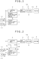
- Fig. 1 is a block diagram illustrating a first embodiment.
- the first embodiment represents a basic exemplary arrangement of an electronic control apparatus for automobiles according to an aspect of the present invention.
- the electronic control apparatus includes a control unit 2, two power supply units 1-1, 1-2, a pre-driver 5, a driver 6, a motor 8, and a power supply fault detector unit 3.
- Each of the power supply units 1-1, 1-2 includes, for example, a voltage regulator, connected to a battery or a generator, for supplying a predetermined voltage.
- the power supply units 1-1, 1-2 are connected to the control unit 2 via diodes D1, D2, respectively, thereby supplying the control unit 2 with electric power.
- the control unit 2 receives the electric power from the two power supply units 1-1, 1-2, the control unit 2 outputs a control signal (three-phase, six lines each for upper and lower arms) to the pre-driver 5.
- the pre-driver 5 drives the driver 6 according to the control signal input thereto from the control unit 2.
- the driver 6 is connected to the battery or the generator not shown via a main relay 7-0. Through switching of the electric power supplied from the battery or the generator, the driver 6 outputs current to the motor 8 via a phase output relay 7-1, thereby driving the motor 8.
- the main relay 7-0 and the phase output relay 7-1 function to stop operation of the driver 6 and the motor 8 thereby ensuring safety, when a fault occurs in the control unit 2, the pre-driver 5, the driver 6, or the motor 8.
- the power supply fault detector unit 3 monitors output voltages of the power supply units 1-1, 1-2. Determining that either one of the power supply units 1-1, 1-2 is faulty based on the output voltage falling outside a predetermined range, the power supply fault detector unit 3 outputs an electric power reduction signal 30 to the control unit 2.
- the control unit 2 operates in a normal mode on the electric power supplied from the power supply units 1-1, 1-2, when none of the power supply units 1-1, 1-2 is faulty. If any of the power supply units 1-1, 1-2 is faulty, the control unit 2 operates in an energy saving mode on the electric power supplied from the power supply unit that remains fully operational, consuming less power.
- the control unit 2 includes power consumption reduction means 2' as an internal function. Receiving an input of the electric power reduction signal 30 from the power supply fault detector unit 3, the power consumption reduction means 2' reduces power consumption of the control unit 2.
- Fig. 2 is a block diagram illustrating a second embodiment that demonstrates a method for reducing power consumption of the control unit.
- a power supply fault detector unit 3 When either one of power supply units 1-1, 1-2 is faulty, a power supply fault detector unit 3 outputs a clock reduction signal 30a and a parameter change signal 30b as an electric power reduction signal 30.
- Power consumption reduction means 2' of a control unit 2 includes clock reduction means 2a and parameter change means 2b. Based on the clock reduction signal 30a input from the power supply fault detector unit 3, the clock reduction means 2a reduces an operating clock frequency of the control unit 2 to thereby reduce power consumption. It should be noted that, when the operating clock frequency is reduced, a time scale in operation of the control unit 2 changes accordingly.
- the parameter change means 2b thus changes parameters by performing any of, for example, methods (1) to (3) listed below according to the parameter change signal 30b input from the power supply fault detector unit 3.
- Method (1) is used when processing time is amply available and processing can be completed within a predetermined control cycle even with a reduced operating clock frequency.
- Method (2) is used if controllability is not greatly affected even with an extended control cycle as a result of a reduced operating clock frequency.
- Method (3) is used when the processing time is limited and the processing algorithm needs to be changed to achieve required controllability.
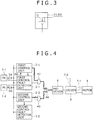
- Diodes D1, D2 may be configured as a MOSFET as shown in Fig. 3 , which allows a forward voltage drop to be reduced.
- gate control enables the arrangement to respond to a fault mode in which the output voltage of the power supply units 1-1, 1-2 is higher than a specified level.
- a third embodiment represents an arrangement that includes, as shown in Fig. 4 , a first control unit 2-1 (a master control unit) and a second control unit 2-2 (a slave control unit) that employs a control method that is simpler than that of the first control unit 2-1 to thereby make a circuit scale small and reduce power consumption, the first control unit 2-1 being switched to the second control unit 2-2.
- a first control unit 2-1 a master control unit
- a second control unit 2-2 a slave control unit
- Power supply units 1-1, 1-2 supply power to the first control unit 2-1, the second control unit 2-2, a first control fault detector unit 3-1, and a second control fault detector unit 3-2 via diodes D1, D2.
- Control signals (three-phase, six lines each for the upper and lower arms) from the first control unit 2-1 and the second control unit 2-2 are output to a pre-driver 5 via AND gates 42, 43 and an OR gate 44. Then, a driver 6 eventually drives a motor 8.
- the first control fault detector unit 3-1 diagnoses the first control unit 2-1 and the power supply units 1-1, 1-2 to determine whether each is operational. When all are fully operational, the output is turned ON, so that the control signal from the first control unit 2-1 is output to the pre-driver 5 via the AND gate 42 and the OR gate 44.
- the second control fault detector unit 3-2 diagnoses the first control unit 2-1, the second control unit 2-2, and the power supply units 1-1, 1-2 to determine whether each is operational. When any one of the first control unit 2-1 and the power supply units 1-1, 1-2 is faulty and the second control unit 2-2 is operational, the output is turned ON to thereby output the control signal from the second control unit 2-2 to the pre-driver 5 via the AND gate 43 and the OR gate 44.
- the above-described embodiment includes the second control unit 2-2, which achieves an electronic control apparatus that can respond to not only a fault of the first control unit 2-1, but also a fault of the power supply units 1-1, 1-2.
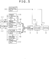
- a fourth embodiment represents an arrangement that includes, as shown in Fig. 5 , an ECU fault detector unit 3-3 that controls a main relay 7-0 and a phase output relay 7-1.
- the ECU fault detector unit 3-3 When either a control signal from a first control unit 2-1 or a control signal from a second control unit 2-2 is normal, the ECU fault detector unit 3-3 turns ON the main relay 7-0 to supply power to a driver 6 and turns ON the phase output relay 7-1 to thereby supply the output to, and drive, a motor 8.
- the main relay 7-0 is turned OFF to shut down the power supply to the driver 6 and the phase output relay 7-1 is turned OFF to cut off the output, thereby de-energizing the motor 8.
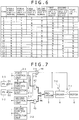
- Fig. 6 is a table illustrating operating states of different parts during a faulty condition.
- the power supply units 1-1, 1-2, the first control unit 2-1, and the second control unit 2-2 are all normal (Y), so that the control signal output from the first control unit 2-1 is selected (first control unit 2-1 output select (Y)) and the main relay 7-0 and the phase output relay 7-1 are turned ON (Y), thus causing the driver 6 to drive the motor 8.
- the second control unit 2-2 is faulty (N); however, the first control unit 2-1 is fully operational, so that the control signal output from the first control unit 2-1 is selected (first control unit 2-1 output select (Y)), the main relay 7-0 and the phase output relay 7-1 are turned ON (Y), and the motor 8 is driven by the driver 6.
- the first control unit 2-1 is faulty (N), so that the control signal output from the second control unit 2-2 is selected (second control unit 2-2 output select (Y) and first control unit 2-1 output select (N)), the main relay 7-0 and the phase output relay 7-1 are turned ON, and the motor 8 is driven by the driver 6.
- both the first control unit 2-1 and the second control unit 2-2 are faulty (N) and thus no normal control signal can be obtained.
- the main relay 7-0 and the phase output relay 7-1 are then turned OFF and drive of the motor 8 by the driver 6 is stopped.
- the power supply unit 1-2 is faulty (N) electric power for operating the first control unit 2-1 cannot be supplied, so that the control signal output from the second control unit 2-2 is selected (second control unit 2-2 output select (Y) and first control unit 2-1 output select (N)), the main relay 7-0 and the phase output relay 7-1 are turned ON, and the motor 8 is driven by the driver 6.
- both the power supply unit 1-2 and the second control unit 2-2 are faulty (N) and electric power required for operating the first control unit 2-1 cannot be supplied.
- Neither the first control unit 2-1 nor the second control unit 2-2 can then provide normal control signals, so that the main relay 7-0 and the phase output relay 7-1 are turned OFF and drive of the motor 8 by the driver 6 is stopped.
- both the power supply unit 1-2 and the first control unit 2-1 are faulty (N) and electric power required for operating the first control unit 2-1 cannot be supplied, so that the first control unit 2-1 is unable to operate properly.
- the control signal output from the second control unit 2-2 is thus selected (second control unit 2-2 output select (Y)), the main relay 7-0 and the phase output relay 7-1 are turned ON, and the motor 8 is driven by the driver 6.
- the power supply unit 1-2, the first control unit 2-1, and the second control unit 2-2 are faulty (N) and no normal control signals can be obtained from the first control unit 2-1 or the second control unit 2-2.
- the main relay 7-0 and the phase output relay 7-1 are thus turned OFF and drive of the motor 8 by the driver 6 is stopped.
- both the power supply unit 1-1 and the second control unit 2-2 are faulty (N) and electric power required for operating the first control unit 2-1 cannot be supplied.
- Neither the first control unit 2-1 nor the second control unit 2-2 can then provide normal control signals, so that the main relay 7-0 and the phase output relay 7-1 are turned OFF and drive of the motor 8 by the driver 6 is stopped.
- both the power supply unit 1-1 and the first control unit 2-1 are faulty and electric power required for operating the first control unit 2-1 cannot be supplied, so that the first control unit 2-1 is unable to operate properly.
- the control signal output from the second control unit 2-2 is thus selected (second control unit 2-2 output select (Y)), the main relay 7-0 and the phase output relay 7-1 are turned ON, and the motor 8 is driven by the driver 6.
- the power supply unit 1-1, the first control unit 2-1, and the second control unit 2-2 are faulty and no normal control signals can be obtained from the first control unit 2-1 or the second control unit 2-2.
- the main relay 7-0 and the phase output relay 7-1 are thus turned OFF and drive of the motor 8 by the driver 6 is stopped.
- both the power supply unit 1-1 and the power supply unit 1-2 are faulty and power is not supplied to the first control unit 2-1 or the second control unit 2-2. No normal control signals can then be obtained, so that the main relay 7-0 and the phase output relay 7-1 are turned OFF and drive of the motor 8 by the driver 6 is stopped.
- the power supply unit 1-1, the power supply unit 1-2, and the first control unit 2-1 are all faulty and power is not supplied to the first control unit 2-1 or the second control unit 2-2. No normal control signals can then be obtained, so that the main relay 7-0 and the phase output relay 7-1 are turned OFF and drive of the motor 8 by the driver 6 is stopped.
- the power supply unit 1-1, the power supply unit 1-2, the first control unit 2-1, and the second control unit 2-2 are all faulty and power is not supplied to the first control unit 2-1 or the second control unit 2-2. No normal control signals can then be obtained, so that the main relay 7-0 and the phase output relay 7-1 are turned OFF and drive of the motor 8 by the driver 6 is stopped.
- a warning lamp may be turned on to warn that the electronic control apparatus is faulty in cases 2 to 16.
- Fig. 7 shows an embodiment that embodies the ECU fault detector unit 3-3 with an exclusive OR gate 41.
- Outputs from a first control fault detector unit 3-1 and a second control fault detector unit 3-2 are made to serve as inputs to the exclusive OR gate 41 and an output therefrom turns ON a main relay 7-0 and a phase output relay 7-1. If the first control fault detector unit 3-1 and the second control fault detector unit 3-2 are normal, the output (select signal) of either the first control fault detector unit 3-1 or the second control fault detector unit 3-2 turns ON. Otherwise, either the first control fault detector unit 3-1 or the second control fault detector unit 3-2 faulty, or no normal control signals can be obtained from a first control unit 2-1 and a second control unit 2-2. In this case, therefore, the main relay 7-0 and the phase output relay 7-1 are cut off to thereby stop the drive of a motor 8 by a driver 6, thereby safety of the electronic control apparatus can be ensured.
- the exclusive OR gate 41 may be configured using a circuit 42 that incorporates MOS transistors Q1 to Q4 as shown in Fig. 8(a) . This prevents the main relay 7-0 and the phase output relay 7-1 from being left ON as caused by a stuck-at fault of the output of the exclusive OR gate 41.
- Figs. 8(a) and 8(b) are diagrams illustrating an exemplary configuration of the exclusive OR circuit.
- Fig. 8(a) is a circuit diagram and
- Fig. 8(b) is a circuit operation table. Referring to the table shown in Fig. 8(b) , when both ina and inb are Hi, the first control fault detector unit 3-1 and the second control fault detector unit 3-2 are determined to be faulty.
- Fig. 9 shows operations of the system to respond to faults at different parts.
- a fault at a power supply unit 1-1 or a power supply unit 1-2 is detected by the first control fault detector unit 3-1 and, when one is detected, the second control unit 2-2 that consumes less power is selected to allow the operation to continue.
- a fault at the first control unit 2-1 is detected by the first control fault detector unit 3-1 and, when one is detected, the second control unit 2-2 is selected to allow the operation to continue.
- a fault at the second control unit 2-2 is detected by the second control fault detector unit 3-2. If the first control unit 2-1 and the power supply remain operational, the operation is allowed to continue; otherwise, the main relay 7-0 and the phase output relay 7-1 are cut off to thereby stop the drive of the motor 8 by the driver 6, thus achieving safety in the electronic control apparatus.
- a fault at the first control fault detector unit 3-1 or the second control fault detector unit 3-2 is detected by the ECU fault detector unit 3-3 (the exclusive OR gate 41). The main relay 7-0 and the phase output relay 7-1 are then cut off to thereby stop the drive of the motor 8 by the driver 6, thus achieving safety in the electronic control apparatus.
- a fault at the ECU fault detector unit 3-3 (the exclusive OR gate 41) is masked by a fail-safe configuration of Q1 to Q4 shown in Fig. 8(a) .
- the drive of the motor 8 by the driver 6 is then stopped by the main relay 7-0 and the phase output relay 7-1 being cut off, thereby ensuring safety in the electronic control apparatus.
- Fig. 10 shows an embodiment in which power supply units 1-1, 1-2 are connected in series with each other.
- Switching regulators are widely used for reduction in loss involved in a regulator voltage drop.
- the switching regulator includes a large number of components and requires a component that defies easy integration, such as a coil. Consolidating functions thereof, therefore, can better reduce cost, weight, and dimensions because of economies of scale involved.
- Dividing power supplies in parallel with each other as an approach taken by the present invention can invite increased cost, weight, and dimensions.
- a switching regulator is used for the power supply unit 1-1 with which the power supply unit 1-2 including a linear regulator is connected in series.
- the power supply unit 1-2 including the linear regulator has an output of 5.0 V and the input thereof, specifically, the output voltage of the power supply unit 1-1 including the switching regulator is slightly higher than that (e.g. 5.5 V).
- the power supply unit 1-1 including the switching regulator If the power supply unit 1-1 including the switching regulator is faulty, the voltage supplied from the battery bypasses the power supply unit 1-1 and is applied to the power supply unit 1-2. As a result, heat generated at the power supply unit 1-2 increases. Power consumption at a control unit 2 (the first control unit 2-1) is then reduced using the method provided by the present invention and the heat generated at the power supply unit 1-2 is thereby reduced.
- the output from the power supply unit 1-1 bypasses the power supply unit 1-2 and is supplied to the control unit 2 as a load.
- the applied voltage is slightly higher (e.g. 5.5 V) than 5.0 V, so that heat generated at the control unit 2 increases.
- the power consumption of the control unit 2 is then reduced using the method provided by the present invention and the heat generated at the control unit 2 is thereby reduced.
- the output from the power supply unit 1-1 bypasses the power supply unit 1-2 to be supplied to the control unit 2 as a load and, at the same time, the output from the power supply unit 1-1 may be switched to 5.0 V from the voltage slightly higher than 5.0 V (e.g. 5.5 V). In this case, though ripple of the power supplied increases, increase in heat generated at the control unit 2 can be avoided.
- a power supply unit 1-3 may be incorporated to supply power of an even lower voltage required by the control unit 2 (microprocessor core operating power supply).
- the power supply unit 1-3 is formed using a switched capacitor, which is preferable in terms of, for example, efficiency, cost, and dimensions.
- Figs. 12 to 17 show embodiments of methods for separating chips for the present invention achieved using the LSI.
- Fig. 12 is an embodiment in which a first control unit 2-1 is mounted on a first semiconductor chip, a first control fault detector unit 3-1 and a second control unit 2-2 are mounted on a second semiconductor chip, and power supply units 1-1, 1-2, a second control fault detector unit 3-2, AND gates 42, 43, an OR gate 44, and a pre-driver 5 are mounted on a third semiconductor chip.
- the first semiconductor chip is configured with a main microprocessor
- the second semiconductor chip is configured with a sub-microprocessor
- the third semiconductor chip is configured with the LSI, such as an ASIC.
- Fig. 13 is an embodiment in which the first control unit 2-1 and the first control fault detector unit 3-1 are mounted on a first semiconductor chip, the second control unit 2-2 is mounted on a second semiconductor chip, and the power supply units 1-1, 1-2, the second control fault detector unit 3-2, the AND gates 42, 43, the OR gate 44, and the pre-driver 5 are mounted on a third semiconductor chip.
- the first semiconductor chip is configured with a main microprocessor or, in particular, a safety microprocessor having a self-checking function
- the second semiconductor chip is configured with a sub-microprocessor
- the third semiconductor chip is configured with the LSI, such as an ASIC.
- Fig. 14 is an embodiment in which the first control unit 2-1 is mounted on a first semiconductor chip, the first control fault detector unit 3-1 and the second control fault detector unit 3-2 are mounted on a second semiconductor chip, and the power supply units 1-1, 1-2, the second control unit 2-2, the AND gates 42, 43, the OR gate 44, and the pre-driver 5 are mounted on a third semiconductor chip.
- the first semiconductor chip is configured with a main microprocessor
- the second semiconductor chip is configured with a sub-microprocessor
- the third semiconductor chip is configured with the LSI, such as an ASIC.
- Fig. 15 is an embodiment in which the first control unit 2-1 is mounted on a first semiconductor chip, the first control fault detector unit 3-1 is mounted on a second semiconductor chip, and the power supply units 1-1, 1-2, the second control unit 2-2, the second control fault detector unit 3-2, the AND gates 42, 43, the OR gate 44, and the pre-driver 5 are mounted on a third semiconductor chip.
- the first semiconductor chip is configured with a main microprocessor
- the second semiconductor chip is configured with a sub-microprocessor
- the third semiconductor chip is configured with the LSI, such as an ASIC.
- Fig. 16 is an embodiment in which the first control unit 2-1 and the first control fault detector unit 3-1 are mounted on a first semiconductor chip and the power supply units 1-1, 1-2, the second control unit 2-2, the second control fault detector unit 3-2, the AND gates 42, 43, the OR gate 44, and the pre-driver 5 are mounted on a third semiconductor chip.
- the first semiconductor chip is configured with a main microprocessor or, in particular, a safety microprocessor having a self-checking function while the third semiconductor chip is configured with the LSI, such as an ASIC.
- Fig. 17 is an embodiment in which the first control unit 2-1 is mounted on a first semiconductor chip and the power supply units 1-1, 1-2, the first control fault detector unit 3-1, the second control unit 2-2, the second control fault detector unit 3-2, the AND gates 42, 43, the OR gate 44, and the pre-driver 5 are mounted on a third semiconductor chip.
- the first semiconductor chip is configured with a main microprocessor and the third semiconductor chip is configured with the LSI, such as an ASIC.
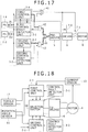
- Fig. 18 is a diagram illustrating a configuration of an electric power steering system according to an aspect of the present invention.
- the electric power steering system applies a steering assist force by a motor 8 to an automotive steering system.
- the electric power steering system includes the motor 8, a rotation angle sensor 11, a torque sensor 12, a current sensor 13, a first control unit 2-1, fault detector units 3-1, 3-2, a second control unit 2-2, a selector switch (selection changeover unit) 18, and a 3 three-phase bridge 6.
- the motor 8 is disposed at, for example, a steering gearbox of the steering system.
- the motor 8 is configured so as to apply the steering assist force to, for example, a steering shaft.
- the rotation angle sensor 11 is mounted on the motor 8, detecting a rotation angle (a magnetic pole position) of the motor 8.
- the torque sensor 12 is mounted on a steering wheel (not shown) of the electric power steering system, detecting steering torque received by the steering wheel.
- the current sensor 13 is mounted on the motor 8, detecting motor current that flows through the motor 8.
- the first control unit 2-1 controls the motor 8 based on the rotation angle detected by the rotation angle sensor 11, the steering torque detected by the torque sensor 12, and the motor current detected by the current sensor 13.
- the first control unit 2-1 includes a microprocessor (MPU) and performs closed-loop control using the motor current.
- MPU microprocessor
- the second control unit 2-2 controls the motor 8 in place of the first control unit 2-1 based on the rotation angle detected by the rotation angle sensor 11 and the steering torque detected by the torque sensor 12.
- the second control unit 2-2 is configured with fixed logic circuitry, performing open-loop control without using the motor current.
- the fault detector units 3-1, 3-2 detect faults in the first control unit 2-1 and the second control unit 2-2, respectively.
- the selector switch 18 selects the output from the first control unit 2-1 to thereby drive the three-phase bridge (driver) 6, thereby driving the motor 8.
- the selector switch 18 selects the output from the second control unit 2-2 to thereby drive the three-phase bridge 6, thereby driving the motor 8.
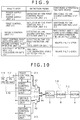
- Fig. 19 is a diagram illustrating a detailed arrangement of the second control unit in Fig. 18 .
- the second control unit 2-2 detects the steering effort on the steering system based on the rotation angle detected by the rotation angle sensor 11 and the steering torque detected by the torque sensor 12, thereby controlling to output PWM current to be output to the motor 8, variable in proportion to the steering effort thus detected.
- the second control unit 2-2 is configured with fixed logic circuitry including an analog circuit and a digital circuit. Referring to Fig. 19 , the second control unit 2-2 includes a coordinate converter section 21, a phase converter section 22, a torque converter section 23, and a multiplier section 24.
- the coordinate converter section 21 subjects a sin ⁇ signal B and a cos ⁇ signal C input from the rotation angle sensor 11 to coordinate conversion into a three-phase sin signal (e.g., U: sin ⁇ , V: sin( ⁇ + 2 ⁇ /3), W: sin( ⁇ + 4 ⁇ /3).
- the phase converter section 22 converts the three-phase sin signal (U, V, W) that has undergone the coordinate conversion at the coordinate converter section 21 to a corresponding digital phase signal (U1, V1, W1).
- the torque converter section 23 coverts an analog torque signal A input from the torque sensor 12 to a corresponding digital torque signal A1.
- the multiplier section 24 multiplies the digital phase signal (U1, V1, W1) by the digital torque signal A1 to thereby calculate drive signals Uo, Vo, Wo of respective phases that serve as motor drive signals, thereby processing to output results to the selector switch 18.
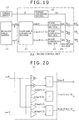
- Fig. 20 is a diagram showing a detailed configuration of the coordinate converter section 21 shown in Fig. 19 .
- the coordinate converter section 21 performs weighting and addition of the sin ⁇ signal and the cos ⁇ signal input from the rotation angle sensor 11 to thereby generate three-phase signals of U, V, and W with a phase difference of 120° from each other.
- Fig. 21 is a diagram showing a specific example of the second control unit.
- the second control unit 2-2 of example 1 is configured such that magnetic pole position information is represented by a three-valued digital signal and target torque information by a three-valued PWM signal.
- the coordinate converter section 21 converts the sin ⁇ signal B and the cos ⁇ signal C input from the rotation angle sensor 11 to three-phase sin signals (U, V, W).
- the resultant three-phase sin signals here have sin waveforms, each of which having a phase advancing 0, 2/3 ⁇ , and 4/3 ⁇ , respectively, from the sin signal (U: sin ⁇ , V: sin( ⁇ + 2 ⁇ /3), W: sin( ⁇ + 4 ⁇ /3)).
- a phase converter section 221 converts the three-phase sin signals (U, V, W) to digital phase signals (U1, V1, W1), each having any of three values of (-1, 0, 1), determined according to the magnitude of the three-phase sin signals.
- a torque converter section 231 converts the analog torque signal A transmitted from the torque sensor 12 to the digital torque signal A1 having a PWM waveform of a duty ratio that is proportional to the magnitude of the torque signal A.
- the multiplier section 24 multiplies the digital phase signals (U1, V1, W1) converted by the phase converter section 221 by the digital torque signal A1 with a PWM waveform converted by the torque converter section 231, to thereby calculate the drive signals Uo, Vo, Wo of three phases and output the resultant as motor control signals.
- the second control unit 2-2 of example 1 converts the three-phase sin signals (U, V, W) to the three-valued digital phase signals (U1, V1, W1) of (-1, 0, 1) using the phase converter section 221. This permits handling of the digital signals for subsequent processing.
- the three-valued digital signals simplify the calculation (multiplication) circuit as compared with a multi-valued digital signal.
- the torque converter section 231 converts the torque signal A to the digital torque signal A1 with a PWM waveform, so that the digital signal can be handled subsequently.
- the binary or three-valued digital signal simplifies the calculation (multiplication) circuit as compared with a multi-valued digital signal.
- the output torque of the motor 8 can be controlled with a simple circuit in proportion to the torque signal (steering effort by a driver) when the first control unit 2-1 is faulty, so that smooth control can continue just as the driver intends.
- the second control unit 2-2 illustrated above is combined with the first control unit 2-1 as shown in Fig. 18 , the first control unit 2-1 and the second control unit 2-2 theoretically achieve the same operation, so that the second control unit 2-2 can perform the function of the first control unit 2-1 should the first control unit 2-1 fail.
- Fig. 22 is a diagram showing another example of the second control unit.
- PWM signals are generated from the three-phase sin signals (U, V, W) generated based on the sin ⁇ signal B and the cos ⁇ signal C input from the rotation angle sensor 11.
- a torque converter section 232 then converts the analog torque signal A transmitted from the torque sensor 12 to three-valued digital torque signals A1, each taking any of three values of (-1, 0, 1) indicating left, middle, or right.
- the multiplier section 24 multiplies the PWM signals (U1, V1, W1) generated from the three-phase sin signals (U, V, W) by the three-valued digital torque signal A1 generated from the torque signal A, to thereby output the drive signals (Uo, Vo, Wo) of three phases.
- the torque converter section 232 converts the torque signal A to the three-valued digital torque signals A1 having three values of (-1, 0, 1). This permits handling of the digital signals for subsequent processing.
- the three-valued, not multi-valued, digital signals simplify the calculation (multiplication) circuit as compared with a multi-valued digital signal.
- the PWM signals (U1, V1, W1) are generated from the three-phase sin signals (U, V, W), so that the digital signals can be handled subsequently.
- the binary or three-valued digital signal simplifies the calculation (multiplication) circuit as compared with a multi-valued digital signal.
- the electric power steering system having the foregoing arrangements includes the first control unit 2-1 and the second control unit 2-2.
- the first control unit 2-1 controls the motor 8 that applies the steering assist force to the automotive steering system based on the motor current of the motor 8, the rotation angle of the motor 8, and the steering torque.
- the second control unit 2-2 controls the motor 8 in place of the first control unit 2-1 when a fault occurs in the first control unit 2-1, based on the rotation angle of the motor 8 and the steering torque.
- the first control unit 2-1 performs the closed-loop control that uses the motor current.
- the second control unit 2-2 performs the open-loop control that does not use the motor current.
- the motor output torque can be smoothly controlled according to the magnetic pole position of the motor 8 with a simple circuit, which allows motor control with small torque ripple to continue.
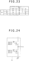
- Fig. 23 is an embodiment of the multiplier section 24 particularly preferable for the embodiment shown in Fig. 21 .
- the column is an input in1, the row is an input in2, and the intersection point is an output value.
- the input in1 takes three values of 1, 0, and -1
- the input in2 takes three values of P (a PWM value proportional to a torque sensor input value (positive)), 0, and -P (a PWM value proportional to a torque sensor input value (negative))
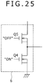
- the output takes P (a PWM output command shown in Fig. 24 ), 0, and L (a lower arm ON command shown in Fig. 25 ).
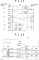
- Exemplary output waveforms according to this embodiment are shown in Figs. 26 and 27 .
- Fig. 26 shows the exemplary output waveforms when the torque sensor output value is positive.
- Fig. 27 shows the exemplary output waveforms when the torque sensor output value is negative.
- Fig. 28 shows an embodiment of the second control fault detector unit 3-2.
- torque sensor signals 12-1, 12-2 and magnetic pole position information are binarized and signals Ur, Vr, Wr that permit control signals of three phases Uo, Vo, Wo to turn ON are generated as shown in Fig. 28 .
- a CMP checks whether the corresponding control signal of each phase Uo, Vo, or Wo is turned ON when it is so permitted, thereby diagnosing the second control unit 2-2.
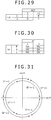
- Fig. 29 shows an embodiment of multipliers 104-1 to 104-2 and
- Fig. 30 shows an embodiment of the CMP.
- a condition that permits the control signal of each phase Uo, Vo, or Wo to turn ON may be obtained directly from the magnetic pole position.
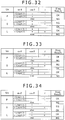
- Fig. 31 is a graph showing a relationship among values of U*, V*, and W* binarized from the U, V, and W signals, magnetic pole positions, and sin ⁇ and cos ⁇ from the rotation angle sensor 11. Results shown in Figs. 32 to 34 are obtained when the second control unit 2-2 is determined to be operational or faulty from values (P, O, L) taken by the control signals of the different phases Uo, Vo, Wo, sin ⁇ and cos ⁇ , and torque ⁇ , using the graph shown in Fig. 31 .
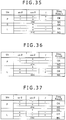
- Fig. 31 is subjected to quadrant determination, specifically, whether the values of sin ⁇ and cos ⁇ are determined to be positive or negative, to obtain results shown in Figs. 35 to 37 .
- Fig. 38 is an embodiment in which the present invention is applied to an electric power steering system.
- the motor 8 driven by the driver 6 applies steering torque to a shaft 9 and a steering function 14 of a steering wheel 10 to thereby assist a manual steering effort applied to the steering wheel 10.
- outputs 12-1, 12-2 of a torque sensor 12 mounted on the shaft 9, outputs 11-1, 11-2 of a rotation angle sensor 11, and a measured value of a current sensor 13 are applied to the first control unit 2-1.
- the torque sensor 12 measures the steering effort applied to the steering wheel 10 and the motor 8 is controlled so as to output torque corresponding to the measured steering effort.
- the manual steering effort applied to the steering wheel 10 is thereby assisted.
- the embodiment allows the steering assist operation to continue when a fault occurs without inviting an increase in the number of hardware devices. If a correct operation is not ensured, steering assist through the motor 8 is properly stopped to thereby ensure safety.
- the electronic control apparatus described heretofore allows the electronic control apparatus to continue operating without inviting an increase in the number of hardware devices even when a fault occurs. If a correct operation is not ensured, the operation is properly stopped to thereby ensure safety.
Landscapes
- Engineering & Computer Science (AREA)
- Mechanical Engineering (AREA)
- Chemical & Material Sciences (AREA)
- Combustion & Propulsion (AREA)
- Transportation (AREA)
- Power Steering Mechanism (AREA)
- Steering Control In Accordance With Driving Conditions (AREA)
- Power Engineering (AREA)
- Control Of Electric Motors In General (AREA)
Claims (10)
- Appareil de commande électronique comprenant :une unité de commande (2) ; une pluralité d'unités d'alimentation de puissance (1-1, 1-2) pour alimenter l'unité de commande (2) avec une puissance ; etune unité de détection de défaut d'alimentation de puissance (3) pour détecter un défaut dans la pluralité d'unités d'alimentation de puissance (1-1, 1-2),dans lequel l'unité de commande (2) fonctionne dans un mode normal sur la puissance électrique alimentée depuis la pluralité d'unités d'alimentation de puissance (1-1, 1-2) si aucune de la pluralité d'unités d'alimentation de puissance (1-1, 1-2) est en défaut ;caractérisé en ce que si l'une au moins de la pluralité d'unités d'alimentation de puissance (1-1, 1-2) est en défaut, l'unité de commande (2) fonctionne dans un mode d'économie d'énergie dans lequel une puissance moindre est consommée sur la puissance électrique alimentée depuis l'unité d'alimentation de puissance qui reste entièrement opérationnelle ;dans lequel l'unité de commande (2) inclut un moyen de réduction de cadence (2a) qui réduit la fréquence de la cadence de fonctionnement d'un processeur constituant l'unité de commande (2) dans le mode d'économie d'énergie.
- Appareil de commande électronique selon la revendication 1, dans lequel la pluralité d'unités d'alimentation de puissance (1-1, 1-2) comprend un régulateur de tension connecté à une batterie ou à un générateur, le régulateur de tension étant destiné à alimenter une tension prédéterminée.
- Appareil de commande électronique selon la revendication 1,
dans lequel l'unité de commande (2) inclut un moyen de changement de paramètre (2b) qui change un paramètre de commande au niveau de l'unité de commande (3) dans le mode d'économie d'énergie. - Appareil de commande électronique selon la revendication 1,
dans lequel l'unité de commande (2) inclut une unité de commande maître (2-1) et une unité de commande asservie (2-2), l'unité de commande maître (2-1) étant amenée à fonctionner dans le mode normal et l'unité de commande asservie étant amenée à fonctionner dans le mode d'économie d'énergie. - Appareil de commande électronique selon la revendication 4,
dans lequel l'unité de commande asservie (2-2) comporte un circuit à une échelle plus petite que celle de l'unité de commande maître (2-1). - Appareil de commande électronique selon la revendication 4,
dans lequel l'unité de commande asservie (2-2) est configurée avec des circuits logiques fixes. - Appareil de commande électronique selon la revendication 4,
dans lequel l'unité de commande asservie (2-2) est amenée à fonctionner quand un défaut se produit dans l'unité de commande maître (2-1) avec toutes celles des unités de la pluralité d'unités d'alimentation de puissance (1-1, 1-2) qui restent entièrement opérationnelles. - Appareil de commande électronique selon la revendication 1,
dans lequel la pluralité d'unités d'alimentation de puissance (1-1, 1-2) sont connectées en parallèle les unes avec les autres, en partageant un courant de sortie les unes avec les autres. - Appareil de commande électronique selon la revendication 1,
dans lequel la pluralité d'unités d'alimentation de puissance (1-1, 1-2) sont connectées en série les unes avec les autres, en partageant une chute de tension les unes avec les autres. - Appareil de commande pour direction assistée électrique incorporant l'appareil de commande électronique selon la revendication 1,
dans lequel l'unité de commande (2) fonctionne avec, à titre d'entrée qui lui sont appliquées, une sortie provenant d'un capteur de couple (12) disposé sur un arbre, une sortie provenant d'un capteur d'angle de rotation (11) disposé concentriquement avec un moteur (8), et une valeur mesurée par un capteur de courant (13) ; et
dans lequel un moteur piloté par l'unité de commande (2) applique un couple de direction à un volant de direction, un arbre, et une fonction de direction.
Applications Claiming Priority (2)
| Application Number | Priority Date | Filing Date | Title |
|---|---|---|---|
| JP2010139566 | 2010-06-18 | ||
| PCT/JP2011/063725 WO2011158876A1 (fr) | 2010-06-18 | 2011-06-15 | Dispositif de commande électronique |
Publications (3)
| Publication Number | Publication Date |
|---|---|
| EP2583879A1 EP2583879A1 (fr) | 2013-04-24 |
| EP2583879A4 EP2583879A4 (fr) | 2018-06-27 |
| EP2583879B1 true EP2583879B1 (fr) | 2020-06-24 |
Family
ID=45348273
Family Applications (1)
| Application Number | Title | Priority Date | Filing Date |
|---|---|---|---|
| EP11795780.3A Active EP2583879B1 (fr) | 2010-06-18 | 2011-06-15 | Dispositif de commande électronique |
Country Status (4)
| Country | Link |
|---|---|
| US (2) | US8738232B2 (fr) |
| EP (1) | EP2583879B1 (fr) |
| JP (2) | JP5563077B2 (fr) |
| WO (1) | WO2011158876A1 (fr) |
Families Citing this family (24)
| Publication number | Priority date | Publication date | Assignee | Title |
|---|---|---|---|---|
| JP5569273B2 (ja) * | 2010-09-07 | 2014-08-13 | 株式会社ジェイテクト | 電動パワーステアリング装置 |
| WO2012144069A1 (fr) * | 2011-04-22 | 2012-10-26 | 三菱電機株式会社 | Dispositif de direction assistée électrique |
| DE102012200181B4 (de) * | 2012-01-09 | 2024-06-20 | Robert Bosch Gmbh | Steuereinrichtungen an Bord des Kraftfahrzeugs |
| JP5622054B2 (ja) * | 2012-03-12 | 2014-11-12 | 株式会社デンソー | 車載電源システム |
| US9740178B2 (en) * | 2013-03-14 | 2017-08-22 | GM Global Technology Operations LLC | Primary controller designation in fault tolerant systems |
| US9139223B2 (en) * | 2013-05-23 | 2015-09-22 | Caterpillar Inc. | Managing steering with short from battery to ground |
| GB201310193D0 (en) * | 2013-06-07 | 2013-07-24 | Trw Ltd | Motor control circuit |
| CN104283485B (zh) * | 2013-07-09 | 2017-10-31 | 比亚迪股份有限公司 | 电动汽车及其电机控制系统和控制方法 |
| KR101453985B1 (ko) * | 2014-03-12 | 2014-10-28 | 콘티넨탈 오토모티브 시스템 주식회사 | 차량용 전자제어회로 |
| JP6349989B2 (ja) * | 2014-06-11 | 2018-07-04 | 株式会社ジェイテクト | モータ制御装置及びステアリング装置 |
| US10392049B2 (en) | 2015-04-08 | 2019-08-27 | Hitachi Automotive Systems, Ltd. | Power steering device and control device for on-board device |
| DE102015115123A1 (de) * | 2015-09-09 | 2017-03-09 | Robert Bosch Automotive Steering Gmbh | Vorrichtung zum Betreiben eines Servolenksystems, Servolenksystem |
| JP6679861B2 (ja) * | 2015-09-15 | 2020-04-15 | 株式会社デンソー | センサ装置、および、これを用いた電動パワーステアリング装置 |
| WO2018173561A1 (fr) * | 2017-03-23 | 2018-09-27 | 日立オートモティブシステムズ株式会社 | Dispositif de commande de véhicule |
| US11148819B2 (en) | 2019-01-23 | 2021-10-19 | H55 Sa | Battery module for electrically-driven aircraft |
| US10854866B2 (en) | 2019-04-08 | 2020-12-01 | H55 Sa | Power supply storage and fire management in electrically-driven aircraft |
| US10479223B2 (en) | 2018-01-25 | 2019-11-19 | H55 Sa | Construction and operation of electric or hybrid aircraft |
| CH715770A1 (fr) * | 2019-01-23 | 2020-07-31 | H55 Sa | Système d'entraînement électrique pour un avion à propulsion électrique. |
| US11065979B1 (en) | 2017-04-05 | 2021-07-20 | H55 Sa | Aircraft monitoring system and method for electric or hybrid aircrafts |
| US11063323B2 (en) | 2019-01-23 | 2021-07-13 | H55 Sa | Battery module for electrically-driven aircraft |
| US11031804B2 (en) * | 2017-11-06 | 2021-06-08 | Nxp B.V. | Power controller |
| DE102018114828B3 (de) * | 2018-06-20 | 2019-07-25 | Thyssenkrupp Ag | Kraftfahrzeuglenkung mit einem redundant ausgelegten Steuergerät |
| KR102637909B1 (ko) * | 2019-01-23 | 2024-02-19 | 에이치엘만도 주식회사 | 전동식 파워 스티어링 시스템의 리던던시 회로 |
| JP6925483B1 (ja) * | 2020-06-17 | 2021-08-25 | 三菱電機株式会社 | 車両制御装置 |
Family Cites Families (22)
| Publication number | Priority date | Publication date | Assignee | Title |
|---|---|---|---|---|
| JPS6080969A (ja) * | 1983-10-13 | 1985-05-08 | Nissan Motor Co Ltd | パワ−ステアリング装置 |
| JPH06127408A (ja) * | 1992-10-16 | 1994-05-10 | Aisin Seiki Co Ltd | 後輪操舵装置 |
| JPH06298105A (ja) * | 1993-04-15 | 1994-10-25 | Nippondenso Co Ltd | 後輪操舵装置の制御システム |
| CN1127873C (zh) * | 1997-10-24 | 2003-11-12 | 皇家菲利浦电子有限公司 | 一种电池驱动的通讯设备 |
| US6862676B1 (en) * | 2001-01-16 | 2005-03-01 | Sun Microsystems, Inc. | Superscalar processor having content addressable memory structures for determining dependencies |
| JP3925196B2 (ja) * | 2001-12-27 | 2007-06-06 | 株式会社デンソー | 車両用電子機器 |
| JP4521258B2 (ja) | 2004-01-28 | 2010-08-11 | 日立オートモティブシステムズ株式会社 | レゾルバ/デジタル変換器及びこれを用いた制御システム |
| EP2177413B1 (fr) * | 2004-07-15 | 2015-02-25 | Hitachi, Ltd. | Système de commande de véhicule |
| CA2537329C (fr) * | 2005-03-07 | 2011-01-25 | Honda Motor Co., Ltd. | Structure d'agencement de capteur d'angle de braquage de la roue avant d'un vehicule pour usage routier intensif |
| JP4816293B2 (ja) * | 2006-07-11 | 2011-11-16 | トヨタ自動車株式会社 | 電動パワーステアリング装置 |
| AU2007350363B2 (en) * | 2007-03-30 | 2011-12-08 | Intivation Holding B.V. | Pulse width controlled DC-DC converter having pulse width period control for influencing power consumption |
| JP2008253045A (ja) | 2007-03-30 | 2008-10-16 | Showa Corp | 電動パワーステアリング装置のモータ制御装置 |
| JP2009029196A (ja) | 2007-07-25 | 2009-02-12 | Denso Corp | 電動パワーステアリング装置 |
| JP4978792B2 (ja) | 2007-09-06 | 2012-07-18 | 株式会社デンソー | 電動パワーステアリング装置 |
| JP2009067077A (ja) * | 2007-09-10 | 2009-04-02 | Denso Corp | 電動パワーステアリング装置 |
| JP5125482B2 (ja) | 2007-12-21 | 2013-01-23 | 株式会社Jvcケンウッド | 受信機、制御方法及びプログラム |
| US8437915B2 (en) * | 2008-01-30 | 2013-05-07 | Mitsubishi Electric Corporation | Steering controller |
| JP5401934B2 (ja) * | 2008-06-16 | 2014-01-29 | 株式会社ジェイテクト | 電動パワーステアリング装置 |
| US20100001586A1 (en) * | 2008-07-02 | 2010-01-07 | Tellabs Vienna, Inc. | Method and system for managing backup power |
| JP2010139566A (ja) | 2008-12-09 | 2010-06-24 | Sumitomo Electric Ind Ltd | レンズユニット |
| CN101478435B (zh) * | 2009-01-20 | 2011-01-12 | 杭州华三通信技术有限公司 | 一种堆叠系统的拓扑收集方法和双控制板设备 |
| GB2470192A (en) * | 2009-05-12 | 2010-11-17 | Gm Global Tech Operations Inc | Controlling an active vehicle subsystem |
-
2011
- 2011-06-15 WO PCT/JP2011/063725 patent/WO2011158876A1/fr active Application Filing
- 2011-06-15 EP EP11795780.3A patent/EP2583879B1/fr active Active
- 2011-06-15 US US13/704,864 patent/US8738232B2/en active Active
- 2011-06-15 JP JP2012520476A patent/JP5563077B2/ja active Active
-
2014
- 2014-04-15 US US14/253,264 patent/US9020704B2/en active Active
- 2014-06-11 JP JP2014120164A patent/JP5855167B2/ja active Active
Non-Patent Citations (1)
| Title |
|---|
| None * |
Also Published As
| Publication number | Publication date |
|---|---|
| EP2583879A4 (fr) | 2018-06-27 |
| US20140229074A1 (en) | 2014-08-14 |
| US9020704B2 (en) | 2015-04-28 |
| US8738232B2 (en) | 2014-05-27 |
| US20130090813A1 (en) | 2013-04-11 |
| EP2583879A1 (fr) | 2013-04-24 |
| JP2014193720A (ja) | 2014-10-09 |
| JP5563077B2 (ja) | 2014-07-30 |
| JPWO2011158876A1 (ja) | 2013-08-19 |
| JP5855167B2 (ja) | 2016-02-09 |
| WO2011158876A1 (fr) | 2011-12-22 |
Similar Documents
| Publication | Publication Date | Title |
|---|---|---|
| EP2583879B1 (fr) | Dispositif de commande électronique | |
| US10097129B2 (en) | Drive controller and drive control method for electric motor | |
| US10177694B2 (en) | Current sensor abnormality diagnosis device | |
| US10243503B2 (en) | Drive controller and drive control method for electric motor | |
| US8660755B2 (en) | Electric power steering system | |
| US9043089B2 (en) | Actuator control apparatus | |
| US20160231142A1 (en) | Motor rotational angle detection device and electric power steering device using motor rotational angle detection device | |
| CN110417314B (zh) | 马达控制装置及电动助力转向装置 | |
| EP3613650B1 (fr) | Appareil de commande de véhicule | |
| JP5833360B2 (ja) | モータ制御装置及び車両用操舵装置 | |
| US11691667B2 (en) | Steering device and steering method | |
| CN109195859B (zh) | 电子控制装置及其动作控制方法 | |
| US9146567B2 (en) | Current control device | |
| EP2950444B1 (fr) | Système de commande de moteur | |
| CN103812414A (zh) | 用于交流电动机的控制装置 | |
| US8767364B2 (en) | Vehicle steering system | |
| US9421998B2 (en) | Method and apparatus for detecting motor error of motor driven power steering | |
| US20210050798A1 (en) | Power conversion device, driving device, and power steering device | |
| JP2005229768A (ja) | ブラシレスモータ駆動装置 | |
| JP2013180661A (ja) | 電子制御装置、異常検出方法 | |
| JP4483522B2 (ja) | 電動パワーステアリング装置及び電力供給システム | |
| JPWO2019220780A1 (ja) | 故障診断方法、電力変換装置、モータモジュールおよび電動パワーステアリング装置 | |
| WO2018056381A1 (fr) | Dispositif d'onduleur biaxial | |
| US20240106264A1 (en) | Power supply apparatus | |
| US20220048560A1 (en) | Steering assist device and method, and steering system |
Legal Events
| Date | Code | Title | Description |
|---|---|---|---|
| PUAI | Public reference made under article 153(3) epc to a published international application that has entered the european phase |
Free format text: ORIGINAL CODE: 0009012 |
|
| 17P | Request for examination filed |
Effective date: 20130118 |
|
| AK | Designated contracting states |
Kind code of ref document: A1 Designated state(s): AL AT BE BG CH CY CZ DE DK EE ES FI FR GB GR HR HU IE IS IT LI LT LU LV MC MK MT NL NO PL PT RO RS SE SI SK SM TR |
|
| DAX | Request for extension of the european patent (deleted) | ||
| RIC1 | Information provided on ipc code assigned before grant |
Ipc: H02J 1/00 20060101ALI20180210BHEP Ipc: B62D 119/00 20060101ALI20180210BHEP Ipc: B62D 113/00 20060101ALI20180210BHEP Ipc: H02P 29/00 20160101ALI20180210BHEP Ipc: B62D 6/08 20060101ALI20180210BHEP Ipc: B60R 16/033 20060101ALI20180210BHEP Ipc: B62D 5/04 20060101AFI20180210BHEP |
|
| RA4 | Supplementary search report drawn up and despatched (corrected) |
Effective date: 20180525 |
|
| RIC1 | Information provided on ipc code assigned before grant |
Ipc: B62D 5/04 20060101AFI20180518BHEP Ipc: B62D 119/00 20060101ALI20180518BHEP Ipc: H02P 29/00 20060101ALI20180518BHEP Ipc: H02J 1/00 20060101ALI20180518BHEP Ipc: B62D 6/08 20060101ALI20180518BHEP Ipc: B60R 16/033 20060101ALI20180518BHEP Ipc: B62D 113/00 20060101ALI20180518BHEP |
|
| GRAP | Despatch of communication of intention to grant a patent |
Free format text: ORIGINAL CODE: EPIDOSNIGR1 |
|
| STAA | Information on the status of an ep patent application or granted ep patent |
Free format text: STATUS: GRANT OF PATENT IS INTENDED |
|
| INTG | Intention to grant announced |
Effective date: 20200311 |
|
| GRAS | Grant fee paid |
Free format text: ORIGINAL CODE: EPIDOSNIGR3 |
|
| GRAA | (expected) grant |
Free format text: ORIGINAL CODE: 0009210 |
|
| STAA | Information on the status of an ep patent application or granted ep patent |
Free format text: STATUS: THE PATENT HAS BEEN GRANTED |
|
| RIN1 | Information on inventor provided before grant (corrected) |
Inventor name: HONDA, KEISUKE Inventor name: UEHARA, ATSUSHI Inventor name: KOSEKI, TOMONOBU Inventor name: KANEKAWA, NOBUYASU Inventor name: KOBAYASHI, RYOICHI |
|
| AK | Designated contracting states |
Kind code of ref document: B1 Designated state(s): AL AT BE BG CH CY CZ DE DK EE ES FI FR GB GR HR HU IE IS IT LI LT LU LV MC MK MT NL NO PL PT RO RS SE SI SK SM TR |
|
| REG | Reference to a national code |
Ref country code: GB Ref legal event code: FG4D |
|
| REG | Reference to a national code |
Ref country code: CH Ref legal event code: EP |
|
| REG | Reference to a national code |
Ref country code: AT Ref legal event code: REF Ref document number: 1283609 Country of ref document: AT Kind code of ref document: T Effective date: 20200715 |
|
| REG | Reference to a national code |
Ref country code: DE Ref legal event code: R096 Ref document number: 602011067470 Country of ref document: DE |
|
| REG | Reference to a national code |
Ref country code: IE Ref legal event code: FG4D |
|
| PG25 | Lapsed in a contracting state [announced via postgrant information from national office to epo] |
Ref country code: FI Free format text: LAPSE BECAUSE OF FAILURE TO SUBMIT A TRANSLATION OF THE DESCRIPTION OR TO PAY THE FEE WITHIN THE PRESCRIBED TIME-LIMIT Effective date: 20200624 Ref country code: NO Free format text: LAPSE BECAUSE OF FAILURE TO SUBMIT A TRANSLATION OF THE DESCRIPTION OR TO PAY THE FEE WITHIN THE PRESCRIBED TIME-LIMIT Effective date: 20200924 Ref country code: LT Free format text: LAPSE BECAUSE OF FAILURE TO SUBMIT A TRANSLATION OF THE DESCRIPTION OR TO PAY THE FEE WITHIN THE PRESCRIBED TIME-LIMIT Effective date: 20200624 Ref country code: GR Free format text: LAPSE BECAUSE OF FAILURE TO SUBMIT A TRANSLATION OF THE DESCRIPTION OR TO PAY THE FEE WITHIN THE PRESCRIBED TIME-LIMIT Effective date: 20200925 Ref country code: SE Free format text: LAPSE BECAUSE OF FAILURE TO SUBMIT A TRANSLATION OF THE DESCRIPTION OR TO PAY THE FEE WITHIN THE PRESCRIBED TIME-LIMIT Effective date: 20200624 |
|
| REG | Reference to a national code |
Ref country code: LT Ref legal event code: MG4D |
|
| PG25 | Lapsed in a contracting state [announced via postgrant information from national office to epo] |
Ref country code: BG Free format text: LAPSE BECAUSE OF FAILURE TO SUBMIT A TRANSLATION OF THE DESCRIPTION OR TO PAY THE FEE WITHIN THE PRESCRIBED TIME-LIMIT Effective date: 20200924 Ref country code: HR Free format text: LAPSE BECAUSE OF FAILURE TO SUBMIT A TRANSLATION OF THE DESCRIPTION OR TO PAY THE FEE WITHIN THE PRESCRIBED TIME-LIMIT Effective date: 20200624 Ref country code: LV Free format text: LAPSE BECAUSE OF FAILURE TO SUBMIT A TRANSLATION OF THE DESCRIPTION OR TO PAY THE FEE WITHIN THE PRESCRIBED TIME-LIMIT Effective date: 20200624 Ref country code: RS Free format text: LAPSE BECAUSE OF FAILURE TO SUBMIT A TRANSLATION OF THE DESCRIPTION OR TO PAY THE FEE WITHIN THE PRESCRIBED TIME-LIMIT Effective date: 20200624 |
|
| REG | Reference to a national code |
Ref country code: NL Ref legal event code: MP Effective date: 20200624 |
|
| REG | Reference to a national code |
Ref country code: AT Ref legal event code: MK05 Ref document number: 1283609 Country of ref document: AT Kind code of ref document: T Effective date: 20200624 |
|
| PG25 | Lapsed in a contracting state [announced via postgrant information from national office to epo] |
Ref country code: AL Free format text: LAPSE BECAUSE OF FAILURE TO SUBMIT A TRANSLATION OF THE DESCRIPTION OR TO PAY THE FEE WITHIN THE PRESCRIBED TIME-LIMIT Effective date: 20200624 Ref country code: NL Free format text: LAPSE BECAUSE OF FAILURE TO SUBMIT A TRANSLATION OF THE DESCRIPTION OR TO PAY THE FEE WITHIN THE PRESCRIBED TIME-LIMIT Effective date: 20200624 |
|
| PG25 | Lapsed in a contracting state [announced via postgrant information from national office to epo] |
Ref country code: ES Free format text: LAPSE BECAUSE OF FAILURE TO SUBMIT A TRANSLATION OF THE DESCRIPTION OR TO PAY THE FEE WITHIN THE PRESCRIBED TIME-LIMIT Effective date: 20200624 Ref country code: PT Free format text: LAPSE BECAUSE OF FAILURE TO SUBMIT A TRANSLATION OF THE DESCRIPTION OR TO PAY THE FEE WITHIN THE PRESCRIBED TIME-LIMIT Effective date: 20201026 Ref country code: RO Free format text: LAPSE BECAUSE OF FAILURE TO SUBMIT A TRANSLATION OF THE DESCRIPTION OR TO PAY THE FEE WITHIN THE PRESCRIBED TIME-LIMIT Effective date: 20200624 Ref country code: IT Free format text: LAPSE BECAUSE OF FAILURE TO SUBMIT A TRANSLATION OF THE DESCRIPTION OR TO PAY THE FEE WITHIN THE PRESCRIBED TIME-LIMIT Effective date: 20200624 Ref country code: CZ Free format text: LAPSE BECAUSE OF FAILURE TO SUBMIT A TRANSLATION OF THE DESCRIPTION OR TO PAY THE FEE WITHIN THE PRESCRIBED TIME-LIMIT Effective date: 20200624 Ref country code: SM Free format text: LAPSE BECAUSE OF FAILURE TO SUBMIT A TRANSLATION OF THE DESCRIPTION OR TO PAY THE FEE WITHIN THE PRESCRIBED TIME-LIMIT Effective date: 20200624 Ref country code: EE Free format text: LAPSE BECAUSE OF FAILURE TO SUBMIT A TRANSLATION OF THE DESCRIPTION OR TO PAY THE FEE WITHIN THE PRESCRIBED TIME-LIMIT Effective date: 20200624 Ref country code: AT Free format text: LAPSE BECAUSE OF FAILURE TO SUBMIT A TRANSLATION OF THE DESCRIPTION OR TO PAY THE FEE WITHIN THE PRESCRIBED TIME-LIMIT Effective date: 20200624 |
|
| PG25 | Lapsed in a contracting state [announced via postgrant information from national office to epo] |
Ref country code: SK Free format text: LAPSE BECAUSE OF FAILURE TO SUBMIT A TRANSLATION OF THE DESCRIPTION OR TO PAY THE FEE WITHIN THE PRESCRIBED TIME-LIMIT Effective date: 20200624 Ref country code: PL Free format text: LAPSE BECAUSE OF FAILURE TO SUBMIT A TRANSLATION OF THE DESCRIPTION OR TO PAY THE FEE WITHIN THE PRESCRIBED TIME-LIMIT Effective date: 20200624 Ref country code: IS Free format text: LAPSE BECAUSE OF FAILURE TO SUBMIT A TRANSLATION OF THE DESCRIPTION OR TO PAY THE FEE WITHIN THE PRESCRIBED TIME-LIMIT Effective date: 20201024 |
|
| REG | Reference to a national code |
Ref country code: DE Ref legal event code: R082 Ref document number: 602011067470 Country of ref document: DE Representative=s name: MERH-IP MATIAS ERNY REICHL HOFFMANN PATENTANWA, DE Ref country code: DE Ref legal event code: R081 Ref document number: 602011067470 Country of ref document: DE Owner name: HITACHI ASTEMO, LTD., HITACHINAKA-SHI, JP Free format text: FORMER OWNER: HITACHI AUTOMOTIVE SYSTEMS, LTD., HITACHINAKA-SHI, IBARAKI, JP |
|
| REG | Reference to a national code |
Ref country code: DE Ref legal event code: R097 Ref document number: 602011067470 Country of ref document: DE |
|
| PG25 | Lapsed in a contracting state [announced via postgrant information from national office to epo] |
Ref country code: DK Free format text: LAPSE BECAUSE OF FAILURE TO SUBMIT A TRANSLATION OF THE DESCRIPTION OR TO PAY THE FEE WITHIN THE PRESCRIBED TIME-LIMIT Effective date: 20200624 |
|
| PLBE | No opposition filed within time limit |
Free format text: ORIGINAL CODE: 0009261 |
|
| STAA | Information on the status of an ep patent application or granted ep patent |
Free format text: STATUS: NO OPPOSITION FILED WITHIN TIME LIMIT |
|
| 26N | No opposition filed |
Effective date: 20210325 |
|
| PG25 | Lapsed in a contracting state [announced via postgrant information from national office to epo] |
Ref country code: SI Free format text: LAPSE BECAUSE OF FAILURE TO SUBMIT A TRANSLATION OF THE DESCRIPTION OR TO PAY THE FEE WITHIN THE PRESCRIBED TIME-LIMIT Effective date: 20200624 |
|
| PG25 | Lapsed in a contracting state [announced via postgrant information from national office to epo] |
Ref country code: MC Free format text: LAPSE BECAUSE OF FAILURE TO SUBMIT A TRANSLATION OF THE DESCRIPTION OR TO PAY THE FEE WITHIN THE PRESCRIBED TIME-LIMIT Effective date: 20200624 |
|
| REG | Reference to a national code |
Ref country code: CH Ref legal event code: PL |
|
| GBPC | Gb: european patent ceased through non-payment of renewal fee |
Effective date: 20210615 |
|
| REG | Reference to a national code |
Ref country code: BE Ref legal event code: MM Effective date: 20210630 |
|
| PG25 | Lapsed in a contracting state [announced via postgrant information from national office to epo] |
Ref country code: LU Free format text: LAPSE BECAUSE OF NON-PAYMENT OF DUE FEES Effective date: 20210615 |
|
| PG25 | Lapsed in a contracting state [announced via postgrant information from national office to epo] |
Ref country code: LI Free format text: LAPSE BECAUSE OF NON-PAYMENT OF DUE FEES Effective date: 20210630 Ref country code: IE Free format text: LAPSE BECAUSE OF NON-PAYMENT OF DUE FEES Effective date: 20210615 Ref country code: GB Free format text: LAPSE BECAUSE OF NON-PAYMENT OF DUE FEES Effective date: 20210615 Ref country code: CH Free format text: LAPSE BECAUSE OF NON-PAYMENT OF DUE FEES Effective date: 20210630 |
|
| PG25 | Lapsed in a contracting state [announced via postgrant information from national office to epo] |
Ref country code: FR Free format text: LAPSE BECAUSE OF NON-PAYMENT OF DUE FEES Effective date: 20210630 |
|
| PG25 | Lapsed in a contracting state [announced via postgrant information from national office to epo] |
Ref country code: BE Free format text: LAPSE BECAUSE OF NON-PAYMENT OF DUE FEES Effective date: 20210630 |
|
| PG25 | Lapsed in a contracting state [announced via postgrant information from national office to epo] |
Ref country code: HU Free format text: LAPSE BECAUSE OF FAILURE TO SUBMIT A TRANSLATION OF THE DESCRIPTION OR TO PAY THE FEE WITHIN THE PRESCRIBED TIME-LIMIT; INVALID AB INITIO Effective date: 20110615 Ref country code: CY Free format text: LAPSE BECAUSE OF FAILURE TO SUBMIT A TRANSLATION OF THE DESCRIPTION OR TO PAY THE FEE WITHIN THE PRESCRIBED TIME-LIMIT Effective date: 20200624 |
|
| PG25 | Lapsed in a contracting state [announced via postgrant information from national office to epo] |
Ref country code: MK Free format text: LAPSE BECAUSE OF FAILURE TO SUBMIT A TRANSLATION OF THE DESCRIPTION OR TO PAY THE FEE WITHIN THE PRESCRIBED TIME-LIMIT Effective date: 20200624 |
|
| PGFP | Annual fee paid to national office [announced via postgrant information from national office to epo] |
Ref country code: DE Payment date: 20240502 Year of fee payment: 14 |
|
| PG25 | Lapsed in a contracting state [announced via postgrant information from national office to epo] |
Ref country code: MT Free format text: LAPSE BECAUSE OF FAILURE TO SUBMIT A TRANSLATION OF THE DESCRIPTION OR TO PAY THE FEE WITHIN THE PRESCRIBED TIME-LIMIT Effective date: 20200624 |