EP2581697A2 - Munitionsbehälter - Google Patents
Munitionsbehälter Download PDFInfo
- Publication number
- EP2581697A2 EP2581697A2 EP12187561.1A EP12187561A EP2581697A2 EP 2581697 A2 EP2581697 A2 EP 2581697A2 EP 12187561 A EP12187561 A EP 12187561A EP 2581697 A2 EP2581697 A2 EP 2581697A2
- Authority
- EP
- European Patent Office
- Prior art keywords
- ammunition
- ammunition container
- guide element
- guide
- container according
- Prior art date
- Legal status (The legal status is an assumption and is not a legal conclusion. Google has not performed a legal analysis and makes no representation as to the accuracy of the status listed.)
- Granted
Links
- 230000006641 stabilisation Effects 0.000 claims abstract description 5
- 238000011105 stabilization Methods 0.000 claims abstract description 5
- 230000006978 adaptation Effects 0.000 claims description 4
- 239000010410 layer Substances 0.000 description 13
- 239000002184 metal Substances 0.000 description 3
- 239000000463 material Substances 0.000 description 2
- 241000270295 Serpentes Species 0.000 description 1
- 230000001133 acceleration Effects 0.000 description 1
- 230000000903 blocking effect Effects 0.000 description 1
- 230000001419 dependent effect Effects 0.000 description 1
- 238000011161 development Methods 0.000 description 1
- 230000018109 developmental process Effects 0.000 description 1
- 239000002355 dual-layer Substances 0.000 description 1
- 210000003746 feather Anatomy 0.000 description 1
- 238000012423 maintenance Methods 0.000 description 1
- 230000007257 malfunction Effects 0.000 description 1
- 238000004519 manufacturing process Methods 0.000 description 1
- 230000002035 prolonged effect Effects 0.000 description 1
- 238000009420 retrofitting Methods 0.000 description 1
- 230000000087 stabilizing effect Effects 0.000 description 1
Images

Classifications
-
- F—MECHANICAL ENGINEERING; LIGHTING; HEATING; WEAPONS; BLASTING
- F41—WEAPONS
- F41A—FUNCTIONAL FEATURES OR DETAILS COMMON TO BOTH SMALLARMS AND ORDNANCE, e.g. CANNONS; MOUNTINGS FOR SMALLARMS OR ORDNANCE
- F41A9/00—Feeding or loading of ammunition; Magazines; Guiding means for the extracting of cartridges
- F41A9/61—Magazines
- F41A9/79—Magazines for belted ammunition
-
- F—MECHANICAL ENGINEERING; LIGHTING; HEATING; WEAPONS; BLASTING
- F41—WEAPONS
- F41A—FUNCTIONAL FEATURES OR DETAILS COMMON TO BOTH SMALLARMS AND ORDNANCE, e.g. CANNONS; MOUNTINGS FOR SMALLARMS OR ORDNANCE
- F41A9/00—Feeding or loading of ammunition; Magazines; Guiding means for the extracting of cartridges
- F41A9/29—Feeding of belted ammunition
- F41A9/34—Feeding of belted ammunition from magazines
Definitions
- the invention relates to an ammunition container for receiving an ammunition belt with ammunition.
- Such ammunition containers are known in the art. They are used in particular in connection with weapon systems in which it is important to supply a cartridge-equipped ammunition belt at high speed to a weapon system.
- Such containers usually have the shape of a cuboid with a bottom, a lid and side walls. The width of the floor corresponds to the length of the ammunition to be picked up.
- the ammunition ammunition straps snake into the container or inserted meander-shaped, so that the ammunition belt is arranged layered in individual layers.
- a disadvantage of the known ammunition containers has been found that changes the position of the ammunition in the ammunition container during storage, but especially during transport or movement of the ammunition container, so that the ammunition wedged and therefore be pulled out only with increased effort from the ammunition container can.
- the problem of changes in position occurs in particular when the ammunition container is already partially emptied. As a result, malfunctions occur at the downstream weapon system because the ammunition is no longer supplied smoothly and smoothly.
- the DE 25 44 208 C2 shows an ammunition container with sliding, rod-shaped elements for stabilization, which are guided in translation in opposite guide slots. However, tilting of the bars may occur due to the guidance, as a result of which the functionality may be impeded.
- the invention is based on the prior art, the object to show an ammunition container in which the ammunition is capable of stabilizing in the position with high operability.
- At least one guide element for tilt stabilization of the ammunition is pivotally mounted on a side wall.
- the particular advantage of the solution according to the invention is the fact that the guide element stabilizes the ammunition in the position, in particular with regard to tilting.
- the contour of the ammunition may be tapered at one end. This results in a tendency for the ammunition to sag at this end, i. to tilt. By tilting it comes to wedging or tilting of the ammunition in the ammunition container. Due to the guide element arranged in the container, the tilting is prevented, so that the ammunition always remains parallel with respect to its longitudinal axis even during prolonged storage and high accelerations. In this way, a perfect and smooth feeding of the ammunition is ensured via a feed system to a weapon system.
- the length of the guide element corresponds to at least half the length of the ammunition container.
- the guide member may extend in width across the clear width of the ammunition container. When removing the ammunition, the guide element is taken and swung in the extension direction, in particular upwards.
- the invention also includes a weapon system with a delivery system to which an ammunition container according to the invention is assigned, and a delivery system to which an ammunition container according to the invention is coupled.
- the invention further relates to an inventive ammunition container with ammunition.
- the guide element is mounted such that the guide element can be inserted between two layers of the ammunition belt, in particular between every second or fourth layer.
- the guide element support the ammunition directly and secure against tipping.
- the guide member may extend over much of the length of a ply. It may also extend only to about the middle of the ammunition container. The latter is particularly advantageous when the extension direction of the ammunition is not directed laterally, but in the middle vertically upwards.
- the guide element is mounted on a front side of the ammunition container.
- the frontal mounting makes it possible to place the guide element particularly easily between the layers. This is particularly space-saving.
- the guide element may be mounted on a side wall of the ammunition container opposite to an extension direction of the ammunition.
- the angle at which the guide elements must be pivoted when pulling out the ammunition is particularly low.
- the guide elements are no obstacles around which the ammunition would have to be pulled around. Thus, this arrangement is particularly efficient.
- the guide element is in particular pivotable about a horizontal axis.
- the pivot axis is preferably provided in the vicinity of the side wall to which the guide member is attached. In this arrangement, it is particularly easy to insert the ammunition belt with ammunition in the ammunition container.
- the guide element may be plate-shaped.
- the guide element is a guide plate. Since the ammunition container is usually also made of sheet metal, resulting from the use of the same material advantages in the production, in particular simplifications in the procurement of materials and in processing. In addition, a completely made of sheet metal ammunition container is particularly durable.
- a plurality of guide elements may be mounted on a side wall spaced from each other.
- This arrangement is particularly advantageous in large capacity ammunition containers in which the ammunition is stored in a plurality of layers.
- guide elements can be mounted on opposite side walls of the ammunition container alternately and offset in height. This arrangement of the guide elements is particularly advantageous when the extension direction is centered and vertically upwards. Also in this case, the pivot angle of the guide elements when pulling out the ammunition are low, so that the ammunition belt can be pulled with little effort.
- the mutual guide elements may overlap with horizontal orientation.
- the overlap ensures that a dual layer of ammunition is supported along the entire length of guide elements.
- the guide element can be mounted on the side wall via a hinge, in particular a hinge.
- a hinge in particular a hinge.
- Such joints are particularly resistant and low maintenance. Nevertheless, they permanently ensure the required pivoting of the guide element.
- At least one guide element is mounted on a base body, in particular a base plate, via a joint, and the base body can be inserted into a guide rail in the ammunition container.
- This embodiment enables a particularly flexible equipment of ammunition containers with guide elements.
- the guide elements can also be removed or replaced as needed. Furthermore, retrofitting of ammunition containers with guide elements is possible.
- the inserted into the guide rail body is secured against pulling out of the guide rail. In this way it is prevented that the parts of the ammunition container dissolve when using each other and occur by solving consequential damage.
- a guide element is provided in adaptation to the contour of the ammunition with an angling.
- it can be attached to a guide element in adaptation to the contour of the ammunition a wedge. Both solutions make it possible to support the ammunition over its entire length.
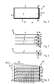
- FIGS. 1 to 8 Ammunition containers 1, 101, 201 according to the invention are shown.
- the ammunition containers 1, 101, 201 each have a rectangular bottom 24 and side walls 4, 5 on the longitudinal sides 25 and end faces 16.
- the end faces 16 are narrower than the longitudinal sides 25.
- a lid is pivotally mounted on the upper end of a side wall 4, 5 and securable with a closure against unintentional opening of the ammunition container 1, 101, 201.
- the cover is not shown in the figures for the sake of schematic simplicity.
- a ammunition belt 2 with ammunition 3 can be inserted in the ammunition container 1, 101, 201 .
- the ammunition belt 2 consists of a plurality of hingedly interconnected elements 26, in the ammunition 3 in the form of cartridges 27 can be inserted.
- the ammunition belt 2 is in several layers 7-15 in the ammunition container 1, 101, 201 layerable. A maximum of ten layers 7-15 can be arranged in the ammunition containers 1, 101, 201 shown.
- the guide elements 6 are in particular designed as guide plates which extend over almost the entire length L of the layer 7-15 and the width B of the ammunition container 1, 101, 201.
- the guide elements 6 are pivotally mounted via hinges 17 on a side wall 4 on an end face 16.
- the guide plates 6 are therefore opposite a horizontal axis HA, the hinge axis, pivotable upwards.
- Several guide elements 6 are provided spaced from each other.
- the hinges 17 may be formed such that one leg 28 of the hinge 17 on the guide member 6 and another leg 29 are attached directly to a side wall 4. When removing the ammunition belt 2, the guide elements 6 come successively to each other to the plant, after the ammunition belt 2 is partially pulled out, as in Fig. 3 shown.
- the guide elements 6 are provided in one-sided arrangement between each second layer 8-15 of the ammunition belt 2.
- the ammunition 3 is pulled out of the ammunition containers 1, 101, 201 by a feed system 30 and fed to a weapon system 31, shown schematically.
- the feeding system 30 is shown simplified by rollers 32.
- the ammunition 3 is usually pulled out of the ammunition container 1, 201 in a lateral direction. In the case of a lateral extension direction AR, it makes sense to support the guide elements 6 in a side wall 4 opposite to the extension direction AR.
- the guide elements 6 may be provided with an angled portion 22 or with a wedge 23 to the cartridges 27 on the entire contour 21 also in the region of the tapered tip 33 support. Furthermore, it is shown that the guide elements 6 extend in width B over almost the entire clear width LB of the ammunition container 1.
- the guide elements 6 can be arranged on opposite side walls 4 of the ammunition container 101 alternately and offset in height.
- the guide elements 6 are provided between each layer 7-15 of the ammunition belt 2.
- the reciprocal and offset arrangement is particularly advantageous when the feed system 30 is arranged centrally and above the ammunition container 101 and the extension direction AR is directed vertically upwards.
- the guide elements 6 overlap across the width BP of a cartridge 27 when they are arranged in horizontal alignment HAR between the layers 8-15 of the ammunition 3.
- FIGS. 5 to 8 a preferred embodiment of the ammunition container 201 is shown, in which either as a single module 34 (FIG. Fig. 6 ) a guide element 6 via a hinge 17 on a base body 18 or as a complete module 35 (FIG. Fig. 7 ) a plurality of guide elements 6 spaced from each other are fixed to a base body 19.
- the main body 18, 19 are rectangular plates 36, in particular made of sheet metal.
- One or more base bodies 18, 19 can be inserted into a guide rail 20 in the ammunition container 201.
- the guide rail 20 is formed by two opposite from a side wall 4 at an end face 16 spaced webs 37. At the upper end 38 of the guide rail 20, the base plates 18, 19 secured against unintentional withdrawal from the guide rail 20 by a biased by a spring 38 locking element 39.
Landscapes
- Engineering & Computer Science (AREA)
- General Engineering & Computer Science (AREA)
- Packaging Of Annular Or Rod-Shaped Articles, Wearing Apparel, Cassettes, Or The Like (AREA)
- Warehouses Or Storage Devices (AREA)
- Automotive Seat Belt Assembly (AREA)
Abstract
Description
- Die Erfindung betrifft einen Munitionsbehälter zur Aufnahme eines Munitionsgurts mit Munition.
- Derartige Munitionsbehälter sind im Stand der Technik bekannt. Sie werden insbesondere im Zusammenhang mit Waffensystemen verwendet, bei denen es darauf ankommt, einen mit Patronen bestückten Munitionsgurt mit hoher Geschwindigkeit einem Waffensystem zuzuführen. Derartige Behälter haben in der Regel die Form eines Quaders mit einem Boden, einem Deckel und Seitenwänden. Die Breite des Bodens entspricht der Länge der aufzunehmenden Munition. Die aufmunitionierten Munitionsgurte werden in den Behälter schlangenförmig bzw. mäanderförmig eingelegt, so dass der Munitionsgurt in einzelne Lagen geschichtet angeordnet ist. Man spricht auch vom Einfalten des Munitionsgurts oder einer schlingenartigen Anordnung des Munitionsgurts.
- Als nachteilig an den bekannten Munitionsbehältern hat sich herausgestellt, dass sich die Lage der Munition im Munitionsbehälter bei Lagerung, insbesondere aber beim Transport bzw. bei Bewegung des Munitionsbehälters verändert, so dass sich die Munition verkeilt und daher nur mit erhöhtem Kraftaufwand aus dem Munitionsbehälter herausgezogen werden kann. Das Problem der Lageänderungen tritt insbesondere dann auf, wenn der Munitionsbehälter bereits teilweise entleert ist. In der Folge ergeben sich am nachgeschalteten Waffensystem Funktionsstörungen, weil die Munition nicht mehr einwandfrei und leichtgängig zugeführt wird.
- Die
DE 25 44 208 C2 zeigt einen Munitionsbehälter mit verschiebbaren, stabförmigen Elementen zur Stabilisierung, die in gegenüberliegenden Führungsschlitzen translatorisch geführt werden. Durch die Führung kann jedoch ein Verkanten der Stäbe auftreten, wodurch die Funktionsfähigkeit behindert sein kann. - Der Erfindung liegt ausgehend vom Stand der Technik die Aufgabe zugrunde, einen Munitionsbehälter aufzuzeigen, bei welchem mit hoher Funktionsfähigkeit die Munition in der Lage stabilisiert ist.
- Die Lösung dieser Aufgabe besteht in einem Munitionsbehälter mit den Merkmalen des Anspruchs 1. Vorteilhafte Weiterentwicklungen des Munitionsbehälters gehen aus den Unteransprüchen 2 bis 14 hervor.
- Beim erfindungsgemäßen Munitionsbehälter zur Aufnahme eines Munitionsgurts mit Munition ist an einer Seitenwand wenigstens ein Führungselement zur Kippstabilisierung der Munition schwenkbar gelagert.
- Der besondere Vorteil der erfindungsgemäßen Lösung ist darin zu sehen, dass das Führungselement die Munition in der Lage, insbesondere hinsichtlich Kippen, stabilisiert. Die Kontur der Munition kann an einem Ende konisch verjüngt sein. Dadurch ergibt sich eine Neigung der Munition an diesem Ende einzusacken, d.h. zu kippen. Durch das Kippen kommt es zur Verkeilung oder Verkantung der Munition im Munitionsbehälter. Aufgrund des im Behälter angeordneten Führungselements wird das Kippen unterbunden, so dass die Munition auch bei längerer Lagerung und hohen Beschleunigungen stets bezüglich ihrer Längsachse parallel ausgerichtet bleibt. Auf diese Weise ist eine einwandfreie und leichtgängige Zuführung der Munition über ein Zuführsystem zu einem Waffensystem gewährleistet. Die Länge des Führungselements entspricht mindestens der Hälfte der Länge des Munitionsbehälters. Das Führungselement kann sich in der Breite über die lichte Breite des Munitionsbehälters erstrecken. Beim Ausziehen der Munition wird das Führungselement mitgenommen und in Auszugsrichtung, insbesondere nach oben, verschwenkt.
- Die Erfindung umfasst auch ein Waffensystem mit einem Zuführsystem, dem ein erfindungsgemäßer Munitionsbehälter zugeordnet ist, sowie ein Zuführsystem, an das ein erfindungsgemäßer Munitionsbehälter gekoppelt ist. Gegenstand der Erfindung ist weiterhin ein erfindungsgemäßer Munitionsbehälter mit Munition.
- Besonders vorteilhaft ist das Führungselement derart gelagert, dass das Führungselement zwischen zwei Lagen des Munitionsgurts einlegbar ist, insbesondere zwischen jede zweite oder vierte Lage. Auf diese Weise kann das Führungselement die Munition direkt abstützen und gegen Kippen sichern. Das Führungselement kann sich über einen Großteil der Länge einer Lage erstrecken. Es kann sich aber auch nur bis etwa zur Mitte des Munitionsbehälters erstrecken. Letzteres ist besonders dann vorteilhaft, wenn die Auszugsrichtung der Munition nicht seitlich, sondern in der Mitte vertikal nach oben gerichtet ist.
- Zweckmäßigerweise ist das Führungselement an einer Stirnseite des Munitionsbehälters gelagert. Die stirnseitige Lagerung ermöglicht es, das Führungselement besonders einfach zwischen den Lagen zu platzieren. Dies ist besonders raumsparend. Durch die derart angeordneten Führungselemente wird die Kapazität des Munitionsbehälters für die Aufnahme von Munition nicht verringert. Die Munition muss auch nicht mehr, wie bei älteren Munitionsbehältern entlang von schlangenförmigen Führungsschienen gezogen werden. Auf diese Weise kann die Munition mit erheblich geringerem Kraftaufwand aus dem Munitionsbehälter gezogen werden.
- Das Führungselement kann an einer einer Auszugsrichtung der Munition entgegengesetzten Seitenwand des Munitionsbehälters gelagert sein. Bei dieser Anordnung ist der Winkel, um den die Führungselemente beim Herausziehen der Munition verschwenkt werden müssen, besonders gering. Weiterhin stellen die Führungselemente keine Hindernisse dar, um die die Munition herumgezogen werden müsste. Somit ist diese Anordnung besonders effizient.
- Das Führungselement ist insbesondere um eine horizontale Achse schwenkbar. Die Schwenkachse ist vorzugsweise in der Nähe der Seitenwand, an der das Führungselement befestigt ist, vorgesehen. Bei dieser Anordnung ist es besonders einfach, den Munitionsgurt mit Munition in den Munitionsbehälter einzulegen.
- Das Führungselement kann plattenförmig sein. Vorzugsweise ist das Führungselement ein Führungsblech. Da der Munitionsbehälter in der Regel ebenfalls aus Blech hergestellt ist, ergeben sich durch die Verwendung des gleichen Materials Vorteile bei der Herstellung, insbesondere Vereinfachungen bei der Materialbeschaffung und bei der Verarbeitung. Zudem ist ein vollständig aus Blech hergestellter Munitionsbehälter besonders langlebig.
- Mehrere Führungselemente können an einer Seitenwand beabstandet voneinander gelagert sein. Mithin können mehrere Lagen der Munition in einem Munitionsbehälter lagestabilisiert werden. Diese Anordnung ist insbesondere bei Munitionsbehältern mit großer Kapazität von Vorteil, in denen die Munition in einer Vielzahl von Schichten gelagert wird.
- Mehrere Führungselemente können an gegenüberliegenden Seitenwänden des Munitionsbehälters wechselseitig und höhenversetzt gelagert sein. Diese Anordnung der Führungselemente ist besonders vorteilhaft, wenn die Auszugsrichtung mittig und vertikal nach oben ist. Auch in diesem Fall sind die Schwenkwinkel der Führungselemente beim Herausziehen der Munition gering, so dass der Munitionsgurt mit geringem Kraftaufwand gezogen werden kann.
- Vorteilhaft können sich die wechselseitigen Führungselemente bei horizontaler Ausrichtung überlappen. Die Überlappung stellt sicher, dass eine Doppellage der Munition über die gesamte Länge von Führungselementen gestützt wird.
- Das Führungselement kann über ein Gelenk, insbesondere ein Scharnier, an der Seitenwand gelagert sein. Derartige Gelenke sind besonders widerstandsfähig und wartungsarm. Sie stellen dennoch die geforderte Schwenkbarkeit des Führungselements dauerhaft sicher.
- In einer besonders vorteilhaften Ausführungsform ist mindestens ein Führungselement über ein Gelenk an einem Grundkörper, insbesondere einer Grundplatte, gelagert und der Grundkörper ist in eine Führungsschiene im Munitionsbehälter einschiebbar. Diese Ausführungsform ermöglicht eine besonders flexible Ausrüstung von Munitionsbehältern mit Führungselementen. Die Führungselemente können je nach Bedarf auch herausgenommen oder ausgetauscht werden. Weiterhin ist eine Nachrüstung von Munitionsbehältern mit Führungselementen möglich.
- Vorteilhaft ist der in die Führungsschiene eingeschobene Grundkörper gegen Herausziehen aus der Führungsschiene sicherbar. Auf diese Weise wird verhindert, dass sich die Teile des Munitionsbehälters beim Einsatz voneinander lösen und durch das Lösen Folgeschäden auftreten.
- Zweckmäßigerweise ist ein Führungselement in Anpassung an die Kontur der Munition mit einer Abwinklung versehen. Alternativ kann an einem Führungselement in Anpassung an die Kontur der Munition ein Keil befestigt sein. Beide Lösungen ermöglichen es, die Munition über die gesamte Länge abzustützen.
- Die Erfindung ist nachfolgend anhand von mehreren in den Figuren dargestellten Ausführungsbeispielen näher erläutert. Es zeigen:
- Fig. 1
- ein Waffensystem mit einem Zuführsystem, an das ein erfindungsgemäßer Munitionsbehälter angekoppelt ist;
- Fig. 2
- eine Seitenansicht des Munitionsbehälters von
Fig. 1 ; - Fig. 3
- der Munitionsbehälter der
Fig. 1 nach teilweiser Entleerung; - Fig. 4
- eine Ausführungsform des Munitionsbehälters mit wechselseitig angeordneten Führungselementen;
- Fig. 5
- eine Draufsicht auf einen Munitionsbehälter mit einer Führungsschiene;
- Fig. 6
- ein Einzelmodul mit einem Führungselement;
- Fig. 7
- ein Komplettmodul mit mehreren Führungselementen; und
- Fig. 8
- eine Seitenansicht eines Munitionsbehälters mit mehreren Einzelmodulen.
- Gleiche Merkmale in den Figuren sind mit identischen Bezugszeichen versehen.
- In den
Figuren 1 bis 8 sind erfindungsgemäße Munitionsbehälter 1, 101, 201 gezeigt. Die Munitionsbehälter 1, 101, 201 weisen jeweils einen rechteckigen Boden 24 und Seitenwände 4, 5 an den Längsseiten 25 und Stirnseiten 16 auf. Die Stirnseiten 16 sind schmaler als die Längsseiten 25. In der Regel ist ein Deckel schwenkbar am oberen Ende einer Seitenwand 4, 5 gelagert und mit einem Verschluss gegen unbeabsichtigtes Öffnen des Munitionsbehälters 1, 101, 201 sicherbar. Der Deckel ist aber aus Gründen der schematischen Vereinfachung in den Figuren nicht dargestellt. - In den Munitionsbehälter 1, 101, 201 ist ein Munitionsgurt 2 mit Munition 3 einlegbar. Der Munitionsgurt 2 besteht aus einer Vielzahl von gelenkig miteinander verbundenen Elementen 26, in die Munition 3 in Form von Patronen 27 einschiebbar ist. Der Munitionsgurt 2 ist in mehreren Lagen 7-15 im Munitionsbehälter 1, 101, 201 schichtbar. Maximal können in den gezeigten Munitionsbehältern 1, 101, 201 zehn Lagen 7-15 angeordnet werden.
- Zwischen den Lagen 8-15 sind Führungselemente 6 zur Kippstabilisierung angeordnet. Die Führungselemente 6 sind insbesondere als Führungsbleche ausgebildet, die sich über fast die gesamte Länge L der Lage 7-15 und die Breite B des Munitionsbehälters 1, 101, 201 erstrecken. Endseitig sind die Führungselemente 6 über Gelenke 17 an einer Seitenwand 4 an einer Stirnseite 16 schwenkbar gelagert. Die Führungsbleche 6 sind mithin gegenüber einer horizontalen Achse HA, der Gelenkachse, nach oben verschwenkbar. Mehrere Führungselemente 6 sind beabstandet voneinander vorgesehen. Die Scharniere 17 können derart ausgebildet sein, dass ein Schenkel 28 des Scharniers 17 am Führungselement 6 und ein weiterer Schenkel 29 direkt an einer Seitenwand 4 befestigt sind. Beim Ausziehen des Munitionsgurts 2 kommen die Führungselemente 6 nacheinander aneinander zur Anlage, nachdem der Munitionsgurt 2 teilweise ausgezogen ist, wie in
Fig. 3 gezeigt. Die Führungselemente 6 sind bei einseitiger Anordnung zwischen jeder zweiten Lage 8-15 des Munitionsgurts 2 vorgesehen. - Die Munition 3 wird aus den Munitionsbehältern 1, 101, 201 von einem Zuführsystem 30 herausgezogen und einem schematisch dargestellten Waffensystem 31 zugeführt. Das Zuführsystem 30 ist vereinfacht durch Rollen 32 dargestellt. Die Munition 3 wird dabei in der Regel in einer seitlichen Richtung aus dem Munitionsbehälter 1, 201 herausgezogen. Bei seitlicher Auszugsrichtung AR bietet es sich an, die Führungselemente 6 an einer der Auszugsrichtung AR entgegengesetzten Seitenwand 4 zu lagern.
- In
Fig. 2 ist gezeigt, dass die Führungselemente 6 mit einer Abwinklung 22 oder mit einem Keil 23 versehen sein können, um die Patronen 27 über die gesamte Kontur 21 auch im Bereich der verjüngten Spitze 33 abzustützen. Weiterhin ist dargestellt, dass sich die Führungselemente 6 in der Breite B über fast die gesamte lichte Breite LB des Munitionsbehälters 1 erstrecken. - Wie man in
Fig. 4 sehen kann, können die Führungselemente 6 auch an gegenüberliegenden Seitenwänden 4 des Munitionsbehälters 101 wechselseitig und höhenversetzt angeordnet sein. Bei dieser Ausführungsform sind die Führungselemente 6 zwischen jeder Lage 7-15 des Munitionsgurts 2 vorgesehen. Die wechselseitige und höhenversetzte Anordnung ist insbesondere dann vorteilhaft, wenn das Zuführsystem 30 mittig und oberhalb des Munitionsbehälters 101 angeordnet und die Auszugsrichtung AR vertikal nach oben gerichtet ist. Bei dieser Ausführungsform überlappen sich die Führungselemente 6 über die Breite BP einer Patrone 27, wenn sie in horizontaler Ausrichtung HAR zwischen den Lagen 8-15 der Munition 3 angeordnet sind. - In den
Figuren 5 bis 8 ist eine bevorzugte Ausführungsform des Munitionsbehälters 201 gezeigt, bei dem entweder als Einzelmodul 34 (Fig. 6 ) ein Führungselement 6 über ein Scharnier 17 an einem Grundkörper 18 oder als Komplettmodul 35 (Fig. 7 ) mehrere Führungselemente 6 beabstandet voneinander an einer Grundkörper 19 befestigt sind. Die Grundkörper 18, 19 sind rechteckige Platten 36, insbesondere aus Blech. Eine oder mehrere Grundkörper 18, 19 sind in eine Führungsschiene 20 im Munitionsbehälter 201 einschiebbar. Die Führungsschiene 20 ist durch zwei gegenüberliegende von einer Seitenwand 4 an einer Stirnseite 16 beabstandete Stege 37 gebildet. Am oberen Ende 38 der Führungsschiene 20 sind die Grundplatten 18, 19 gegen unbeabsichtigtes Herausziehen aus der Führungsschiene 20 durch ein von einer Feder 38 beaufschlagtes Sperrelement 39 gesichert. -
- 1
- Munitionsbehälter
- 2
- Munitionsgurt
- 3
- Munition
- 4
- Seitenwand
- 5
- Seitenwand
- 6
- Führungselement
- 7
- Lage
- 8
- Lage
- 9
- Lage
- 10
- Lage
- 11
- Lage
- 12
- Lage
- 13
- Lage
- 14
- Lage
- 15
- Lage
- 16
- Stirnseite
- 17
- Gelenk, insbesondere Scharnier
- 18
- Grundkörper
- 19
- Grundkörper
- 20
- Führungsschiene
- 21
- Kontur
- 22
- Abwinklung
- 23
- Keil
- 24
- Boden
- 25
- Längsseite
- 26
- Element
- 27
- Patrone
- 28
- Schenkel
- 29
- Schenkel
- 30
- Zuführsystem
- 31
- Waffensystem
- 32
- Rolle
- 33
- Spitze
- 34
- Einzelmodul
- 35
- Komplettmodul
- 36
- Platte
- 37
- Steg
- 38
- Feder
- 39
- Sperrelement
- 101
- Munitionsbehälter
- 201
- Munitionsbehälter
- HA
- horizontale Achse von 17
- HAR
- horizontale Ausrichtung von 6
- AR
- Auszugsrichtung von 2
- B
- Breite von 1, 101, 201
- L
- Länge von 1, 101, 201
- LB
- lichte Breite von 1, 101, 201
- PB
- Breite von 27
Claims (14)
- Munitionsbehälter zur Aufnahme eines Munitionsgurts (2) mit Munition (3), dadurch gekennzeichnet, dass an einer Seitenwand (4, 5) wenigstens ein Führungselement (6) zur Kippstabilisierung der Munition (3) schwenkbar gelagert ist.
- Munitionsbehälter nach Anspruch 1, dadurch gekennzeichnet, dass das Führungselement (6) derart gelagert ist, dass das Führungselement (6) zwischen zwei Lagen (7-15) des Munitionsgurts (2) einlegbar ist, insbesondere zwischen jede zweite oder vierte Lage (8-15).
- Munitionsbehälter nach einem der vorhergehenden Ansprüche, dadurch gekennzeichnet, dass das Führungselement (6) an einer Stirnseite (16) des Munitionsbehälters gelagert ist.
- Munitionsbehälter nach einem der vorhergehenden Ansprüche, dadurch gekennzeichnet, dass das Führungselement (6) an einer einer Auszugsrichtung (AR) der Munition (3) entgegengesetzten Seitenwand (4) des Munitionsbehälters gelagert ist.
- Munitionsbehälter nach einem der vorhergehenden Ansprüche, dadurch gekennzeichnet, dass das Führungselement (6) um eine horizontale Achse (HA) schwenkbar ist.
- Munitionsbehälter nach einem der vorhergehenden Ansprüche, dadurch gekennzeichnet, dass das Führungselement (6) plattenförmig ist.
- Munitionsbehälter nach einem der vorhergehenden Ansprüche, dadurch gekennzeichnet, dass mehrere Führungselemente (6) an einer Seitenwand (4, 5) beabstandet voneinander gelagert sind.
- Munitionsbehälter nach einem der vorhergehenden Ansprüche, dadurch gekennzeichnet, dass mehrere Führungselemente (6) an gegenüberliegenden Seitenwänden (4, 5) des Munitionsbehälters wechselseitig und höhenversetzt gelagert sind.
- Munitionsbehälter nach Anspruch 8, dadurch gekennzeichnet, dass sich die wechselseitigen Führungselemente (6) bei horizontaler Ausrichtung (HAR) überlappen.
- Munitionsbehälter nach einem der vorhergehenden Ansprüche, dadurch gekennzeichnet, dass das Führungselement (6) über ein Gelenk (17), insbesondere ein Scharnier, an der Seitenwand (4, 5) gelagert ist.
- Munitionsbehälter nach einem der vorhergehenden Ansprüche, dadurch gekennzeichnet, dass mindestens ein Führungselement (6) über ein Gelenk (17) an einem Grundkörper (18, 19) gelagert ist und der Grundkörper (18, 19) in eine Führungsschiene (20) im Munitionsbehälter einschiebbar ist.
- Munitionsbehälter nach Anspruch 11, dadurch gekennzeichnet, dass der in die Führungsschiene (20) eingeschobene Grundkörper (18, 19) gegen Herausziehen aus der Führungsschiene (20) sicherbar ist.
- Munitionsbehälter nach einem der vorhergehenden Ansprüche, dadurch gekennzeichnet, dass ein Führungselement (6) in Anpassung an die Kontur (21) der Munition (3) mit einer Abwinklung (22) versehen ist.
- Munitionsbehälter nach einem der vorhergehenden Ansprüche, dadurch gekennzeichnet, dass an einem Führungselement (6) in Anpassung an die Kontur (21) der Munition (3) ein Keil (23) befestigt ist.
Applications Claiming Priority (1)
| Application Number | Priority Date | Filing Date | Title |
|---|---|---|---|
| DE201110054325 DE102011054325B9 (de) | 2011-10-10 | 2011-10-10 | Munitionsbehälter |
Publications (3)
| Publication Number | Publication Date |
|---|---|
| EP2581697A2 true EP2581697A2 (de) | 2013-04-17 |
| EP2581697A3 EP2581697A3 (de) | 2014-12-17 |
| EP2581697B1 EP2581697B1 (de) | 2016-02-24 |
Family
ID=46970157
Family Applications (1)
| Application Number | Title | Priority Date | Filing Date |
|---|---|---|---|
| EP12187561.1A Not-in-force EP2581697B1 (de) | 2011-10-10 | 2012-10-08 | Munitionsbehälter |
Country Status (2)
| Country | Link |
|---|---|
| EP (1) | EP2581697B1 (de) |
| DE (1) | DE102011054325B9 (de) |
Cited By (1)
| Publication number | Priority date | Publication date | Assignee | Title |
|---|---|---|---|---|
| CN108332621A (zh) * | 2018-04-03 | 2018-07-27 | 西安昆仑工业(集团)有限责任公司 | 一种链式武器用弹箱 |
Citations (1)
| Publication number | Priority date | Publication date | Assignee | Title |
|---|---|---|---|---|
| DE2544208C2 (de) | 1975-10-03 | 1983-11-17 | Wegmann & Co, 3500 Kassel | Munitionsbehälter für gegurtete Munition für automatische Waffen |
Family Cites Families (10)
| Publication number | Priority date | Publication date | Assignee | Title |
|---|---|---|---|---|
| GB759060A (en) * | 1954-01-18 | 1956-10-10 | Brevets Aero Mecaniques | Improvements in ammunition magazines for guns |
| US2874615A (en) * | 1955-03-28 | 1959-02-24 | Nobles Engineering Company | Ammunition storage box |
| FR1178742A (fr) * | 1957-07-11 | 1959-05-14 | Perfectionnement aux chargeurs de cartouches | |
| DE1800330C3 (de) * | 1968-10-01 | 1982-01-14 | Contraves AG, 8052 Zürich | Panzerfahrzeug mit Fliegerabwehrbewaffnung |
| DE2760173C2 (de) * | 1977-04-16 | 1986-08-07 | Rheinmetall GmbH, 4000 Düsseldorf | Munitionsmagazin mit Patronenförderer für eine automatische Rohrwaffe |
| US4213376A (en) * | 1978-07-26 | 1980-07-22 | Cadillac Gage Company | Storage and feeding apparatus for ammunition belts |
| US4393746A (en) * | 1981-07-31 | 1983-07-19 | The United States Of America As Represented By The Secretay Of The Army | Ammunition magazine with built-in compartment covers |
| EP0141109B1 (de) * | 1983-11-04 | 1988-01-20 | Werkzeugmaschinenfabrik Oerlikon-Bührle AG | Munitionsbehälter für gegurtete Munition |
| US4972758A (en) * | 1989-12-01 | 1990-11-27 | General Electric Company | Multiply adaptable magazine assembly |
| US6439098B1 (en) * | 2000-11-20 | 2002-08-27 | Michael J. Dillon | Ammunition box |
-
2011
- 2011-10-10 DE DE201110054325 patent/DE102011054325B9/de not_active Expired - Fee Related
-
2012
- 2012-10-08 EP EP12187561.1A patent/EP2581697B1/de not_active Not-in-force
Patent Citations (1)
| Publication number | Priority date | Publication date | Assignee | Title |
|---|---|---|---|---|
| DE2544208C2 (de) | 1975-10-03 | 1983-11-17 | Wegmann & Co, 3500 Kassel | Munitionsbehälter für gegurtete Munition für automatische Waffen |
Cited By (1)
| Publication number | Priority date | Publication date | Assignee | Title |
|---|---|---|---|---|
| CN108332621A (zh) * | 2018-04-03 | 2018-07-27 | 西安昆仑工业(集团)有限责任公司 | 一种链式武器用弹箱 |
Also Published As
| Publication number | Publication date |
|---|---|
| EP2581697B1 (de) | 2016-02-24 |
| DE102011054325B9 (de) | 2013-01-24 |
| EP2581697A3 (de) | 2014-12-17 |
| DE102011054325B3 (de) | 2013-01-17 |
Similar Documents
| Publication | Publication Date | Title |
|---|---|---|
| EP2792620B1 (de) | Transporttasche zum hängenden Transport von Waren sowie Beladestation und Förderanlage für diese Transporttaschen | |
| EP2786940B1 (de) | Beladestation für Transporttaschen zum hängenden Transport von Waren | |
| DE20101374U1 (de) | Vorrichtung für die Aufbewahrung und den Transport länglicher Gegenstände | |
| AT16353U1 (de) | Transporttasche sowie Verfahren zum Befüllen und Entleeren einer solchen Transporttasche | |
| DE202006002326U1 (de) | Kistenstapellager und Halteklinke für ein Kistenstapellager | |
| DE102016107248A1 (de) | Behälter zum Aufnehmen oder Abgeben von Portionen eines aus stabförmigen Artikeln der Tabak verarbeitenden Industrie gebildeten Produktmassenstroms, sowie Anordnung zum Diskretisieren oder Bilden eines Produktmassenstroms mit solchen Behältern | |
| DE69218605T2 (de) | Lager-und transportgestell für plattenteile | |
| EP2604493A2 (de) | Runge für einen Nutzfahrzeugaufbau | |
| EP2581697B1 (de) | Munitionsbehälter | |
| EP3491970B1 (de) | Regalbox | |
| DE69821438T2 (de) | Vorrichtung zum transport und zur lagerung von langgestreckten elementen wie stossfänger | |
| DE202016002839U1 (de) | Verpackungspapierdispenservorrichtung | |
| DE102006004823A1 (de) | Verriegelungseinrichtung für Containertüren | |
| DE102009000809A1 (de) | Vorhang-Auftragswerk | |
| DE102004060400A1 (de) | Transport- und Vorratsbehälter | |
| DE2318590C2 (de) | Konsole, die an einer Wand, insbesondere Schiffswand anbringbar ist, zur Aufnahme von Laufbrettern | |
| EP0471325A1 (de) | Befestigungsvorrichtung | |
| DE102019200050A1 (de) | Luftleitvorrichtung | |
| DE102005055890B4 (de) | Vorrichtung mit Führungsflächen zur Ablage von Bögen für eine Druckmaschine | |
| DE2943274A1 (de) | Vorrichtung zum verbinden von aufeinander gestapelten schaltafeln | |
| DE102006012557A1 (de) | Gitterfacheinsatz | |
| DE3725349C2 (de) | ||
| DE102012111267A1 (de) | Förderkanal einer Schwingfördereinrichtung | |
| DE202017104062U1 (de) | Abrollbehälter | |
| DE19510791C2 (de) | Vorrichtung zum Abgeben eines blattartigen Objekts aus einem Stapel |
Legal Events
| Date | Code | Title | Description |
|---|---|---|---|
| PUAI | Public reference made under article 153(3) epc to a published international application that has entered the european phase |
Free format text: ORIGINAL CODE: 0009012 |
|
| AK | Designated contracting states |
Kind code of ref document: A2 Designated state(s): AL AT BE BG CH CY CZ DE DK EE ES FI FR GB GR HR HU IE IS IT LI LT LU LV MC MK MT NL NO PL PT RO RS SE SI SK SM TR |
|
| AX | Request for extension of the european patent |
Extension state: BA ME |
|
| PUAL | Search report despatched |
Free format text: ORIGINAL CODE: 0009013 |
|
| AK | Designated contracting states |
Kind code of ref document: A3 Designated state(s): AL AT BE BG CH CY CZ DE DK EE ES FI FR GB GR HR HU IE IS IT LI LT LU LV MC MK MT NL NO PL PT RO RS SE SI SK SM TR |
|
| AX | Request for extension of the european patent |
Extension state: BA ME |
|
| RIC1 | Information provided on ipc code assigned before grant |
Ipc: F41A 9/34 20060101ALI20141107BHEP Ipc: F41A 9/79 20060101AFI20141107BHEP |
|
| 17P | Request for examination filed |
Effective date: 20150527 |
|
| RBV | Designated contracting states (corrected) |
Designated state(s): AL AT BE BG CH CY CZ DE DK EE ES FI FR GB GR HR HU IE IS IT LI LT LU LV MC MK MT NL NO PL PT RO RS SE SI SK SM TR |
|
| GRAP | Despatch of communication of intention to grant a patent |
Free format text: ORIGINAL CODE: EPIDOSNIGR1 |
|
| INTG | Intention to grant announced |
Effective date: 20150825 |
|
| GRAS | Grant fee paid |
Free format text: ORIGINAL CODE: EPIDOSNIGR3 |
|
| GRAA | (expected) grant |
Free format text: ORIGINAL CODE: 0009210 |
|
| AK | Designated contracting states |
Kind code of ref document: B1 Designated state(s): AL AT BE BG CH CY CZ DE DK EE ES FI FR GB GR HR HU IE IS IT LI LT LU LV MC MK MT NL NO PL PT RO RS SE SI SK SM TR |
|
| REG | Reference to a national code |
Ref country code: GB Ref legal event code: FG4D Free format text: NOT ENGLISH |
|
| REG | Reference to a national code |
Ref country code: CH Ref legal event code: EP |
|
| REG | Reference to a national code |
Ref country code: AT Ref legal event code: REF Ref document number: 776945 Country of ref document: AT Kind code of ref document: T Effective date: 20160315 |
|
| REG | Reference to a national code |
Ref country code: IE Ref legal event code: FG4D Free format text: LANGUAGE OF EP DOCUMENT: GERMAN |
|
| REG | Reference to a national code |
Ref country code: DE Ref legal event code: R096 Ref document number: 502012006036 Country of ref document: DE |
|
| REG | Reference to a national code |
Ref country code: NL Ref legal event code: FP |
|
| REG | Reference to a national code |
Ref country code: LT Ref legal event code: MG4D |
|
| PG25 | Lapsed in a contracting state [announced via postgrant information from national office to epo] |
Ref country code: NO Free format text: LAPSE BECAUSE OF FAILURE TO SUBMIT A TRANSLATION OF THE DESCRIPTION OR TO PAY THE FEE WITHIN THE PRESCRIBED TIME-LIMIT Effective date: 20160524 Ref country code: ES Free format text: LAPSE BECAUSE OF FAILURE TO SUBMIT A TRANSLATION OF THE DESCRIPTION OR TO PAY THE FEE WITHIN THE PRESCRIBED TIME-LIMIT Effective date: 20160224 Ref country code: GR Free format text: LAPSE BECAUSE OF FAILURE TO SUBMIT A TRANSLATION OF THE DESCRIPTION OR TO PAY THE FEE WITHIN THE PRESCRIBED TIME-LIMIT Effective date: 20160525 Ref country code: HR Free format text: LAPSE BECAUSE OF FAILURE TO SUBMIT A TRANSLATION OF THE DESCRIPTION OR TO PAY THE FEE WITHIN THE PRESCRIBED TIME-LIMIT Effective date: 20160224 Ref country code: FI Free format text: LAPSE BECAUSE OF FAILURE TO SUBMIT A TRANSLATION OF THE DESCRIPTION OR TO PAY THE FEE WITHIN THE PRESCRIBED TIME-LIMIT Effective date: 20160224 |
|
| PG25 | Lapsed in a contracting state [announced via postgrant information from national office to epo] |
Ref country code: SE Free format text: LAPSE BECAUSE OF FAILURE TO SUBMIT A TRANSLATION OF THE DESCRIPTION OR TO PAY THE FEE WITHIN THE PRESCRIBED TIME-LIMIT Effective date: 20160224 Ref country code: LV Free format text: LAPSE BECAUSE OF FAILURE TO SUBMIT A TRANSLATION OF THE DESCRIPTION OR TO PAY THE FEE WITHIN THE PRESCRIBED TIME-LIMIT Effective date: 20160224 Ref country code: PL Free format text: LAPSE BECAUSE OF FAILURE TO SUBMIT A TRANSLATION OF THE DESCRIPTION OR TO PAY THE FEE WITHIN THE PRESCRIBED TIME-LIMIT Effective date: 20160224 Ref country code: RS Free format text: LAPSE BECAUSE OF FAILURE TO SUBMIT A TRANSLATION OF THE DESCRIPTION OR TO PAY THE FEE WITHIN THE PRESCRIBED TIME-LIMIT Effective date: 20160224 Ref country code: PT Free format text: LAPSE BECAUSE OF FAILURE TO SUBMIT A TRANSLATION OF THE DESCRIPTION OR TO PAY THE FEE WITHIN THE PRESCRIBED TIME-LIMIT Effective date: 20160624 Ref country code: LT Free format text: LAPSE BECAUSE OF FAILURE TO SUBMIT A TRANSLATION OF THE DESCRIPTION OR TO PAY THE FEE WITHIN THE PRESCRIBED TIME-LIMIT Effective date: 20160224 |
|
| REG | Reference to a national code |
Ref country code: FR Ref legal event code: PLFP Year of fee payment: 5 |
|
| PG25 | Lapsed in a contracting state [announced via postgrant information from national office to epo] |
Ref country code: EE Free format text: LAPSE BECAUSE OF FAILURE TO SUBMIT A TRANSLATION OF THE DESCRIPTION OR TO PAY THE FEE WITHIN THE PRESCRIBED TIME-LIMIT Effective date: 20160224 Ref country code: DK Free format text: LAPSE BECAUSE OF FAILURE TO SUBMIT A TRANSLATION OF THE DESCRIPTION OR TO PAY THE FEE WITHIN THE PRESCRIBED TIME-LIMIT Effective date: 20160224 |
|
| REG | Reference to a national code |
Ref country code: DE Ref legal event code: R097 Ref document number: 502012006036 Country of ref document: DE |
|
| PG25 | Lapsed in a contracting state [announced via postgrant information from national office to epo] |
Ref country code: SM Free format text: LAPSE BECAUSE OF FAILURE TO SUBMIT A TRANSLATION OF THE DESCRIPTION OR TO PAY THE FEE WITHIN THE PRESCRIBED TIME-LIMIT Effective date: 20160224 Ref country code: RO Free format text: LAPSE BECAUSE OF FAILURE TO SUBMIT A TRANSLATION OF THE DESCRIPTION OR TO PAY THE FEE WITHIN THE PRESCRIBED TIME-LIMIT Effective date: 20160224 Ref country code: SK Free format text: LAPSE BECAUSE OF FAILURE TO SUBMIT A TRANSLATION OF THE DESCRIPTION OR TO PAY THE FEE WITHIN THE PRESCRIBED TIME-LIMIT Effective date: 20160224 |
|
| PLBE | No opposition filed within time limit |
Free format text: ORIGINAL CODE: 0009261 |
|
| STAA | Information on the status of an ep patent application or granted ep patent |
Free format text: STATUS: NO OPPOSITION FILED WITHIN TIME LIMIT |
|
| 26N | No opposition filed |
Effective date: 20161125 |
|
| PG25 | Lapsed in a contracting state [announced via postgrant information from national office to epo] |
Ref country code: BG Free format text: LAPSE BECAUSE OF FAILURE TO SUBMIT A TRANSLATION OF THE DESCRIPTION OR TO PAY THE FEE WITHIN THE PRESCRIBED TIME-LIMIT Effective date: 20160524 Ref country code: SI Free format text: LAPSE BECAUSE OF FAILURE TO SUBMIT A TRANSLATION OF THE DESCRIPTION OR TO PAY THE FEE WITHIN THE PRESCRIBED TIME-LIMIT Effective date: 20160224 Ref country code: BE Free format text: LAPSE BECAUSE OF NON-PAYMENT OF DUE FEES Effective date: 20161031 |
|
| REG | Reference to a national code |
Ref country code: CH Ref legal event code: PL |
|
| GBPC | Gb: european patent ceased through non-payment of renewal fee |
Effective date: 20161008 |
|
| REG | Reference to a national code |
Ref country code: IE Ref legal event code: MM4A |
|
| PG25 | Lapsed in a contracting state [announced via postgrant information from national office to epo] |
Ref country code: LI Free format text: LAPSE BECAUSE OF NON-PAYMENT OF DUE FEES Effective date: 20161031 Ref country code: GB Free format text: LAPSE BECAUSE OF NON-PAYMENT OF DUE FEES Effective date: 20161008 Ref country code: CH Free format text: LAPSE BECAUSE OF NON-PAYMENT OF DUE FEES Effective date: 20161031 |
|
| PG25 | Lapsed in a contracting state [announced via postgrant information from national office to epo] |
Ref country code: LU Free format text: LAPSE BECAUSE OF NON-PAYMENT OF DUE FEES Effective date: 20161008 |
|
| REG | Reference to a national code |
Ref country code: FR Ref legal event code: PLFP Year of fee payment: 6 |
|
| PG25 | Lapsed in a contracting state [announced via postgrant information from national office to epo] |
Ref country code: IE Free format text: LAPSE BECAUSE OF NON-PAYMENT OF DUE FEES Effective date: 20161008 |
|
| REG | Reference to a national code |
Ref country code: BE Ref legal event code: MM Effective date: 20161031 |
|
| PG25 | Lapsed in a contracting state [announced via postgrant information from national office to epo] |
Ref country code: CY Free format text: LAPSE BECAUSE OF FAILURE TO SUBMIT A TRANSLATION OF THE DESCRIPTION OR TO PAY THE FEE WITHIN THE PRESCRIBED TIME-LIMIT Effective date: 20160224 Ref country code: HU Free format text: LAPSE BECAUSE OF FAILURE TO SUBMIT A TRANSLATION OF THE DESCRIPTION OR TO PAY THE FEE WITHIN THE PRESCRIBED TIME-LIMIT; INVALID AB INITIO Effective date: 20121008 |
|
| PG25 | Lapsed in a contracting state [announced via postgrant information from national office to epo] |
Ref country code: MK Free format text: LAPSE BECAUSE OF FAILURE TO SUBMIT A TRANSLATION OF THE DESCRIPTION OR TO PAY THE FEE WITHIN THE PRESCRIBED TIME-LIMIT Effective date: 20160224 Ref country code: MC Free format text: LAPSE BECAUSE OF FAILURE TO SUBMIT A TRANSLATION OF THE DESCRIPTION OR TO PAY THE FEE WITHIN THE PRESCRIBED TIME-LIMIT Effective date: 20160224 Ref country code: IS Free format text: LAPSE BECAUSE OF FAILURE TO SUBMIT A TRANSLATION OF THE DESCRIPTION OR TO PAY THE FEE WITHIN THE PRESCRIBED TIME-LIMIT Effective date: 20160224 Ref country code: MT Free format text: LAPSE BECAUSE OF FAILURE TO SUBMIT A TRANSLATION OF THE DESCRIPTION OR TO PAY THE FEE WITHIN THE PRESCRIBED TIME-LIMIT Effective date: 20160224 |
|
| REG | Reference to a national code |
Ref country code: FR Ref legal event code: PLFP Year of fee payment: 7 |
|
| PG25 | Lapsed in a contracting state [announced via postgrant information from national office to epo] |
Ref country code: AL Free format text: LAPSE BECAUSE OF FAILURE TO SUBMIT A TRANSLATION OF THE DESCRIPTION OR TO PAY THE FEE WITHIN THE PRESCRIBED TIME-LIMIT Effective date: 20160224 |
|
| REG | Reference to a national code |
Ref country code: AT Ref legal event code: MM01 Ref document number: 776945 Country of ref document: AT Kind code of ref document: T Effective date: 20171008 |
|
| PG25 | Lapsed in a contracting state [announced via postgrant information from national office to epo] |
Ref country code: AT Free format text: LAPSE BECAUSE OF NON-PAYMENT OF DUE FEES Effective date: 20171008 |
|
| PGFP | Annual fee paid to national office [announced via postgrant information from national office to epo] |
Ref country code: NL Payment date: 20201020 Year of fee payment: 9 Ref country code: TR Payment date: 20201001 Year of fee payment: 9 |
|
| PGFP | Annual fee paid to national office [announced via postgrant information from national office to epo] |
Ref country code: CZ Payment date: 20201002 Year of fee payment: 9 Ref country code: IT Payment date: 20201030 Year of fee payment: 9 Ref country code: FR Payment date: 20201020 Year of fee payment: 9 Ref country code: DE Payment date: 20201031 Year of fee payment: 9 |
|
| REG | Reference to a national code |
Ref country code: DE Ref legal event code: R119 Ref document number: 502012006036 Country of ref document: DE |
|
| PG25 | Lapsed in a contracting state [announced via postgrant information from national office to epo] |
Ref country code: CZ Free format text: LAPSE BECAUSE OF NON-PAYMENT OF DUE FEES Effective date: 20211008 |
|
| REG | Reference to a national code |
Ref country code: NL Ref legal event code: MM Effective date: 20211101 |
|
| PG25 | Lapsed in a contracting state [announced via postgrant information from national office to epo] |
Ref country code: NL Free format text: LAPSE BECAUSE OF NON-PAYMENT OF DUE FEES Effective date: 20211101 Ref country code: DE Free format text: LAPSE BECAUSE OF NON-PAYMENT OF DUE FEES Effective date: 20220503 |
|
| PG25 | Lapsed in a contracting state [announced via postgrant information from national office to epo] |
Ref country code: FR Free format text: LAPSE BECAUSE OF NON-PAYMENT OF DUE FEES Effective date: 20211031 |
|
| PG25 | Lapsed in a contracting state [announced via postgrant information from national office to epo] |
Ref country code: IT Free format text: LAPSE BECAUSE OF NON-PAYMENT OF DUE FEES Effective date: 20211008 |
|
| PG25 | Lapsed in a contracting state [announced via postgrant information from national office to epo] |
Ref country code: TR Free format text: LAPSE BECAUSE OF NON-PAYMENT OF DUE FEES Effective date: 20211008 |