EP2573209B1 - Solarzellenintegrierte gasherstellungsvorrichtung - Google Patents
Solarzellenintegrierte gasherstellungsvorrichtung Download PDFInfo
- Publication number
- EP2573209B1 EP2573209B1 EP11783343.4A EP11783343A EP2573209B1 EP 2573209 B1 EP2573209 B1 EP 2573209B1 EP 11783343 A EP11783343 A EP 11783343A EP 2573209 B1 EP2573209 B1 EP 2573209B1
- Authority
- EP
- European Patent Office
- Prior art keywords
- photoelectric conversion
- electrolysis electrode
- changeover
- conversion part
- electrode
- Prior art date
- Legal status (The legal status is an assumption and is not a legal conclusion. Google has not performed a legal analysis and makes no representation as to the accuracy of the status listed.)
- Not-in-force
Links
- 238000004519 manufacturing process Methods 0.000 title claims description 106
- 238000005868 electrolysis reaction Methods 0.000 claims description 291
- 238000006243 chemical reaction Methods 0.000 claims description 281
- 239000007789 gas Substances 0.000 claims description 202
- 239000008151 electrolyte solution Substances 0.000 claims description 105
- 239000004065 semiconductor Substances 0.000 claims description 101
- 239000000463 material Substances 0.000 claims description 66
- UFHFLCQGNIYNRP-UHFFFAOYSA-N Hydrogen Chemical compound [H][H] UFHFLCQGNIYNRP-UHFFFAOYSA-N 0.000 claims description 61
- 230000001678 irradiating effect Effects 0.000 claims description 56
- 239000000758 substrate Substances 0.000 claims description 49
- 239000001257 hydrogen Substances 0.000 claims description 38
- 229910052739 hydrogen Inorganic materials 0.000 claims description 38
- 239000003054 catalyst Substances 0.000 claims description 36
- 238000009413 insulation Methods 0.000 claims description 34
- QVGXLLKOCUKJST-UHFFFAOYSA-N atomic oxygen Chemical group [O] QVGXLLKOCUKJST-UHFFFAOYSA-N 0.000 claims description 29
- 239000001301 oxygen Substances 0.000 claims description 29
- 229910052760 oxygen Inorganic materials 0.000 claims description 29
- MYMOFIZGZYHOMD-UHFFFAOYSA-N Dioxygen Chemical group O=O MYMOFIZGZYHOMD-UHFFFAOYSA-N 0.000 claims description 13
- 229910001882 dioxygen Inorganic materials 0.000 claims description 13
- 230000005855 radiation Effects 0.000 claims description 4
- 238000000034 method Methods 0.000 description 59
- 239000010408 film Substances 0.000 description 51
- 239000000975 dye Substances 0.000 description 30
- -1 SiC Chemical class 0.000 description 22
- 150000001875 compounds Chemical class 0.000 description 21
- XLYOFNOQVPJJNP-UHFFFAOYSA-N water Substances O XLYOFNOQVPJJNP-UHFFFAOYSA-N 0.000 description 20
- 239000002585 base Substances 0.000 description 16
- 229910052751 metal Inorganic materials 0.000 description 15
- 239000002184 metal Substances 0.000 description 15
- 238000005192 partition Methods 0.000 description 15
- 239000010409 thin film Substances 0.000 description 15
- 239000004020 conductor Substances 0.000 description 12
- 150000002500 ions Chemical class 0.000 description 12
- 229920005989 resin Polymers 0.000 description 12
- 239000011347 resin Substances 0.000 description 12
- OKTJSMMVPCPJKN-UHFFFAOYSA-N Carbon Chemical compound [C] OKTJSMMVPCPJKN-UHFFFAOYSA-N 0.000 description 11
- VYPSYNLAJGMNEJ-UHFFFAOYSA-N Silicium dioxide Chemical compound O=[Si]=O VYPSYNLAJGMNEJ-UHFFFAOYSA-N 0.000 description 11
- XUIMIQQOPSSXEZ-UHFFFAOYSA-N Silicon Chemical compound [Si] XUIMIQQOPSSXEZ-UHFFFAOYSA-N 0.000 description 11
- 229920001940 conductive polymer Polymers 0.000 description 11
- 239000000446 fuel Substances 0.000 description 11
- BASFCYQUMIYNBI-UHFFFAOYSA-N platinum Substances [Pt] BASFCYQUMIYNBI-UHFFFAOYSA-N 0.000 description 11
- 229920000642 polymer Polymers 0.000 description 11
- 229910052710 silicon Inorganic materials 0.000 description 11
- 239000010703 silicon Substances 0.000 description 11
- XOLBLPGZBRYERU-UHFFFAOYSA-N tin dioxide Chemical compound O=[Sn]=O XOLBLPGZBRYERU-UHFFFAOYSA-N 0.000 description 11
- 230000003197 catalytic effect Effects 0.000 description 8
- 229920001577 copolymer Polymers 0.000 description 8
- 229910021419 crystalline silicon Inorganic materials 0.000 description 8
- PXHVJJICTQNCMI-UHFFFAOYSA-N nickel Substances [Ni] PXHVJJICTQNCMI-UHFFFAOYSA-N 0.000 description 8
- 239000012535 impurity Substances 0.000 description 7
- 239000007769 metal material Substances 0.000 description 7
- 238000010248 power generation Methods 0.000 description 7
- 238000004544 sputter deposition Methods 0.000 description 7
- 239000000126 substance Substances 0.000 description 7
- WEVYAHXRMPXWCK-UHFFFAOYSA-N Acetonitrile Chemical compound CC#N WEVYAHXRMPXWCK-UHFFFAOYSA-N 0.000 description 6
- LFQSCWFLJHTTHZ-UHFFFAOYSA-N Ethanol Chemical compound CCO LFQSCWFLJHTTHZ-UHFFFAOYSA-N 0.000 description 6
- OKKJLVBELUTLKV-UHFFFAOYSA-N Methanol Chemical compound OC OKKJLVBELUTLKV-UHFFFAOYSA-N 0.000 description 6
- MCMNRKCIXSYSNV-UHFFFAOYSA-N Zirconium dioxide Chemical compound O=[Zr]=O MCMNRKCIXSYSNV-UHFFFAOYSA-N 0.000 description 6
- 238000005229 chemical vapour deposition Methods 0.000 description 6
- 238000000151 deposition Methods 0.000 description 6
- 229910052759 nickel Inorganic materials 0.000 description 6
- RTZKZFJDLAIYFH-UHFFFAOYSA-N Diethyl ether Chemical compound CCOCC RTZKZFJDLAIYFH-UHFFFAOYSA-N 0.000 description 5
- 239000004642 Polyimide Substances 0.000 description 5
- 239000000853 adhesive Substances 0.000 description 5
- 230000001070 adhesive effect Effects 0.000 description 5
- 229910052782 aluminium Inorganic materials 0.000 description 5
- 229910052799 carbon Inorganic materials 0.000 description 5
- 238000010586 diagram Methods 0.000 description 5
- 239000003792 electrolyte Substances 0.000 description 5
- 239000011521 glass Substances 0.000 description 5
- 229910052737 gold Inorganic materials 0.000 description 5
- 229910010272 inorganic material Inorganic materials 0.000 description 5
- 239000011147 inorganic material Substances 0.000 description 5
- 239000002245 particle Substances 0.000 description 5
- 238000005240 physical vapour deposition Methods 0.000 description 5
- 229910052697 platinum Inorganic materials 0.000 description 5
- 229920001721 polyimide Polymers 0.000 description 5
- 239000002994 raw material Substances 0.000 description 5
- HBMJWWWQQXIZIP-UHFFFAOYSA-N silicon carbide Chemical compound [Si+]#[C-] HBMJWWWQQXIZIP-UHFFFAOYSA-N 0.000 description 5
- 229910010271 silicon carbide Inorganic materials 0.000 description 5
- 229910052709 silver Inorganic materials 0.000 description 5
- 238000003980 solgel method Methods 0.000 description 5
- 239000000243 solution Substances 0.000 description 5
- 238000001029 thermal curing Methods 0.000 description 5
- 229910000577 Silicon-germanium Inorganic materials 0.000 description 4
- 230000007797 corrosion Effects 0.000 description 4
- 238000005260 corrosion Methods 0.000 description 4
- 238000007650 screen-printing Methods 0.000 description 4
- 229910052721 tungsten Inorganic materials 0.000 description 4
- 239000011701 zinc Substances 0.000 description 4
- UHOVQNZJYSORNB-UHFFFAOYSA-N Benzene Chemical compound C1=CC=CC=C1 UHOVQNZJYSORNB-UHFFFAOYSA-N 0.000 description 3
- UJOBWOGCFQCDNV-UHFFFAOYSA-N Carbazole Natural products C1=CC=C2C3=CC=CC=C3NC2=C1 UJOBWOGCFQCDNV-UHFFFAOYSA-N 0.000 description 3
- XEKOWRVHYACXOJ-UHFFFAOYSA-N Ethyl acetate Chemical compound CCOC(C)=O XEKOWRVHYACXOJ-UHFFFAOYSA-N 0.000 description 3
- 239000004693 Polybenzimidazole Substances 0.000 description 3
- 229910020923 Sn-O Inorganic materials 0.000 description 3
- 229910007541 Zn O Inorganic materials 0.000 description 3
- 229910007604 Zn—Sn—O Inorganic materials 0.000 description 3
- 229910045601 alloy Inorganic materials 0.000 description 3
- 239000000956 alloy Substances 0.000 description 3
- PNEYBMLMFCGWSK-UHFFFAOYSA-N aluminium oxide Inorganic materials [O-2].[O-2].[O-2].[Al+3].[Al+3] PNEYBMLMFCGWSK-UHFFFAOYSA-N 0.000 description 3
- 229910021417 amorphous silicon Inorganic materials 0.000 description 3
- 229910052980 cadmium sulfide Inorganic materials 0.000 description 3
- 229910052791 calcium Inorganic materials 0.000 description 3
- 239000003575 carbonaceous material Substances 0.000 description 3
- 238000000576 coating method Methods 0.000 description 3
- 229910052802 copper Inorganic materials 0.000 description 3
- 239000010949 copper Substances 0.000 description 3
- 238000001723 curing Methods 0.000 description 3
- 238000000354 decomposition reaction Methods 0.000 description 3
- 150000002221 fluorine Chemical class 0.000 description 3
- 238000005342 ion exchange Methods 0.000 description 3
- 229910052741 iridium Inorganic materials 0.000 description 3
- 229910021424 microcrystalline silicon Inorganic materials 0.000 description 3
- 229910003465 moissanite Inorganic materials 0.000 description 3
- VLKZOEOYAKHREP-UHFFFAOYSA-N n-Hexane Chemical compound CCCCCC VLKZOEOYAKHREP-UHFFFAOYSA-N 0.000 description 3
- 150000004767 nitrides Chemical class 0.000 description 3
- 239000011368 organic material Substances 0.000 description 3
- 238000005268 plasma chemical vapour deposition Methods 0.000 description 3
- 229920006254 polymer film Polymers 0.000 description 3
- 238000006479 redox reaction Methods 0.000 description 3
- 229910052703 rhodium Inorganic materials 0.000 description 3
- 229910052707 ruthenium Inorganic materials 0.000 description 3
- 230000035945 sensitivity Effects 0.000 description 3
- 239000000377 silicon dioxide Substances 0.000 description 3
- 239000010944 silver (metal) Substances 0.000 description 3
- 239000007787 solid Substances 0.000 description 3
- 239000002904 solvent Substances 0.000 description 3
- 229910001887 tin oxide Inorganic materials 0.000 description 3
- 229910052719 titanium Inorganic materials 0.000 description 3
- 239000010936 titanium Substances 0.000 description 3
- 229920002554 vinyl polymer Polymers 0.000 description 3
- 229910052725 zinc Inorganic materials 0.000 description 3
- ZCYVEMRRCGMTRW-UHFFFAOYSA-N 7553-56-2 Chemical compound [I] ZCYVEMRRCGMTRW-UHFFFAOYSA-N 0.000 description 2
- RZVAJINKPMORJF-UHFFFAOYSA-N Acetaminophen Chemical compound CC(=O)NC1=CC=C(O)C=C1 RZVAJINKPMORJF-UHFFFAOYSA-N 0.000 description 2
- CSCPPACGZOOCGX-UHFFFAOYSA-N Acetone Chemical compound CC(C)=O CSCPPACGZOOCGX-UHFFFAOYSA-N 0.000 description 2
- 239000004925 Acrylic resin Substances 0.000 description 2
- 239000004114 Ammonium polyphosphate Substances 0.000 description 2
- XMWRBQBLMFGWIX-UHFFFAOYSA-N C60 fullerene Chemical compound C12=C3C(C4=C56)=C7C8=C5C5=C9C%10=C6C6=C4C1=C1C4=C6C6=C%10C%10=C9C9=C%11C5=C8C5=C8C7=C3C3=C7C2=C1C1=C2C4=C6C4=C%10C6=C9C9=C%11C5=C5C8=C3C3=C7C1=C1C2=C4C6=C2C9=C5C3=C12 XMWRBQBLMFGWIX-UHFFFAOYSA-N 0.000 description 2
- 108090000790 Enzymes Proteins 0.000 description 2
- 102000004190 Enzymes Human genes 0.000 description 2
- 239000002841 Lewis acid Substances 0.000 description 2
- 239000002879 Lewis base Substances 0.000 description 2
- 239000004640 Melamine resin Substances 0.000 description 2
- 229920000877 Melamine resin Polymers 0.000 description 2
- 229910019142 PO4 Inorganic materials 0.000 description 2
- NBIIXXVUZAFLBC-UHFFFAOYSA-N Phosphoric acid Chemical compound OP(O)(O)=O NBIIXXVUZAFLBC-UHFFFAOYSA-N 0.000 description 2
- 229920000265 Polyparaphenylene Polymers 0.000 description 2
- BLRPTPMANUNPDV-UHFFFAOYSA-N Silane Chemical compound [SiH4] BLRPTPMANUNPDV-UHFFFAOYSA-N 0.000 description 2
- WYURNTSHIVDZCO-UHFFFAOYSA-N Tetrahydrofuran Chemical compound C1CCOC1 WYURNTSHIVDZCO-UHFFFAOYSA-N 0.000 description 2
- XLOMVQKBTHCTTD-UHFFFAOYSA-N Zinc monoxide Chemical compound [Zn]=O XLOMVQKBTHCTTD-UHFFFAOYSA-N 0.000 description 2
- 230000002378 acidificating effect Effects 0.000 description 2
- VSCWAEJMTAWNJL-UHFFFAOYSA-K aluminium trichloride Chemical compound Cl[Al](Cl)Cl VSCWAEJMTAWNJL-UHFFFAOYSA-K 0.000 description 2
- 235000019826 ammonium polyphosphate Nutrition 0.000 description 2
- 229920001276 ammonium polyphosphate Polymers 0.000 description 2
- 150000003863 ammonium salts Chemical class 0.000 description 2
- 150000001450 anions Chemical class 0.000 description 2
- MWPLVEDNUUSJAV-UHFFFAOYSA-N anthracene Chemical compound C1=CC=CC2=CC3=CC=CC=C3C=C21 MWPLVEDNUUSJAV-UHFFFAOYSA-N 0.000 description 2
- 229910000074 antimony hydride Inorganic materials 0.000 description 2
- 229910000410 antimony oxide Inorganic materials 0.000 description 2
- 125000004429 atom Chemical group 0.000 description 2
- 239000011230 binding agent Substances 0.000 description 2
- 239000011575 calcium Substances 0.000 description 2
- 239000002041 carbon nanotube Substances 0.000 description 2
- 229910021393 carbon nanotube Inorganic materials 0.000 description 2
- 238000010538 cationic polymerization reaction Methods 0.000 description 2
- MEAHOQPOZNHISZ-UHFFFAOYSA-M cesium;hydrogen sulfate Chemical compound [Cs+].OS([O-])(=O)=O MEAHOQPOZNHISZ-UHFFFAOYSA-M 0.000 description 2
- 229910052804 chromium Inorganic materials 0.000 description 2
- 239000002131 composite material Substances 0.000 description 2
- 238000002425 crystallisation Methods 0.000 description 2
- 230000008025 crystallization Effects 0.000 description 2
- 230000000694 effects Effects 0.000 description 2
- 239000003822 epoxy resin Substances 0.000 description 2
- 239000004744 fabric Substances 0.000 description 2
- 239000000835 fiber Substances 0.000 description 2
- 229910003472 fullerene Inorganic materials 0.000 description 2
- 125000000524 functional group Chemical group 0.000 description 2
- 230000005525 hole transport Effects 0.000 description 2
- AMWRITDGCCNYAT-UHFFFAOYSA-L hydroxy(oxo)manganese;manganese Chemical compound [Mn].O[Mn]=O.O[Mn]=O AMWRITDGCCNYAT-UHFFFAOYSA-L 0.000 description 2
- 229910052740 iodine Inorganic materials 0.000 description 2
- 239000011630 iodine Substances 0.000 description 2
- HTXDPTMKBJXEOW-UHFFFAOYSA-N iridium(IV) oxide Inorganic materials O=[Ir]=O HTXDPTMKBJXEOW-UHFFFAOYSA-N 0.000 description 2
- 229910052742 iron Inorganic materials 0.000 description 2
- XEEYBQQBJWHFJM-UHFFFAOYSA-N iron Substances [Fe] XEEYBQQBJWHFJM-UHFFFAOYSA-N 0.000 description 2
- 150000007517 lewis acids Chemical class 0.000 description 2
- 150000007527 lewis bases Chemical class 0.000 description 2
- 239000007788 liquid Substances 0.000 description 2
- 229910052748 manganese Inorganic materials 0.000 description 2
- 239000011572 manganese Substances 0.000 description 2
- VNWKTOKETHGBQD-UHFFFAOYSA-N methane Chemical compound C VNWKTOKETHGBQD-UHFFFAOYSA-N 0.000 description 2
- 239000000203 mixture Substances 0.000 description 2
- 229910052758 niobium Inorganic materials 0.000 description 2
- 239000010955 niobium Substances 0.000 description 2
- 229910000510 noble metal Inorganic materials 0.000 description 2
- VTRUBDSFZJNXHI-UHFFFAOYSA-N oxoantimony Chemical compound [Sb]=O VTRUBDSFZJNXHI-UHFFFAOYSA-N 0.000 description 2
- 229910052763 palladium Inorganic materials 0.000 description 2
- 239000005011 phenolic resin Substances 0.000 description 2
- NBIIXXVUZAFLBC-UHFFFAOYSA-K phosphate Chemical compound [O-]P([O-])([O-])=O NBIIXXVUZAFLBC-UHFFFAOYSA-K 0.000 description 2
- 239000010452 phosphate Substances 0.000 description 2
- IEQIEDJGQAUEQZ-UHFFFAOYSA-N phthalocyanine Chemical class N1C(N=C2C3=CC=CC=C3C(N=C3C4=CC=CC=C4C(=N4)N3)=N2)=C(C=CC=C2)C2=C1N=C1C2=CC=CC=C2C4=N1 IEQIEDJGQAUEQZ-UHFFFAOYSA-N 0.000 description 2
- 238000001020 plasma etching Methods 0.000 description 2
- 229920003209 poly(hydridosilsesquioxane) Polymers 0.000 description 2
- 229920000553 poly(phenylenevinylene) Polymers 0.000 description 2
- 229920001467 poly(styrenesulfonates) Polymers 0.000 description 2
- 229920000767 polyaniline Polymers 0.000 description 2
- 229920002480 polybenzimidazole Polymers 0.000 description 2
- 229920000647 polyepoxide Polymers 0.000 description 2
- 229920002098 polyfluorene Polymers 0.000 description 2
- 239000005518 polymer electrolyte Substances 0.000 description 2
- 239000002861 polymer material Substances 0.000 description 2
- 229920000128 polypyrrole Polymers 0.000 description 2
- 239000011970 polystyrene sulfonate Substances 0.000 description 2
- 229960002796 polystyrene sulfonate Drugs 0.000 description 2
- 229920000123 polythiophene Polymers 0.000 description 2
- BBEAQIROQSPTKN-UHFFFAOYSA-N pyrene Chemical compound C1=CC=C2C=CC3=CC=CC4=CC=C1C2=C43 BBEAQIROQSPTKN-UHFFFAOYSA-N 0.000 description 2
- 239000005297 pyrex Substances 0.000 description 2
- 239000010453 quartz Substances 0.000 description 2
- 238000010526 radical polymerization reaction Methods 0.000 description 2
- WOCIAKWEIIZHES-UHFFFAOYSA-N ruthenium(iv) oxide Chemical compound O=[Ru]=O WOCIAKWEIIZHES-UHFFFAOYSA-N 0.000 description 2
- 229910052711 selenium Inorganic materials 0.000 description 2
- 230000003595 spectral effect Effects 0.000 description 2
- 239000010935 stainless steel Substances 0.000 description 2
- 229910001220 stainless steel Inorganic materials 0.000 description 2
- OUULRIDHGPHMNQ-UHFFFAOYSA-N stibane Chemical compound [SbH3] OUULRIDHGPHMNQ-UHFFFAOYSA-N 0.000 description 2
- 229910052715 tantalum Inorganic materials 0.000 description 2
- LWIHDJKSTIGBAC-UHFFFAOYSA-K tripotassium phosphate Chemical compound [K+].[K+].[K+].[O-]P([O-])([O-])=O LWIHDJKSTIGBAC-UHFFFAOYSA-K 0.000 description 2
- GEYOCULIXLDCMW-UHFFFAOYSA-N 1,2-phenylenediamine Chemical compound NC1=CC=CC=C1N GEYOCULIXLDCMW-UHFFFAOYSA-N 0.000 description 1
- INZDTEICWPZYJM-UHFFFAOYSA-N 1-(chloromethyl)-4-[4-(chloromethyl)phenyl]benzene Chemical compound C1=CC(CCl)=CC=C1C1=CC=C(CCl)C=C1 INZDTEICWPZYJM-UHFFFAOYSA-N 0.000 description 1
- QIJNJJZPYXGIQM-UHFFFAOYSA-N 1lambda4,2lambda4-dimolybdacyclopropa-1,2,3-triene Chemical compound [Mo]=C=[Mo] QIJNJJZPYXGIQM-UHFFFAOYSA-N 0.000 description 1
- KXGFMDJXCMQABM-UHFFFAOYSA-N 2-methoxy-6-methylphenol Chemical compound [CH]OC1=CC=CC([CH])=C1O KXGFMDJXCMQABM-UHFFFAOYSA-N 0.000 description 1
- WUPHOULIZUERAE-UHFFFAOYSA-N 3-(oxolan-2-yl)propanoic acid Chemical compound OC(=O)CCC1CCCO1 WUPHOULIZUERAE-UHFFFAOYSA-N 0.000 description 1
- SOSAUKRKGXFQKS-UHFFFAOYSA-N 4,5-dimethyl-2-propyl-1H-imidazole hydroiodide Chemical compound I.CCCC1=NC(C)=C(C)N1 SOSAUKRKGXFQKS-UHFFFAOYSA-N 0.000 description 1
- LRFVTYWOQMYALW-UHFFFAOYSA-N 9H-xanthine Chemical class O=C1NC(=O)NC2=C1NC=N2 LRFVTYWOQMYALW-UHFFFAOYSA-N 0.000 description 1
- 229920003934 Aciplex® Polymers 0.000 description 1
- NIXOWILDQLNWCW-UHFFFAOYSA-M Acrylate Chemical compound [O-]C(=O)C=C NIXOWILDQLNWCW-UHFFFAOYSA-M 0.000 description 1
- 229910017048 AsF6 Inorganic materials 0.000 description 1
- WKBOTKDWSSQWDR-UHFFFAOYSA-N Bromine atom Chemical compound [Br] WKBOTKDWSSQWDR-UHFFFAOYSA-N 0.000 description 1
- 229920000049 Carbon (fiber) Polymers 0.000 description 1
- 229910004613 CdTe Inorganic materials 0.000 description 1
- ZAMOUSCENKQFHK-UHFFFAOYSA-N Chlorine atom Chemical compound [Cl] ZAMOUSCENKQFHK-UHFFFAOYSA-N 0.000 description 1
- VYZAMTAEIAYCRO-UHFFFAOYSA-N Chromium Chemical compound [Cr] VYZAMTAEIAYCRO-UHFFFAOYSA-N 0.000 description 1
- 229910017813 Cu—Cr Inorganic materials 0.000 description 1
- 239000004593 Epoxy Substances 0.000 description 1
- 229920003935 Flemion® Polymers 0.000 description 1
- 229910002601 GaN Inorganic materials 0.000 description 1
- 229910001218 Gallium arsenide Inorganic materials 0.000 description 1
- JMASRVWKEDWRBT-UHFFFAOYSA-N Gallium nitride Chemical compound [Ga]#N JMASRVWKEDWRBT-UHFFFAOYSA-N 0.000 description 1
- 108010020056 Hydrogenase Proteins 0.000 description 1
- 235000000177 Indigofera tinctoria Nutrition 0.000 description 1
- 229910000673 Indium arsenide Inorganic materials 0.000 description 1
- 229910021578 Iron(III) chloride Inorganic materials 0.000 description 1
- 229910039444 MoC Inorganic materials 0.000 description 1
- 229920000557 Nafion® Polymers 0.000 description 1
- 229910018487 Ni—Cr Inorganic materials 0.000 description 1
- XYFCBTPGUUZFHI-UHFFFAOYSA-N Phosphine Chemical compound P XYFCBTPGUUZFHI-UHFFFAOYSA-N 0.000 description 1
- 108010060806 Photosystem II Protein Complex Proteins 0.000 description 1
- 239000004696 Poly ether ether ketone Substances 0.000 description 1
- 239000004952 Polyamide Substances 0.000 description 1
- NRCMAYZCPIVABH-UHFFFAOYSA-N Quinacridone Chemical class N1C2=CC=CC=C2C(=O)C2=C1C=C1C(=O)C3=CC=CC=C3NC1=C2 NRCMAYZCPIVABH-UHFFFAOYSA-N 0.000 description 1
- BUGBHKTXTAQXES-UHFFFAOYSA-N Selenium Chemical compound [Se] BUGBHKTXTAQXES-UHFFFAOYSA-N 0.000 description 1
- 229910052581 Si3N4 Inorganic materials 0.000 description 1
- 229910004205 SiNX Inorganic materials 0.000 description 1
- CDBYLPFSWZWCQE-UHFFFAOYSA-L Sodium Carbonate Chemical compound [Na+].[Na+].[O-]C([O-])=O CDBYLPFSWZWCQE-UHFFFAOYSA-L 0.000 description 1
- 229910000831 Steel Inorganic materials 0.000 description 1
- PPBRXRYQALVLMV-UHFFFAOYSA-N Styrene Chemical compound C=CC1=CC=CC=C1 PPBRXRYQALVLMV-UHFFFAOYSA-N 0.000 description 1
- QAOWNCQODCNURD-UHFFFAOYSA-N Sulfuric acid Chemical compound OS(O)(=O)=O QAOWNCQODCNURD-UHFFFAOYSA-N 0.000 description 1
- GWEVSGVZZGPLCZ-UHFFFAOYSA-N Titan oxide Chemical compound O=[Ti]=O GWEVSGVZZGPLCZ-UHFFFAOYSA-N 0.000 description 1
- NRTOMJZYCJJWKI-UHFFFAOYSA-N Titanium nitride Chemical compound [Ti]#N NRTOMJZYCJJWKI-UHFFFAOYSA-N 0.000 description 1
- 229910003086 Ti–Pt Inorganic materials 0.000 description 1
- 229920001807 Urea-formaldehyde Polymers 0.000 description 1
- QYKIQEUNHZKYBP-UHFFFAOYSA-N Vinyl ether Chemical compound C=COC=C QYKIQEUNHZKYBP-UHFFFAOYSA-N 0.000 description 1
- 229910026551 ZrC Inorganic materials 0.000 description 1
- OTCHGXYCWNXDOA-UHFFFAOYSA-N [C].[Zr] Chemical compound [C].[Zr] OTCHGXYCWNXDOA-UHFFFAOYSA-N 0.000 description 1
- YFXWODPYUNGUEE-UHFFFAOYSA-N [I].[Li] Chemical compound [I].[Li] YFXWODPYUNGUEE-UHFFFAOYSA-N 0.000 description 1
- LEVVHYCKPQWKOP-UHFFFAOYSA-N [Si].[Ge] Chemical compound [Si].[Ge] LEVVHYCKPQWKOP-UHFFFAOYSA-N 0.000 description 1
- 238000010521 absorption reaction Methods 0.000 description 1
- 239000006230 acetylene black Substances 0.000 description 1
- 239000002253 acid Substances 0.000 description 1
- NIXOWILDQLNWCW-UHFFFAOYSA-N acrylic acid group Chemical group C(C=C)(=O)O NIXOWILDQLNWCW-UHFFFAOYSA-N 0.000 description 1
- 150000001338 aliphatic hydrocarbons Chemical class 0.000 description 1
- 229910052783 alkali metal Inorganic materials 0.000 description 1
- 150000001340 alkali metals Chemical class 0.000 description 1
- 229910052784 alkaline earth metal Inorganic materials 0.000 description 1
- 125000003545 alkoxy group Chemical group 0.000 description 1
- HSFWRNGVRCDJHI-UHFFFAOYSA-N alpha-acetylene Natural products C#C HSFWRNGVRCDJHI-UHFFFAOYSA-N 0.000 description 1
- PQLAYKMGZDUDLQ-UHFFFAOYSA-K aluminium bromide Chemical compound Br[Al](Br)Br PQLAYKMGZDUDLQ-UHFFFAOYSA-K 0.000 description 1
- 229910000147 aluminium phosphate Inorganic materials 0.000 description 1
- 150000004945 aromatic hydrocarbons Chemical class 0.000 description 1
- RBFQJDQYXXHULB-UHFFFAOYSA-N arsane Chemical compound [AsH3] RBFQJDQYXXHULB-UHFFFAOYSA-N 0.000 description 1
- NWAIGJYBQQYSPW-UHFFFAOYSA-N azanylidyneindigane Chemical compound [In]#N NWAIGJYBQQYSPW-UHFFFAOYSA-N 0.000 description 1
- JRPBQTZRNDNNOP-UHFFFAOYSA-N barium titanate Chemical compound [Ba+2].[Ba+2].[O-][Ti]([O-])([O-])[O-] JRPBQTZRNDNNOP-UHFFFAOYSA-N 0.000 description 1
- 229910002113 barium titanate Inorganic materials 0.000 description 1
- 230000015572 biosynthetic process Effects 0.000 description 1
- GDTBXPJZTBHREO-UHFFFAOYSA-N bromine Substances BrBr GDTBXPJZTBHREO-UHFFFAOYSA-N 0.000 description 1
- 229910052794 bromium Inorganic materials 0.000 description 1
- 230000003139 buffering effect Effects 0.000 description 1
- UHYPYGJEEGLRJD-UHFFFAOYSA-N cadmium(2+);selenium(2-) Chemical compound [Se-2].[Cd+2] UHYPYGJEEGLRJD-UHFFFAOYSA-N 0.000 description 1
- CREMABGTGYGIQB-UHFFFAOYSA-N carbon carbon Chemical compound C.C CREMABGTGYGIQB-UHFFFAOYSA-N 0.000 description 1
- 239000004917 carbon fiber Substances 0.000 description 1
- 239000011203 carbon fibre reinforced carbon Substances 0.000 description 1
- 239000002134 carbon nanofiber Substances 0.000 description 1
- 150000001244 carboxylic acid anhydrides Chemical group 0.000 description 1
- 125000002843 carboxylic acid group Chemical group 0.000 description 1
- 239000012159 carrier gas Substances 0.000 description 1
- 150000001768 cations Chemical class 0.000 description 1
- 229910001567 cementite Inorganic materials 0.000 description 1
- 239000000919 ceramic Substances 0.000 description 1
- 239000000460 chlorine Substances 0.000 description 1
- 229910052801 chlorine Inorganic materials 0.000 description 1
- 239000011651 chromium Substances 0.000 description 1
- 150000001868 cobalt Chemical class 0.000 description 1
- 229910000428 cobalt oxide Inorganic materials 0.000 description 1
- 229910000152 cobalt phosphate Inorganic materials 0.000 description 1
- ZBDSFTZNNQNSQM-UHFFFAOYSA-H cobalt(2+);diphosphate Chemical compound [Co+2].[Co+2].[Co+2].[O-]P([O-])([O-])=O.[O-]P([O-])([O-])=O ZBDSFTZNNQNSQM-UHFFFAOYSA-H 0.000 description 1
- IVMYJDGYRUAWML-UHFFFAOYSA-N cobalt(ii) oxide Chemical compound [Co]=O IVMYJDGYRUAWML-UHFFFAOYSA-N 0.000 description 1
- 229910052681 coesite Inorganic materials 0.000 description 1
- 230000000295 complement effect Effects 0.000 description 1
- 230000006835 compression Effects 0.000 description 1
- 238000007906 compression Methods 0.000 description 1
- 229920000547 conjugated polymer Polymers 0.000 description 1
- 229920001795 coordination polymer Polymers 0.000 description 1
- HVMJUDPAXRRVQO-UHFFFAOYSA-N copper indium Chemical compound [Cu].[In] HVMJUDPAXRRVQO-UHFFFAOYSA-N 0.000 description 1
- 229910052593 corundum Inorganic materials 0.000 description 1
- 230000008878 coupling Effects 0.000 description 1
- 238000010168 coupling process Methods 0.000 description 1
- 238000005859 coupling reaction Methods 0.000 description 1
- 229910052906 cristobalite Inorganic materials 0.000 description 1
- 230000003247 decreasing effect Effects 0.000 description 1
- 230000008021 deposition Effects 0.000 description 1
- 230000006866 deterioration Effects 0.000 description 1
- 230000002542 deteriorative effect Effects 0.000 description 1
- 229960004132 diethyl ether Drugs 0.000 description 1
- HQWPLXHWEZZGKY-UHFFFAOYSA-N diethylzinc Chemical compound CC[Zn]CC HQWPLXHWEZZGKY-UHFFFAOYSA-N 0.000 description 1
- ZZEMEJKDTZOXOI-UHFFFAOYSA-N digallium;selenium(2-) Chemical compound [Ga+3].[Ga+3].[Se-2].[Se-2].[Se-2] ZZEMEJKDTZOXOI-UHFFFAOYSA-N 0.000 description 1
- PZPGRFITIJYNEJ-UHFFFAOYSA-N disilane Chemical compound [SiH3][SiH3] PZPGRFITIJYNEJ-UHFFFAOYSA-N 0.000 description 1
- 239000002019 doping agent Substances 0.000 description 1
- 230000005684 electric field Effects 0.000 description 1
- 238000007714 electro crystallization reaction Methods 0.000 description 1
- 125000004185 ester group Chemical group 0.000 description 1
- 150000002148 esters Chemical class 0.000 description 1
- UYMKPFRHYYNDTL-UHFFFAOYSA-N ethenamine Chemical class NC=C UYMKPFRHYYNDTL-UHFFFAOYSA-N 0.000 description 1
- 230000005281 excited state Effects 0.000 description 1
- 238000011049 filling Methods 0.000 description 1
- GVEPBJHOBDJJJI-UHFFFAOYSA-N fluoranthrene Natural products C1=CC(C2=CC=CC=C22)=C3C2=CC=CC3=C1 GVEPBJHOBDJJJI-UHFFFAOYSA-N 0.000 description 1
- UQSQSQZYBQSBJZ-UHFFFAOYSA-N fluorosulfonic acid Chemical class OS(F)(=O)=O UQSQSQZYBQSBJZ-UHFFFAOYSA-N 0.000 description 1
- 239000011888 foil Substances 0.000 description 1
- 239000006232 furnace black Substances 0.000 description 1
- BIXHRBFZLLFBFL-UHFFFAOYSA-N germanium nitride Chemical compound N#[Ge]N([Ge]#N)[Ge]#N BIXHRBFZLLFBFL-UHFFFAOYSA-N 0.000 description 1
- 229910021397 glassy carbon Inorganic materials 0.000 description 1
- 239000010931 gold Substances 0.000 description 1
- 229910002804 graphite Inorganic materials 0.000 description 1
- 239000010439 graphite Substances 0.000 description 1
- WHJFNYXPKGDKBB-UHFFFAOYSA-N hafnium;methane Chemical compound C.[Hf] WHJFNYXPKGDKBB-UHFFFAOYSA-N 0.000 description 1
- 229910052736 halogen Inorganic materials 0.000 description 1
- 150000002366 halogen compounds Chemical class 0.000 description 1
- 150000002367 halogens Chemical class 0.000 description 1
- 125000005842 heteroatom Chemical group 0.000 description 1
- 150000002431 hydrogen Chemical class 0.000 description 1
- XMBWDFGMSWQBCA-UHFFFAOYSA-N hydrogen iodide Chemical compound I XMBWDFGMSWQBCA-UHFFFAOYSA-N 0.000 description 1
- 125000002887 hydroxy group Chemical group [H]O* 0.000 description 1
- 125000002768 hydroxyalkyl group Chemical group 0.000 description 1
- 150000002460 imidazoles Chemical class 0.000 description 1
- 229940097275 indigo Drugs 0.000 description 1
- COHYTHOBJLSHDF-UHFFFAOYSA-N indigo powder Natural products N1C2=CC=CC=C2C(=O)C1=C1C(=O)C2=CC=CC=C2N1 COHYTHOBJLSHDF-UHFFFAOYSA-N 0.000 description 1
- RPQDHPTXJYYUPQ-UHFFFAOYSA-N indium arsenide Chemical compound [In]#[As] RPQDHPTXJYYUPQ-UHFFFAOYSA-N 0.000 description 1
- AMGQUBHHOARCQH-UHFFFAOYSA-N indium;oxotin Chemical compound [In].[Sn]=O AMGQUBHHOARCQH-UHFFFAOYSA-N 0.000 description 1
- 238000009434 installation Methods 0.000 description 1
- 239000012774 insulation material Substances 0.000 description 1
- 238000007733 ion plating Methods 0.000 description 1
- 229910000457 iridium oxide Inorganic materials 0.000 description 1
- 150000002505 iron Chemical class 0.000 description 1
- RBTARNINKXHZNM-UHFFFAOYSA-K iron trichloride Chemical compound Cl[Fe](Cl)Cl RBTARNINKXHZNM-UHFFFAOYSA-K 0.000 description 1
- 238000002955 isolation Methods 0.000 description 1
- 239000003273 ketjen black Substances 0.000 description 1
- 150000002576 ketones Chemical class 0.000 description 1
- 238000003475 lamination Methods 0.000 description 1
- 229910052744 lithium Inorganic materials 0.000 description 1
- DZVCFNFOPIZQKX-LTHRDKTGSA-M merocyanine Chemical class [Na+].O=C1N(CCCC)C(=O)N(CCCC)C(=O)C1=C\C=C\C=C/1N(CCCS([O-])(=O)=O)C2=CC=CC=C2O\1 DZVCFNFOPIZQKX-LTHRDKTGSA-M 0.000 description 1
- 229910044991 metal oxide Inorganic materials 0.000 description 1
- 150000004706 metal oxides Chemical class 0.000 description 1
- 150000002739 metals Chemical class 0.000 description 1
- UNASZPQZIFZUSI-UHFFFAOYSA-N methylidyneniobium Chemical compound [Nb]#C UNASZPQZIFZUSI-UHFFFAOYSA-N 0.000 description 1
- NFFIWVVINABMKP-UHFFFAOYSA-N methylidynetantalum Chemical compound [Ta]#C NFFIWVVINABMKP-UHFFFAOYSA-N 0.000 description 1
- 229910052750 molybdenum Inorganic materials 0.000 description 1
- 239000002116 nanohorn Substances 0.000 description 1
- 239000002105 nanoparticle Substances 0.000 description 1
- LKKPNUDVOYAOBB-UHFFFAOYSA-N naphthalocyanine Chemical class N1C(N=C2C3=CC4=CC=CC=C4C=C3C(N=C3C4=CC5=CC=CC=C5C=C4C(=N4)N3)=N2)=C(C=C2C(C=CC=C2)=C2)C2=C1N=C1C2=CC3=CC=CC=C3C=C2C4=N1 LKKPNUDVOYAOBB-UHFFFAOYSA-N 0.000 description 1
- 229910017464 nitrogen compound Inorganic materials 0.000 description 1
- 150000002830 nitrogen compounds Chemical class 0.000 description 1
- QGLKJKCYBOYXKC-UHFFFAOYSA-N nonaoxidotritungsten Chemical compound O=[W]1(=O)O[W](=O)(=O)O[W](=O)(=O)O1 QGLKJKCYBOYXKC-UHFFFAOYSA-N 0.000 description 1
- 230000003287 optical effect Effects 0.000 description 1
- 229920000620 organic polymer Polymers 0.000 description 1
- JMANVNJQNLATNU-UHFFFAOYSA-N oxalonitrile Chemical compound N#CC#N JMANVNJQNLATNU-UHFFFAOYSA-N 0.000 description 1
- AHHWIHXENZJRFG-UHFFFAOYSA-N oxetane Chemical compound C1COC1 AHHWIHXENZJRFG-UHFFFAOYSA-N 0.000 description 1
- 230000000149 penetrating effect Effects 0.000 description 1
- 125000002080 perylenyl group Chemical group C1(=CC=C2C=CC=C3C4=CC=CC5=CC=CC(C1=C23)=C45)* 0.000 description 1
- 229920001568 phenolic resin Polymers 0.000 description 1
- 229920003227 poly(N-vinyl carbazole) Polymers 0.000 description 1
- 229920000548 poly(silane) polymer Polymers 0.000 description 1
- 229920001197 polyacetylene Polymers 0.000 description 1
- 229920002647 polyamide Polymers 0.000 description 1
- 229920006122 polyamide resin Polymers 0.000 description 1
- 229920000412 polyarylene Polymers 0.000 description 1
- 229920001088 polycarbazole Polymers 0.000 description 1
- 229920000728 polyester Polymers 0.000 description 1
- 229920002530 polyetherether ketone Polymers 0.000 description 1
- 230000000379 polymerizing effect Effects 0.000 description 1
- 229920002635 polyurethane Polymers 0.000 description 1
- 239000004814 polyurethane Substances 0.000 description 1
- 239000005373 porous glass Substances 0.000 description 1
- 150000004032 porphyrins Chemical class 0.000 description 1
- 229910052700 potassium Inorganic materials 0.000 description 1
- 229910000160 potassium phosphate Inorganic materials 0.000 description 1
- 235000011009 potassium phosphates Nutrition 0.000 description 1
- FJWLWIRHZOHPIY-UHFFFAOYSA-N potassium;hydroiodide Chemical compound [K].I FJWLWIRHZOHPIY-UHFFFAOYSA-N 0.000 description 1
- RUOJZAUFBMNUDX-UHFFFAOYSA-N propylene carbonate Chemical compound CC1COC(=O)O1 RUOJZAUFBMNUDX-UHFFFAOYSA-N 0.000 description 1
- 150000004053 quinones Chemical class 0.000 description 1
- 239000011669 selenium Substances 0.000 description 1
- 238000007086 side reaction Methods 0.000 description 1
- 229910000077 silane Inorganic materials 0.000 description 1
- SCPYDCQAZCOKTP-UHFFFAOYSA-N silanol Chemical compound [SiH3]O SCPYDCQAZCOKTP-UHFFFAOYSA-N 0.000 description 1
- 150000003376 silicon Chemical class 0.000 description 1
- HQVNEWCFYHHQES-UHFFFAOYSA-N silicon nitride Chemical compound N12[Si]34N5[Si]62N3[Si]51N64 HQVNEWCFYHHQES-UHFFFAOYSA-N 0.000 description 1
- 229910052814 silicon oxide Inorganic materials 0.000 description 1
- ZIQRIAYNHAKDDU-UHFFFAOYSA-N sodium;hydroiodide Chemical compound [Na].I ZIQRIAYNHAKDDU-UHFFFAOYSA-N 0.000 description 1
- 238000004528 spin coating Methods 0.000 description 1
- 239000010959 steel Substances 0.000 description 1
- 229910052682 stishovite Inorganic materials 0.000 description 1
- VEALVRVVWBQVSL-UHFFFAOYSA-N strontium titanate Chemical compound [Sr+2].[O-][Ti]([O-])=O VEALVRVVWBQVSL-UHFFFAOYSA-N 0.000 description 1
- BDHFUVZGWQCTTF-UHFFFAOYSA-M sulfonate Chemical compound [O-]S(=O)=O BDHFUVZGWQCTTF-UHFFFAOYSA-M 0.000 description 1
- 125000000542 sulfonic acid group Chemical group 0.000 description 1
- 229920003002 synthetic resin Polymers 0.000 description 1
- 239000000057 synthetic resin Substances 0.000 description 1
- 229910003468 tantalcarbide Inorganic materials 0.000 description 1
- TXEYQDLBPFQVAA-UHFFFAOYSA-N tetrafluoromethane Chemical compound FC(F)(F)F TXEYQDLBPFQVAA-UHFFFAOYSA-N 0.000 description 1
- YLQBMQCUIZJEEH-UHFFFAOYSA-N tetrahydrofuran Natural products C=1C=COC=1 YLQBMQCUIZJEEH-UHFFFAOYSA-N 0.000 description 1
- 229910052716 thallium Inorganic materials 0.000 description 1
- 125000003396 thiol group Chemical group [H]S* 0.000 description 1
- ANRHNWWPFJCPAZ-UHFFFAOYSA-M thionine Chemical class [Cl-].C1=CC(N)=CC2=[S+]C3=CC(N)=CC=C3N=C21 ANRHNWWPFJCPAZ-UHFFFAOYSA-M 0.000 description 1
- OGIDPMRJRNCKJF-UHFFFAOYSA-N titanium oxide Inorganic materials [Ti]=O OGIDPMRJRNCKJF-UHFFFAOYSA-N 0.000 description 1
- 229910052723 transition metal Inorganic materials 0.000 description 1
- 150000003624 transition metals Chemical class 0.000 description 1
- 238000002834 transmittance Methods 0.000 description 1
- 229910052905 tridymite Inorganic materials 0.000 description 1
- MTPVUVINMAGMJL-UHFFFAOYSA-N trimethyl(1,1,2,2,2-pentafluoroethyl)silane Chemical compound C[Si](C)(C)C(F)(F)C(F)(F)F MTPVUVINMAGMJL-UHFFFAOYSA-N 0.000 description 1
- JLTRXTDYQLMHGR-UHFFFAOYSA-N trimethylaluminium Chemical compound C[Al](C)C JLTRXTDYQLMHGR-UHFFFAOYSA-N 0.000 description 1
- XCZXGTMEAKBVPV-UHFFFAOYSA-N trimethylgallium Chemical compound C[Ga](C)C XCZXGTMEAKBVPV-UHFFFAOYSA-N 0.000 description 1
- IBEFSUTVZWZJEL-UHFFFAOYSA-N trimethylindium Chemical compound C[In](C)C IBEFSUTVZWZJEL-UHFFFAOYSA-N 0.000 description 1
- 150000004961 triphenylmethanes Chemical class 0.000 description 1
- WFKWXMTUELFFGS-UHFFFAOYSA-N tungsten Chemical compound [W] WFKWXMTUELFFGS-UHFFFAOYSA-N 0.000 description 1
- 239000010937 tungsten Substances 0.000 description 1
- UONOETXJSWQNOL-UHFFFAOYSA-N tungsten carbide Chemical compound [W+]#[C-] UONOETXJSWQNOL-UHFFFAOYSA-N 0.000 description 1
- 229910001930 tungsten oxide Inorganic materials 0.000 description 1
- 229920006305 unsaturated polyester Polymers 0.000 description 1
- 238000001771 vacuum deposition Methods 0.000 description 1
- 238000007740 vapor deposition Methods 0.000 description 1
- 238000010792 warming Methods 0.000 description 1
- 239000002699 waste material Substances 0.000 description 1
- 229910001845 yogo sapphire Inorganic materials 0.000 description 1
- 239000011787 zinc oxide Substances 0.000 description 1
- 229910052726 zirconium Inorganic materials 0.000 description 1
- ZVWKZXLXHLZXLS-UHFFFAOYSA-N zirconium nitride Chemical compound [Zr]#N ZVWKZXLXHLZXLS-UHFFFAOYSA-N 0.000 description 1
Images


Classifications
-
- C—CHEMISTRY; METALLURGY
- C25—ELECTROLYTIC OR ELECTROPHORETIC PROCESSES; APPARATUS THEREFOR
- C25B—ELECTROLYTIC OR ELECTROPHORETIC PROCESSES FOR THE PRODUCTION OF COMPOUNDS OR NON-METALS; APPARATUS THEREFOR
- C25B9/00—Cells or assemblies of cells; Constructional parts of cells; Assemblies of constructional parts, e.g. electrode-diaphragm assemblies; Process-related cell features
-
- C—CHEMISTRY; METALLURGY
- C01—INORGANIC CHEMISTRY
- C01B—NON-METALLIC ELEMENTS; COMPOUNDS THEREOF; METALLOIDS OR COMPOUNDS THEREOF NOT COVERED BY SUBCLASS C01C
- C01B13/00—Oxygen; Ozone; Oxides or hydroxides in general
- C01B13/02—Preparation of oxygen
- C01B13/0203—Preparation of oxygen from inorganic compounds
- C01B13/0207—Water
-
- C—CHEMISTRY; METALLURGY
- C01—INORGANIC CHEMISTRY
- C01B—NON-METALLIC ELEMENTS; COMPOUNDS THEREOF; METALLOIDS OR COMPOUNDS THEREOF NOT COVERED BY SUBCLASS C01C
- C01B3/00—Hydrogen; Gaseous mixtures containing hydrogen; Separation of hydrogen from mixtures containing it; Purification of hydrogen
- C01B3/02—Production of hydrogen or of gaseous mixtures containing a substantial proportion of hydrogen
- C01B3/04—Production of hydrogen or of gaseous mixtures containing a substantial proportion of hydrogen by decomposition of inorganic compounds, e.g. ammonia
- C01B3/042—Decomposition of water
-
- C—CHEMISTRY; METALLURGY
- C25—ELECTROLYTIC OR ELECTROPHORETIC PROCESSES; APPARATUS THEREFOR
- C25B—ELECTROLYTIC OR ELECTROPHORETIC PROCESSES FOR THE PRODUCTION OF COMPOUNDS OR NON-METALS; APPARATUS THEREFOR
- C25B1/00—Electrolytic production of inorganic compounds or non-metals
-
- C—CHEMISTRY; METALLURGY
- C25—ELECTROLYTIC OR ELECTROPHORETIC PROCESSES; APPARATUS THEREFOR
- C25B—ELECTROLYTIC OR ELECTROPHORETIC PROCESSES FOR THE PRODUCTION OF COMPOUNDS OR NON-METALS; APPARATUS THEREFOR
- C25B1/00—Electrolytic production of inorganic compounds or non-metals
- C25B1/50—Processes
- C25B1/55—Photoelectrolysis
-
- H—ELECTRICITY
- H01—ELECTRIC ELEMENTS
- H01L—SEMICONDUCTOR DEVICES NOT COVERED BY CLASS H10
- H01L31/00—Semiconductor devices sensitive to infrared radiation, light, electromagnetic radiation of shorter wavelength or corpuscular radiation and specially adapted either for the conversion of the energy of such radiation into electrical energy or for the control of electrical energy by such radiation; Processes or apparatus specially adapted for the manufacture or treatment thereof or of parts thereof; Details thereof
- H01L31/04—Semiconductor devices sensitive to infrared radiation, light, electromagnetic radiation of shorter wavelength or corpuscular radiation and specially adapted either for the conversion of the energy of such radiation into electrical energy or for the control of electrical energy by such radiation; Processes or apparatus specially adapted for the manufacture or treatment thereof or of parts thereof; Details thereof adapted as photovoltaic [PV] conversion devices
- H01L31/042—PV modules or arrays of single PV cells
- H01L31/048—Encapsulation of modules
-
- H—ELECTRICITY
- H01—ELECTRIC ELEMENTS
- H01L—SEMICONDUCTOR DEVICES NOT COVERED BY CLASS H10
- H01L31/00—Semiconductor devices sensitive to infrared radiation, light, electromagnetic radiation of shorter wavelength or corpuscular radiation and specially adapted either for the conversion of the energy of such radiation into electrical energy or for the control of electrical energy by such radiation; Processes or apparatus specially adapted for the manufacture or treatment thereof or of parts thereof; Details thereof
- H01L31/04—Semiconductor devices sensitive to infrared radiation, light, electromagnetic radiation of shorter wavelength or corpuscular radiation and specially adapted either for the conversion of the energy of such radiation into electrical energy or for the control of electrical energy by such radiation; Processes or apparatus specially adapted for the manufacture or treatment thereof or of parts thereof; Details thereof adapted as photovoltaic [PV] conversion devices
- H01L31/06—Semiconductor devices sensitive to infrared radiation, light, electromagnetic radiation of shorter wavelength or corpuscular radiation and specially adapted either for the conversion of the energy of such radiation into electrical energy or for the control of electrical energy by such radiation; Processes or apparatus specially adapted for the manufacture or treatment thereof or of parts thereof; Details thereof adapted as photovoltaic [PV] conversion devices characterised by potential barriers
- H01L31/075—Semiconductor devices sensitive to infrared radiation, light, electromagnetic radiation of shorter wavelength or corpuscular radiation and specially adapted either for the conversion of the energy of such radiation into electrical energy or for the control of electrical energy by such radiation; Processes or apparatus specially adapted for the manufacture or treatment thereof or of parts thereof; Details thereof adapted as photovoltaic [PV] conversion devices characterised by potential barriers the potential barriers being only of the PIN type, e.g. amorphous silicon PIN solar cells
-
- H—ELECTRICITY
- H02—GENERATION; CONVERSION OR DISTRIBUTION OF ELECTRIC POWER
- H02J—CIRCUIT ARRANGEMENTS OR SYSTEMS FOR SUPPLYING OR DISTRIBUTING ELECTRIC POWER; SYSTEMS FOR STORING ELECTRIC ENERGY
- H02J1/00—Circuit arrangements for dc mains or dc distribution networks
- H02J1/10—Parallel operation of dc sources
-
- Y—GENERAL TAGGING OF NEW TECHNOLOGICAL DEVELOPMENTS; GENERAL TAGGING OF CROSS-SECTIONAL TECHNOLOGIES SPANNING OVER SEVERAL SECTIONS OF THE IPC; TECHNICAL SUBJECTS COVERED BY FORMER USPC CROSS-REFERENCE ART COLLECTIONS [XRACs] AND DIGESTS
- Y02—TECHNOLOGIES OR APPLICATIONS FOR MITIGATION OR ADAPTATION AGAINST CLIMATE CHANGE
- Y02E—REDUCTION OF GREENHOUSE GAS [GHG] EMISSIONS, RELATED TO ENERGY GENERATION, TRANSMISSION OR DISTRIBUTION
- Y02E10/00—Energy generation through renewable energy sources
- Y02E10/50—Photovoltaic [PV] energy
- Y02E10/548—Amorphous silicon PV cells
-
- Y—GENERAL TAGGING OF NEW TECHNOLOGICAL DEVELOPMENTS; GENERAL TAGGING OF CROSS-SECTIONAL TECHNOLOGIES SPANNING OVER SEVERAL SECTIONS OF THE IPC; TECHNICAL SUBJECTS COVERED BY FORMER USPC CROSS-REFERENCE ART COLLECTIONS [XRACs] AND DIGESTS
- Y02—TECHNOLOGIES OR APPLICATIONS FOR MITIGATION OR ADAPTATION AGAINST CLIMATE CHANGE
- Y02E—REDUCTION OF GREENHOUSE GAS [GHG] EMISSIONS, RELATED TO ENERGY GENERATION, TRANSMISSION OR DISTRIBUTION
- Y02E10/00—Energy generation through renewable energy sources
- Y02E10/50—Photovoltaic [PV] energy
- Y02E10/549—Organic PV cells
-
- Y—GENERAL TAGGING OF NEW TECHNOLOGICAL DEVELOPMENTS; GENERAL TAGGING OF CROSS-SECTIONAL TECHNOLOGIES SPANNING OVER SEVERAL SECTIONS OF THE IPC; TECHNICAL SUBJECTS COVERED BY FORMER USPC CROSS-REFERENCE ART COLLECTIONS [XRACs] AND DIGESTS
- Y02—TECHNOLOGIES OR APPLICATIONS FOR MITIGATION OR ADAPTATION AGAINST CLIMATE CHANGE
- Y02E—REDUCTION OF GREENHOUSE GAS [GHG] EMISSIONS, RELATED TO ENERGY GENERATION, TRANSMISSION OR DISTRIBUTION
- Y02E60/00—Enabling technologies; Technologies with a potential or indirect contribution to GHG emissions mitigation
- Y02E60/30—Hydrogen technology
- Y02E60/36—Hydrogen production from non-carbon containing sources, e.g. by water electrolysis
-
- Y—GENERAL TAGGING OF NEW TECHNOLOGICAL DEVELOPMENTS; GENERAL TAGGING OF CROSS-SECTIONAL TECHNOLOGIES SPANNING OVER SEVERAL SECTIONS OF THE IPC; TECHNICAL SUBJECTS COVERED BY FORMER USPC CROSS-REFERENCE ART COLLECTIONS [XRACs] AND DIGESTS
- Y02—TECHNOLOGIES OR APPLICATIONS FOR MITIGATION OR ADAPTATION AGAINST CLIMATE CHANGE
- Y02P—CLIMATE CHANGE MITIGATION TECHNOLOGIES IN THE PRODUCTION OR PROCESSING OF GOODS
- Y02P70/00—Climate change mitigation technologies in the production process for final industrial or consumer products
- Y02P70/50—Manufacturing or production processes characterised by the final manufactured product
-
- Y—GENERAL TAGGING OF NEW TECHNOLOGICAL DEVELOPMENTS; GENERAL TAGGING OF CROSS-SECTIONAL TECHNOLOGIES SPANNING OVER SEVERAL SECTIONS OF THE IPC; TECHNICAL SUBJECTS COVERED BY FORMER USPC CROSS-REFERENCE ART COLLECTIONS [XRACs] AND DIGESTS
- Y10—TECHNICAL SUBJECTS COVERED BY FORMER USPC
- Y10S—TECHNICAL SUBJECTS COVERED BY FORMER USPC CROSS-REFERENCE ART COLLECTIONS [XRACs] AND DIGESTS
- Y10S136/00—Batteries: thermoelectric and photoelectric
- Y10S136/291—Applications
- Y10S136/293—Circuits
Definitions
- the present invention relates to a solar-cell-integrated gas production device.
- Patent document 1 describes a hydrogen production device that has a thin-film solar cell and an electrolytic catalyst layer, which are formed in parallel on a transparent electrode film formed on a substrate, and that can electrolyze an electrolytic solution by irradiating light to the thin-film solar cell.
- Patent document 2 describes an electrolytic system that outputs an optimized electromotive force of a solar cell to an electrolytic cell so as to generate hydrogen gas and oxygen gas.
- the prior arts generate hydrogen gas by utilizing an electromotive force of the solar cell, but they cannot supply power to an external circuit by utilizing the same solar cell.
- the present invention was made in view of the above circumstances, and it is an object of the present invention to provide a solar-cell-integrated gas production device that can generate a first gas and a second gas by utilizing an electromotive force of a solar cell, and that can supply power to an external circuit by utilizing the same solar cell.
- the present invention provides a solar-cell-integrated gas production device comprising: a photoelectric conversion part having a light acceptance surface and its back surface; a first electrolysis electrode provided on the back surface of the photoelectric conversion part so as to be capable of being immersed into an electrolytic solution; a second electrolysis electrode provided on the back surface of the photoelectric conversion part so as to be capable of being immersed into the electrolytic solution; and a changeover part, wherein the first electrolysis electrode and the second electrolysis electrode are provided to be capable of electrolyzing the electrolytic solution to generate a first gas and a second gas by utilizing an electromotive force generated by irradiating the photoelectric conversion part with light, when being irradiated with light, the photoelectric conversion part generates a potential difference between first and second regions on the back surface of the photoelectric part, the photoelectric conversion part is formed of at least one semiconductor material having an n-type semiconductor part and a p-type semiconductor part, wherein one of the first and second regions is a part of the n-type semiconductor part
- the electromotive force generated by irradiating the photoelectric conversion part with light can be outputted to the first electrolysis electrode and the second electrolysis electrode, whereby the first gas and the second gas can be produced from the electrolytic solution on the first electrolysis electrode and the second electrolysis electrode, which can be immersed into the electrolytic solution.
- the electromotive force generated by irradiating the photoelectric conversion part with light can be outputted to the first external circuit via the changeover part, whereby the power can be supplied to the first external circuit.
- the changeover part makes a changeover between the circuit that outputs the electromotive force, generated by irradiating the photoelectric conversion part with light, to the first external circuit, and the circuit that outputs the electromotive force, generated by irradiating the photoelectric conversion part with light, to the first electrolysis electrode and the second electrolysis electrode, whereby the power supply and the production of the first gas and the second gas can be switched according to an amount of solar irradiation irradiated to the photoelectric conversion part or a power demand of a facility provided with the device of the present invention.
- the electromotive force generated by irradiating the photoelectric conversion part with light can efficiently be utilized.
- the light can enter the light acceptance surface of the photoelectric conversion part without passing through the electrolytic solution, so that the incident light can be prevented from being absorbed and the incident light can be prevented from being scattered by the electrolytic solution.
- the incident light amount entering the photoelectric conversion part can be large, and the light use efficiency can be high.
- the first electrolysis electrode and the second electrolysis electrode are provided on the back surface of the photoelectric conversion part, the light entering the light acceptance surface is not absorbed or scattered by the first electrolysis electrode and the second electrolysis electrode, as well as by the first gas and the second gas generated from those electrodes, respectively.
- the incident light amount entering the photoelectric conversion part can be large, and the light use efficiency can be high.
- the first electrolysis electrode and the second electrolysis electrode are provided on the back surface of the photoelectric conversion part, the first gas and the second gas can be produced on the back surface of the photoelectric conversion part. Therefore, a wiring resistance between the photoelectric conversion part and the electrolysis electrodes can be reduced, resulting in that the first gas and the second gas can efficiently be produced.
- the solar cell and the gas production device are formed integral, the device can be more compact, and the installation area can be reduced.
- a shared part can be utilized for both the solar cell and the gas production device, so that the production cost can be decreased.
- a solar-cell-integrated gas production device comprises: a photoelectric conversion part having a light acceptance surface and its back surface; a first electrolysis electrode provided on the back surface of the photoelectric conversion part so as to be capable of being immersed into an electrolytic solution; a second electrolysis electrode provided on the back surface of the photoelectric conversion part so as to be capable of being immersed into the electrolytic solution; and a changeover part, wherein the first electrolysis electrode and the second electrolysis electrode are provided to be capable of electrolyzing the electrolytic solution to generate a first gas and a second gas by utilizing an electromotive force generated by irradiating the photoelectric conversion part with light, and the changeover part makes a changeover between a circuit that outputs the electromotive force, generated by irradiating the photoelectric conversion part with light, to a first external circuit, and a circuit that outputs the electromotive force, generated by irradiating the photoelectric conversion part with light, to the first electrolysis electrode and the second electrolysis electrode.
- the solar-cell-integrated gas production device has a function of a solar cell and a function of a gas production device.
- one of the first gas and the second gas is hydrogen gas, and the other is oxygen gas.
- hydrogen gas and oxygen gas can be produced from the electrolytic solution on the first electrolysis electrode and the second electrolysis electrode.
- the solar-cell-integrated gas production device includes an insulation part provided on the back surface of the photoelectric conversion part, and the first electrolysis electrode and the second electrolysis electrode are provided on the insulation part and are electrically connected to the changeover part respectively.
- the electromotive force generated by irradiating the photoelectric conversion part with light can be outputted to the first external circuit through the changeover part, and the electromotive force generated by irradiating the photoelectric conversion part with light can be outputted to the first electrolysis electrode or the second electrolysis electrode.
- This configuration can also prevent a leak current from flowing, when the electromotive force is outputted to the first external circuit or the first and second electrolysis electrodes.
- the solar-cell-integrated gas production device includes an insulation part provided on the back surface of the photoelectric conversion part, wherein the second electrolysis electrode is provided on the insulation part and is electrically connected to the changeover part, and the first electrolysis electrode is provided on the back surface of the photoelectric conversion part and is electrically connected to the back surface of the photoelectric conversion part.
- the electromotive force generated by irradiating the photoelectric conversion part with light can be outputted to the first external circuit through the changeover part, and the electromotive force generated by irradiating the photoelectric conversion part with light can be outputted to the first electrolysis electrode or the second electrolysis electrode.
- This configuration can also prevent a leak current from flowing, when the electromotive force is outputted to the first external circuit or the first and second electrolysis electrodes.
- the solar-cell-integrated gas production device includes a first electrode formed on the light acceptance surface of the photoelectric conversion part, and an insulation part provided on the back surface of the photoelectric conversion part, wherein the second electrolysis electrode is provided on the insulation part and is electrically connected to the first electrode, and the first electrolysis electrode is provided on the insulation part and is electrically connected to the changeover part.
- the electromotive force generated by irradiating the photoelectric conversion part with light can be outputted to the first external circuit through the changeover part, and the electromotive force generated by irradiating the photoelectric conversion part with light can be outputted to the first electrolysis electrode or the second electrolysis electrode.
- This configuration can also prevent a leak current from flowing, when the electromotive force is outputted to the first external circuit or the first and second electrolysis electrodes.
- the solar-cell-integrated gas production device includes a first electrode formed on the light acceptance surface of the photoelectric conversion part, and an insulation part provided on the back surface of the photoelectric conversion part, wherein the second electrolysis electrode is provided on the insulation part and is electrically connected to the first electrode, and the first electrolysis electrode is provided on the back surface of the photoelectric conversion part and is electrically connected to the back surface of the photoelectric conversion part.
- the electromotive force generated by irradiating the photoelectric conversion part with light can be outputted to the first electrolysis electrode or the second electrolysis electrode.
- the electromotive force generated by irradiating the photoelectric conversion part with light does not reach an electrolysis voltage of the electrolytic solution, the electromotive force generated by irradiating the photoelectric conversion part with light can be outputted to the first external circuit through the changeover part.
- the solar-cell-integrated gas production device further includes a first conductive part that electrically connects the second electrolysis electrode and the first electrode.
- the electromotive force generated by irradiating the photoelectric conversion part with light can efficiently be outputted to the second electrolysis electrode.
- the first conductive part is preferably provided on a contact hole that penetrates the photoelectric conversion part.
- the second electrolysis electrode and the first electrode can electrically be connected, whereby the potential of the second electrolysis electrode and the potential of the first electrode can be almost the same.
- the insulation part is provided to cover the side face of the photoelectric conversion part, and the first conductive part is provided on a portion that is a part of the insulation part and covers the side face of the photoelectric conversion part.
- the electromotive force generated by irradiating the photoelectric conversion part with light can efficiently be outputted to the second electrolysis electrode.
- the insulation part is provided to cover the side face of the photoelectric conversion part
- the second electrolysis electrode is provided on a portion that is a part of the insulation part and covers the side face of the photoelectric conversion part, and is brought into contact with the first electrode.
- the electromotive force generated by irradiating the photoelectric conversion part with light can efficiently be outputted to the second electrolysis electrode.
- the solar-cell-integrated gas production device further includes a first electrode provided on the light acceptance surface of the photoelectric conversion part, and a second electrode provided on the back surface of the photoelectric conversion part, wherein the first electrode and the second electrode are electrically connected to the changeover part.
- the electromotive force generated by irradiating the photoelectric conversion part with light can be outputted to the first external circuit or the first and second electrolysis electrodes.
- the photoelectric conversion part generates a potential difference between first and second regions on the back surface of the photoelectric conversion part when being irradiated with light, wherein the first region is formed to be electrically connected to the first electrolysis electrode, while the second region is formed to be electrically connected to the second electrolysis electrode.
- the first and second regions and the first and second electrolysis electrodes can electrically be connected with ease, whereby the production cost can be reduced.
- the photoelectric conversion part is formed of at least one semiconductor material having an n-type semiconductor part and a p-type semiconductor part, wherein one of the first and second regions is a part of the n-type semiconductor part, while the other is a part of the p-type semiconductor part.
- the potential difference can be generated between the first and the second regions on the back surface of the photoelectric conversion part.
- the solar-cell-integrated gas production device further includes an insulation part provided on a portion between the back surface of the photoelectric conversion part and the first electrolysis electrode and a portion between the back surface and the second electrolysis electrode, wherein the first electrolysis electrode and the second electrolysis electrode are electrically connected to the n-type semiconductor part or the p-type semiconductor part through the first and second regions where the insulation part is not provided.
- the first region and the second region are electrically connected to the changeover part respectively.
- the electromotive force generated between the first and second regions by irradiating the photoelectric conversion part with light can be outputted to the first external circuit.
- the solar-cell-integrated gas production device further includes a second conductive part provided between the insulation part and the first electrolysis electrode or between the insulation part and the second electrolysis electrode.
- the internal resistance caused on the first electrolysis electrode or the second electrolysis electrode can be reduced more.
- the solar-cell-integrated gas production device further includes a light-transmitting substrate, wherein the photoelectric conversion part is provided on the light-transmitting substrate such that the light acceptance surface is located on the side of the light-transmitting substrate.
- the photoelectric conversion part can be formed on the light-transmitting substrate, whereby the photoelectric conversion part can more easily be formed.
- the solar-cell-integrated gas production device further includes a back substrate provided on the side of the back surface of the photoelectric conversion part, wherein the second electrolysis electrode is provided on the back substrate and is electrically connected to the changeover part, and the first electrolysis electrode is provided on the back surface of the photoelectric conversion part and is electrically connected to the back surface of the photoelectric conversion part.
- an area where the first electrolysis electrode and the second electrolysis electrode are to be formed can be increased, so that the surface of the electrolysis electrode and the surface of the second electrolysis electrode on which the electrolysis reaction of the electrolytic solution progresses can be increased.
- the solar-cell-integrated gas production device further includes an electrolytic solution chamber that can store the electrolytic solution into which the first electrolysis electrode or the second electrolysis electrode can be immersed.
- the first electrolysis electrode and the second electrolysis electrode can be immersed into the electrolytic solution.
- the solar-cell-integrated gas production device further includes a back substrate, wherein the electrolytic solution chamber is provided between the back surface of the photoelectric conversion part and the back substrate.
- the electrolytic solution chamber that can store the electrolytic solution into which the first electrolysis electrode or the second electrolysis electrode can be immersed can easily be provided.
- the solar-cell-integrated gas production device further includes a partition wall that separates an electrolytic solution chamber capable of storing the electrolytic solution into which the first electrolysis electrode is immersed and an electrolytic solution chamber capable of storing the electrolytic solution into which the second electrolysis electrode is immersed.
- the first gas and the second gas which are generated respectively from the first electrolysis electrode and the second electrolysis electrode, can be separated, so that the first gas and the second gas can more efficiently be collected.
- the partition wall contains an ion exchanger.
- the partition wall can equalize an ion concentration that became unbalanced between the electrolytic solution introduced into the electrolytic solution chamber above the first electrolysis electrode and the electrolytic solution introduced into the electrolytic solution chamber above the second electrolysis electrode, whereby the first gas and the second gas can stably be generated.
- the photoelectric conversion part has a photoelectric conversion layer formed of a p-type semiconductor layer, an i-type semiconductor layer, and an n-type semiconductor layer.
- the photoelectric conversion part can have a pin structure, so that the photoelectric conversion can be efficiently performed.
- the more electromotive force can be generated in the photoelectric conversion part, so that the electrolytic solution can be more efficiently electrolyzed.
- the photoelectric conversion part includes a plurality of photoelectric conversion layers connected in series, wherein the plurality of photoelectric conversion layers supply the electromotive force generated by the light incidence to the first electrolysis electrode and the second electrolysis electrode.
- the potential difference caused by irradiating the photoelectric conversion part with light can be increased more, so that the first gas and the second gas can efficiently be generated.
- each of the photoelectric conversion layers is connected in series with a third conductive part.
- the photoelectric conversion layers arranged in parallel can be connected in series.
- the third conductive part includes a light-transmitting electrode provided on the light acceptance surface of the photoelectric conversion layer and a back electrode provided on the back surface of the photoelectric conversion layer.
- the photoelectric conversion layers arranged in parallel can be connected in series.
- one of the first electrolysis electrode and the second electrolysis electrode is a hydrogen generation part to generate H 2 from the electrolytic solution, and the other is an oxygen generation part to generate O 2 from the electrolytic solution, wherein the hydrogen generation part and the oxygen generation part respectively contain a catalyst of a reaction to generate H 2 from the electrolytic solution and a catalyst of a reaction to generate O 2 from the electrolytic solution.
- hydrogen gas serving as a fuel of a fuel cell can be produced by the solar-cell-integrated gas production device according to the present invention. Since the respective catalysts are contained, the rate of the progression of the electrolysis reaction of the electrolytic solution can be increased. In addition, the produced hydrogen gas can be utilized not only as the fuel of the fuel cell but also as a heat source.
- At least one of the hydrogen generation part and the oxygen generation part is formed of a catalyst-supporting porous conductor.
- the catalytic surface area of at least one of the hydrogen generation part and the oxygen generation part can be increased, so that oxygen gas or hydrogen gas can more efficiently be generated. Since the porous conductor is used, the change in the potential, which is caused because a current flows between the photoelectric conversion part and the catalyst, can be prevented, whereby oxygen gas or hydrogen gas can more efficiently be generated.
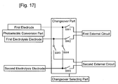
- the changeover part can electrically be connected to a second external circuit, and can make a changeover to a circuit that outputs the electromotive force inputted from the second external circuit to the first electrolysis electrode and the second electrolysis electrode to generate the first gas and the second gas respectively from the electrolytic solution.
- the first gas and the second gas can be produced by utilizing the electromotive force generated in the device.
- the solar-cell-integrated gas production device further includes a changeover selecting part that selects the circuit to be changed by the changeover part, and outputs the selected result to the changeover part, wherein the changeover part makes a changeover based upon the inputted result selected by the changeover selecting unit.
- the power supply and the production of the first gas the second gas can be switched according to the condition of the device, such as the amount of the solar irradiation irradiated to the photoelectric conversion part, and a demand condition, such as a power demand, of the facility provided with the device of the present invention.
- the changeover selecting part selects the circuit to be changed by the changeover part based upon at least one of a predicted amount of solar radiation irradiated to the device, a rainfall probability, time and date, ambient temperature, and a power demand estimate.
- the power supply to the first external circuit by the solar-cell-integrated gas production device according to the present invention and the production of the first gas and the second gas can be switched based upon at least one of a predicted amount of solar radiation irradiated to the device, a rainfall probability, time and date, ambient temperature, and a power demand estimate. Accordingly, the electromotive force generated in the photoelectric conversion part can effectively be utilized with zero waste.
- a solar-cell-integrated gas production device 25 comprises a photoelectric conversion part 2 having a light acceptance surface and its back surface; a first electrolysis electrode 8 formed on the back surface of the photoelectric conversion part 2 so as to be immersible into an electrolytic solution; a second electrolysis electrode 7 formed on the back surface of the photoelectric conversion part 2 so as to be immersible into an electrolytic solution; and a changeover part 10, wherein the first electrolysis electrode 8 and the second electrolysis electrode 7 are provided to be capable of generating a first gas and a second gas through an electrolysis of the electrolytic solution by utilizing an electromotive force generated by the photoelectric conversion part 2 irradiated with light, and the changeover part 10 changes a circuit that outputs the electromotive force, generated by irradiating the photoelectric conversion part 2 with light, to a first external circuit, and a circuit that outputs the electromotive force, generated by irradiating the photoelectric conversion part 2 with light, to the first electrolysis circuit 8 and the second electrolysis circuit
- the solar-cell-integrated gas production device 25 may also have a light-transmitting substrate 1, a second electrode 5, a first conductive part 9, an insulating part 11, a partition wall 13, a back substrate 14, an electrolytic solution chamber 15, a seal material 16, and a changeover selecting part 21.
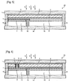
- the solar-cell-integrated gas production device 25 may have a cross-section illustrated in Fig. 2 , and may have a cross-section illustrated in Figs. 5, 6 , 7, 8 , 9 , 10, 11, or 12 .
- Figs. 5 to 8 correspond to cross-sectional views taken along a dotted line A - A in Fig. 1 .
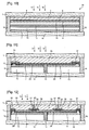
- Figs. 9 to 12 correspond to cross-sectional views taken along the dotted line A - A in Fig. 1 , although the position of the partition wall 13 or other members is different.
- the light-transmitting substrate 1 is not particularly limited, so long as it is a substrate having light translucency.
- Materials for the light-transmitting substrate 1 include transparent rigid materials such as soda glass, quartz glass, Pyrex (registered trademark), and synthetic quartz plate, a transparent resin plate, and a film material.
- a glass substrate is preferably used because it is chemically and physically stable.
- the surface of the light-transmitting substrate 1 on the side of the photoelectric conversion part 2 may have a fine concavo-convex structure so that the incident light can be effectively irregularly reflected on the surface of the photoelectric conversion part 2.
- This fine concavo-convex structure can be formed by a well-known method such as a reactive ion etching (RIE) process or a blast process.
- RIE reactive ion etching
- the first electrode 4 can be provided on the light-transmitting substrate 1, and can be provided so as to be in contact with the light acceptance surface of the photoelectric conversion part 2. In addition, the first electrode 4 can electrically be connected to the changeover part 10. Alternatively, the first electrode 4 may electrically be connected to the second electrolysis electrode 7 through the first conductive part 9 as illustrated in Figs. 6 , 7, and 9 , or may electrically be connected to the second electrolysis electrode 7 as illustrated in Fig. 8 . In addition, the first electrode 4 may have translucency.
- the first electrode 4 can be eliminated.
- the first electrode 4 By providing the first electrode 4, a larger current flows between the light acceptance surface of the photoelectric conversion part 2 and the changeover part 10.
- the first electrode 4 is electrically connected to the second electrolysis electrode 7 through the first conductive part 9 as illustrated in Figs. 6 , 7, and 9 , the electromotive force generated by the photoelectric conversion part 2 can efficiently be outputted to the first electrolysis electrode 8 and the second electrolysis electrode 7.
- the first electrode 4 may be formed of a transparent conductive film made of ITO or SnO 2 , or may be formed of a finger electrode made of a metal such as Ag or Au.
- the first electrode 4 may also be made of an electrode formed by combining the transparent conductive film and the metallic finger electrode.
- the first electrode 4 is formed of the transparent conductive film.
- the transparent conductive film is used to easily connect the light acceptance surface of the photoelectric conversion part 2 to the changeover part 10.
- the transparent electrode may be made of In-Zn-O (IZO), In-Sn-O (ITO), ZnO-Al, Zn-Sn-O, or SnO 2 .
- the transparent conductive film preferably has a sunlight transmittance of 85% or more, more preferably 90% or more, and most preferably 92% or more. In this case, the photoelectric conversion part 2 can efficiently absorb light.
- the transparent conductive film may be formed in a well-known method such as the sputtering method, the vacuum deposition method, the sol-gel method, the cluster beam deposition method, or the PLD (Pulse Laser Deposition) method.
- a well-known method such as the sputtering method, the vacuum deposition method, the sol-gel method, the cluster beam deposition method, or the PLD (Pulse Laser Deposition) method.
- the photoelectric conversion part 2 can be provided on the light-transmitting substrate 1, and causes a potential difference when irradiated with light.
- the photoelectric conversion part 2 may be the one generating the potential difference between the light acceptance surface and the back surface as illustrated in Figs. 2 , and 5 to 10 , or may be the one generating the potential difference between a first region and a second region on the back surface of the photoelectric conversion part 2 as illustrated in Figs. 11 and 12 .
- the photoelectric conversion part 2 may be a photoelectric conversion part using a silicon base semiconductor, a photoelectric conversion part using a compound semiconductor, a photoelectric conversion part using a dye sensitizer, or a photoelectric conversion part using an organic thin film.
- the photoelectric conversion part 2 has to be made of a material which generates the electromotive force required for generating the first gas and the second gas in the first electrolysis electrode 8 and the second electrolysis electrode 7, respectively, by receiving light.
- the photoelectric conversion part 2 When one of the first gas and the second gas is the hydrogen gas, and the other is the oxygen gas, the photoelectric conversion part 2 has to generate the electromotive force required for generating the hydrogen gas and the oxygen gas in the first electrolysis electrode 8 and the second electrolysis electrode 7, respectively, through the decomposition of water contained in the electrolytic solution.
- a potential difference between the first electrolysis electrode 8 and the second electrolysis electrode 7 needs to be more than a theoretic voltage (1.23 V) required for water decomposition, so that it is necessary to generate the sufficiently large potential difference in the photoelectric conversion part 2. Therefore, the photoelectric conversion part 2 is preferably provided such that the part (photoelectric conversion layer 28) to generate the electromotive force is formed of two or more junctions such as pn junctions connected in series.
- a method of connecting the photoelectric conversion layers 28 in series is not particularly limited.
- the photoelectric conversion layers 28 may be stacked and connected in series.
- the photoelectric conversion layers 28 that are arranged side by side may be connected in series with a third conductive part 33 as illustrated in Figs. 9 and 12 .
- the third conductive part 33 may include a light-transmitting electrode 30 and a back electrode 31 as illustrated in Fig. 9 .
- Materials for the photoelectric conversion include materials provided based on a silicon base semiconductor, a compound semiconductor, and an organic material, and any photoelectric conversion material can be used.
- the above photoelectric conversion materials may be laminated.
- a multi-junction structure may be made of the same material. In a case where the plurality of photoelectric conversion layers having different optical bandgaps are laminated to complement low-sensitive wavelength regions of the photoelectric conversion layers to each other, the incident light can be efficiently absorbed over a large wavelength region.
- a conductor such as a transparent conductive film may be interposed between the layers.
- the photoelectric conversion part 2 can be prevented from deteriorating.
- the photoelectric conversion part 2 using the silicon base semiconductor may be of a monocrystalline type, a polycrystalline type, an amorphous type, a spherical silicon type, or a combination of those.
- a pn junction between a p-type semiconductor and an n-type semiconductor can be provided in any one of these types.
- a pin junction in which an i-type semiconductor is provided between the p-type semiconductor and the n-type semiconductor can be provided.
- a plurality of pn junctions, a plurality of pin junctions, or the pn junction and pin junction may be provided.
- the silicon base semiconductor is the semiconductor containing silicon series such as silicon, silicon carbide, or silicon germanium. In addition, it may include the one in which an n-type impurity or a p-type impurity is added to silicon, and may include a crystalline, amorphous, or microcrystalline semiconductor.
- the photoelectric conversion part 2 using the silicon base semiconductor may be a thin-film or thick-film photoelectric conversion layer formed on the substrate 1, the one in which the pn junction or the pin junction is formed on a wafer such as a silicon wafer, or the one in which the thin-film photoelectric conversion layer is formed on a wafer having the pn junction or the pin junction.
- a first conductivity type semiconductor layer is formed on the first electrode 4 laminated on the light-transmitting substrate 1 by a method such as a plasma CVD method.
- This first conductivity type semiconductor layer is a p+-type or n+-type amorphous Si thin film, or a polycrystalline or microcrystalline Si thin film doped such that an impurity atom concentration is 1 ⁇ 10 18 to 5 ⁇ 10 21 /cm 3 .
- the material for the first conductivity type semiconductor layer is not limited to Si, and a compound such as SiC, SiGe, or Si X O 1-X may be used.
- a polycrystalline or microcrystalline Si thin film is formed as a crystalline Si base photoactive layer, on the first conductivity type semiconductor layer formed as described above by a method such as the plasma CVD method.
- the conductivity type is the first conductivity type whose doping concentration is lower than that of the first conductivity type semiconductor layer, or an i type.
- the material for the crystalline Si base photoactive layer is not limited to Si, and a compound such as SiC, SiGe, or Si X O 1-X may be used.
- a second conductivity type semiconductor layer whose conductivity type is opposite to that of the first conductivity type semiconductor layer is formed by a method such as the plasma CVD method.
- This second conductivity type semiconductor layer is an n+-type or p+-type amorphous Si thin film, or a polycrystalline or microcrystalline Si thin film doped with an impurity atom with 1 ⁇ 10 18 to 5 ⁇ 10 21 /cm 3 .
- the material for the second conductivity type semiconductor layer is not limited to Si, and a compound such as SiC, SiGe, or Si X O 1-X may be used.
- a substantially i-type amorphous Si base thin film can be inserted between the crystalline Si base photoactive layer and the second conductivity type semiconductor layer.
- the photoelectric conversion layer which is closest to the light acceptance surface.
- a second photoelectric conversion layer is formed.
- the second photoelectric conversion layer is formed of a first conductivity type semiconductor layer, a crystalline Si base photoactive layer, and a second conductivity type semiconductor layer, and they are formed in the same manners correspondingly as the first conductivity type semiconductor layer, the crystalline Si base photoactive layer, and the second conductivity type semiconductor layer in the first photoelectric conversion layer.
- a crystallization volume fraction of the crystalline Si base photoactive layer in the second photoelectric active layer is preferably higher than that of the crystalline Si base photoactive layer in the first layer.
- its crystallization volume fraction is preferably higher than that of the lower layer. This is because absorption is high in a long-wavelength region, and spectral sensitivity is shifted to the long-wavelength region side, so that sensitivity can be improved over a large wavelength region even when the photoactive layer is made of the same Si material. That is, when the tandem structure is made of Si having different crystallinities, the spectral sensitivity becomes high, so that the light can be used with high efficiency. At this time, the material having a low crystallinity has to be provided on the side of the light acceptance surface to implement high light use efficiency. In addition, when the crystallinity is 40% or less, an amorphous component increases, and deterioration is generated.
- a pn junction is formed using GaP, GaAs, InP, or InAs formed of III-V group elements, CdTe/CdS formed of II-VI group elements, or CIGS (Copper Indium Gallium DiSelenide) formed of I-III-VI group elements.
- a method for producing the photoelectric conversion part 2 using the compound semiconductor is shown below as one example, and in this method, film forming processes and the like are all sequentially performed with an MOCVD (Metal Organic Chemical Vapor Deposition) device.
- MOCVD Metal Organic Chemical Vapor Deposition
- a material for the III group element an organic metal such as trimethylgallium, trimethylaluminum, or trimethylindium is supplied to a growth system using hydrogen gas as a carrier gas.
- a gas such as arsine (AsH 3 ), phosphine (PH 3 ), or stibine (SbH 3 ) is used.
- a p-type impurity or n-type impurity dopant diethylzinc or the like is used to make the p type, or silane (SiH 4 ), disilane (Si 2 H 6 ), hydrogen selenide (H 2 Se), or the like is used to make the n type.
- SiH 4 silane
- Si 2 H 6 disilane
- H 2 Se hydrogen selenide
- a composition of the grown layer can be controlled by an introduced gas composition, and a film thickness thereof can be controlled by an introduction time length of the gas.
- the photoelectric conversion part is provided as the multi-junction laminated layers, the grown layers can be excellent in crystalline property by matching lattice constants between the layers as much as possible, so that photoelectric conversion efficiency can be improved.
- a well-known window layer may be provided on the side of the light acceptance surface or a well-known electric field layer may be provided on the side of a non-light acceptance surface, in addition to the part in which the pn junction is formed.
- a buffer layer may be provided to prevent the impurity from being diffused.
- the photoelectric conversion part using the dye sensitizer is mainly formed of a porous semiconductor, a dye sensitizer, an electrolyte, and a solvent, for example.
- one kind or more can be selected from well-known semiconductors made of titanium oxide, tungsten oxide, zinc oxide, barium titanate, strontium titanate, cadmium sulfide, and the like.
- Methods for forming the porous semiconductor on the substrate include a method in which a paste containing semiconductor particles is applied by a method such as a screen printing method or an ink-jet method and is dried or baked, a method in which a film is formed by a method such as the CVD method using a raw material gas, a PVD method, a deposition method, a sputtering method, a sol-gel method, and a method using an electrochemical redox reaction.
- a dye molecule contains a group such as a carboxylic acid group, a carboxylic acid anhydride group, an alkoxy group, a sulfonic acid group, a hydroxyl group, a hydroxylalkyl group, an ester group, a mercapto group, or a phosphoryl group.
- a group such as a carboxylic acid group, a carboxylic acid anhydride group, an alkoxy group, a sulfonic acid group, a hydroxyl group, a hydroxylalkyl group, an ester group, a mercapto group, or a phosphoryl group.
- Dyes containing the functional groups include a ruthenium bipyridine series dye, quinone series dye, quinonimine seriese dye, azo series dye, quinacridone series dye, squarylium series dye, cyanine series dye, merocyanine series dye, triphenylmethane series dye, xanthine series dye, porphyrin series dye, phthalocyanine series dye, perylene series dye, indigo series dye, and naphthalocyanine series dye.
- Methods for adsorbing the dye to the porous semiconductor include a method in which the porous semiconductor is dipped in a solution including the dye dissolved therein (dye adsorbing solution).
- the solvents used in the dye adsorbing solution are not limited in particular as long as they can dissolve the dye, and more specifically include alcohol such as ethanol or methanol, ketone such as acetone, ether such as diethylether or tetrahydrofuran, a nitrogen compound such as acetonitrile, aliphatic hydrocarbon such as hexane, aromatic hydrocarbon such as benzene, ester such as ethyl acetate, and water.
- the electrolyte is formed of a redox pair, and a liquid or a solid medium such as a polymer gel for holding the redox pair.
- a metal such as iron series or cobalt series, or a halogen substance such as chlorine, bromine, or iodine is preferably used, and a combination of metallic iodide such as lithium iodine, sodium iodine, or potassium iodine, and iodine is preferably used.
- an imidazole salt such as dimethyl-propyl-imidazole-iodide may be mixed therein.
- the solvent while a carbonate compound such as propylene carbonate, a nitrile compound such as acetonitrile, alcohol such as ethanol or methanol, water, a polar aprotic substance, or the like is used, among them, the carbonate compound or the nitrile compound is preferably used.
- a carbonate compound such as propylene carbonate, a nitrile compound such as acetonitrile, alcohol such as ethanol or methanol, water, a polar aprotic substance, or the like is used, among them, the carbonate compound or the nitrile compound is preferably used.
- the photoelectric conversion part using the organic thin film may be an electron hole transport layer formed of an organic semiconductor material having an electron-donating property and an electron-accepting property, or lamination of an electron transport layer having the electron-accepting property and a hole transport layer having the electron-donating property.
- the organic semiconductor material having the electron-donating property is not limited in particular as long as it has a function as an electron donor, it is preferable that a film can be formed by a coating method, and especially, a conductive polymer having the electron-donating property is preferably used.
- the conductive polymer means a ⁇ -conjugated polymer formed of a ⁇ -conjugated system in which a double bond or triple bond containing carbon-carbon or a heteroatom is adjacent to a single bond alternately, while showing a semiconducting property.
- the material for the conductive polymer having the electron-donating property may be polyphenylene, polyphenylenevinylene, polythiophene, polycarbazole, polyvinyl carbazole, polysilane, polyacetylene, polypyrrole, polyaniline, polyfluorene, polyvinyl pyrene, polyvinyl anthracene, a derivative or a copolymer thereof, a phthalocyanine-containing polymer, a carbazole-containing polymer, an organometallic polymer, or the like.
- a preferably used material may be tiophene-fluorene copolymer, polyalkyl thiophne, phenyleneethynylene-phenylenevinylene copolymer, fluorene-phenylene vinylene copolymer, tiophene-phenylenevinylene copolymer, or the like.
- the material for the organic semiconductor having the electron-accepting property is not limited in particular as long as it has a function as an electron acceptor, it is preferable that a film can be formed by a coating method and especially, a conductive polymer having the electron-donating property is preferably used.
- the conductive polymers having the electron-accepting property may be polyphenylenevinylene, polyfluorene, a derivative or a copolymer thereof, carbon nanotube, fullerene, a derivative thereof, a polymer containing a CN group or a CF 3 group, and a CF 3 -substituted polymer thereof.
- an organic semiconductor material having the electron-accepting property doped with an electron donating compound, or an organic semiconductor material having the electron-donating property doped with an electron accepting compound may be used.
- a material for the conductive polymer having the electron-accepting property doped with the electron donating compound may be the above-described conductive polymer material having the electron-accepting property.
- the electron donating compound to be doped may be a Lewis base such as an alkali metal or an alkali earth metal such as Li, K, Ca, or Cs. The Lewis base acts as the electron donor.
- the material for the conductive polymer having the electron-donating property doped with the electron accepting compound may be the above-described conductive polymer material having the electron-donating property.
- the electron accepting compound to be doped may be a Lewis acid such as FeCl 3 , AlCl 3 , AlBr 3 , AsF 6 , or a halogen compound. The Lewis acid acts as the electron acceptor.
- a method of forming the photoelectric conversion part 2 for generating the electromotive force between the first and second regions on the back surface there is a method in which a semiconductor wafer is used as a material, and a p-type semiconductor part 36 and an n-type semiconductor part 37 are formed in such a manner that a part of the p-type semiconductor part 36 and a part of the n-type semiconductor part 37 are formed respectively on the back surface of the semiconductor wafer, as illustrated in Figs. 11 and 12 .
- a pn junction can be formed on the photoelectric conversion part 2.
- the photoelectric conversion part 2 having an npp + junction can be formed, and when a semiconductor wafer made of an n-type semiconductor is used, the photoelectric conversion part 2 having a pnn + junction can be formed.
- one p-type semiconductor part 36 and one n-type semiconductor part 37 can be formed on the semiconductor wafer, or one of the p-type semiconductor part 36 and the n-type semiconductor part 37 can be formed in plural numbers. Alternatively, one of the p-type semiconductor part 36 and the n-type semiconductor part 37 may be formed on one portion of the semiconductor wafer, and the other may be formed on both sides thereof.
- the above photoelectric conversion part 2 receives sunlight and performs the photoelectric conversion, it can be irradiated, depending on applications, with artificial light such as light emitted from a fluorescent lamp, an incandescent lamp, an LED, or a specific heat source to perform the photoelectric conversion.
- the second electrode 5 can be provided on the back surface of the photoelectric conversion part 2, and can electrically be connected to the changeover part 10.
- the second electrode 5 can also be electrically connected to the first electrolysis electrode 8 as illustrated in Figs. 5 , and 7 to 11.
- the first electrolysis electrode 8 When the first electrolysis electrode 8 is provided on the back surface of the photoelectric conversion part 2 as illustrated in Figs. 5 , 7 , 8 , and 10 , the first electrolysis electrode 8 has the function same as that of the second electrode 5, so that the second electrode 5 can be eliminated.
- the second electrode 5 By providing the second electrode 5, a large current can flow between the back surface of the photoelectric conversion part 2 and the changeover part 10.
- the second electrode 5 is electrically connected to the first electrolysis electrode 8 as illustrated in Figs. 5 , and 7 to 10 , the electromotive force generated by the photoelectric conversion part 2 can efficiently be outputted to the first electrolysis electrode 8 and the second electrolysis electrode 7.
- the second electrode 5 is not limited in particular as long as it has conductivity, it may be a metal thin film, such as a thin film made of Al, Ag, or Au.
- the film can be formed by a sputtering method or the like.
- it may be a transparent conductive film made of a material such as In-Zn-O (IZO), In-Sn-O (ITO), ZnO-Al, Zn-Sn-O, or SnO 2 .
- the insulation part 11 can be provided between the second electrode 5 and the first and second electrolysis electrodes 8 and 7 as illustrated in Figs. 2 and 6 .
- the formation of the insulation part 11 can prevent a structure in which the second electrode 5 and the first and second electrolysis electrodes 8 and 7 are electrically connected not through the changeover part 10. By virtue of this, when the electromotive force generated by the irradiation of the photoelectric conversion part 2 with light is outputted to the first external circuit, a flow of a leak current through the first electrolysis electrode 8 and the second electrolysis electrode 7 can be prevented.
- the insulation part 11 may be provided between the second electrode 5 and the second electrolysis electrode 7 as illustrated in Figs. 5 , 7, and 8 . This configuration can prevent that the second electrolysis electrode 7 is electrically connected to the second electrode 5 not through the changeover part 10, thereby being capable of preventing the flow of the leak current.
- the insulation part 11 may be provided between the photoelectric conversion layers 28, which are connected in series, and the second electrolysis electrode 7 as illustrated in Fig. 9 , or may be provided between the photoelectric conversion part 2 and the first and second electrolysis electrodes 8 and 7 excluding the portion where the first electrolysis electrode 8 and the first region are electrically connected, and the portion where the second electrolysis electrode 7 and the second region are electrically connected, as illustrated in Figs. 11 and 12 .
- the insulation part 11 can be formed to cover the side face of the photoelectric conversion part 2 as illustrated in Figs. 8 and 9 .
- the second electrolysis electrode 7 or the first conductive part 9 can be formed on the insulation part 11 covering the side face of the photoelectric conversion part 2, whereby the occurrence of the leak current can be prevented, even if the second electrolysis electrode 7 or the first conductive part 9 is formed to be in contact with the first electrode 4.
- the insulation part 11 can be made of either an organic material or an inorganic material, and the organic material may be an organic polymer such as polyamide, polyimide, polyarylene, an aromatic vinyl compound, a fluorine series polymer, an acrylic series polymer, or a vinyl amide series polymer, while the inorganic material may be a metal oxide such as Al 2 O 3 , SiO 2 such as a porous silica film, a fuluoridated silicon oxide film (FSG), SiOC, an HSQ (Hydrogen Silsesquioxane) film, SiNx, or silanol (Si (OH) 4 ).
- the organic material may be an organic polymer such as polyamide, polyimide, polyarylene, an aromatic vinyl compound, a fluorine series polymer, an acrylic series polymer, or a vinyl amide series polymer
- the inorganic material may be a metal oxide such as Al 2 O 3 , SiO 2 such as a porous silica film, a fulu
- a method for forming the insulation part 11 may be a method in which a paste containing an insulation material is applied by a screen printing method, inkjet method, or spin coating method and then dried or baked, a method in which a film is formed by a method such as the CVD method using a raw material gas, PVD method, deposition method, sputtering method, or sol-gel method.
- the first conductive part 9 can electrically connect the second electrolysis electrode 7 and the first electrode 4 as illustrated in Figs. 6 , 7, and 9 .
- the second electrolysis electrode 7 can be formed on the back surface of the photoelectric conversion part 2, and the second electrolysis electrode 7 can be electrically connected to the first electrode 4.
- the first conductive part 9 can be in contact with the first electrode 4 which is in contact with the light acceptance surface of the photoelectric conversion part 2 and the second electrolysis electrode 7 provided on the back surface of the photoelectric conversion part 2, so that when the cross-sectional area of the first conductive part 9 which is parallel with the light acceptance surface of the photoelectric conversion part 2 is too large, an area of the light acceptance surface of the photoelectric conversion part 2 becomes small.
- the cross-sectional area of the first conductive part 9 which is parallel with the light acceptance surface of the photoelectric conversion part 2 is too small, a difference is generated between the potential of the light acceptance surface of the photoelectric conversion part 2 and the potential of the second electrolysis electrode 7, so that the potential difference required for electrolyzing the electrolytic solution could not be provided and generation efficiency of the first gas or the second gas could be lowered. Therefore, the cross-sectional area of the first conductive part 9 which is parallel to the light acceptance surface of the photoelectric conversion part 2 needs to be set within a certain range.
- the cross-sectional area of the first conductive part 9 which is parallel to the light acceptance surface of the photoelectric conversion part 2 (when the plurality of first conductive parts are provided, their total) may be 0.1% or more to 10% or less, preferably 0.5% or more to 8% or less, and more preferably 1% or more to 6% or less when it is assumed that the area of the light acceptance surface of the photoelectric conversion part 2 is 100%.
- the first conductive part 9 may be provided in a contact hole which penetrates the photoelectric conversion part 2.
- the decrease in area of the light acceptance surface of the photoelectric conversion part 2 because of the presence of the first conductive part 9 can be smaller.
- a current path between the light acceptance surface of the photoelectric conversion part 2 and the second electrolysis electrode 7 can be short, so that the first gas or the second gas can be generated more efficiently.
- the cross-sectional area of the first conductive part 9 which is parallel to the light acceptance surface of the photoelectric conversion part 2 can be easily adjusted.
- the second electrolysis electrode 7 and the first electrode 4 can be electrically connected through the first conductive part 9 formed on the contact hole penetrating the photoelectric conversion part 2, as illustrated in the sectional view of the solar-cell-integrated gas production device 25 according to the present embodiment in Figs. 6 and 7 .
- the number of the contact hole provided with the first conductive part 9 may be one or more, and the contact hole may have a circular cross-section.
- the cross-sectional area of the contact hole which is parallel to the light acceptance surface of the photoelectric conversion part 2 may be 0.1% or more to 10% or less, preferably 0.5% or more to 8% or less, and more preferably 1% or more to 6% or less when it is assumed that the area of the light acceptance surface of the photoelectric conversion part 2 is 100%.
- first conductive part 9 may be provided on the insulation part 11 that covers the side face of the photoelectric conversion part 2 as illustrated in Fig. 9
- a material for the first conductive part 9 is not limited in particular as long as it has conductivity.
- Methods include a method in which a paste containing conductive particles such as carbon paste or Ag paste is applied by a screen printing method, or inkjet method and then dried or baked, a method in which a film is formed by a method such as the CVD method using a raw material gas, PVD method, deposition method, sputtering method, sol-gel method, and method using electrochemical redox reaction.
- the second conductive part 29 may be provided between the insulation part 11 and the first electrolysis electrode 8, or between the insulation part 11 and the second electrolysis electrode 7.
- the first electrolysis electrode 8 may be electrically connected to the changeover part 10 through the second conductive part 29, or the second electrolysis electrode 7 may be electrically connected to the changeover part 10 or the first electrode 4 through the second conductive part 29 as illustrated in Fig. 9 .
- the first electrolysis electrode 8 and the second electrolysis electrode 7 may be electrically connected to the first region and the second region through the second conductive part 29, respectively.
- a material for the second conductive part 29 is not limited in particular as long as it has conductivity.
- Methods include a method in which a paste containing conductive particles such as carbon paste or Ag paste is applied by a screen printing method, or inkjet method and then dried or baked, a method in which a film is formed by a method such as the CVD method using a raw material gas, PVD method, deposition method, sputtering method, sol-gel method, and method using electrochemical redox reaction.
- the first electrolysis electrode 8 and the second electrolysis electrode 7 are respectively provided on the back surface of the photoelectric conversion part 2. By virtue of this configuration, the first electrolysis electrode 8 and the second electrolysis electrode 7 do not block the light incident on the photoelectric conversion part 2.
- the first electrolysis electrode 8 and the second electrolysis electrode 7 can be electrically connected to the changeover part 10.
- the first electrode 4 and the second electrode 5 can electrically be connected to the first electrolysis electrode 8 and the second electrolysis electrode 7, respectively, via the changeover part 10.
- the first electrolysis electrode 8 and the second electrolysis electrode 7 can be electrically connected to the light acceptance surface or the back surface of the photoelectric conversion part 2 through the changeover part 10.
- the electromotive force generated by the light incidence into the photoelectric conversion part 2 can be outputted to the first electrolysis electrode 8 and the second electrolysis electrode 7.
- One of the first electrolysis electrode 8 and the second electrolysis electrode 7 can be electrically connected to the changeover part 10.
- the solar-cell-integrated gas production device 25 according to the present embodiment has the cross-section illustrated in Figs. 5 and 10 , and has the electric circuit illustrated in Fig. 14
- the solar-cell-integrated gas production device 25 according to the present embodiment has the cross-section illustrated in Fig. 6 , and has the electric circuit illustrated in Fig. 15
- the light acceptance surface and the back surface of the photoelectric conversion part 2 can electrically be connected to the first electrolysis electrode 8 and the second electrolysis electrode 7.
- the electromotive force generated by the light incidence into the photoelectric conversion part 2 can be outputted to the first electrolysis electrode 8 and the second electrolysis electrode 7.
- the solar-cell-integrated gas production device 25 has the cross-section illustrated in Fig. 10
- the second electrode 5 can be eliminated, and the electric circuit can be the one illustrated in Fig. 17 .
- the first electrolysis electrode 8 and the second electrolysis electrode 7 can be electrically connected to the second electrode 5 and the first electrode 4, respectively.
- the solar-cell-integrated gas production device 25 has the cross-section illustrated in Figs. 7, 8, and 9 , and has the electric circuit illustrated in Fig. 16
- the light acceptance surface and the back surface of the photoelectric conversion part 2 can electrically be connected to the first electrolysis electrode 8 and the second electrolysis electrode 7.
- the electromotive force generated by the light incidence into the photoelectric conversion part 2 can be outputted to the first electrolysis electrode 8 and the second electrolysis electrode 7.
- the solar-cell-integrated gas production device 25 has the cross-section illustrated in Figs.
- the solar-cell-integrated gas production device may have an electric circuit in which the first electrode illustrated in Fig. 16 can be the second conductive part 29 provided between the second electrolysis electrode 7 and the photoelectric conversion part 2, and the second electrode illustrated in Fig. 16 can be the second conductive part 29 provided between the first electrolysis electrode 8 and the photoelectric conversion part 2.
- the first electrolysis electrode 8 and the second electrolysis electrode 7 are provided to be immersible into the electrolytic solution. This can progress the electrolysis reaction of the electrolytic solution on the surface of the first electrolysis electrode 8 and the second electrolysis electrode 7, whereby the first gas and the second gas can be generated.
- One of the first gas and the second gas can be hydrogen gas, and the other can be oxygen gas.
- the first electrolysis electrode 8 and the second electrolysis electrode 7 can be provided not to be in contact with each other. This configuration can prevent the leak current from flowing between the first electrolysis electrode 8 and the second electrolysis electrode 7.
- One of the first electrolysis electrode 8 and the second electrolysis electrode 7 may be a hydrogen generation part that generates H 2 from the electrolytic solution, and the other may be an oxygen generation part that generates O 2 from the electrolytic solution.
- the solar-cell-integrated gas production device can decompose water contained in the electrolytic solution so as to generate hydrogen gas and oxygen gas, which serve as the fuel of the fuel cell.
- the hydrogen generation part is the part to generate H 2 from the electrolytic solution, and it is the first electrolysis electrode 8 or the second electrolysis electrode 7.
- the hydrogen generation part may contain a catalyst for the reaction to generate H 2 from the electrolytic solution. In this case, the reaction rate to generate H 2 from the electrolytic solution can increase.
- the hydrogen generation part may be formed of only the catalyst for the reaction to generate H 2 from the electrolytic solution, and the catalyst may be supported by a carrier.
- the hydrogen generation part may have a catalytic surface area larger than the area of the light acceptance surface of the photoelectric conversion part 2. In this case, the reaction rate to generate H 2 from the electrolytic solution can become higher.
- the hydrogen generation part may be a catalyst-supporting porous conductor.
- the catalytic surface area can increase.
- the potential can be prevented from varying due to the current flowing between the light acceptance surface or the back surface of the photoelectric conversion part 2 and the catalyst contained in the hydrogen generation part.
- the hydrogen generation part may contain at least one of Pt, Ir, Ru, Pd, Rh, Au, Fe, Ni, and Se as a hydrogen generation catalyst.
- the catalyst for the reaction to generate H 2 from the electrolytic solution is provided to promote conversion from two protons and two electrons to one hydrogen molecule, and can be made of a material which is chemically stable and having a small hydrogen generation overvoltage.
- the hydrogen generation catalyst include: a platinum group metal such as Pt, Ir, Ru, Pd, Rh, or Au having a catalytic activity for hydrogen, an alloy thereof, and a compound containing the platinum group metal; and an alloy containing any of metals such as Fe, Ni and Se constituting an activity center of a hydrogenase as a hydrogen generating enzyme, and a compound containing the metal, and these examples and combinations thereof can be desirably used as the hydrogen generation catalyst.
- Pt and a nanostructured body containing Pt are preferably used because their hydrogen generation overvoltage is low.
- a material such as CdS, CdSe, ZnS, or ZrO 2 which generate the hydrogen generation reaction by light irradiation can be also used.
- the hydrogen generation catalyst can be supported on a conductor in order to increase the reaction area more to improve the gas generation rate.
- a conductor in order to increase the reaction area more to improve the gas generation rate.
- the conductor to support the catalyst it may be a metal material, a carbonaceous material, or an inorganic material having conductivity.
- the metal material is preferably a material having electron conductivity and having corrosion resistance under an acidic atmosphere. More specifically, the material may be a noble metal such as Au, Pt, or Pd, a metal such as Ti, Ta, W, Nb, Ni, Al, Cr, Ag, Cu, Zn, Su, or Si, a nitride and carbide of the above metal, a stainless steel, or an alloy such as Cu-Cr, Ni-Cr, or Ti-Pt.
- the metal material more preferably contains at least one element selected from a group including Pt, Ti, Au, Ag, Cu, Ni, and W because another chemical side reaction is hardly generated. This metal material is relatively low in electric resistance and can prevent a voltage from being lowered even when a current is drawn in a surface direction.
- a surface of the metal material having the poor corrosion resistance may be coated with a noble metal or metal having the corrosion resistance such as Au, Pt, or Pd, carbon, graphite, glassy carbon, a conductive polymer, conductive nitride, conductive carbide, or conductive oxide.
- a noble metal or metal having the corrosion resistance such as Au, Pt, or Pd, carbon, graphite, glassy carbon, a conductive polymer, conductive nitride, conductive carbide, or conductive oxide.
- the carbonaceous material it is preferable that it is chemically stable and has conductivity.
- the material may be carbon powder or carbon fiber such as acetylene black, vulcanized fiber, ketjen black, furnace black, VGCF, carbon nanotube, carbon nanohorn, or fullerene.
- the inorganic material having the conductivity may be In-Zn-O (IZO), In-Sn-O (ITO), ZnO-Al, Zn-Sn-O, SnO 2 , or antimony oxide doped tin oxide.
- IZO In-Zn-O
- ITO In-Sn-O
- ZnO-Al ZnO-Al
- Zn-Sn-O SnO 2
- antimony oxide doped tin oxide antimony oxide doped tin oxide
- the conductive polymer may be polyacethylene, polythiophene, polyaniline, polypyrrole, polyparaphenylene, or polyparaphenylenevinylene
- the conductive nitride it may be carbon nitride, silicon nitride, gallium nitride, indium nitride, germanium nitride, titanium nitride, zirconium nitride, or thallium nitride
- the conductive carbide it may be tantalum carbide, silicon carbide, zirconium carbide, titanium carbide, molybdenum carbide, niobium carbide, iron carbide, nickel carbide, hafnium carbide, tungsten carbide, vanadium carbide, or chrome carbide
- the conductive oxide it may be tin oxide, indium tin oxide (ITO), or antimony oxide doped tin oxide.
- a structure of the conductor to support the hydrogen generation catalyst may be preferably selected from a plate shape, foil shape, rod shape, mesh shape, lath plate shape, porous plate shape, porous rod shape, woven cloth shape, unwoven cloth shape, fiber shape, and a felt shape.
- the conductor having a groove formed by being pressed in a surface of a felt-shape electrode is preferably used because it can reduce electric resistance and flow resistance of an electrode liquid.
- the oxygen generation part is the part to generate O 2 from the electrolytic solution, and it is the first electrolysis electrode 8 or the second electrolysis electrode 7.
- the oxygen generation part may contain a catalyst for the reaction to generate O 2 from the electrolytic solution. In this case, the reaction rate to generate O 2 from the electrolytic solution can increase.
- the oxygen generation part may be formed of only the catalyst for the reaction to generate O 2 from the electrolytic solution, and the catalyst may be supported by a carrier.
- the oxygen generation part may have a catalytic surface area larger than the area of the light acceptance surface of the photoelectric conversion part 2. In this case, the reaction rate to generate O 2 from the electrolytic solution can increase.
- the oxygen generation part may be a catalyst-supporting porous conductor.
- the catalytic surface area can increase.
- the potential can be prevented from varying due to the current flowing between the light acceptance surface or the back surface of the photoelectric conversion part 2 and the catalyst contained in the oxygen generation part.
- the oxygen generation part may contain at least one of Mn, Ca, Zn, Co, and Ir, as an oxygen generation catalyst.
- the catalyst for the reaction to generate O 2 from the electrolytic solution is provided to promote conversion from two water molecules to one oxygen, four protons and four electrons, and made of a material which is chemically stable and having a small oxygen generation overvoltage.
- the materials include an oxide or compound containing Mn, Ca, Zn or Co serving as an active center of Photosystem II which is an enzyme to catalyze the reaction to generate oxygen from water using light, a compound containing a platinum group metal such as Pt, RuO 2 , or IrO 2 , an oxide or a compound containing a transition metal such as Ti, Zr, Nb, Ta, W, Ce, Fe, or Ni, and a combination of the above materials.
- an iridium oxide, manganese oxide, cobalt oxide, or cobalt phosphate is preferably used because an overvoltage is low and oxygen generation efficiency is high.
- the oxygen generation catalyst can be supported on a conductor in order to increase the reaction area more, and to increase the gas generation rate.
- a conductor As the conductors to support the catalyst, it may be a metal material, a carbonaceous material, or an inorganic material having conductivity. Their explanations are relevant to those described for the hydrogen generation part in "9. Hydrogen generation part" as long as there is no inconsistency.
- an auxiliary catalyst may be used, such as an oxide of Ni, Cr, Rh, Mo, Co, or Se or a compound of them.
- a method for supporting the hydrogen generation catalyst and the oxygen generation catalyst may be a method performed by directly applying it to the conductor or the semiconductor, a PVD method such as a vapor deposition method, sputtering method, or ion plating method, a dry coating method such as a CVD method, or an electro-crystallization method, depending on the material.
- a PVD method such as a vapor deposition method, sputtering method, or ion plating method
- a dry coating method such as a CVD method
- electro-crystallization method depending on the material.
- the catalyst is supported on a porous body, a fibrous substance or a nanoparticle of metal or carbon, to increase the reaction surface area, whereby the hydrogen and oxygen generation rate can be improved.
- the changeover part 10 can change the circuit that outputs the electromotive force, generated by irradiating the photoelectric conversion part 2 with light, to the first external circuit, and the circuit that outputs the electromotive force, generated by irradiating the photoelectric conversion part 2 with light, to the first electrolysis electrode 8 and the second electrolysis electrode 7 so as to generate the first gas and the second gas respectively from the electrolytic solution.
- the electromotive force generated by irradiating the photoelectric conversion part 2 with light can be supplied to the first external circuit as power, and the first gas and the second gas can be produced by using the electromotive force generated by irradiating the photoelectric conversion part 2 with light.
- the method of electrically connecting the changeover part 10 with the first external circuit is not limited in particular.
- the changeover part 10 may have an output terminal 22, and the changeover part 10 may be electrically connected to the first external circuit via the output terminal 22.
- the changeover part 10 can be electrically connected to the second external circuit, and it can make a changeover to the circuit that outputs the electromotive force, generated by irradiating the photoelectric conversion part 2 with light, to the first electrolysis electrode 8 and the second electrolysis electrode 7, so as to generate the first gas and the second gas respectively from the electrolytic solution.
- the first gas and the second gas can be produced from the electrolytic solution by utilizing the electromotive force inputted from the second external circuit.
- the method of electrically connecting the changeover part 10 with the second external circuit is not limited in particular.
- the changeover part 10 may have an input terminal 23, and the changeover part 10 may be electrically connected to the second external circuit via the input terminal 23.
- the changeover part 10 will be described in detail with reference to the drawings.
- the solar-cell-integrated gas production device 25 has the cross-section illustrated in Fig. 2 , and has the electric circuit illustrated in Fig. 13 , for example, the electromotive force generated by irradiating the photoelectric conversion part 2 with light can be outputted to the first external circuit, when a SW (switch) 1 and a SW 2 are turned ON, and a SW3 and a SW4 are turned OFF.
- the electromotive force generated by irradiating the photoelectric conversion part 2 with light can be outputted to the first electrolysis electrode 8 and the second electrolysis electrode 7.
- the electromotive force inputted from the second external circuit can be outputted to the first electrolysis electrode 8 and the second electrolysis electrode 7.
- the electromotive force generated by irradiating the photoelectric conversion part 2 with light and the electromotive force inputted from the second external circuit can both be outputted to the first electrolysis electrode 8 and the second electrolysis electrode 7.
- the electromotive force generated by irradiating the photoelectric conversion part 2 with light can be outputted to the first external circuit, when the SW 1 and the SW 2 are turned ON, and the SW3 and the SW4 are turned OFF.
- the electromotive force generated by irradiating the photoelectric conversion part 2 with light can be outputted to the first electrolysis electrode 8 and the second electrolysis electrode 7.
- the electromotive force inputted from the second external circuit can be outputted to the first electrolysis electrode 8 and the second electrolysis electrode 7.
- the electromotive force generated by irradiating the photoelectric conversion part 2 with light and the electromotive force inputted from the second external circuit can both be outputted to the first electrolysis electrode 8 and the second electrolysis electrode 7.
- the electromotive force generated by irradiating the photoelectric conversion part 2 with light can be outputted to the first external circuit, when the SW 1 and the SW 2 are turned ON, the SW3 and the SW4 are turned OFF, and the electromotive force generated by irradiating the photoelectric conversion part 2 with light does not reach the electrolysis voltage of the electrolytic solution.
- the electromotive force generated by irradiating the photoelectric conversion part 2 with light can be outputted to the first electrolysis electrode 8 and the second electrolysis electrode 7. Accordingly, even if the solar-cell-integrated gas production device 25 has the electric circuit illustrated in Fig.
- the circuit that outputs the electromotive force, generated by irradiating the photoelectric conversion part 2 with light, to the first external circuit, and the circuit that outputs the electromotive force, generated by irradiating the photoelectric conversion part 2 with light, to the first electrolysis electrode 8 and the second electrolysis electrode 7 can be switched by the changeover part 10.
- the solar-cell-integrated gas production device 25 may have an electric circuit in which the first electrode illustrated in Fig. 16 can be the second conductive part 29 provided between the second electrolysis electrode 7 and the photoelectric conversion part 2, and the second electrode illustrated in Fig. 16 can be the second conductive part 29 provided between the first electrolysis electrode 8 and the photoelectric conversion part 2.
- the changeover part 10 can input the result selected by a changeover selecting part 21, and can make a changeover of the circuit based upon the inputted selected result. Thus, the changeover part 10 can change the circuit to the circuit selected by the changeover selecting part 21.
- the changeover part 10 can also make a changeover of the circuit based upon the magnitude of the electromotive force generated by irradiating the photoelectric conversion part 2 with light. Therefore, when the power outputted to the first external circuit is generated in the photoelectric conversion part 2, the electromotive force generated in the photoelectric conversion part 2 can be outputted to the first external circuit, and when the power outputted to the first external circuit is not generated in the photoelectric conversion part 2, the electromotive force generated in the photoelectric conversion part 2 can be outputted to the first electrolysis electrode 8 and the second electrolysis electrode 7.
- the changeover part 10 can also make a changeover of the circuit based upon the magnitude of the electromotive force of the second external circuit. Therefore, when the power supplied from the second external circuit becomes larger than the electrical needs, the first gas and the second gas can be produced by utilizing the power supplied from the second external circuit.
- the changeover selecting part 21 can select the circuit to be changed by the changeover part 10, and can output the selected result to the changeover part 10. Thus, the changeover selecting part 21 can output a signal for allowing the changeover part 10 to make a changeover of the circuit according to a situation.
- the changeover selecting part 21 can select the circuit to be changed by the changeover part 10 based upon at least any one of a predicted amount of solar radiation irradiated to the solar-cell-integrated gas production device 25, a rainfall probability, time and date, ambient temperature, and a power demand estimate.
- the changeover selecting part 21 can also select the circuit to be changed by the changeover part 10 based upon the magnitude of the electromotive force generated by irradiating the photoelectric conversion part 2 with light or the magnitude of the electromotive force of the second external circuit. With this, the changeover selecting part 21 can select the circuit to be changed by the changeover part 10 so as to be most suitable for the circumstance.
- the solar-cell-integrated gas production device 25 can decompose the electrolytic solution to generate hydrogen and the like, since the changeover selecting part 21 selects the circuit that outputs the electromotive force generated in the photoelectric conversion part 2 to the first electrolysis electrode 8 and the second electrolysis electrode 7. Accordingly, the fuel cell can generate power by using the hydrogen gas, which is fully stored, as the fuel, whereby the power sufficiently satisfying the power demand can be supplied to the first external circuit.
- the changeover selecting part 21 can select the circuit that outputs the electromotive force generated in the photoelectric conversion part 2 to the first electrolysis electrode 8 and the second electrolysis electrode 7. With this, the solar-cell-integrated gas production device 25 can decompose the electrolytic solution to generate hydrogen gas and the like, whereby the facility can utilize heat by using a heat source that employs hydrogen gas as a fuel.
- the changeover selecting part 21 can select the circuit that outputs the electromotive force generated in the photoelectric conversion part 2 to the first electrolysis electrode 8 and the second electrolysis electrode 7. With this, the solar-cell-integrated gas production device 25 can decompose the electrolytic solution to generate hydrogen gas and the like, thereby being capable of storing energy as hydrogen gas.
- the factors for determining which circuit is selected by the changeover selecting part 21 described above may be plural. If there are plural factors, the changeover selecting part 21 can determine the circuit to be changed by comprehensively considering the plural factors for the determination.
- the changeover selecting part 21 can receive a signal transmitted from a domestic Smart meter, a signal transmitted from a power company, or a signal provided through an information network such as Internet, and can select the circuit to be changed by the changeover part 10 based upon the signal.
- the changeover selecting part 21 can receive the signal wiredly or wirelessly.
- the electrolytic solution chamber 15 is provided to be capable of storing the electrolytic solution into which the first electrolysis electrode 8 or the second electrolysis electrode 7 is immersed. With this configuration, the first electrolysis electrode 8 or the second electrolysis electrode 7 can be immersed into the electrolytic solution, and the electrolysis reaction of the electrolytic solution can be progressed on the surface of the first electrolysis electrode 8 and the second electrolysis electrode 7.
- the electrolytic solution chamber 15 can be a space between the first and second electrolysis electrodes 8 and 7 and the back substrate 14.
- the electrolytic solution chamber 15 can be a channel for collecting the first gas generated from the first electrolysis electrode 8 and the second gas generated from the second electrolysis electrode 7.
- the back substrate 14 can be provided over the first electrolysis electrode 8 and the second electrolysis electrode 7 so as to be opposed to the light-transmitting substrate 1.
- the back substrate 14 can be provided such that a space is provided between the first electrolysis electrode 8 or the second electrolysis electrode 7, and the back substrate 14. This space can be formed as the electrolytic solution chamber 15.
- the back substrate 14 can be a part of an outer case that can accommodate the photoelectric conversion part 2, the first electrolysis electrode 8, and the second electrolysis electrode 7, and can form the electrolytic solution chamber 15.
- the back substrate 14 constitutes the electrolytic solution chamber 15 and is provided to confine the generated hydrogen gas and oxygen gas, so that it is made of a material having high air leakage efficiency.
- the back substrate 14 is not limited to be transparent or opaque.
- the back substrate 14 may be a transparent rigid material such as quartz glass, Pyrex (registered trademark), or a synthetic quartz plate, a transparent resin plate, or a transparent resin film.
- the glass material is preferably used because it does not transmit a gas and it is stable chemically and physically.
- the outer case is used for the back substrate 14, it is preferable that the outer case is made of a steel material such as stainless steel, a ceramic such as zirconia or alumina, or a synthetic resin such as phenolic resin, melamine resin (MF), or glass-reinforced polyamide resin.
- a steel material such as stainless steel, a ceramic such as zirconia or alumina, or a synthetic resin such as phenolic resin, melamine resin (MF), or glass-reinforced polyamide resin.
- the partition wall 13 can be provided to separate the electrolytic solution chamber 15 that is a space between the first electrolysis electrode 8 and the back substrate 14, and the electrolytic solution chamber 15 that is a space between the second electrolysis electrode 7 and the back substrate 14.
- the first gas and the second gas generated in the first electrolysis electrode 8 and the second electrolysis electrode 7 are prevented from being mixed, so that the first gas and the second gas can be separately collected.
- the partition wall 13 may contain an ion exchanger. In this case, it can equalize an ion concentration which became unbalanced between the electrolytic solution in the electrolytic solution chamber 15 between the first electrolysis electrode 8 and the back substrate 14, and the electrolytic solution in the electrolytic solution chamber 15 between the second electrolysis electrode 7 and the back substrate 14. That is, ions are moved through the partition wall 13 to eliminate the imbalance in ion concentration caused by the electrolysis reaction on the first electrolysis electrode 8 and the second electrolysis electrode 7. When hydrogen gas and oxygen gas are generated by the electrolysis reaction of H 2 O on the first electrolysis electrode 8 and the second electrolysis electrode 7, the imbalance in proton can be eliminated, if the partition wall 13 contains an ion exchanger.
- the partition wall 13 is preferably made of a material which transmits water.
- the partition wall 13 may be an inorganic film made of porous glass, porous zirconia, or porous alumina, or an ion exchanger.
- the ion exchanger may be any well-known ion exchanger, such as a proton-conducting film, cation-exchanging film, or anion-exchanging film.
- a material for the proton-conducting film is not limited in particular as long as it has proton-conducting and electrically insulating properties, such as a polymer film, inorganic film, or composite film.
- the polymer film may be a perfluoro sulfonate series electrolytic film such as Nafion (registered trademark) made by Du Pont, Aciplex (registered trademark) made by Asahi Kasei Corporation, or Flemion (registered trademark) made by Asahi Glass Co., Ltd., or a carbon hydride series electrolytic film formed of polystyrene sulfonate, sulfonated polyether ether ketone, or the like.
- a perfluoro sulfonate series electrolytic film such as Nafion (registered trademark) made by Du Pont, Aciplex (registered trademark) made by Asahi Kasei Corporation, or Flemion (registered trademark) made by Asahi Glass Co., Ltd.
- a carbon hydride series electrolytic film formed of polystyrene sulfonate, sulfonated polyether ether ketone, or the like.
- the inorganic film may be a film made of glass phosphate, cesium hydrogen sulfate, polytungsto phosphate, ammonium polyphosphate, or the like.
- the composite film is formed of an inorganic substance such as a sulfonated polyimide series polymer, or tungsten acid, and an organic substance such as polyimide, and more particularly, GORE-SELECT (registered trademark) made by Gore & Associates Inc., a pore-filling electrolytic film, or the like.
- the material when it is used in a high-temperature atmosphere (such as 100°C or more), the material may be sulfonated polyimide, 2-acrylamide-2-methylpropane sulfonate (AMPS), sulfonated polybenzimidazole, phosphonated polybenzimidazole, cesium hydrogen sulfate, ammonium polyphosphate, or the like.
- AMPS 2-acrylamide-2-methylpropane sulfonate
- sulfonated polybenzimidazole phosphonated polybenzimidazole
- cesium hydrogen sulfate cesium hydrogen sulfate
- ammonium polyphosphate or the like.
- the cation-exchanging film may be a solid polymer electrolyte which can move cation. More specifically, it may be a fluorine series ion-exchanging film such as a perfluoro carbon sulfonate film or perfluoro carbon carboxylic acid film, a poly-benz-imidazole film impregnated with phosphoric acid, a polystyrene sulfonate film, a sulfonated styrene-vinylbenzene copolymer film, or the like.
- fluorine series ion-exchanging film such as a perfluoro carbon sulfonate film or perfluoro carbon carboxylic acid film, a poly-benz-imidazole film impregnated with phosphoric acid, a polystyrene sulfonate film, a sulfonated styrene-vinylbenzene copolymer film, or the like.
- the anion-exchanging film is preferably used.
- a solid polymer electrolyte which can move anion can be used. More specifically, it may be a polyortho phenylenediamine film, a fluorine series ion-exchanging film having an ammonium salt derivative group, a vinylbenzene polymer film having an ammonium salt derivative group, a film aminated with chloromethylstyrene-vinylbenzene copolymer, or the like.
- the seal material 16 is the material to bond the light-transmitting substrate 1 and the back substrate 14, and to seal the electrolytic solution chamber 15. When the box-like back substrate 14 is employed, the seal material 16 is used to bond the box and the light-transmitting substrate 1.
- the seal material 16 is preferably an ultraviolet curing adhesive or a thermal curing adhesive, but its kind is not limited.
- the ultraviolet curing adhesive is a resin which polymerizes by being irradiated with a light having a wavelength of 200 to 400 nm and cures in several seconds after being irradiated, and is divided into a radical polymerization type and a cation polymerization type, and the radical polymerization type resin is formed of acrylate or unsaturated polyester, and the cation polymerization type is formed of epoxy, oxetane, or vinyl ether.
- the thermal curing polymer adhesive may be an organic resin such as a phenol resin, epoxy resin, melamine resin, urea resin, or thermal curing polyimide.
- the thermal curing polymer adhesive successfully bonds the members by being heated and polymerizing under a pressed condition at the time of thermal compression and then being cooled down to room temperature while kept being pressed, so that a fastening member is not needed.
- a hybrid material having high adhesion to the glass substrate can be used. By using the hybrid material, mechanical characteristics such as elasticity and hardness are improved, and thermal resistance and chemical resistance can be considerably improved.
- the hybrid material is formed of inorganic colloidal particles and an organic binder resin.
- it is formed of the inorganic colloidal particles such as silica, and the organic binder resin such as an epoxy resin, polyurethane acrylate resin, or polyester acrylate resin.
- the seal material 16 is shown, but this is not limited as long as it has a function to bond the substrate 1 and the back substrate 14, so that a method in which physical pressure is applied from the outside with a member such as a screw using a resin or metal gasket may be occasionally used to enhance the air tightness.
- the water intake 18 can be provided by opening a part of the seal material 16 in the solar-cell-integrated gas production device 25.
- the water intake 18 is arranged to supply the electrolytic solution to the electrolytic solution chamber 15, and its position and shape are not limited in particular as long as the electrolytic solution can be efficiently supplied to the solar-cell-integrated gas production device 25, but it is preferably provided at a lower part of the solar-cell-integrated gas production device 25 in view of flowability and easiness of supply.
- first gas exhaust opening 20 and the second gas exhaust opening 19 can be provided by opening the seal material 16 on an upper part of the solar-cell-integrated gas production device 25 after the solar-cell-integrated gas production device 25 has been set as being tilted.
- first gas exhaust opening 20 and the second gas exhaust opening 19 can be provided on the side of the first electrolysis electrode and on the side of the second electrolysis electrode across the partition wall 13, respectively.
- the solar-cell-integrated gas production device 25 can be set such that the light acceptance surface of the photoelectric conversion part 2 is tilted with respect to a horizontal surface under the condition that it faces upward, and the water intake 18 is positioned on the lower side, and the first gas exhaust opening 20 and the second gas exhaust opening 19 are positioned on the upper side.
- the electrolytic solution can be introduced from the water intake 18 into the solar-cell-integrated gas production device 25, and the electrolytic solution chamber 15 is filled with the electrolytic solution.
- the first gas and the second gas are sequentially generated in the first electrolysis electrode 8 and the second electrolysis electrode 7, respectively.
- the generated first gas and the second gas can be separated by the partition wall 13, and the first gas and the second gas rise to the upper part of the solar-cell-integrated gas production device 25 and are collected from the first gas exhaust opening 20 and the second gas exhaust opening 19.
- the electrolytic solution is the water solution containing the electrolyte such as an electrolytic solution containing 0.1M of H 2 SO 4 , or a buffering solution containing 0.1 M of potassium phosphate.
- the type of the electrolyte is not limited in particular, so long as the ion movement for the gas generation reaction is caused, and the concentration of the electrolyte is not limited in particular.
Landscapes
- Chemical & Material Sciences (AREA)
- Engineering & Computer Science (AREA)
- Organic Chemistry (AREA)
- Inorganic Chemistry (AREA)
- Power Engineering (AREA)
- Chemical Kinetics & Catalysis (AREA)
- Electrochemistry (AREA)
- Materials Engineering (AREA)
- Metallurgy (AREA)
- Computer Hardware Design (AREA)
- Physics & Mathematics (AREA)
- Condensed Matter Physics & Semiconductors (AREA)
- Electromagnetism (AREA)
- General Physics & Mathematics (AREA)
- Microelectronics & Electronic Packaging (AREA)
- Combustion & Propulsion (AREA)
- General Health & Medical Sciences (AREA)
- Health & Medical Sciences (AREA)
- Hybrid Cells (AREA)
- Photovoltaic Devices (AREA)
- Electrolytic Production Of Non-Metals, Compounds, Apparatuses Therefor (AREA)
- Fuel Cell (AREA)
Claims (9)
- Solarzellenintegrierte Gasproduktionsvorrichtung (25), die Folgendes umfasst:einen fotoelektrischen Wandlungsteil (2) mit einer Lichtannahmeseite und ihrer Rückseite;eine erste Elektrolyseelektrode (8), die auf der Rückseite des fotoelektrischen Wandlungsteils (2) vorgesehen ist, so dass sie in eine Elektrolytlösung (28) getaucht werden kann;eine zweite Elektrolyseelektrode (7), die auf der Rückseite des fotoelektrischen Wandlungsteils (2) vorgesehen ist, so dass sie in die Elektrolytlösung (28) getaucht werden kann; undeinen Umschaltteil (10), wobeidie erste Elektrolyseelektrode (8) und die zweite Elektrolyseelektrode (7) so vorgesehen sind, dass sie die Elektrolytlösung (28) elektrolysieren können, um ein erstes Gas und ein zweites Gas zu erzeugen, durch Nutzen einer elektromotorischen Kraft, die durch Bestrahlen des fotoelektrischen Wandlungsteils (2) mit Licht erzeugt wird,wobei der fotoelektrische Wandlungsteil (2), wenn er mit Licht bestrahlt wird, eine Potentialdifferenz zwischen einer ersten und einer zweiten Region auf der Rückseite des fotoelektrischen Teils (2) erzeugt,der fotoelektrische Wandlungsteil aus wenigstens einem Halbleitermaterial mit einem n-Typ-Halbleiterteil (37) und einem p-Typ-Halbleiterteil (36) gebildet ist, wobei die erste oder die zweite Region Teil des n-Typ-Halbleiterteils (37) ist, während die jeweils andere Teil des p-Typ-Halbleiterteils ist, wobei die erste Region so gebildet ist, dass sie elektrisch mit der ersten Elektrolyseelektrode verbunden wird, wobei die zweite Region so gebildet ist, dass sie elektrisch mit der zweiten Elektrolyseelektrode verbunden ist, und wobei die erste Region und die zweite Region jeweils elektrisch mit dem Umschaltteil verbunden sind, undwobei der Umschaltteil eine Umschaltung zwischen einem Schaltkreis, der die elektromotorische Kraft ausgibt, erzeugt durch Bestrahlen des fotoelektrischen Wandlungsteils (2) mit Licht, auf einen ersten externen Schaltkreis, und einem Schaltkreis, der die elektromotorische Kraft ausgibt, erzeugt durch Bestrahlen des fotoelektrischen Wandlungsteils (2) mit Licht, auf die erste Elektrolyseelektrode (8) und die zweite Elektrolyseelektrode (7) durchführt.
- Vorrichtung (25) nach Anspruch 1, wobei das erste Gas oder das zweite Gas Wasserstoffgas und das andere Sauerstoffgas ist.
- Vorrichtung (25) nach Anspruch 1 oder 2, die ferner einen Isolierteil (13) umfasst, der auf der Rückseite des fotoelektrischen Wandlungsteils vorgesehen ist, wobei die erste Elektrolyseelektrode (8) und die zweite Elektrolyseelektrode (7) auf dem Isolierteil vorgesehen und mit dem Umschaltteil (10) jeweils elektrisch verbunden sind.
- Vorrichtung (25) nach Anspruch 1 oder 2, die ferner einen Isolierteil (13) umfasst, der auf der Rückseite des fotoelektrischen Wandlungsteils (2) vorgesehen ist, wobei
die zweite Elektrolyseelektrode (7) auf dem Isolierteil (11) vorgesehen und mit dem Umschaltteil (10) elektrisch verbunden ist, und
die erste Elektrolyseelektrode auf der Rückseite des fotoelektrischen Wandlungsteils (2) vorgesehen und mit der Rückseite des fotoelektrischen Wandlungsteils (2) elektrisch verbunden ist. - Vorrichtung (25) nach Anspruch 1 oder 2, die ferner ein Rücksubstrat (14) umfasst, das auf der Seite der Rückseite des fotoelektrischen Wandlungsteils (2) vorgesehen ist, wobei
die zweite Elektrolyseelektrode (7) auf dem Rücksubstrat (14) vorgesehen und mit dem Umschaltteil (10) elektrisch verbunden ist, und
die erste Elektrolyseelektrode (8) auf der Rückseite des fotoelektrischen Wandlungsteils (2) vorgesehen und mit der Rückseite des fotoelektrischen Wandlungsteils (2) elektrisch verbunden ist. - Vorrichtung (25) nach einem der Ansprüche 1 bis 5, wobei die erste Elektrolyseelektrode (8) oder die zweite Elektrolyseelektrode (4) ein Wasserstofferzeugungsteil zum Erzeugen von H2 von der Elektrolytlösung ist und das andere ein Sauerstofferzeugungsteil zum Erzeugen von O2 von der Elektrolytlösung ist, wobei
der Wasserstofferzeugungsteil und der Sauerstofferzeugungsteil jeweils einen Katalysator einer Reaktion zum Erzeugen von H2 von der Elektrolytlösung und einen Katalysator einer Reaktion zum Erzeugen von O2 von der Elektrolytlösung enthalten. - Vorrichtung (25) nach einem der Ansprüche 1 bis 6, wobei der Umschaltteil (2) elektrisch mit einem zweiten externen Schaltkreis verbunden werden und eine Umschaltung auf einen Schaltkreis vornehmen kann, der die elektromotorische Kraft ausgibt, die von dem zweiten externen Schaltkreis in die erste Elektrolyseelektrode und die zweite Elektrolyseelektrode eingegeben wird, zum Erzeugen des ersten Gases bzw. des zweiten Gases von der Elektrolytlösung.
- Vorrichtung (25) nach einem der Ansprüche 1 bis 7, die ferner einen Umschaltauswählteil (22) umfasst, der den Schaltkreis auswählt, der vom Umschaltteil (11) umgeschaltet werden soll, und das gewählte Ergebnis an den Umschaltteil ausgibt, wobei der Umschaltteil (11) eine Umschaltung auf der Basis des eingegebenen Ergebnisses vornimmt, ausgewählt durch den Umschaltauswählteil (22).
- Vorrichtung nach Anspruch 8, wobei der Umschaltauswählteil (22) den vom Umschaltteil (11) zu schaltenden Schaltkreis auf der Basis von wenigstens einem aus einer vorhergesagten Menge an an die Vorrichtung ausgestrahlter Solarstrahlung, einer Regenwahrscheinlichkeit, Uhrzeit und Datum, Umgebungstemperatur und einer Strombedarfsschätzung auswählt.
Applications Claiming Priority (3)
| Application Number | Priority Date | Filing Date | Title |
|---|---|---|---|
| JP2010115319 | 2010-05-19 | ||
| JP2010231710A JP5802374B2 (ja) | 2010-05-19 | 2010-10-14 | 太陽電池一体型気体製造装置 |
| PCT/JP2011/058811 WO2011145406A1 (ja) | 2010-05-19 | 2011-04-07 | 太陽電池一体型気体製造装置 |
Publications (3)
| Publication Number | Publication Date |
|---|---|
| EP2573209A1 EP2573209A1 (de) | 2013-03-27 |
| EP2573209A4 EP2573209A4 (de) | 2014-11-19 |
| EP2573209B1 true EP2573209B1 (de) | 2016-07-27 |
Family
ID=44991521
Family Applications (1)
| Application Number | Title | Priority Date | Filing Date |
|---|---|---|---|
| EP11783343.4A Not-in-force EP2573209B1 (de) | 2010-05-19 | 2011-04-07 | Solarzellenintegrierte gasherstellungsvorrichtung |
Country Status (5)
| Country | Link |
|---|---|
| US (1) | US9029691B2 (de) |
| EP (1) | EP2573209B1 (de) |
| JP (1) | JP5802374B2 (de) |
| CN (1) | CN102985597B (de) |
| WO (1) | WO2011145406A1 (de) |
Families Citing this family (17)
| Publication number | Priority date | Publication date | Assignee | Title |
|---|---|---|---|---|
| JP5993768B2 (ja) * | 2013-03-28 | 2016-09-14 | 富士フイルム株式会社 | ガス製造装置 |
| JP6246538B2 (ja) | 2013-09-17 | 2017-12-13 | 株式会社東芝 | 化学反応装置 |
| NL2011796C2 (en) * | 2013-11-13 | 2015-05-19 | Univ Delft Tech | High efficiency photoelectrochemical device for splitting water. |
| JP6184312B2 (ja) * | 2013-12-13 | 2017-08-23 | 富士フイルム株式会社 | 人工光合成アレイ |
| JP6230451B2 (ja) * | 2014-03-11 | 2017-11-15 | 株式会社東芝 | 光化学反応装置および化学反応装置 |
| JP6271311B2 (ja) * | 2014-03-24 | 2018-01-31 | 株式会社東芝 | 電気化学反応装置 |
| WO2016024452A1 (ja) | 2014-08-11 | 2016-02-18 | 富士フイルム株式会社 | 水素発生電極、および人工光合成モジュール |
| WO2016052002A1 (ja) * | 2014-09-29 | 2016-04-07 | 富士フイルム株式会社 | 人工光合成モジュール |
| DK3184670T3 (da) * | 2015-12-23 | 2019-07-22 | Repsol Sa | Substratelektrode- (se) interface-illuminerede fotoelektroder og fotoelektrokemiske celler |
| CN105483745A (zh) * | 2015-12-31 | 2016-04-13 | 深圳市昂特尔太阳能投资有限公司 | 一种高倍聚光太阳能光电氢气转换装置 |
| CN107541747B (zh) * | 2016-06-27 | 2019-02-19 | 中国科学院金属研究所 | 一种储能器件集成式光电化学水分解电池的设计方法 |
| EP4001469A1 (de) * | 2016-08-19 | 2022-05-25 | Ecole Polytechnique Fédérale de Lausanne (EPFL) EPFL-TTO | Steuergerät für einer integrierte photoelektrochemische vorrichtung für konzentriertes licht |
| JP2017218679A (ja) * | 2017-09-20 | 2017-12-14 | 株式会社東芝 | 化学反応装置およびその動作方法 |
| US11447878B2 (en) * | 2018-03-13 | 2022-09-20 | James Bartkowiak | Hydrogen generating cell |
| JP6805307B2 (ja) * | 2019-09-02 | 2020-12-23 | 株式会社東芝 | 化学反応装置の動作方法 |
| CN114318385B (zh) * | 2021-12-30 | 2024-05-10 | 苏州光汇新能源科技有限公司 | 一体式光电化学制氢模组和光电化学制氢系统 |
| FR3141947A1 (fr) * | 2022-11-10 | 2024-05-17 | Engie | Cellule d’électrolyse photo-assistée à boîtier conducteur et électrolyseur la comportant |
Family Cites Families (15)
| Publication number | Priority date | Publication date | Assignee | Title |
|---|---|---|---|---|
| US4341607A (en) * | 1980-12-08 | 1982-07-27 | E:F Technology, Inc. | Solar power system requiring no active control device |
| US4352722A (en) * | 1981-03-12 | 1982-10-05 | General Atomic Company | Integrated photovoltaic electrolytic cell |
| JP2000192275A (ja) * | 1998-12-25 | 2000-07-11 | Toshiba Corp | 水の電気分解装置 |
| JP2001338672A (ja) | 2000-05-26 | 2001-12-07 | Shinko Pantec Co Ltd | 家庭用電力供給システム |
| JP2002194579A (ja) * | 2000-10-18 | 2002-07-10 | Honda Motor Co Ltd | 水電解システム |
| US20030006136A1 (en) | 2001-07-03 | 2003-01-09 | Yutaka Hiki | Water electrolyzing system |
| JP2003288955A (ja) * | 2002-03-27 | 2003-10-10 | Research Institute Of Innovative Technology For The Earth | 太陽光を利用した水素の製造方法及び太陽光を利用した水素の製造装置 |
| JP2004197167A (ja) * | 2002-12-18 | 2004-07-15 | Honda Motor Co Ltd | 水素製造装置 |
| JP2005168101A (ja) * | 2003-11-28 | 2005-06-23 | Daiwa House Ind Co Ltd | 自然エネルギーを利用した24時間換気システム |
| US7510640B2 (en) * | 2004-02-18 | 2009-03-31 | General Motors Corporation | Method and apparatus for hydrogen generation |
| WO2005081326A1 (en) * | 2004-02-19 | 2005-09-01 | The University Of Toledo | Interconnected photoelectrochemical cell |
| US20050183962A1 (en) | 2004-02-24 | 2005-08-25 | Oakes Thomas W. | System and method for generating hydrogen gas using renewable energy |
| US20060088739A1 (en) * | 2004-10-26 | 2006-04-27 | Energy Conversion Devices, Inc. | Power generation and supply system |
| JP5398048B2 (ja) * | 2006-06-28 | 2014-01-29 | 独立行政法人産業技術総合研究所 | 光電気化学エネルギー変換システム及び光電気化学水分解システム |
| CN101565832A (zh) * | 2008-04-25 | 2009-10-28 | 清华大学 | 太阳能电池电解水制氢系统 |
-
2010
- 2010-10-14 JP JP2010231710A patent/JP5802374B2/ja not_active Expired - Fee Related
-
2011
- 2011-04-07 US US13/698,774 patent/US9029691B2/en not_active Expired - Fee Related
- 2011-04-07 EP EP11783343.4A patent/EP2573209B1/de not_active Not-in-force
- 2011-04-07 CN CN201180024700.9A patent/CN102985597B/zh not_active Expired - Fee Related
- 2011-04-07 WO PCT/JP2011/058811 patent/WO2011145406A1/ja active Application Filing
Non-Patent Citations (1)
| Title |
|---|
| VAN KERSCHAVER E ET AL: "Back-contact solar cells: a review", PROGRESS IN PHOTOVOLTAICS: RESEARCH AND APPLICATIONS, JOHN WILEY & SONS, LTD, vol. 14, no. 2, 1 March 2006 (2006-03-01), pages 107 - 123, XP002577679, ISSN: 1062-7995, [retrieved on 20051220], DOI: 10.1002/PIP.657 * |
Also Published As
| Publication number | Publication date |
|---|---|
| EP2573209A1 (de) | 2013-03-27 |
| WO2011145406A1 (ja) | 2011-11-24 |
| JP5802374B2 (ja) | 2015-10-28 |
| CN102985597B (zh) | 2016-06-22 |
| US20130068296A1 (en) | 2013-03-21 |
| US9029691B2 (en) | 2015-05-12 |
| CN102985597A (zh) | 2013-03-20 |
| JP2012001420A (ja) | 2012-01-05 |
| EP2573209A4 (de) | 2014-11-19 |
Similar Documents
| Publication | Publication Date | Title |
|---|---|---|
| EP2573209B1 (de) | Solarzellenintegrierte gasherstellungsvorrichtung | |
| EP2535442B1 (de) | Vorrichtung und verfahren zur wasserstoffproduktion | |
| US8632663B2 (en) | Hydrogen production device and method for producing hydrogen | |
| JP5792560B2 (ja) | 発電システム | |
| JP5676218B2 (ja) | 気体製造装置、気体製造方法および気体製造装置アレイ | |
| US20130052549A1 (en) | Anion-exchange-membrane type of fuel-cell-system | |
| JP5802403B2 (ja) | 水素製造装置および水素製造方法 | |
| JP5785736B2 (ja) | 水素製造装置および水素製造方法 | |
| JP5719576B2 (ja) | 気体製造装置および気体製造方法 | |
| WO2013011843A1 (ja) | 電解槽、気体製造装置および気体製造方法 | |
| WO2012114787A1 (ja) | 水素製造装置および水素製造方法 | |
| JP2012021197A (ja) | 気体製造装置 | |
| JP2013105632A (ja) | 発電装置 | |
| JP2011116625A (ja) | 水素製造装置および水素製造方法 | |
| JP2012107278A (ja) | 気体製造装置 | |
| JP2011236466A (ja) | 気体製造装置 | |
| JP2011162428A (ja) | 水素製造装置および水素製造方法 |
Legal Events
| Date | Code | Title | Description |
|---|---|---|---|
| PUAI | Public reference made under article 153(3) epc to a published international application that has entered the european phase |
Free format text: ORIGINAL CODE: 0009012 |
|
| 17P | Request for examination filed |
Effective date: 20121213 |
|
| AK | Designated contracting states |
Kind code of ref document: A1 Designated state(s): AL AT BE BG CH CY CZ DE DK EE ES FI FR GB GR HR HU IE IS IT LI LT LU LV MC MK MT NL NO PL PT RO RS SE SI SK SM TR |
|
| DAX | Request for extension of the european patent (deleted) | ||
| A4 | Supplementary search report drawn up and despatched |
Effective date: 20141020 |
|
| RIC1 | Information provided on ipc code assigned before grant |
Ipc: C25B 15/00 20060101ALI20141014BHEP Ipc: C25B 1/10 20060101AFI20141014BHEP Ipc: C01B 3/04 20060101ALI20141014BHEP Ipc: C25B 11/06 20060101ALI20141014BHEP Ipc: C25B 1/04 20060101ALI20141014BHEP Ipc: H02J 1/10 20060101ALI20141014BHEP Ipc: H01L 31/048 20140101ALI20141014BHEP Ipc: C25B 9/00 20060101ALI20141014BHEP Ipc: H01L 31/075 20120101ALI20141014BHEP Ipc: H02J 1/14 20060101ALI20141014BHEP Ipc: H01L 31/04 20140101ALI20141014BHEP |
|
| 17Q | First examination report despatched |
Effective date: 20150522 |
|
| REG | Reference to a national code |
Ref country code: DE Ref legal event code: R079 Ref document number: 602011028612 Country of ref document: DE Free format text: PREVIOUS MAIN CLASS: C25B0001100000 Ipc: C25B0001000000 |
|
| GRAP | Despatch of communication of intention to grant a patent |
Free format text: ORIGINAL CODE: EPIDOSNIGR1 |
|
| RIC1 | Information provided on ipc code assigned before grant |
Ipc: C01B 3/04 20060101ALI20160107BHEP Ipc: H02J 1/10 20060101ALI20160107BHEP Ipc: H01L 31/048 20060101ALI20160107BHEP Ipc: C01B 13/02 20060101ALI20160107BHEP Ipc: C25B 9/00 20060101ALI20160107BHEP Ipc: C01B 3/02 20060101ALI20160107BHEP Ipc: H01L 31/075 20120101ALI20160107BHEP Ipc: C25B 1/00 20060101AFI20160107BHEP |
|
| INTG | Intention to grant announced |
Effective date: 20160205 |
|
| GRAS | Grant fee paid |
Free format text: ORIGINAL CODE: EPIDOSNIGR3 |
|
| GRAA | (expected) grant |
Free format text: ORIGINAL CODE: 0009210 |
|
| AK | Designated contracting states |
Kind code of ref document: B1 Designated state(s): AL AT BE BG CH CY CZ DE DK EE ES FI FR GB GR HR HU IE IS IT LI LT LU LV MC MK MT NL NO PL PT RO RS SE SI SK SM TR |
|
| REG | Reference to a national code |
Ref country code: GB Ref legal event code: FG4D |
|
| REG | Reference to a national code |
Ref country code: CH Ref legal event code: EP |
|
| REG | Reference to a national code |
Ref country code: AT Ref legal event code: REF Ref document number: 815873 Country of ref document: AT Kind code of ref document: T Effective date: 20160815 |
|
| REG | Reference to a national code |
Ref country code: IE Ref legal event code: FG4D |
|
| REG | Reference to a national code |
Ref country code: DE Ref legal event code: R096 Ref document number: 602011028612 Country of ref document: DE |
|
| REG | Reference to a national code |
Ref country code: LT Ref legal event code: MG4D |
|
| REG | Reference to a national code |
Ref country code: NL Ref legal event code: MP Effective date: 20160727 |
|
| REG | Reference to a national code |
Ref country code: AT Ref legal event code: MK05 Ref document number: 815873 Country of ref document: AT Kind code of ref document: T Effective date: 20160727 |
|
| PG25 | Lapsed in a contracting state [announced via postgrant information from national office to epo] |
Ref country code: HR Free format text: LAPSE BECAUSE OF FAILURE TO SUBMIT A TRANSLATION OF THE DESCRIPTION OR TO PAY THE FEE WITHIN THE PRESCRIBED TIME-LIMIT Effective date: 20160727 Ref country code: NL Free format text: LAPSE BECAUSE OF FAILURE TO SUBMIT A TRANSLATION OF THE DESCRIPTION OR TO PAY THE FEE WITHIN THE PRESCRIBED TIME-LIMIT Effective date: 20160727 Ref country code: IT Free format text: LAPSE BECAUSE OF FAILURE TO SUBMIT A TRANSLATION OF THE DESCRIPTION OR TO PAY THE FEE WITHIN THE PRESCRIBED TIME-LIMIT Effective date: 20160727 Ref country code: LT Free format text: LAPSE BECAUSE OF FAILURE TO SUBMIT A TRANSLATION OF THE DESCRIPTION OR TO PAY THE FEE WITHIN THE PRESCRIBED TIME-LIMIT Effective date: 20160727 Ref country code: NO Free format text: LAPSE BECAUSE OF FAILURE TO SUBMIT A TRANSLATION OF THE DESCRIPTION OR TO PAY THE FEE WITHIN THE PRESCRIBED TIME-LIMIT Effective date: 20161027 Ref country code: RS Free format text: LAPSE BECAUSE OF FAILURE TO SUBMIT A TRANSLATION OF THE DESCRIPTION OR TO PAY THE FEE WITHIN THE PRESCRIBED TIME-LIMIT Effective date: 20160727 Ref country code: IS Free format text: LAPSE BECAUSE OF FAILURE TO SUBMIT A TRANSLATION OF THE DESCRIPTION OR TO PAY THE FEE WITHIN THE PRESCRIBED TIME-LIMIT Effective date: 20161127 Ref country code: FI Free format text: LAPSE BECAUSE OF FAILURE TO SUBMIT A TRANSLATION OF THE DESCRIPTION OR TO PAY THE FEE WITHIN THE PRESCRIBED TIME-LIMIT Effective date: 20160727 |
|
| PG25 | Lapsed in a contracting state [announced via postgrant information from national office to epo] |
Ref country code: ES Free format text: LAPSE BECAUSE OF FAILURE TO SUBMIT A TRANSLATION OF THE DESCRIPTION OR TO PAY THE FEE WITHIN THE PRESCRIBED TIME-LIMIT Effective date: 20160727 Ref country code: PT Free format text: LAPSE BECAUSE OF FAILURE TO SUBMIT A TRANSLATION OF THE DESCRIPTION OR TO PAY THE FEE WITHIN THE PRESCRIBED TIME-LIMIT Effective date: 20161128 Ref country code: PL Free format text: LAPSE BECAUSE OF FAILURE TO SUBMIT A TRANSLATION OF THE DESCRIPTION OR TO PAY THE FEE WITHIN THE PRESCRIBED TIME-LIMIT Effective date: 20160727 Ref country code: BE Free format text: LAPSE BECAUSE OF FAILURE TO SUBMIT A TRANSLATION OF THE DESCRIPTION OR TO PAY THE FEE WITHIN THE PRESCRIBED TIME-LIMIT Effective date: 20160727 Ref country code: SE Free format text: LAPSE BECAUSE OF FAILURE TO SUBMIT A TRANSLATION OF THE DESCRIPTION OR TO PAY THE FEE WITHIN THE PRESCRIBED TIME-LIMIT Effective date: 20160727 Ref country code: GR Free format text: LAPSE BECAUSE OF FAILURE TO SUBMIT A TRANSLATION OF THE DESCRIPTION OR TO PAY THE FEE WITHIN THE PRESCRIBED TIME-LIMIT Effective date: 20161028 Ref country code: AT Free format text: LAPSE BECAUSE OF FAILURE TO SUBMIT A TRANSLATION OF THE DESCRIPTION OR TO PAY THE FEE WITHIN THE PRESCRIBED TIME-LIMIT Effective date: 20160727 Ref country code: LV Free format text: LAPSE BECAUSE OF FAILURE TO SUBMIT A TRANSLATION OF THE DESCRIPTION OR TO PAY THE FEE WITHIN THE PRESCRIBED TIME-LIMIT Effective date: 20160727 |
|
| PG25 | Lapsed in a contracting state [announced via postgrant information from national office to epo] |
Ref country code: EE Free format text: LAPSE BECAUSE OF FAILURE TO SUBMIT A TRANSLATION OF THE DESCRIPTION OR TO PAY THE FEE WITHIN THE PRESCRIBED TIME-LIMIT Effective date: 20160727 Ref country code: RO Free format text: LAPSE BECAUSE OF FAILURE TO SUBMIT A TRANSLATION OF THE DESCRIPTION OR TO PAY THE FEE WITHIN THE PRESCRIBED TIME-LIMIT Effective date: 20160727 |
|
| REG | Reference to a national code |
Ref country code: DE Ref legal event code: R097 Ref document number: 602011028612 Country of ref document: DE |
|
| PG25 | Lapsed in a contracting state [announced via postgrant information from national office to epo] |
Ref country code: CZ Free format text: LAPSE BECAUSE OF FAILURE TO SUBMIT A TRANSLATION OF THE DESCRIPTION OR TO PAY THE FEE WITHIN THE PRESCRIBED TIME-LIMIT Effective date: 20160727 Ref country code: DK Free format text: LAPSE BECAUSE OF FAILURE TO SUBMIT A TRANSLATION OF THE DESCRIPTION OR TO PAY THE FEE WITHIN THE PRESCRIBED TIME-LIMIT Effective date: 20160727 Ref country code: BG Free format text: LAPSE BECAUSE OF FAILURE TO SUBMIT A TRANSLATION OF THE DESCRIPTION OR TO PAY THE FEE WITHIN THE PRESCRIBED TIME-LIMIT Effective date: 20161027 Ref country code: SK Free format text: LAPSE BECAUSE OF FAILURE TO SUBMIT A TRANSLATION OF THE DESCRIPTION OR TO PAY THE FEE WITHIN THE PRESCRIBED TIME-LIMIT Effective date: 20160727 Ref country code: SM Free format text: LAPSE BECAUSE OF FAILURE TO SUBMIT A TRANSLATION OF THE DESCRIPTION OR TO PAY THE FEE WITHIN THE PRESCRIBED TIME-LIMIT Effective date: 20160727 |
|
| PLBE | No opposition filed within time limit |
Free format text: ORIGINAL CODE: 0009261 |
|
| STAA | Information on the status of an ep patent application or granted ep patent |
Free format text: STATUS: NO OPPOSITION FILED WITHIN TIME LIMIT |
|
| 26N | No opposition filed |
Effective date: 20170502 |
|
| PG25 | Lapsed in a contracting state [announced via postgrant information from national office to epo] |
Ref country code: SI Free format text: LAPSE BECAUSE OF FAILURE TO SUBMIT A TRANSLATION OF THE DESCRIPTION OR TO PAY THE FEE WITHIN THE PRESCRIBED TIME-LIMIT Effective date: 20160727 |
|
| REG | Reference to a national code |
Ref country code: CH Ref legal event code: PL |
|
| GBPC | Gb: european patent ceased through non-payment of renewal fee |
Effective date: 20170407 |
|
| REG | Reference to a national code |
Ref country code: IE Ref legal event code: MM4A |
|
| REG | Reference to a national code |
Ref country code: FR Ref legal event code: ST Effective date: 20171229 |
|
| PG25 | Lapsed in a contracting state [announced via postgrant information from national office to epo] |
Ref country code: FR Free format text: LAPSE BECAUSE OF NON-PAYMENT OF DUE FEES Effective date: 20170502 Ref country code: MC Free format text: LAPSE BECAUSE OF FAILURE TO SUBMIT A TRANSLATION OF THE DESCRIPTION OR TO PAY THE FEE WITHIN THE PRESCRIBED TIME-LIMIT Effective date: 20160727 |
|
| PG25 | Lapsed in a contracting state [announced via postgrant information from national office to epo] |
Ref country code: LU Free format text: LAPSE BECAUSE OF NON-PAYMENT OF DUE FEES Effective date: 20170407 Ref country code: LI Free format text: LAPSE BECAUSE OF NON-PAYMENT OF DUE FEES Effective date: 20170430 Ref country code: CH Free format text: LAPSE BECAUSE OF NON-PAYMENT OF DUE FEES Effective date: 20170430 Ref country code: GB Free format text: LAPSE BECAUSE OF NON-PAYMENT OF DUE FEES Effective date: 20170407 |
|
| PG25 | Lapsed in a contracting state [announced via postgrant information from national office to epo] |
Ref country code: IE Free format text: LAPSE BECAUSE OF NON-PAYMENT OF DUE FEES Effective date: 20170407 |
|
| PG25 | Lapsed in a contracting state [announced via postgrant information from national office to epo] |
Ref country code: MT Free format text: LAPSE BECAUSE OF NON-PAYMENT OF DUE FEES Effective date: 20170407 |
|
| PG25 | Lapsed in a contracting state [announced via postgrant information from national office to epo] |
Ref country code: AL Free format text: LAPSE BECAUSE OF FAILURE TO SUBMIT A TRANSLATION OF THE DESCRIPTION OR TO PAY THE FEE WITHIN THE PRESCRIBED TIME-LIMIT Effective date: 20160727 |
|
| PG25 | Lapsed in a contracting state [announced via postgrant information from national office to epo] |
Ref country code: HU Free format text: LAPSE BECAUSE OF FAILURE TO SUBMIT A TRANSLATION OF THE DESCRIPTION OR TO PAY THE FEE WITHIN THE PRESCRIBED TIME-LIMIT; INVALID AB INITIO Effective date: 20110407 |
|
| PG25 | Lapsed in a contracting state [announced via postgrant information from national office to epo] |
Ref country code: CY Free format text: LAPSE BECAUSE OF NON-PAYMENT OF DUE FEES Effective date: 20160727 |
|
| PG25 | Lapsed in a contracting state [announced via postgrant information from national office to epo] |
Ref country code: MK Free format text: LAPSE BECAUSE OF FAILURE TO SUBMIT A TRANSLATION OF THE DESCRIPTION OR TO PAY THE FEE WITHIN THE PRESCRIBED TIME-LIMIT Effective date: 20160727 |
|
| PG25 | Lapsed in a contracting state [announced via postgrant information from national office to epo] |
Ref country code: TR Free format text: LAPSE BECAUSE OF FAILURE TO SUBMIT A TRANSLATION OF THE DESCRIPTION OR TO PAY THE FEE WITHIN THE PRESCRIBED TIME-LIMIT Effective date: 20160727 |
|
| PGFP | Annual fee paid to national office [announced via postgrant information from national office to epo] |
Ref country code: DE Payment date: 20220420 Year of fee payment: 12 |
|
| REG | Reference to a national code |
Ref country code: DE Ref legal event code: R119 Ref document number: 602011028612 Country of ref document: DE |
|
| PG25 | Lapsed in a contracting state [announced via postgrant information from national office to epo] |
Ref country code: DE Free format text: LAPSE BECAUSE OF NON-PAYMENT OF DUE FEES Effective date: 20231103 |