EP2572937A2 - Pannen- und/oder Unfall-Sicherungsmittel und Verfahren zur Absicherung einer Unfallstelle und/oder eines Unfall- und/oder Pannenfahrzeuges. - Google Patents
Pannen- und/oder Unfall-Sicherungsmittel und Verfahren zur Absicherung einer Unfallstelle und/oder eines Unfall- und/oder Pannenfahrzeuges. Download PDFInfo
- Publication number
- EP2572937A2 EP2572937A2 EP12184906A EP12184906A EP2572937A2 EP 2572937 A2 EP2572937 A2 EP 2572937A2 EP 12184906 A EP12184906 A EP 12184906A EP 12184906 A EP12184906 A EP 12184906A EP 2572937 A2 EP2572937 A2 EP 2572937A2
- Authority
- EP
- European Patent Office
- Prior art keywords
- accident
- breakdown
- securing means
- puncture
- vehicle
- Prior art date
- Legal status (The legal status is an assumption and is not a legal conclusion. Google has not performed a legal analysis and makes no representation as to the accuracy of the status listed.)
- Granted
Links
- 230000015556 catabolic process Effects 0.000 title claims abstract description 51
- 238000000034 method Methods 0.000 title claims abstract description 10
- 230000035939 shock Effects 0.000 claims abstract description 16
- 239000011343 solid material Substances 0.000 claims abstract description 3
- 230000003287 optical effect Effects 0.000 abstract description 4
- 239000011796 hollow space material Substances 0.000 abstract 1
- 239000000463 material Substances 0.000 description 4
- 206010000369 Accident Diseases 0.000 description 2
- 230000004888 barrier function Effects 0.000 description 2
- 230000009172 bursting Effects 0.000 description 2
- 229920003023 plastic Polymers 0.000 description 2
- 241000264877 Hippospongia communis Species 0.000 description 1
- 238000013459 approach Methods 0.000 description 1
- 229920002457 flexible plastic Polymers 0.000 description 1
- 239000002184 metal Substances 0.000 description 1
- 229910052751 metal Inorganic materials 0.000 description 1
Images


Classifications
-
- B—PERFORMING OPERATIONS; TRANSPORTING
- B60—VEHICLES IN GENERAL
- B60Q—ARRANGEMENT OF SIGNALLING OR LIGHTING DEVICES, THE MOUNTING OR SUPPORTING THEREOF OR CIRCUITS THEREFOR, FOR VEHICLES IN GENERAL
- B60Q7/00—Arrangement or adaptation of portable emergency signal devices on vehicles
Definitions
- the present invention relates to a puncture and / or accident-securing means with a flexible support means on which at least one connecting means is provided and the length of which corresponds substantially to at least the width of a stationary strip of a roadway, wherein the cross section of the support means is provided so that Driving over the puncture and / or accident-securing means with a motor vehicle at least one shock or vibration is generated in this motor vehicle and / or that at least one warning means is provided on the carrier means, which when driving over the breakdown and / or accident-securing means a motor vehicle generates at least one shock or vibration in this motor vehicle and / or an audible signal. Furthermore, the invention relates to a method for securing an accident site and / or an accident and / or breakdown vehicle with a puncture and / or accident-securing means.
- the object is achieved with a puncture and / or accident-securing means with a flexible support means on which at least one connecting means is provided and whose length substantially equal to at least the width of a stationary strip of a roadway, wherein the cross section of the support means is provided so that when driving over the puncture and / or accident safety device with a motor vehicle at least one shock or vibration is generated in this motor vehicle and / or that at least one warning means is provided on the carrier means, which when passing the breakdown and / or accident-securing means with a motor vehicle generates at least one shock or vibration in this motor vehicle and / or an acoustic signal.
- the present invention relates to a puncture and / or accident-securing means with which a breakdown vehicle or an accident site can be secured against approaching motor vehicles.
- the puncture and / or accident-securing means according to the invention is at a sufficient distance, based on the direction of travel of the road and / or next to the vehicle is or has taken place on the accident, behind the breakdown vehicle or the accident site designed.
- the driver of the overcoming vehicle is warned and can then react so that he does not on the breakdown vehicle into or into the scene of the accident.
- the breakdown and / or accident-securing means according to the invention is easy to stow in a car and has only a low weight.
- the puncture and / or accident-securing means can also be used as towing.
- the puncture and / or accident-securing means according to the invention can be placed on a roadway without them having to be entered. As a result, a risk to the person performing the interpretation is avoided.
- at least one end, preferably both ends of the breakdown and / or accident-securing means is fastened to a guardrail by a person who is on the side facing away from the lane of the guardrail, and then on the road, especially the hard shoulder or the left Lane of a highway, laid and / or thrown.
- the carrier can be thrown onto the road so that it occupies, for example, an I, Z, U, V, N, W or M shape.
- the last five forms have the advantage that a wheel of the vehicle passing over the vehicle passes over the carrier several times, so that several, perceptible to the driver shocks arise.
- the puncture and / or accident-securing means on a flexible support means which extends substantially over the entire length of the puncture and / or accident-securing means.
- Flexible in the sense of the invention means that the support means can be reversibly rolled up, pushed together and / or folded together, for example, and that it occupies the desired shape on the roadway. This makes it possible that the breakdown and / or accident-securing means according to the invention to stow in a small space, but if necessary to bring it into a desired, almost arbitrarily definable form.
- the support means is a rope, a ribbon or a flexible strand or a cable or a strand or a hose.
- the support means may be provided in one or more pieces, in the latter case, the pieces are fixed or movable together.
- the support means may be hollow inside.
- the carrier means is preferably made of a plastic material.
- the length of the entire breakdown and / or accident-securing means is inventively chosen so that it corresponds to at least the width of the strip of a roadway, especially a highway, preferably a highway in the territory of the Federal Republic of Germany.
- the puncture and / or accident-securing means is longer, more preferably 8 -12 m, most preferably 9 - 11 m.
- the cross-section of the support means is now designed so that when driving over the breakdown and / or accident-securing means with a motor vehicle at least one shock or vibration in this motor vehicle is generated.
- This shock or vibration feels the driver of the vehicle when driving over the breakdown and / or accident-securing means with the front and the rear wheel.
- the cross section of the support means may be of any shape as long as the corresponding impact or vibration is generated.
- At least one, preferably several, warning means is provided on or in the carrier means, which generates at least one shock or vibration in this motor vehicle and / or an acoustic signal when driving over the breakdown and / or accident-securing means with a motor vehicle .
- This acoustic signal for example in the form of a bang, is perceptible to the driver of the overrunning motor vehicle and / or to persons who are in the area of the breakdown or accident site, who can then react accordingly.
- this warning means is at least partially destroyed when driving over a noise, such as a bang or a whistle arises.
- escapes when passing a medium from the warning means, whereby a noise, such as a whistle arises.
- the warning means is hollow inside or made of a solid material.
- the warning means on an inner support structure, such as honeycombs.
- the distance between two warning means is less than the minimum width of a tire approved for a motor vehicle in Germany.
- the warning means are equidistant along the Carrier arranged.
- Each warning means is preferably positively and / or materially connected to the carrier means.
- the puncture and / or accident-securing means comprises two connecting means, wherein a connecting means is preferably arranged at one end of the support means.
- the other connection means may be attached to the other end of the support means.
- both ends can be connected, for example, with a guardrail at the roadside.
- the puncture and / or accident-securing means can be used as towing. It is therefore advantageous if the connecting means is provided connectable with a towing hook of a motor vehicle and with a guardrail.
- one or more connection points are provided on the support means for the second connection means away from the two ends of the support means.
- connection point for the connection means may be provided 3.3 m away from the other end of the carrier, in order, for example, to be able to design the puncture and / or accidental securing means in N-shape.
- the connecting means may be made of a rigid and / or a flexible material.
- the puncture and / or accident-securing means is also a tow rope.
- the puncture and / or accident-securing means is at least partially light-reflecting, so that it also works as an optical warning means.
- the puncture and / or accident-securing means comprises at least one light source, for example in the form of at least one LED or OLED.
- the accident or breakdown point can additionally be protected optically, for example by illuminating and / or flashing light.
- an energy source is provided on or in the carrier means, with which the lighting means is operated.
- Another object of the present invention is a method for securing an accident site and / or an accident and / or breakdown vehicle with a puncture and / or accident-securing means, the puncture and / or accident-securing means, preferably attached to a guardrail , And then at least on the hard shoulder or a lane of the roadway is applied.
- both ends of a breakdown and / or accident-securing means are connected to the guard rail of a roadway and the Breakdown and / or accident-securing means then applied at least on the hard shoulder of the road.
- the inventive method has the advantage that the entire attachment of the breakdown and / or accident-securing means can be made by a person who is located on the side facing away from the lane of the guardrail. This person attaches the ends of the breakdown and / or accident-securing means to the guardrail and throws and / or then puts the support means of the breakdown and / or accident-securing means on the road, without ever entering them yourself. The ejection / deployment can be repeated until the breakdown and / or accident-securing means takes the desired shape on the road. Also, for disassembly of the breakdown and / or accident-securing means the roadway must not be entered.
- the puncture and / or accident-securing means I-, U-, V or M-shaped is designed on the road.
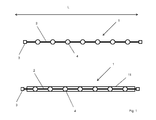
- FIG. 1 shows two embodiments of the inventive puncture and / or accident-securing means 1.
- Both embodiments of the puncture and / or accident-securing means 1 have a flexible support means 2, here a rope, preferably made of plastic, on.
- a connecting means 3 here hooks provided, which can be connected to a guardrail and / or its vertical support and a towing eye on a vehicle.
- a plurality of, here spherical, warning means 4 are arranged equidistantly.
- the length L of the puncture and / or accident-securing means is provided so that it corresponds to at least the width B of a stationary strip 6 of a roadway 5.
- the length L of the breakdown and / or accident-securing means according to the invention is at least twice the width B.
- the carrier means and / or the Warning means may be provided light-reflecting and / or fluorescent.
- the carrier means 2 and the warning means 4 are at least partially provided with a flexible envelope, which is optionally light-reflecting, self-luminous / flashing and / or fluorescent.
- this shock when passing over the warning means and / or the warning means burst when driving over, creating a noise that wakes the driver or caught his attention.
- the warning means are provided hollow.
- the puncture and / or accident-securing means is lighter and / or the noise when bursting larger.
- FIG. 2 shows by way of example possible cross-sectional shapes of the carrier. All profiles can be hollow. The expert understands that the cross section may also be pentagonal or> pentagonal. Further shows FIG. 2 in the lower part of an embodiment of the warning means 4. This is designed as a table tennis ball and materially connected to the support means 2. When driving over the warning device 4 bursts, causing a bang. Before bursting, the warning means 4 can still cause a shock in the overcoming motor vehicle.
- FIG. 3 shows the application of the breakdown and / or accident-securing means on the hard shoulder 6 a roadway 5, for example, a highway.
- the direction of travel of the motor vehicles is symbolized by the arrow 10.
- the driver drives on the hard shoulder 6 gets out, exceeds the guardrail 7 and goes with the breakdown and / or accident-securing means 1 on the side facing away from the guardrail far against the direction of travel 10 until he has a sufficient distance to his vehicle 8.
- he attaches the two connecting means 3, for example, to the vertical post of the guardrail and / or the guardrail itself and then throws or sets the support means 2 on the road so that it preferably completely covers the width B of the stationary strip 6.
- the support means 2 U- or V-shaped arranged on the hard shoulder.
- a driver driving a motor vehicle on the lane 5 falls asleep or careless and the vehicle thereby gets on the hard shoulder 6, his motor vehicle passes over the carrier means 2.
- the front and the rear wheels each receive two shocks, in the motor vehicle at least partially be initiated and registered by the driver, which wakes him up or attracts his attention. This gives him the opportunity to avoid an impact on the breakdown vehicle 8.
- the breakdown and / or accident-securing means can be dismantled and used as a tow rope. The driver of the breakdown vehicle does not need to enter the hard shoulder or the roadway for assembly or disassembly of the breakdown and / or accident-securing means.
- the embodiment according to FIG. 4 corresponds substantially to the embodiment according to FIG. 3 , except that in this case the support means 2 is arranged in an M-shape. This creates four impacts per wheel when driving over.
- the embodiment according to FIG. 5 corresponds substantially to the embodiment according to FIG. 3 , except that in this case the support means 2 is arranged W-shaped. This creates four impacts per wheel when driving over.
- the embodiment according to FIG. 6 corresponds substantially to the embodiment according to FIG. 3 , except that in this case the support means 2 is arranged in an N-shape. This creates three impacts per wheel when driving over.
- a person stands on at least one end of the puncture and / or accident safety device, this person preferably standing behind a crash barrier or a concrete deflector, and then throwing the carrier onto the roadway, that it is preferably one of the according to the Figures 3 - 6 takes the forms described.
Landscapes
- Engineering & Computer Science (AREA)
- Mechanical Engineering (AREA)
- Road Signs Or Road Markings (AREA)
Abstract
Description
- Die vorliegende Erfindung betrifft ein Pannen- und/oder Unfall-Sicherungsmittel mit einem flexiblen Trägermittel, an dem mindestens ein Verbindungsmittel vorgesehen ist und dessen Länge im Wesentlichen mindestens der Breite eines Standstreifens einer Fahrbahn entspricht, wobei der Querschnitt des Trägermittels so vorgesehen ist, dass beim Überfahren des Pannen- und/oder Unfall-Sicherungsmittels mit einem Kraftfahrzeug mindestens ein Stoß oder eine Vibration in diesem Kraftfahrzeug erzeugt wird und/oder dass an dem Trägermittel mindestens ein Warnmittel vorgesehen ist, das beim Überfahren des Pannen- und/oder Unfall-Sicherungsmittels mit einem Kraftfahrzeug mindestens einen Stoß oder eine Vibration in diesem Kraftfahrzeug und/oder ein akustisches Signal erzeugt. Des Weiteren betrifft die Erfindung ein Verfahren zur Absicherung einer Unfallstelle und/oder eines Unfall- und/oder Pannenfahrzeuges mit einem Pannen- und/oder Unfall-Sicherungsmittel.
- Der Sicherung von Unfallstellen oder Pannenfahrzeugen, die beispielsweise auf dem Standstreifen oder der linken Fahrbahn einer Autobahn abgestellt sind, gegen auffahrende Fahrzeuge kommt eine im größere Bedeutung zu. Für derartige Situationen haben viele Lastkraftwagen (LKW) mittlerweile mobile Schwellen an Bord, die, beispielsweise im Falle einer Panne, in einem hinreichenden Sicherheitsabstand hinter dem LKW, beispielsweise auf dem Standstreifen, platziert werden. Überfährt nun ein Kraftfahrzeug diese Schwellen, beispielsweise weil der Fahrer eingeschlafen ist, wird er beim Überfahren dieser Schwellen wieder geweckt und kann bremsen und/oder Lenken bevor das Kraftfahrzeug auf den LKW auffährt. So kann beispielsweise die Panne beseitigt werden, ohne dass Personen gefährdet werden. Für Personenkraftwagen (PKW) sind derartige Schwellen jedoch zu schwer und zu sperrig. Darüber hinaus haben Schwellen den Nachteil, dass eine Person den Standstreifen betreten muss, um die Schwellen auszulegen bzw. einzuladen.
- Es war deshalb die Aufgabe der vorliegenden Erfindung ein Pannen- und/oder Unfall-Sicherungsmittel zur Verfügung zu stellen, das die Nachteile des Standes der Technik nicht aufweist.
- Gelöst wird die Aufgabe mit einem Pannen- und/oder Unfall-Sicherungsmittel mit einem flexiblen Trägermittel, an dem mindestens ein Verbindungsmittel vorgesehen ist und dessen Länge im Wesentlichen mindestens der Breite eines Standstreifens einer Fahrbahn entspricht, wobei der Querschnitt des Trägermittels so vorgesehen ist, dass beim Überfahren des Pannen- und/oder Unfall-Sicherungsmittels mit einem Kraftfahrzeug mindestens ein Stoß oder eine Vibration in diesem Kraftfahrzeug erzeugt wird und/oder dass an dem Trägermittel mindestens ein Warnmittel vorgesehen ist, das beim Überfahren des Pannen- und/oder Unfall-Sicherungsmittels mit einem Kraftfahrzeug mindestens einen Stoß oder eine Vibration in diesem Kraftfahrzeug und/oder ein akustisches Signal erzeugt.
- Die vorliegende Erfindung betrifft ein Pannen- und/oder Unfall-Sicherungsmittel, mit dem ein Pannenfahrzeug oder eine Unfallstelle gegen auffahrende Kraftfahrzeuge gesichert werden kann. Das erfindungsgemäße Pannen- und/oder Unfall-Sicherungsmittel wird in einem hinreichenden Abstand, gebezogen auf die Fahrrichtung der Fahrbahn auf und/oder neben der das Fahrzeug steht oder auf der Unfall stattgefunden hat, hinter dem Pannenfahrzeug bzw. der Unfallstelle ausgelegt. Beim Überfahren der Pannen- und/oder Unfall-Sicherungsmittel wird der Fahrer des überfahrenden Kraftzeuges gewarnt und kann dann noch so reagieren, dass er nicht auf das Pannenfahrzeug auf- oder in die Unfallstelle hineinfährt. Das erfindungsgemäße Pannen- und/oder Unfall-Sicherungsmittel ist leicht in einem PKW zu verstauen und weist nur ein geringes Gewicht auf. In einer bevorzugten Ausführungsform kann das Pannen- und/oder Unfall-Sicherungsmittel auch als Abschleppmittel eingesetzt werden. Das erfindungsgemäße Pannen- und/oder Unfall-Sicherungsmittel kann auf einer Fahrbahn platziert werden, ohne dass diese betreten werden muss. Dadurch wird eine Gefährdung der auslegenden Person vermieden. Beispielsweise wird mindestens ein Ende, vorzugsweise beide Enden, des Pannen- und/oder Unfall-Sicherungsmittels an einer Leitplanke von einer Person festgemacht, die auf der der Fahrbahn abgewandten Seite der Leitplanke steht, und dann auf die Fahrbahn, insbesondere den Standstreifen oder die linke Fahrbahn einer Autobahn, gelegt und/oder geworfen. Dabei kann das Trägermittel so auf die Fahrbahn geworfen werden, dass es beispielsweis eine I-, Z-, U-, V- N-, W-oder M-Form einnimmt. Die fünf letztgenannten Formen haben den Vorteil, dass ein Rad des überfahrenden Kraftfahrzeuges das Trägermittel mehrfach überfährt, so dass mehrere, für den Fahrer wahrnehmbare Stöße entstehen.
- Gemäß einem anderen Beispiel stellt sich eine Person, die zwischen zwei Betonabweisern steht, auf mindestens ein, vorzugsweise beide Enden des Pannen- und/oder Unfall-Sicherungsmittels und legt und/oder wirft es dann auf die Fahrbahn, insbesondere die linke Fahrspur. Ansonsten wird auf das obige Beispiel verwiesen.
- Erfindungsgemäß weist das Pannen- und/oder Unfall-Sicherungsmittel ein flexibles Trägermittel auf, das sich im Wesentlichen über die gesamte Länge des Pannen- und/oder Unfall-Sicherungsmittels erstreckt. Flexibel im Sinne der Erfindung bedeutet, dass das Trägermittel reversibel beispielsweise zusammengerollt, zusammengeschoben und/oder zusammengefaltet werden kann und dass es auf der Fahrbahn die gewünschte Form einnimmt. Dadurch ist es möglich, dass das erfindungsgemäße Pannen- und/oder Unfall-Sicherungsmittel auf geringem Raum zu verstauen, es im Bedarfsfall aber in eine gewünschte, nahezu beliebig festlegbare Form zu bringen. Vorzugsweise handelt es sich bei dem Trägermittel um ein Seil, ein Band oder einen flexiblen Strang oder ein Kabel oder eine Litze oder einen Schlauch. Das Trägermittel kann ein- oder mehrstückig vorgesehen sein, wobei im letzteren Fall die Stücke fest oder beweglich miteinander verbunden sind. Das Trägermittel kann innen hohl sein. Das Trägermittel ist vorzugsweise aus einem Kunststoffmaterial gefertigt.
- Die Länge des gesamten Pannen- und/oder Unfall-Sicherungsmittels wird erfindungsgemäß so gewählt, dass es mindestens der Breite des Standstreifens einer Fahrbahn, insbesondere einer Autobahn, vorzugsweise einer Autobahn im Gebiet der Bundesrepublik Deutschland entspricht. Vorzugsweise ist das Pannen- und/oder Unfall-Sicherungsmittel jedoch länger, besonders bevorzugt 8 -12 m, ganz besonders bevorzugt 9 - 11 m.
- Erfindungsgemäß ist der Querschnitt des Trägermittels nun so gestaltet, dass beim Überfahren des Pannen- und/oder Unfall-Sicherungsmittels mit einem Kraftfahrzeug mindestens ein Stoß oder eine Vibration in diesem Kraftfahrzeug erzeugt wird. Diesen Stoß bzw. diese Vibration spürt der Fahrer des Fahrzeuges jeweils beim Überfahren des Pannen- und/oder Unfall-Sicherungsmittels mit dem Vorder- und dem Hinterrad. Dadurch wird Aufmerksamkeit geweckt. Der Querschnitt des Trägermittels kann eine beliebige Form aufweisen, solange der entsprechende Stoß bzw. die entsprechende Vibration erzeugt wird.
- Alternativ oder zusätzlich ist an oder in dem Trägermittel mindestens ein, vorzugsweise mehrere, Warnmittel vorgesehen, das jeweils beim Überfahren des Pannen- und/oder Unfall-Sicherungsmittels mit einem Kraftfahrzeug mindestens einen Stoß oder eine Vibration in diesem Kraftfahrzeug und/oder ein akustisches Signal erzeugt. Dieses akustische Signal, beispielsweise in Form eines Knalls, ist für den Fahrer des überfahrenden Kraftfahrzeuges und/oder für Personen, die sich im Bereich der Pannen- oder Unfallstelle befinden, wahrnehmbar, die dann entsprechend reagieren können. Vorzugsweise wird dieses Warnmittel beim Überfahren zumindest teilweise zerstört wodurch ein Geräusch, beispielsweise ein Knall oder ein Pfiff, entsteht. Alternativ oder zusätzlich entweicht beim Überfahren ein Medium aus dem Warnmittel, wodurch ein Geräusch, beispielsweise ein Pfiff entsteht. Vorzugsweise ist das Warnmittel innen hohl oder aus einem Vollmaterial gefertigt. Gemäß einer anderen bevorzugten Ausführungsform weist das Warnmittel eine innere Stützstruktur, beispielsweise Waben auf. Vorzugsweise ist der Abstand zwischen zwei Warnmitteln geringer als die minimale Breite eines für ein Kraftfahrzeug in Deutschland zugelassenen Reifens. Vorzugsweise sind die Warnmittel äquidistant entlang des Trägermittels angeordnet. Jedes Warnmittel ist vorzugsweise form- kraft- und/oder stoffschlüssig mit dem Trägermittel verbunden.
- Vorzugsweise weist das Pannen- und/oder Unfall-Sicherungsmittel zwei Verbindungsmittel auf, wobei ein Verbindungsmittel vorzugsweise an einem Ende des Trägermittels angeordnet ist. Das andere Verbindungsmittel kann an dem anderen Ende des Trägermittels befestigt sein. Dadurch können beide Enden beispielsweise mit einer Leitplanke am Straßenrand verbunden werden. Zusätzlich kann das Pannen- und/oder Unfall-Sicherungsmittel als Abschleppmittel eingesetzt werden. Es ist deshalb vorteilhaft, wenn das Verbindungsmittel mit einem Abschlepphaken eines Kraftfahrzeuges und mit einer Leitplanke verbindbar vorgesehen ist. Vorzugsweise sind jedoch alternativ oder zusätzlich ein oder mehrere Verbindungsstellen an dem Trägermittel für das zweite Verbindungsmittel abseits von den beiden Enden des Trägermittels vorgesehen. Beispielsweise kann bei einem 10 m langen Trägermittel eine Verbindungsstelle für das Verbindungsmittel 3,3 m entfernt von dem anderen Ende des Trägermittels vorgesehen sein, um beispielsweise das Pannen- und/oder Unfall-Sicherungsmittel in N-Form auslegen zu können. Die Verbindungsmittel können aus einem starren und/oder einem flexiblen Werkstoff gefertigt sein.
- Vorzugsweise ist das Pannen- und/oder Unfall-Sicherungsmittel auch ein Abschleppseil.
- Vorzugsweise ist das Pannen- und/oder Unfall-Sicherungsmittel zumindest teilweise lichtreflektierend, so dass es auch als optisches Warnmittel funktioniert. Vorzugsweise weist das Pannen- und/oder Unfall-Sicherungsmittel mindestens ein Leuchtmittel, beispielweise in Form von mindestens einer LED oder OLED auf. Dadurch kann die Unfall- oder Pannenstelle zusätzlich optisch, beispielweise durch leuchtendes und/oder blinkendes Licht, abgesichert werden. Besonders bevorzugt ist an oder in dem Trägermittel eine Energiequelle vorgesehen, mit der das Leuchtmittel betrieben wird.
- Ein weiterer Gegenstand der vorliegenden Erfindung ist ein Verfahren zur Absicherung einer Unfallstelle und/oder eines Unfall- und/oder Pannenfahrzeuges mit einem Pannen- und/oder Unfall-Sicherungsmittel, wobei das Pannen- und/oder Unfall-Sicherungsmittel, vorzugsweise an einer Leitplanke befestigt, und dann zumindest auf dem Standstreifen oder einer Fahrspur der Fahrbahn ausgebracht wird.
- Die zu dem erfindungsgemäßen Pannen- und/oder Unfall-Sicherungsmittel gemachten Ausführungen gelten für das erfindungsgemäße Verfahren gleichermaßen und umgekehrt.
- Bei dem erfindungsgemäßen Verfahren werden vorzugsweise beide Enden eines Pannen- und/oder Unfall-Sicherungsmittel mit der Leitplanke einer Fahrbahn verbunden und das Pannen- und/oder Unfall-Sicherungsmittel dann zumindest auf dem Standstreifen der Fahrbahn ausgebracht. Das erfindungsgemäße Verfahren hat den Vorteil, dass die gesamte Anbringung des Pannen- und/oder Unfall-Sicherungsmittels von einer Person vorgenommen werden kann, die sich auf der der Fahrbahn abgewandten Seite der Leitplanke befindet. Diese Person befestigt die Enden des Pannen- und/oder Unfall-Sicherungsmittels an der Leitplanke und wirft und/oder legt dann das Trägermittel des Pannen- und/oder Unfall-Sicherungsmittels auf die Fahrbahn, ohne diese jemals selbst zu betreten. Das Auswerfen/Auslegen kann sooft wiederholt werden, bis das Pannen- und/oder Unfall-Sicherungsmittel die gewünschte Form auf der Fahrbahn einnimmt. Auch für die Demontage des Pannen- und/oder Unfall-Sicherungsmittels muss die Fahrbahn nicht betreten werden.
- Vorzugsweise wird das Pannen- und/oder Unfall-Sicherungsmittel I-, U-, V oder M-förmig auf der Fahrbahn ausgelegt.
- Im Folgenden werden die Erfindungen anhand der
Figuren 1 - 6 erläutert. Diese Erläuterungen sind lediglich beispielhaft und schränken den allgemeinen Erfindungsgedanken nicht ein. Die Erläuterungen gelten für beide Gegenstände der vorliegenden Erfindung gleichermaßen. - Figur 1
- zeigt zwei Ausführungsformen des erfindungsgemäßen Pannen- und/oder Unfall-Sicherungsmittels.
- Figur 2
- zeigt mögliche Querschnittsformen des Trägermittels und eine Ausführungsform des Warnmittels.
- Figuren 3- 6
- zeigen Ausführungsformen der Ausbringung des Pannen- und/oder Unfall-Sicherungsmittels auf einem Standstreifen.
-
Figur 1 zeigt zwei Ausführungsformen des erfindungsgemäßen des Pannen- und/oder Unfall-Sicherungsmittels 1. Beide Ausführungsformen des Pannen- und/oder Unfall-Sicherungsmittels 1 weisen ein flexibles Trägermittel 2, hier ein Seil, das vorzugsweise aus Kunststoff, auf. An beiden Enden des Trägermittels 2 ist jeweils Verbindungsmittel 3, hier Haken, vorgesehen, die jeweils mit einer Leitplanke oder/oder deren vertikaler Stütze und mit einer Abschleppöse an einem Fahrzeug verbunden werden können. An dem Umfang des Trägermittels 2 sind eine Vielzahl von, hier kugelförmigen, Warnmitteln 4 äquidistant angeordnet. Die Länge L des Pannen- und/oder Unfall-Sicherungsmittels ist so vorgesehen, dass sie mindestens der Breite B eines Standstreifens 6 einer Fahrbahn 5 entspricht. Vorzugsweise beträgt die Länge L des erfindungsgemäßen Pannen- und/oder Unfall-Sicherungsmittels mindestens das Doppelte der Breite B. Das Trägermittel und/oder die Warnmittel können lichtreflektierend und/oder fluoreszierend vorgesehen sein. Bei der Ausführungsform gemäß der unteren Darstellung sind das Trägermittel 2 und die Warnmittel 4 zumindest abschnittsweise mit einer flexiblen Umhüllung versehen, die wahlweise lichtreflektierend, selbstleuchtend/blinkend und/oder fluoreszierend ist. Beim Überfahren des Pannen- und/oder Unfall-Sicherungsmittels mit einem Fahrzeug erfährt das überfahrende Kraftfahrzeug aufgrund des Querschnitts und des Materials des Trägermittels und/oder aufgrund des Querschnitts und/oder Materials des Warnmittels einen Stoß, den der Fahrer dieses überfahrenden Kraftfahrzeuges registriert und der seine Aufmerksamkeit weckt. Dadurch kann das Auffahren dieses Fahrzeug auf ein Unfall- oder Pannenfahrzeug verhindert werden. Alternativ oder zusätzlich entsteht dieser Stoß beim Überfahren der Warnmittel und/oder die Warnmittel platzen beim Überfahren, wodurch ein Geräusch entsteht, dass den Fahrer weckt oder dessen Aufmerksamkeit erregt. Vorzugsweise sind die Warnmittel hohl vorgesehen. Dadurch ist das Pannen- und/oder Unfall-Sicherungsmittel leichter und/oder die Geräuschentwicklung beim Platzen größer. -
Figur 2 zeigt beispielhaft mögliche Querschnittsformen des Trägermittels. Alle Profile können hohl sein. Der Fachmann versteht das der Querschnitt auch fünfeckig oder > fünfeckig sein kann. Des Weiteren zeigtFigur 2 im unteren Teil eine Ausführungsform des Warnmittels 4. Dieses ist wie ein Tischtennisball gestaltet und stoffschlüssig mit dem Trägermittel 2 verbunden. Beim Überfahren platzt das Warnmittel 4, wodurch ein Knall entsteht. Vor dem Platzen kann das Warnmittel 4 noch einen Stoß in dem überfahrenden Kraftfahrzeug bewirken. -
Figur 3 zeigt die Ausbringung des Pannen- und/oder Unfall-Sicherungsmittels auf dem Standstreifen 6 einer Fahrbahn 5, beispielsweise einer Autobahn. Die Fahrrichtung der Kraftfahrzeuge ist durch den Pfeil 10 symbolisiert. Im Fall einer Panne des Fahrzeuges 8, fährt der Fahrer auf den Standstreifen 6, steigt aus, übersteigt die Leitplanke 7 und geht mit dem Pannen- und/oder Unfall-Sicherungsmittel 1 auf der Fahrbahn abgewandten Seite der Leitplanke soweit entgegen der Fahrrichtung 10 bis er einen hinreichenden Abstand zu seinem Fahrzeug 8 hat. Dann befestigt er die beiden Verbindungsmittel 3 beispielsweise an dem vertikalen Pfosten der Leitplanke und/oder der Leitplanke selbst und wirft oder legt dann das Trägermittel 2 auf die Fahrbahn, so dass dieses die Breite B des Standstreifens 6 vorzugsweise vollständig überdeckt. In diesem Fall ist das Trägermittel 2 U- oder V-förmig auf dem Standstreifen angeordnet. Für den Fall, dass ein Fahrer, der ein Kraftfahrzeug auf der Fahrbahn 5 fährt, einschläft oder unachtsam wird und das Fahrzeug dadurch auf den Standstreifen 6 gerät, überfährt sein Kraftfahrzeug das Trägermittel 2. Dadurch erhalten die Vorder- und die Hinterräder jeweils zwei Stöße, die in das Kraftfahrzeug zumindest teilweise eingeleitet und von dem Fahrer registriert werden, wodurch er aufwacht oder seine Aufmerksamkeit erregt wird. Dadurch hat er Gelegenheit einen Aufprall auf das Pannenfahrzeug 8 zu vermeiden. Sobald Hilfe eingetroffen ist, kann das Pannen- und/oder Unfall-Sicherungsmittel demontiert und als Abschleppseil eingesetzt werden. Der Fahrer des Pannenfahrzeuges muss weder zur Montage noch zur Demontage des Pannen- und/oder Unfall-Sicherungsmittels den Standstreifen oder die Fahrbahn betreten. - Die Ausführungsform gemäß
Figur 4 entspricht im Wesentlichen der Ausführungsform gemäßFigur 3 , nur dass in diesem Fall das Trägermittel 2 M-förmig angeordnet ist. Dadurch entstehen beim Überfahren vier Stöße pro Rad. - Die Ausführungsform gemäß
Figur 5 entspricht im Wesentlichen der Ausführungsform gemäßFigur 3 , nur dass in diesem Fall das Trägermittel 2 W-förmig angeordnet ist. Dadurch entstehen beim Überfahren vier Stöße pro Rad. - Die Ausführungsform gemäß
Figur 6 entspricht im Wesentlichen der Ausführungsform gemäßFigur 3 , nur dass in diesem Fall das Trägermittel 2 N-förmig angeordnet ist. Dadurch entstehen beim Überfahren drei Stöße pro Rad. - Der Fachmann versteht, dass gemäß einer alternativen Ausführungsform, sich eine Person auf mindestens ein Ende des Pannen- und/oder Unfall-Sicherungsmittels stellt, wobei diese Person vorzugsweise hinter einer Leitplanke oder einem Betonabweiser steht, und dann das Trägermittel so auf die Fahrbahn wirft, dass es vorzugsweise eine der gemäß den
Figuren 3 - 6 beschriebenen Formen einnimmt. -
- 1
- Pannen- und/oder Unfall-Sicherungsmittel
- 2
- flexibles Trägermittel, flexibles Kunststoffteil und/oder flexibles Metallteil, Seil, Band, Schlauch
- 3
- Verbindungsmittel, Hacken, Schäkel
- 4
- akustisches-, vibratorisches- und/oder optisches Warnmittel
- 5
- Fahrbahn
- 6
- Standstreifen
- 7
- Leitplanke
- 8
- Pannen-/Unfallfahrzeug
- 9
- Person
- 10
- Fahrtrichtung
- 11
- Umhüllung
- L
- Länge des Pannen- und/oder Unfall-Sicherungsmittels
Claims (10)
- Pannen- und/oder Unfall-Sicherungsmittel (1) mit einem flexiblen Trägermittel (2), an dem mindestens ein Verbindungsmittel (3) vorgesehen ist und dessen Länge (L) im Wesentlichen mindestens der Breite (B) eines Standstreifens (6) einer Fahrbahn (5) entspricht, wobei der Querschnitt des Trägermittels (2) so vorgesehen ist, dass beim Überfahren des Pannen- und/oder Unfall-Sicherungsmittels (1) mit einem Kraftfahrzeug mindestens ein Stoß oder eine Vibration in diesem Kraftfahrzeug erzeugt wird und/oder dass an dem Trägermittel (2) mindestens ein Warnmittel (4) vorgesehen ist, das beim Überfahren des Pannen- und/oder Unfall-Sicherungsmittels (1) mit einem Kraftfahrzeug mindestens einen Stoß oder eine Vibration in diesem Kraftfahrzeug und/oder ein akustisches Signal erzeugt.
- Pannen- und/oder Unfall-Sicherungsmittel (1) nach Anspruch 1, dadurch gekennzeichnet, dass das Warnmittel (4) hohl ist, aus einem Vollmaterial gefertigt ist oder eine innere Stützstruktur aufweist.
- Pannen- und/oder Unfall-Sicherungsmittel (1) nach einem der Ansprüche 1 oder 2, dadurch gekennzeichnet, dass das Warnmittel (4) beim Überfahren mit einem Kraftfahrzeug zumindest platzt.
- Pannen- und/oder Unfall-Sicherungsmittel (1) nach einem der voranstehenden Ansprüche, dadurch gekennzeichnet, dass es an beiden Enden ein Verbindungsmittel aufweist.
- Pannen- und/oder Unfall-Sicherungsmittel (1) nach einem der voranstehenden Ansprüche, dadurch gekennzeichnet, dass das Verbindungsmittel mit einem Abschlepphaken und mit einer Leitplanke verbindbar vorgesehen ist.
- Pannen- und/oder Unfall-Sicherungsmittel (1) nach Anspruch 5, dadurch gekennzeichnet, dass es ein Abschleppseil ist.
- Pannen- und/oder Unfall-Sicherungsmittel (1) nach einem der voranstehenden Ansprüche, dadurch gekennzeichnet, dass es zumindest teilweise lichtreflektierend, selbstleuchtend oder blinkend ist.
- Verfahren zur Absicherung einer Unfallstelle und/oder eines Unfall- und/oder Pannenfahrzeuges mit einem Pannen- und/oder Unfall-Sicherungsmittel (1) insbesondere gemäß einem der voranstehenden Ansprüche, dadurch gekennzeichnet, dass Pannen- und/oder Unfall-Sicherungsmittel, vorzugsweise an einer Leitplanke befestigt wird, und dann zumindest auf einer Fahrbahn ausgebracht wird.
- Verfahren nach Anspruch 8, dadurch gekennzeichnet, dass beide Enden des Sicherungsmittels mit der Leitplanke verbunden werden.
- Verfahren nach einem der voranstehenden Ansprüche, dadurch gekennzeichnet, dass das Pannen- und/oder Unfall-Sicherungsmittel (1) U-, V oder M-förmig auf der Fahrbahn ausgebracht wird.
Applications Claiming Priority (1)
| Application Number | Priority Date | Filing Date | Title |
|---|---|---|---|
| DE102011113840A DE102011113840A1 (de) | 2011-09-21 | 2011-09-21 | Pannen- und/oder Unfall-Sicherungsmittel |
Publications (3)
| Publication Number | Publication Date |
|---|---|
| EP2572937A2 true EP2572937A2 (de) | 2013-03-27 |
| EP2572937A3 EP2572937A3 (de) | 2014-03-05 |
| EP2572937B1 EP2572937B1 (de) | 2017-11-08 |
Family
ID=46845642
Family Applications (1)
| Application Number | Title | Priority Date | Filing Date |
|---|---|---|---|
| EP12184906.1A Not-in-force EP2572937B1 (de) | 2011-09-21 | 2012-09-18 | Pannen- und/oder Unfall-Sicherungsmittel und Verfahren zur Absicherung einer Unfallstelle und/oder eines Unfall- und/oder Pannenfahrzeuges. |
Country Status (2)
| Country | Link |
|---|---|
| EP (1) | EP2572937B1 (de) |
| DE (1) | DE102011113840A1 (de) |
Cited By (1)
| Publication number | Priority date | Publication date | Assignee | Title |
|---|---|---|---|---|
| CN108914803A (zh) * | 2018-09-03 | 2018-11-30 | 侯万宁 | 一种公路划线反光材料 |
Family Cites Families (19)
| Publication number | Priority date | Publication date | Assignee | Title |
|---|---|---|---|---|
| DE856748C (de) * | 1951-05-20 | 1952-11-24 | Ind Chemicals Ltd | Strassenmarkierungsstreifen |
| DE1757663U (de) * | 1957-10-19 | 1957-12-12 | Prakla Gmbh | Schutzvorrichtung fuer provisorisch auf dem boden verlegte kabel u. dgl. |
| DE1954345U (de) * | 1963-04-03 | 1967-01-26 | Herbert Thalheim | Vorrichtung zur kenntlichmachung von haltenden fahrzeugen. |
| US3880537A (en) * | 1974-02-05 | 1975-04-29 | Hazard Warning Systems Limited | Road hazard warning device |
| DE7630478U1 (de) * | 1976-09-29 | 1977-03-03 | Widua Geb. Stritzke, Dagmar, 5030 Huerth | Markierungsband fuer fahrbahndecken |
| AT380041B (de) * | 1982-10-29 | 1986-03-25 | Semperit Ag | Verkehrsleitschwelle |
| DE3528044A1 (de) * | 1985-08-05 | 1987-02-26 | Karin Elke Hildmann | Reflektionskoerper |
| DE3533023A1 (de) * | 1985-09-16 | 1987-03-19 | Guido Alexander Kern | Vorrichtung zum kontrollierten abschleppen von kraftfahrzeugen |
| DE8807553U1 (de) * | 1988-06-10 | 1988-08-18 | Elastogran Kunststoff-Technik GmbH, 2844 Lemförde | Einrichtung für die Begrenzung, Markierung oder Absicherung von Fahrbahnen |
| DE9415432U1 (de) * | 1994-09-23 | 1995-01-26 | Siebertz, Dagmar, 63486 Bruchköbel | Gestaltung eines Sägezahnprofilkörpers mit definierten optischen und beim Befahren dieses Körpers, der automatischen Selbsterzeugung von zusätzlichen mechanischen und akustischen Signalen |
| DE29601324U1 (de) * | 1996-01-28 | 1996-10-17 | Nünning, Bernold, 49744 Geeste | Gummischacht |
| US6309137B1 (en) * | 1999-06-09 | 2001-10-30 | Robert Hirsch | Portable speed bump for traffic regulation |
| US20030132607A1 (en) * | 2002-01-11 | 2003-07-17 | Hsin-Yuan Pan | Safe automobile towing structure |
| DE202004019990U1 (de) * | 2004-12-21 | 2005-04-21 | Philippine Gmbh & Co. Technische Kunststoffe Kg | Vorrichtung zur Absicherung von Gefahrenstellen mit Warnschwellen |
| NL1031311C2 (nl) * | 2006-03-06 | 2007-09-07 | Nma Verkeerstechniek B V | Andreasmat en voertuig voorzien van een andreasmattenlegger. |
| DE102006025894A1 (de) * | 2006-06-02 | 2007-12-06 | Roswitha Rudzinski | Auffahr-Schutzmatte |
| US7731448B2 (en) * | 2007-04-11 | 2010-06-08 | Anthony Fillie | Portable rumble strip |
| US7736087B1 (en) * | 2008-12-22 | 2010-06-15 | Plastic Safety Systems, Inc. | Portable highway warning device |
| DE202010001775U1 (de) * | 2009-09-02 | 2010-05-06 | Schiessle, Rainer | Warnsicherheitsgummiband mit Reflektoren |
-
2011
- 2011-09-21 DE DE102011113840A patent/DE102011113840A1/de not_active Withdrawn
-
2012
- 2012-09-18 EP EP12184906.1A patent/EP2572937B1/de not_active Not-in-force
Non-Patent Citations (1)
| Title |
|---|
| None |
Cited By (1)
| Publication number | Priority date | Publication date | Assignee | Title |
|---|---|---|---|---|
| CN108914803A (zh) * | 2018-09-03 | 2018-11-30 | 侯万宁 | 一种公路划线反光材料 |
Also Published As
| Publication number | Publication date |
|---|---|
| DE102011113840A1 (de) | 2013-03-21 |
| EP2572937B1 (de) | 2017-11-08 |
| EP2572937A3 (de) | 2014-03-05 |
Similar Documents
| Publication | Publication Date | Title |
|---|---|---|
| DE112018000054T5 (de) | Katapultartiges sicherheitswarnschild für kraftfahrzeuge und katapultsystem davon | |
| EP1072476A2 (de) | Stossfängerabstützung für verbesserten Fussgängerschutz bei Kraftfahrzeugen | |
| EP2071082A2 (de) | Sperrkörper gegen Räder aufweisende Fahrzeuge | |
| DE102014018760B3 (de) | Fahrzeugkarosserie mit einem das Eindrehen eines Fahrzeugrades in Richtung der Fahrgastzelle verhindernden Zugelements bei einem teilüberdeckten Frontalaufprall | |
| EP2433870B1 (de) | Verfahren zum Betrieb eines Flughafenfahrzeuges | |
| DE202020103520U1 (de) | Anpralldämpfer und Schutzeinrichtung an Objekten | |
| DE102015016186A1 (de) | Kraftfahrzeugkarosserie mit zugstabiler Faserverstärkung | |
| EP2572937B1 (de) | Pannen- und/oder Unfall-Sicherungsmittel und Verfahren zur Absicherung einer Unfallstelle und/oder eines Unfall- und/oder Pannenfahrzeuges. | |
| DE1658664B2 (de) | Leitplanke fuer strassen | |
| DE202016104076U1 (de) | Sperrwerk zum Abfangen von Falschfahrern | |
| DE102014203512A1 (de) | Stoßfängereinheit für ein Kraftfahrzeug | |
| DE102014112000A1 (de) | Aufprallschutzelement für Baumstämme, Masten und dergleichen | |
| DE102010061380A1 (de) | Assistenzvorrichtung | |
| AT500180B1 (de) | Leitschiene | |
| EP1473207A1 (de) | Unfallschutzeinrichtung zum Anordnen zwischen zwei verkuppelten Fahrzeugen. | |
| AT501657B1 (de) | Sicherheitseinrichtung für verkehrswege | |
| DE102011012181B3 (de) | Warnvorrichtung für den Straßenverkehr | |
| DE10357157A1 (de) | Fahrzeug | |
| DE102014204271A1 (de) | Schienenfahrzeug mit einer Einrichtung zum Passantenschutz sowie Einrichtung zum Passantenschutz | |
| DE202009006623U1 (de) | Kollisionsabweisende Struktur für Kraftfahrzeuge | |
| DE102018118657A1 (de) | Intelligente Barrikade | |
| DE102019008254A1 (de) | Sicherheitsbarrierensystem, Sicherheitsbarrierensystemanordnung und ein damit ausgestattetes System | |
| DE10314021A1 (de) | Stoßfänger mit Einrollsicke | |
| EP2159327A2 (de) | Unterfahrschutz für eine Schutzplankenanordnung | |
| DE102017010178A1 (de) | Unterfahrschutz für einen Lastkraftwagen mit Leiterrahmen |
Legal Events
| Date | Code | Title | Description |
|---|---|---|---|
| PUAI | Public reference made under article 153(3) epc to a published international application that has entered the european phase |
Free format text: ORIGINAL CODE: 0009012 |
|
| AK | Designated contracting states |
Kind code of ref document: A2 Designated state(s): AL AT BE BG CH CY CZ DE DK EE ES FI FR GB GR HR HU IE IS IT LI LT LU LV MC MK MT NL NO PL PT RO RS SE SI SK SM TR |
|
| AX | Request for extension of the european patent |
Extension state: BA ME |
|
| PUAL | Search report despatched |
Free format text: ORIGINAL CODE: 0009013 |
|
| AK | Designated contracting states |
Kind code of ref document: A3 Designated state(s): AL AT BE BG CH CY CZ DE DK EE ES FI FR GB GR HR HU IE IS IT LI LT LU LV MC MK MT NL NO PL PT RO RS SE SI SK SM TR |
|
| AX | Request for extension of the european patent |
Extension state: BA ME |
|
| RIC1 | Information provided on ipc code assigned before grant |
Ipc: B60Q 7/00 20060101AFI20140129BHEP |
|
| 17P | Request for examination filed |
Effective date: 20140903 |
|
| RBV | Designated contracting states (corrected) |
Designated state(s): AL AT BE BG CH CY CZ DE DK EE ES FI FR GB GR HR HU IE IS IT LI LT LU LV MC MK MT NL NO PL PT RO RS SE SI SK SM TR |
|
| 17Q | First examination report despatched |
Effective date: 20160122 |
|
| GRAP | Despatch of communication of intention to grant a patent |
Free format text: ORIGINAL CODE: EPIDOSNIGR1 |
|
| INTG | Intention to grant announced |
Effective date: 20170516 |
|
| GRAS | Grant fee paid |
Free format text: ORIGINAL CODE: EPIDOSNIGR3 |
|
| GRAA | (expected) grant |
Free format text: ORIGINAL CODE: 0009210 |
|
| AK | Designated contracting states |
Kind code of ref document: B1 Designated state(s): AL AT BE BG CH CY CZ DE DK EE ES FI FR GB GR HR HU IE IS IT LI LT LU LV MC MK MT NL NO PL PT RO RS SE SI SK SM TR |
|
| REG | Reference to a national code |
Ref country code: GB Ref legal event code: FG4D Free format text: NOT ENGLISH |
|
| REG | Reference to a national code |
Ref country code: CH Ref legal event code: EP Ref country code: AT Ref legal event code: REF Ref document number: 943819 Country of ref document: AT Kind code of ref document: T Effective date: 20171115 |
|
| REG | Reference to a national code |
Ref country code: IE Ref legal event code: FG4D Free format text: LANGUAGE OF EP DOCUMENT: GERMAN |
|
| REG | Reference to a national code |
Ref country code: DE Ref legal event code: R096 Ref document number: 502012011606 Country of ref document: DE |
|
| REG | Reference to a national code |
Ref country code: NL Ref legal event code: MP Effective date: 20171108 |
|
| REG | Reference to a national code |
Ref country code: LT Ref legal event code: MG4D |
|
| PG25 | Lapsed in a contracting state [announced via postgrant information from national office to epo] |
Ref country code: FI Free format text: LAPSE BECAUSE OF FAILURE TO SUBMIT A TRANSLATION OF THE DESCRIPTION OR TO PAY THE FEE WITHIN THE PRESCRIBED TIME-LIMIT Effective date: 20171108 Ref country code: NO Free format text: LAPSE BECAUSE OF FAILURE TO SUBMIT A TRANSLATION OF THE DESCRIPTION OR TO PAY THE FEE WITHIN THE PRESCRIBED TIME-LIMIT Effective date: 20180208 Ref country code: NL Free format text: LAPSE BECAUSE OF FAILURE TO SUBMIT A TRANSLATION OF THE DESCRIPTION OR TO PAY THE FEE WITHIN THE PRESCRIBED TIME-LIMIT Effective date: 20171108 Ref country code: SE Free format text: LAPSE BECAUSE OF FAILURE TO SUBMIT A TRANSLATION OF THE DESCRIPTION OR TO PAY THE FEE WITHIN THE PRESCRIBED TIME-LIMIT Effective date: 20171108 Ref country code: LT Free format text: LAPSE BECAUSE OF FAILURE TO SUBMIT A TRANSLATION OF THE DESCRIPTION OR TO PAY THE FEE WITHIN THE PRESCRIBED TIME-LIMIT Effective date: 20171108 Ref country code: ES Free format text: LAPSE BECAUSE OF FAILURE TO SUBMIT A TRANSLATION OF THE DESCRIPTION OR TO PAY THE FEE WITHIN THE PRESCRIBED TIME-LIMIT Effective date: 20171108 |
|
| PG25 | Lapsed in a contracting state [announced via postgrant information from national office to epo] |
Ref country code: IS Free format text: LAPSE BECAUSE OF FAILURE TO SUBMIT A TRANSLATION OF THE DESCRIPTION OR TO PAY THE FEE WITHIN THE PRESCRIBED TIME-LIMIT Effective date: 20180308 Ref country code: LV Free format text: LAPSE BECAUSE OF FAILURE TO SUBMIT A TRANSLATION OF THE DESCRIPTION OR TO PAY THE FEE WITHIN THE PRESCRIBED TIME-LIMIT Effective date: 20171108 Ref country code: GR Free format text: LAPSE BECAUSE OF FAILURE TO SUBMIT A TRANSLATION OF THE DESCRIPTION OR TO PAY THE FEE WITHIN THE PRESCRIBED TIME-LIMIT Effective date: 20180209 Ref country code: RS Free format text: LAPSE BECAUSE OF FAILURE TO SUBMIT A TRANSLATION OF THE DESCRIPTION OR TO PAY THE FEE WITHIN THE PRESCRIBED TIME-LIMIT Effective date: 20171108 Ref country code: HR Free format text: LAPSE BECAUSE OF FAILURE TO SUBMIT A TRANSLATION OF THE DESCRIPTION OR TO PAY THE FEE WITHIN THE PRESCRIBED TIME-LIMIT Effective date: 20171108 Ref country code: BG Free format text: LAPSE BECAUSE OF FAILURE TO SUBMIT A TRANSLATION OF THE DESCRIPTION OR TO PAY THE FEE WITHIN THE PRESCRIBED TIME-LIMIT Effective date: 20180208 |
|
| PG25 | Lapsed in a contracting state [announced via postgrant information from national office to epo] |
Ref country code: CZ Free format text: LAPSE BECAUSE OF FAILURE TO SUBMIT A TRANSLATION OF THE DESCRIPTION OR TO PAY THE FEE WITHIN THE PRESCRIBED TIME-LIMIT Effective date: 20171108 Ref country code: SK Free format text: LAPSE BECAUSE OF FAILURE TO SUBMIT A TRANSLATION OF THE DESCRIPTION OR TO PAY THE FEE WITHIN THE PRESCRIBED TIME-LIMIT Effective date: 20171108 Ref country code: CY Free format text: LAPSE BECAUSE OF FAILURE TO SUBMIT A TRANSLATION OF THE DESCRIPTION OR TO PAY THE FEE WITHIN THE PRESCRIBED TIME-LIMIT Effective date: 20171108 Ref country code: DK Free format text: LAPSE BECAUSE OF FAILURE TO SUBMIT A TRANSLATION OF THE DESCRIPTION OR TO PAY THE FEE WITHIN THE PRESCRIBED TIME-LIMIT Effective date: 20171108 Ref country code: EE Free format text: LAPSE BECAUSE OF FAILURE TO SUBMIT A TRANSLATION OF THE DESCRIPTION OR TO PAY THE FEE WITHIN THE PRESCRIBED TIME-LIMIT Effective date: 20171108 |
|
| REG | Reference to a national code |
Ref country code: DE Ref legal event code: R097 Ref document number: 502012011606 Country of ref document: DE |
|
| PG25 | Lapsed in a contracting state [announced via postgrant information from national office to epo] |
Ref country code: IT Free format text: LAPSE BECAUSE OF FAILURE TO SUBMIT A TRANSLATION OF THE DESCRIPTION OR TO PAY THE FEE WITHIN THE PRESCRIBED TIME-LIMIT Effective date: 20171108 Ref country code: RO Free format text: LAPSE BECAUSE OF FAILURE TO SUBMIT A TRANSLATION OF THE DESCRIPTION OR TO PAY THE FEE WITHIN THE PRESCRIBED TIME-LIMIT Effective date: 20171108 Ref country code: PL Free format text: LAPSE BECAUSE OF FAILURE TO SUBMIT A TRANSLATION OF THE DESCRIPTION OR TO PAY THE FEE WITHIN THE PRESCRIBED TIME-LIMIT Effective date: 20171108 Ref country code: SM Free format text: LAPSE BECAUSE OF FAILURE TO SUBMIT A TRANSLATION OF THE DESCRIPTION OR TO PAY THE FEE WITHIN THE PRESCRIBED TIME-LIMIT Effective date: 20171108 |
|
| PLBE | No opposition filed within time limit |
Free format text: ORIGINAL CODE: 0009261 |
|
| STAA | Information on the status of an ep patent application or granted ep patent |
Free format text: STATUS: NO OPPOSITION FILED WITHIN TIME LIMIT |
|
| PG25 | Lapsed in a contracting state [announced via postgrant information from national office to epo] |
Ref country code: MT Free format text: LAPSE BECAUSE OF FAILURE TO SUBMIT A TRANSLATION OF THE DESCRIPTION OR TO PAY THE FEE WITHIN THE PRESCRIBED TIME-LIMIT Effective date: 20171108 |
|
| 26N | No opposition filed |
Effective date: 20180809 |
|
| REG | Reference to a national code |
Ref country code: FR Ref legal event code: PLFP Year of fee payment: 7 |
|
| PG25 | Lapsed in a contracting state [announced via postgrant information from national office to epo] |
Ref country code: SI Free format text: LAPSE BECAUSE OF FAILURE TO SUBMIT A TRANSLATION OF THE DESCRIPTION OR TO PAY THE FEE WITHIN THE PRESCRIBED TIME-LIMIT Effective date: 20171108 |
|
| PGFP | Annual fee paid to national office [announced via postgrant information from national office to epo] |
Ref country code: DE Payment date: 20181122 Year of fee payment: 7 Ref country code: AT Payment date: 20181019 Year of fee payment: 7 |
|
| PGFP | Annual fee paid to national office [announced via postgrant information from national office to epo] |
Ref country code: FR Payment date: 20181022 Year of fee payment: 7 Ref country code: GB Payment date: 20181025 Year of fee payment: 7 |
|
| PG25 | Lapsed in a contracting state [announced via postgrant information from national office to epo] |
Ref country code: MC Free format text: LAPSE BECAUSE OF FAILURE TO SUBMIT A TRANSLATION OF THE DESCRIPTION OR TO PAY THE FEE WITHIN THE PRESCRIBED TIME-LIMIT Effective date: 20171108 |
|
| REG | Reference to a national code |
Ref country code: CH Ref legal event code: PL |
|
| REG | Reference to a national code |
Ref country code: BE Ref legal event code: MM Effective date: 20180930 |
|
| REG | Reference to a national code |
Ref country code: IE Ref legal event code: MM4A |
|
| PG25 | Lapsed in a contracting state [announced via postgrant information from national office to epo] |
Ref country code: LU Free format text: LAPSE BECAUSE OF NON-PAYMENT OF DUE FEES Effective date: 20180918 |
|
| PG25 | Lapsed in a contracting state [announced via postgrant information from national office to epo] |
Ref country code: IE Free format text: LAPSE BECAUSE OF NON-PAYMENT OF DUE FEES Effective date: 20180918 |
|
| PG25 | Lapsed in a contracting state [announced via postgrant information from national office to epo] |
Ref country code: CH Free format text: LAPSE BECAUSE OF NON-PAYMENT OF DUE FEES Effective date: 20180930 Ref country code: BE Free format text: LAPSE BECAUSE OF NON-PAYMENT OF DUE FEES Effective date: 20180930 Ref country code: LI Free format text: LAPSE BECAUSE OF NON-PAYMENT OF DUE FEES Effective date: 20180930 |
|
| PG25 | Lapsed in a contracting state [announced via postgrant information from national office to epo] |
Ref country code: TR Free format text: LAPSE BECAUSE OF FAILURE TO SUBMIT A TRANSLATION OF THE DESCRIPTION OR TO PAY THE FEE WITHIN THE PRESCRIBED TIME-LIMIT Effective date: 20171108 |
|
| REG | Reference to a national code |
Ref country code: DE Ref legal event code: R119 Ref document number: 502012011606 Country of ref document: DE |
|
| PG25 | Lapsed in a contracting state [announced via postgrant information from national office to epo] |
Ref country code: HU Free format text: LAPSE BECAUSE OF FAILURE TO SUBMIT A TRANSLATION OF THE DESCRIPTION OR TO PAY THE FEE WITHIN THE PRESCRIBED TIME-LIMIT; INVALID AB INITIO Effective date: 20120918 Ref country code: PT Free format text: LAPSE BECAUSE OF FAILURE TO SUBMIT A TRANSLATION OF THE DESCRIPTION OR TO PAY THE FEE WITHIN THE PRESCRIBED TIME-LIMIT Effective date: 20171108 |
|
| PG25 | Lapsed in a contracting state [announced via postgrant information from national office to epo] |
Ref country code: MK Free format text: LAPSE BECAUSE OF NON-PAYMENT OF DUE FEES Effective date: 20171108 |
|
| PG25 | Lapsed in a contracting state [announced via postgrant information from national office to epo] |
Ref country code: AL Free format text: LAPSE BECAUSE OF FAILURE TO SUBMIT A TRANSLATION OF THE DESCRIPTION OR TO PAY THE FEE WITHIN THE PRESCRIBED TIME-LIMIT Effective date: 20171108 Ref country code: DE Free format text: LAPSE BECAUSE OF NON-PAYMENT OF DUE FEES Effective date: 20200401 |
|
| REG | Reference to a national code |
Ref country code: AT Ref legal event code: MM01 Ref document number: 943819 Country of ref document: AT Kind code of ref document: T Effective date: 20190918 |
|
| GBPC | Gb: european patent ceased through non-payment of renewal fee |
Effective date: 20190918 |
|
| PG25 | Lapsed in a contracting state [announced via postgrant information from national office to epo] |
Ref country code: FR Free format text: LAPSE BECAUSE OF NON-PAYMENT OF DUE FEES Effective date: 20190930 Ref country code: GB Free format text: LAPSE BECAUSE OF NON-PAYMENT OF DUE FEES Effective date: 20190918 |
|
| PG25 | Lapsed in a contracting state [announced via postgrant information from national office to epo] |
Ref country code: AT Free format text: LAPSE BECAUSE OF NON-PAYMENT OF DUE FEES Effective date: 20190918 |