EP2572760A2 - Manchette pare-feu - Google Patents
Manchette pare-feu Download PDFInfo
- Publication number
- EP2572760A2 EP2572760A2 EP12182952A EP12182952A EP2572760A2 EP 2572760 A2 EP2572760 A2 EP 2572760A2 EP 12182952 A EP12182952 A EP 12182952A EP 12182952 A EP12182952 A EP 12182952A EP 2572760 A2 EP2572760 A2 EP 2572760A2
- Authority
- EP
- European Patent Office
- Prior art keywords
- fire protection
- cutting
- strip
- protection collar
- longitudinal direction
- Prior art date
- Legal status (The legal status is an assumption and is not a legal conclusion. Google has not performed a legal analysis and makes no representation as to the accuracy of the status listed.)
- Withdrawn
Links
Images


Classifications
-
- F—MECHANICAL ENGINEERING; LIGHTING; HEATING; WEAPONS; BLASTING
- F16—ENGINEERING ELEMENTS AND UNITS; GENERAL MEASURES FOR PRODUCING AND MAINTAINING EFFECTIVE FUNCTIONING OF MACHINES OR INSTALLATIONS; THERMAL INSULATION IN GENERAL
- F16L—PIPES; JOINTS OR FITTINGS FOR PIPES; SUPPORTS FOR PIPES, CABLES OR PROTECTIVE TUBING; MEANS FOR THERMAL INSULATION IN GENERAL
- F16L5/00—Devices for use where pipes, cables or protective tubing pass through walls or partitions
- F16L5/02—Sealing
- F16L5/04—Sealing to form a firebreak device
-
- A—HUMAN NECESSITIES
- A62—LIFE-SAVING; FIRE-FIGHTING
- A62C—FIRE-FIGHTING
- A62C2/00—Fire prevention or containment
- A62C2/06—Physical fire-barriers
- A62C2/065—Physical fire-barriers having as the main closure device materials, whose characteristics undergo an irreversible change under high temperatures, e.g. intumescent
-
- F—MECHANICAL ENGINEERING; LIGHTING; HEATING; WEAPONS; BLASTING
- F16—ENGINEERING ELEMENTS AND UNITS; GENERAL MEASURES FOR PRODUCING AND MAINTAINING EFFECTIVE FUNCTIONING OF MACHINES OR INSTALLATIONS; THERMAL INSULATION IN GENERAL
- F16L—PIPES; JOINTS OR FITTINGS FOR PIPES; SUPPORTS FOR PIPES, CABLES OR PROTECTIVE TUBING; MEANS FOR THERMAL INSULATION IN GENERAL
- F16L57/00—Protection of pipes or objects of similar shape against external or internal damage or wear
- F16L57/04—Protection of pipes or objects of similar shape against external or internal damage or wear against fire or other external sources of extreme heat
-
- H—ELECTRICITY
- H02—GENERATION; CONVERSION OR DISTRIBUTION OF ELECTRIC POWER
- H02G—INSTALLATION OF ELECTRIC CABLES OR LINES, OR OF COMBINED OPTICAL AND ELECTRIC CABLES OR LINES
- H02G3/00—Installations of electric cables or lines or protective tubing therefor in or on buildings, equivalent structures or vehicles
- H02G3/02—Details
- H02G3/04—Protective tubing or conduits, e.g. cable ladders or cable troughs
- H02G3/0406—Details thereof
- H02G3/0412—Heat or fire protective means
-
- H—ELECTRICITY
- H02—GENERATION; CONVERSION OR DISTRIBUTION OF ELECTRIC POWER
- H02G—INSTALLATION OF ELECTRIC CABLES OR LINES, OR OF COMBINED OPTICAL AND ELECTRIC CABLES OR LINES
- H02G3/00—Installations of electric cables or lines or protective tubing therefor in or on buildings, equivalent structures or vehicles
- H02G3/22—Installations of cables or lines through walls, floors or ceilings, e.g. into buildings
Definitions
- the invention relates to a fire protection sleeve with a carrier strip consisting of sheet metal and an intumescent strip.
- Fire protection sleeves are arranged around pipes or cables which are guided through a breakthrough in a wall or ceiling and comprise intumescent material which expands when exposed to heat and closes the opening as tightly as possible, so that a spread of the fire can be prevented.
- FIG. 1 shown.
- a fire protection collar 2 is shown, which is fastened with holders 4 on a wall.
- the intumescent material contained in the fire protection sleeve 2 expands (as indicated by arrows) in the direction of the opening, through which a pipe 6 is guided.
- Fire protection sleeves with different diameters must be kept ready for fire protection of the breakthrough. This means a logistical and financial effort.
- EP 1 181 481 B1 is a continuous strip with transverse rupture lines known that used as a pipe size flexible fire sleeve can be.
- this strip is disadvantageous that the cutting must be done in at least two steps.
- Object of the present invention is to provide a fire sleeve, the size of which can be flexibly adjusted and which also can be easily processed.
- a fire protection collar which consists of a carrier strip consisting of sheet metal and an intumescent strip.
- the IntumeszenzstMail runs along the carrier tape and is connected to this.
- the carrier tape is provided with a plurality of predefined, in a longitudinal direction of the carrier tape spaced apart and extending transversely to the longitudinal direction cutting zones.
- the Intumeszenzstsammlung has a plurality of cutting areas, which are oriented in the same way as the cutting zones of the carrier tape. In the cutting regions, a thickness of the intumescent strip is reduced compared to the longitudinally adjacent regions. The cutting areas coincide with the cutting zones.
- the size of the fire sleeve according to aspects of the invention can be flexibly adjusted.
- the diameter of the band protection sleeve can be adapted to different diameters of breakthroughs while compact cuff outer dimensions can be maintained.
- the cutting of the sleeve can be done in a single step.
- a cutting tool such as a metal shears can be used.
- the carrier tape of the fire protection sleeve is designed so that this can be cut easily in the cutting zones.
- a thinner sheet may be used in the cutting zones than in the adjacent areas.
- the sheet may be perforated in the cutting zones.
- the width of the cutting zone or the cutting areas is chosen so that a cutting tool can pass unhindered into the cutting areas, without the to set adjacent thicker areas. Thus, as little as possible material must be cut, which means less effort when cutting the fire protection sleeve.
- the shearing areas should be at least as wide as the cutting tool (eg knife) or the part of the cutting tool which penetrates into the cutting zone (eg scissor legs). For most (simple) cutting tools, a width in the range of 2 to 6 mm has proven sufficient. However, it is possible to choose the width of the cutting zone outside this range.
- the intumescent strip viewed in the longitudinal direction of the carrier tape, has a rib or wave profile.
- the cutting areas of the intumescent strip are located in the troughs of this profile.
- the flanks of the wave crests which adjoin a cutting region and extend on both sides of the corresponding wave trough are preferably inclined in such a way that the cutting region located in the wave trough can be easily reached with a cutting tool.
- Another criterion for the choice of this opening angle is that in the event that the fire sleeve is wound around the smallest desired pipe diameter, the two edges of the wave crests do not touch or just so.
- the thickness of the intumescent strip in the cutting region is a maximum of 5 mm.
- This thickness is preferably designed so that the structural unit of carrier tape and Intumeszenzst Shape is sufficiently stable and does not break when wrapping a wiring harness.
- the thickness of the intumescent strip in the cutting area should be as thin as possible in order to ensure good cuttability of the fire protection collar. A maximum value of 5 mm has proven to be a good compromise in empirical tests.
- the width of the cutting area is at least 3 mm. This width should be chosen so large that a cutting tool can be used safely. Again, empirical studies have confirmed the stated value.
- the separation or cutting to length of the fire protection sleeve can be further simplified if, according to a further embodiment, the intumescent strip, viewed in the longitudinal direction of the carrier tape, consists of a plurality of separate blocks, between each of which there is a gap which forms a cutting region. Since the intumescent strip in this case is no longer consistent, the connection between the IntumeszenzstMail and the carrier tape can be improved by, according to a further aspect of the invention, the carrier tape is provided with a plurality of hooks. These can be formed by stamped and bent sheet metal sections of the carrier tape. Preferably, the sheet metal sections forming the hooks are provided with hooks at their side edges. Thus, the connection between carrier tape and IntumeszenzstMake can be further improved.
- the stamped sheet metal sections are arranged in groups.
- the resulting from the punching of the sheet metal sections openings may overlap with the cutting zones.
- the openings When viewed in the longitudinal direction of the carrier tape, the openings preferably also overlap one another.
- the openings may be pointed triangles, which are preferably arranged so that they point in the direction of the cutting zones.
- a fire protection sleeve according to one or more of the aforementioned aspects, on the one hand, enables an improved connection between the carrier tape and the intumescent strip and, on the other hand, realizes - with the same measures, i. Punching and bending the sheet metal sections - a targeted perforation in the cutting zone.
- the carrier tape can be easily cut through in the cutting zones.
- retaining tabs are provided at the edges of the carrier tape. These retaining tabs are spaced from each other in the longitudinal direction of the carrier tape and bent so that they rest against the narrow side surfaces of the IntumeszenzstMails. If an intumescent strip is used with a wave profile, then the retaining tabs, according to a further embodiment, are preferably applied to the end faces of the ribs of this wave profile.
- the intumescent strip is preferably poured onto the carrier band.
- This effective procedure will especially used in fire protection sleeves, the Intumeszenzstsammlung is consistent.
- the carrier tape and the IntumeszenzstMail are preferably pressed together.
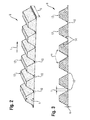
- FIG. 2 shows a schematic perspective view of a Intumeszenzstsammlungs 8 for a fire sleeve 2 according to a first embodiment.
- the intumescent strip 8 has cutting regions 10 which are located between the blocks 12 spaced apart in the longitudinal direction L.
- the thickness of the intumescent strip 8 is lower in these cutting regions 10 than in the adjacent regions which have a maximum thickness h.
- the thickness m of the Intumeszenzstsammlungs 8 in the cutting areas 10 is a maximum of 5 mm.
- the width t of the cutting regions 10 (see also FIG. 2 ) is at least 3 mm in the longitudinal direction L.
- the width b of the intumescent strip 8 is preferably between 20 and 100 mm, the maximum height h of the blocks 12 is preferably between 4 and 30 mm.
- FIG. 3 shows that off FIG. 2 known Intumeszenzst Shape 8 in a section.
- the minimum continuous strip thickness m is designed in such a way that the intumescent strip 8, together with a carrier strip, forms a sufficiently stable unit which does not break when wound around a wire strand.
- the thickness m is selected to be so thin that the intumescent strip 8 can be easily cut, for example with the help of a metal shears.
- the inclination of the flanks 14 is selected such that they include an opening angle ⁇ , which is so it is chosen that the flanks just do not touch after wrapping a pipe.
- the in the FIG. 2 and 3 shown intumescent strip 8 has a rib profile.
- the in the following FIG. 4 and 5 Intumescent strips 8 shown in cross section are provided with a wave profile ( FIG. 5 ) and a mixed wave / rib profile ( FIG. 4 ) Mistake.
- the flanks 14 of the blocks 12 are designed so that they include at least one opening angle ⁇ , which is also chosen so that the flanks just do not touch after wrapping a tube.
- ⁇ For the maximum thickness m of the intumescent strip 8 in the cutting regions 10, in turn, at least m ⁇ 5 mm applies.
- the width of the cutting regions 10 in the longitudinal direction L is at least 3 mm.
- intumescent strip 8 is preferably carried out in an extrusion process. It can be produced endlessly, whereby even in the soft state of the Intumeszenzstsammlungs 8 by a suitably shaped roller, the desired rib or wave structure can be rolled.
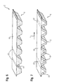
- FIG. 6 shows a fire sleeve 2 according to another embodiment.
- the intumescent strip 8 shown in the lower area is applied with its back to a carrier tape 16 made of sheet metal.
- the fire protection collar 2 is preferably produced by extruding the intumescent strip 8 directly onto the carrier tape 16 and then structuring it accordingly.
- the carrier tape 16 as in FIG. 7 shown, with spaced apart in the longitudinal direction L bent retaining tabs 18 be provided.
- the retaining tabs 18 of the carrier tape 16 are located on the end faces 20 of the blocks 12 of the Intumeszenzstsammlungs eighth
- the carrier tape 16 has cutting zones 22 which overlap with the cutting regions 10 of the intumescent strip 8.
- the cutting zones 22 and the cutting regions 10 are congruent.
- the cutting zones 22 may preferably be designed so that a severing of the fire protection collar 2 in the cutting zones 22 or the cutting regions 10 is facilitated.
- the carrier tape 16 may have a smaller thickness in the cutting zones 22, or e.g. be perforated by punching.
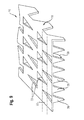
- FIG. 8th shows the punching image of a carrier tape 16, which has a plurality of Standzö réelleen 24 which have the shape of a sharp triangle.
- hooks 26 arise in the carrier tape 16 corresponding openings 25 remain, which also have the shape of a pointed triangle (see also FIG. 9 ).
- These openings 25 overlap with the cutting zones 22 of the carrier tape 16, whereby this targeted weakened in the cutting zones 22 and thus is better cut.
- the openings 25 formed by the punching out which have the shape of acute-angled triangles, are each oriented in the direction of the cutting zones 22. To this way, a targeted perforation of the carrier strip 16 in the region of the cutting zones 22 can be achieved.
- the openings 25, viewed in the longitudinal direction L overlap.
- FIG. 9 shows a simplified perspective view.
- the hooks 26 and the side flaps 18 project downwardly out of the plane of the carrier tape 16.
- the bending process is represented by corresponding arrows which illustrate a bending direction 28.
- the carrier tape 16 is weakened in the cutting zone 22 as a result of the punching and through the resulting openings 25 and thus easier to cut.
- To connect the Intumeszenzstsammlungs 8 with the carrier tape 16 of the IntumeszenzstMail 8 can be extruded onto the carrier tape 16.
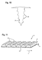
- a preferred alternative, however, is that first a trapezoidal strip of intumescent material is extruded and then adhered to an intumescent.
- FIG. 11 shows an example of such a structure in perspective view.
- the trapezoidal blocks 12 can be manufactured in an endless extrusion process and cut to the appropriate length (which corresponds to the width b of the intumescent strip 8). Subsequently, the individual blocks 12 can be adhesively bonded to an intumescent carrier 30, which can also be, for example, intumescent material, but also a tissue band.
- the intumescent strip 8 produced in this way is preferably provided with a carrier tape 16, as it is by way of example FIG. 9 shows, squeezed.
- the existing on the carrier tape 16 hook 26 can, as FIG. 10 shows barbs 32 may be provided.
- the blocks 12, different from that associated with FIG. 11 described method directly extruded or pressed onto a carrier tape 16.
- the intumescent strip 8 may preferably be produced from a casting resin. This can be poured or injected into a negative mold.
- the carrier tape 16 can be inserted into the still soft casting resin, the intumescent strip 8 formed in the cast resin mold and the carrier tape are joined during the curing process. After curing, the fire sleeve 2 is ready for use and can be cut to length according to the required size.
Landscapes
- Engineering & Computer Science (AREA)
- General Engineering & Computer Science (AREA)
- Mechanical Engineering (AREA)
- Emergency Management (AREA)
- Health & Medical Sciences (AREA)
- Public Health (AREA)
- Business, Economics & Management (AREA)
- Structural Engineering (AREA)
- Civil Engineering (AREA)
- Architecture (AREA)
- Clamps And Clips (AREA)
- Laminated Bodies (AREA)
- Details Of Indoor Wiring (AREA)
Applications Claiming Priority (1)
| Application Number | Priority Date | Filing Date | Title |
|---|---|---|---|
| DE102011083035 | 2011-09-20 |
Publications (2)
| Publication Number | Publication Date |
|---|---|
| EP2572760A2 true EP2572760A2 (fr) | 2013-03-27 |
| EP2572760A3 EP2572760A3 (fr) | 2015-08-26 |
Family
ID=46758662
Family Applications (1)
| Application Number | Title | Priority Date | Filing Date |
|---|---|---|---|
| EP12182952.7A Withdrawn EP2572760A3 (fr) | 2011-09-20 | 2012-09-04 | Manchette pare-feu |
Country Status (4)
| Country | Link |
|---|---|
| US (1) | US9140387B2 (fr) |
| EP (1) | EP2572760A3 (fr) |
| AU (1) | AU2012216613A1 (fr) |
| CA (1) | CA2786202C (fr) |
Cited By (11)
| Publication number | Priority date | Publication date | Assignee | Title |
|---|---|---|---|---|
| US9089726B1 (en) | 2014-05-16 | 2015-07-28 | Pyrophobic Systems, Ltd. | Passthrough firestops |
| EP3141786A1 (fr) * | 2015-09-10 | 2017-03-15 | HILTI Aktiengesellschaft | Passage de cable dote d'un stoppeur de fumee integre |
| EP3150893A1 (fr) * | 2015-09-29 | 2017-04-05 | HILTI Aktiengesellschaft | Passage de conduite destine a passer des conduites a travers un composant |
| US9797563B2 (en) | 2014-11-26 | 2017-10-24 | Ursatech Ltd. | Downlight firestop |
| US9803845B2 (en) | 2014-11-26 | 2017-10-31 | Ursatech Ltd. | Downlight firestop |
| EP3246613A1 (fr) * | 2016-05-19 | 2017-11-22 | HILTI Aktiengesellschaft | Panneau coupe-feu et caisson modulaire |
| US9853267B2 (en) | 2014-02-03 | 2017-12-26 | Ursatech Ltd. | Intumescent battery housing |
| EP3327327A1 (fr) * | 2016-11-24 | 2018-05-30 | HILTI Aktiengesellschaft | Dispositif coupe-feu intumescent, percé dans une paroi ou un plafond et procédé de fabrication de dispositifs coupe-feu intumescents |
| EP3477174A3 (fr) * | 2017-10-13 | 2019-08-07 | Rolf Kuhn GmbH | Manchette de protection contre l'incendie ainsi que logement correspondant et traversée de paroi ou de plafond comportant ladite manchette de protection contre l'incendie |
| US10704751B2 (en) | 2014-11-26 | 2020-07-07 | Ursatech Ltd. | Downlight firestop |
| US11794043B2 (en) | 2019-12-10 | 2023-10-24 | Ursatech Ltd. | Ceiling fixture firestop |
Families Citing this family (12)
| Publication number | Priority date | Publication date | Assignee | Title |
|---|---|---|---|---|
| EP2881638A1 (fr) | 2013-12-09 | 2015-06-10 | HILTI Aktiengesellschaft | Dispositif permettant de faire passer des conduites ou des câbles à travers une ouverture de bâtiment |
| EP3088784A1 (fr) * | 2015-04-27 | 2016-11-02 | Hilti Aktiengesellschaft | Manchette coupe-feu |
| EP3088783A1 (fr) | 2015-04-27 | 2016-11-02 | Hilti Aktiengesellschaft | Manchette coupe-feu |
| US10323856B2 (en) | 2015-05-22 | 2019-06-18 | Superposed Associates Llc | Passive ductwork intumescent fire damper |
| KR20170032727A (ko) * | 2015-09-15 | 2017-03-23 | 한국건설기술연구원 | 고온 파형단면 형상유지 구조를 이용한 화재보강구조 |
| EP3232105A1 (fr) * | 2016-04-12 | 2017-10-18 | HILTI Aktiengesellschaft | Procede de fabrication d'un module pour un passage de ligne, module et procede de fabrication d'un passage de ligne |
| US10363443B2 (en) | 2016-06-30 | 2019-07-30 | Superposed Associates Llc | Passive ductwork intumescent fire damper |
| WO2018178298A1 (fr) * | 2017-03-31 | 2018-10-04 | Promat Australia Pty. Ltd | Collier anti-incendie |
| WO2018178297A1 (fr) * | 2017-03-31 | 2018-10-04 | Promat Australia Pty. Ltd | Collier coupe-feu |
| ES2836445T3 (es) * | 2018-05-15 | 2021-06-25 | Oy Fcr Finland Ltd | Dispositivo de penetración |
| AU2021208639A1 (en) * | 2020-01-17 | 2022-08-18 | Simpson Strong-Tie Company Inc. | Fire stop installation at top plate of tie-down system |
| GB2595688B (en) * | 2020-06-03 | 2024-07-31 | Marley Ltd | Intumescent fire barrier |
Citations (1)
| Publication number | Priority date | Publication date | Assignee | Title |
|---|---|---|---|---|
| EP1181481B1 (fr) | 1999-05-07 | 2009-01-14 | Promat Australia Pty Ltd | Bande continue de matériau pour colliers coupe-feu |
Family Cites Families (10)
| Publication number | Priority date | Publication date | Assignee | Title |
|---|---|---|---|---|
| BE898845A (fr) * | 1984-02-06 | 1984-08-06 | Drim Ltd | Element en une composition refractaire intumescente et procede particulier de preparation de cette composition |
| DE4325757A1 (de) * | 1993-07-31 | 1995-02-02 | Gruenau Gmbh Chem Fab | Rohrschott mit einem um ein Rohr biegbaren Blechmantel |
| US6176052B1 (en) * | 1999-05-21 | 2001-01-23 | Tosetz Co., Ltd. | Fire retarding division penetrating member |
| DE10254086A1 (de) * | 2002-11-20 | 2004-06-03 | Hilti Ag | Abdichtsystem |
| DE102004007700A1 (de) | 2004-02-16 | 2005-09-01 | Cognis Deutschland Gmbh & Co. Kg | Rohrschott |
| US7596914B2 (en) * | 2005-12-15 | 2009-10-06 | Specified Technologies, Inc. | Universal firestopping collar assembly |
| US7712791B1 (en) * | 2007-01-05 | 2010-05-11 | Whitehead Anthony C | Caulking system |
| DE102008031018B4 (de) * | 2008-01-21 | 2019-03-28 | Doyma Gmbh & Co | Brandschutzmanschette |
| US8397452B2 (en) * | 2009-10-15 | 2013-03-19 | Specified Technologies Inc. | Firestopping bushing |
| NL2004318C2 (en) * | 2010-03-01 | 2011-09-05 | Walraven Holding Bv J Van | FIRESTOP COLLAR. |
-
2012
- 2012-08-13 CA CA2786202A patent/CA2786202C/fr active Active
- 2012-08-29 AU AU2012216613A patent/AU2012216613A1/en not_active Abandoned
- 2012-09-04 EP EP12182952.7A patent/EP2572760A3/fr not_active Withdrawn
- 2012-09-19 US US13/622,728 patent/US9140387B2/en active Active
Patent Citations (1)
| Publication number | Priority date | Publication date | Assignee | Title |
|---|---|---|---|---|
| EP1181481B1 (fr) | 1999-05-07 | 2009-01-14 | Promat Australia Pty Ltd | Bande continue de matériau pour colliers coupe-feu |
Cited By (18)
| Publication number | Priority date | Publication date | Assignee | Title |
|---|---|---|---|---|
| US9853267B2 (en) | 2014-02-03 | 2017-12-26 | Ursatech Ltd. | Intumescent battery housing |
| US10593921B2 (en) | 2014-02-03 | 2020-03-17 | Ursatech Ltd. | Intumescent battery housing |
| US9089726B1 (en) | 2014-05-16 | 2015-07-28 | Pyrophobic Systems, Ltd. | Passthrough firestops |
| US10551016B2 (en) | 2014-11-26 | 2020-02-04 | Ursatech Ltd. | Downlight firestop |
| US9803845B2 (en) | 2014-11-26 | 2017-10-31 | Ursatech Ltd. | Downlight firestop |
| US11408570B2 (en) | 2014-11-26 | 2022-08-09 | Ursatech Ltd. | Downlight firestop |
| US9797563B2 (en) | 2014-11-26 | 2017-10-24 | Ursatech Ltd. | Downlight firestop |
| US10704751B2 (en) | 2014-11-26 | 2020-07-07 | Ursatech Ltd. | Downlight firestop |
| WO2017042091A1 (fr) * | 2015-09-10 | 2017-03-16 | Hilti Aktiengesellschaft | Passage de câble muni d'un pare-fumée integré |
| AU2016320250B2 (en) * | 2015-09-10 | 2021-09-02 | Hilti Aktiengesellschaft | Line leadthrough with integrated smoke stopper |
| EP3141786A1 (fr) * | 2015-09-10 | 2017-03-15 | HILTI Aktiengesellschaft | Passage de cable dote d'un stoppeur de fumee integre |
| US10487964B2 (en) | 2015-09-10 | 2019-11-26 | Hilti Aktiengesellschaft | Line leadthrough with integrated smoke stopper |
| EP3150893A1 (fr) * | 2015-09-29 | 2017-04-05 | HILTI Aktiengesellschaft | Passage de conduite destine a passer des conduites a travers un composant |
| EP3246613A1 (fr) * | 2016-05-19 | 2017-11-22 | HILTI Aktiengesellschaft | Panneau coupe-feu et caisson modulaire |
| EP3327328A1 (fr) * | 2016-11-24 | 2018-05-30 | HILTI Aktiengesellschaft | Dispositif coupe-feu intumescent, percé dans une paroi ou un plafond et procédé de fabrication de dispositifs coupe-feu intumescents |
| EP3327327A1 (fr) * | 2016-11-24 | 2018-05-30 | HILTI Aktiengesellschaft | Dispositif coupe-feu intumescent, percé dans une paroi ou un plafond et procédé de fabrication de dispositifs coupe-feu intumescents |
| EP3477174A3 (fr) * | 2017-10-13 | 2019-08-07 | Rolf Kuhn GmbH | Manchette de protection contre l'incendie ainsi que logement correspondant et traversée de paroi ou de plafond comportant ladite manchette de protection contre l'incendie |
| US11794043B2 (en) | 2019-12-10 | 2023-10-24 | Ursatech Ltd. | Ceiling fixture firestop |
Also Published As
| Publication number | Publication date |
|---|---|
| US9140387B2 (en) | 2015-09-22 |
| EP2572760A3 (fr) | 2015-08-26 |
| AU2012216613A1 (en) | 2013-04-04 |
| US20140077043A1 (en) | 2014-03-20 |
| CA2786202C (fr) | 2019-06-11 |
| CA2786202A1 (fr) | 2013-03-20 |
Similar Documents
| Publication | Publication Date | Title |
|---|---|---|
| EP2572760A2 (fr) | Manchette pare-feu | |
| EP2682657A1 (fr) | Manchette pare-feu | |
| EP0429916B1 (fr) | Pièce de bourrage pour traversées de conducteurs | |
| DE102008034250A1 (de) | Verfahren zur Herstellung von Stahlfasern | |
| EP2144721B1 (fr) | Procédé de réalisation d'une bande de filons se composant d'une pluralité de filons parallèles entre eux, et bande de filons réalisée selon ce procédé | |
| DE2632828A1 (de) | Verfahren zum zusammenbauen von verformbaren elektrischen verbindern | |
| DE7232753U (de) | Kabelumschnürungsband | |
| DE102007028710B4 (de) | Herstellungsverfahren für Rohre, Walzenstraße zur Durchführung des Verfahrens, Flachrohr sowie Wärmetauscher mit derartigen Flachrohren | |
| EP2868827B1 (fr) | Rail profilé | |
| EP2227609B1 (fr) | Profilé métallique | |
| DE3047820C2 (de) | Verfahren zur Herstellung eines Sicherungselementes zum axialen Festlegen von Bolzen, Wellen oder dergleichen | |
| DE2622905A1 (de) | Rolladenstab und verfahren zu seiner herstellung | |
| DE102004005398A1 (de) | Verfahren zur Herstellung einer Spreizhülse und Spreizhülse | |
| EP1816373A2 (fr) | Chaîne porteuse pour lignes de transport d'énergie | |
| DE3011225C2 (de) | Fugenband sowie Verfahren und Vorrichtung zur Herstellung desselben | |
| EP2878414B1 (fr) | Outil de perforation | |
| DE10056442B4 (de) | Leitungskanal und Verfahren zu seiner Herstellung | |
| DE4137400C2 (de) | Preßkommutator und Verfahren zu seiner Herstellung | |
| DE69811772T2 (de) | Band für eine Befestigungsschelle und Befestigungsschelle | |
| EP3232105A1 (fr) | Procede de fabrication d'un module pour un passage de ligne, module et procede de fabrication d'un passage de ligne | |
| EP1464526A2 (fr) | Lame métallique d'insertion pour bandes d'enjolivement ou d'étanchéité | |
| DE102015103699A1 (de) | Montageeinheit mit eingestanztem Profilelement als Schweißelement zur Herstellung eines Hybridbauteils | |
| DE202014010822U1 (de) | "Gestanzter Metallträger für Dichtungen" | |
| DE1484092C (de) | Länglicher Hohlprofilkorper mit mehreren in Achsenlangsrichtung verlaufen den flachen Seitenflachen und Langskan ten sowie Verfahren zu seiner Herstellung | |
| DE20216945U1 (de) | Ankerleiste für die Bautechnik |
Legal Events
| Date | Code | Title | Description |
|---|---|---|---|
| PUAI | Public reference made under article 153(3) epc to a published international application that has entered the european phase |
Free format text: ORIGINAL CODE: 0009012 |
|
| AK | Designated contracting states |
Kind code of ref document: A2 Designated state(s): AL AT BE BG CH CY CZ DE DK EE ES FI FR GB GR HR HU IE IS IT LI LT LU LV MC MK MT NL NO PL PT RO RS SE SI SK SM TR |
|
| AX | Request for extension of the european patent |
Extension state: BA ME |
|
| PUAL | Search report despatched |
Free format text: ORIGINAL CODE: 0009013 |
|
| AK | Designated contracting states |
Kind code of ref document: A3 Designated state(s): AL AT BE BG CH CY CZ DE DK EE ES FI FR GB GR HR HU IE IS IT LI LT LU LV MC MK MT NL NO PL PT RO RS SE SI SK SM TR |
|
| AX | Request for extension of the european patent |
Extension state: BA ME |
|
| RIC1 | Information provided on ipc code assigned before grant |
Ipc: F16L 5/04 20060101ALI20150720BHEP Ipc: A62C 2/06 20060101AFI20150720BHEP |
|
| 17P | Request for examination filed |
Effective date: 20160226 |
|
| RBV | Designated contracting states (corrected) |
Designated state(s): AL AT BE BG CH CY CZ DE DK EE ES FI FR GB GR HR HU IE IS IT LI LT LU LV MC MK MT NL NO PL PT RO RS SE SI SK SM TR |
|
| 17Q | First examination report despatched |
Effective date: 20170706 |
|
| STAA | Information on the status of an ep patent application or granted ep patent |
Free format text: STATUS: THE APPLICATION IS DEEMED TO BE WITHDRAWN |
|
| 18D | Application deemed to be withdrawn |
Effective date: 20171219 |