EP2572760A2 - Flame retardant sleeve - Google Patents
Flame retardant sleeve Download PDFInfo
- Publication number
- EP2572760A2 EP2572760A2 EP12182952A EP12182952A EP2572760A2 EP 2572760 A2 EP2572760 A2 EP 2572760A2 EP 12182952 A EP12182952 A EP 12182952A EP 12182952 A EP12182952 A EP 12182952A EP 2572760 A2 EP2572760 A2 EP 2572760A2
- Authority
- EP
- European Patent Office
- Prior art keywords
- fire protection
- cutting
- strip
- protection collar
- longitudinal direction
- Prior art date
- Legal status (The legal status is an assumption and is not a legal conclusion. Google has not performed a legal analysis and makes no representation as to the accuracy of the status listed.)
- Withdrawn
Links
Images


Classifications
-
- F—MECHANICAL ENGINEERING; LIGHTING; HEATING; WEAPONS; BLASTING
- F16—ENGINEERING ELEMENTS AND UNITS; GENERAL MEASURES FOR PRODUCING AND MAINTAINING EFFECTIVE FUNCTIONING OF MACHINES OR INSTALLATIONS; THERMAL INSULATION IN GENERAL
- F16L—PIPES; JOINTS OR FITTINGS FOR PIPES; SUPPORTS FOR PIPES, CABLES OR PROTECTIVE TUBING; MEANS FOR THERMAL INSULATION IN GENERAL
- F16L5/00—Devices for use where pipes, cables or protective tubing pass through walls or partitions
- F16L5/02—Sealing
- F16L5/04—Sealing to form a firebreak device
-
- A—HUMAN NECESSITIES
- A62—LIFE-SAVING; FIRE-FIGHTING
- A62C—FIRE-FIGHTING
- A62C2/00—Fire prevention or containment
- A62C2/06—Physical fire-barriers
- A62C2/065—Physical fire-barriers having as the main closure device materials, whose characteristics undergo an irreversible change under high temperatures, e.g. intumescent
-
- F—MECHANICAL ENGINEERING; LIGHTING; HEATING; WEAPONS; BLASTING
- F16—ENGINEERING ELEMENTS AND UNITS; GENERAL MEASURES FOR PRODUCING AND MAINTAINING EFFECTIVE FUNCTIONING OF MACHINES OR INSTALLATIONS; THERMAL INSULATION IN GENERAL
- F16L—PIPES; JOINTS OR FITTINGS FOR PIPES; SUPPORTS FOR PIPES, CABLES OR PROTECTIVE TUBING; MEANS FOR THERMAL INSULATION IN GENERAL
- F16L57/00—Protection of pipes or objects of similar shape against external or internal damage or wear
- F16L57/04—Protection of pipes or objects of similar shape against external or internal damage or wear against fire or other external sources of extreme heat
-
- H—ELECTRICITY
- H02—GENERATION; CONVERSION OR DISTRIBUTION OF ELECTRIC POWER
- H02G—INSTALLATION OF ELECTRIC CABLES OR LINES, OR OF COMBINED OPTICAL AND ELECTRIC CABLES OR LINES
- H02G3/00—Installations of electric cables or lines or protective tubing therefor in or on buildings, equivalent structures or vehicles
- H02G3/02—Details
- H02G3/04—Protective tubing or conduits, e.g. cable ladders or cable troughs
- H02G3/0406—Details thereof
- H02G3/0412—Heat or fire protective means
-
- H—ELECTRICITY
- H02—GENERATION; CONVERSION OR DISTRIBUTION OF ELECTRIC POWER
- H02G—INSTALLATION OF ELECTRIC CABLES OR LINES, OR OF COMBINED OPTICAL AND ELECTRIC CABLES OR LINES
- H02G3/00—Installations of electric cables or lines or protective tubing therefor in or on buildings, equivalent structures or vehicles
- H02G3/22—Installations of cables or lines through walls, floors or ceilings, e.g. into buildings
Definitions
- the invention relates to a fire protection sleeve with a carrier strip consisting of sheet metal and an intumescent strip.
- Fire protection sleeves are arranged around pipes or cables which are guided through a breakthrough in a wall or ceiling and comprise intumescent material which expands when exposed to heat and closes the opening as tightly as possible, so that a spread of the fire can be prevented.
- FIG. 1 shown.
- a fire protection collar 2 is shown, which is fastened with holders 4 on a wall.
- the intumescent material contained in the fire protection sleeve 2 expands (as indicated by arrows) in the direction of the opening, through which a pipe 6 is guided.
- Fire protection sleeves with different diameters must be kept ready for fire protection of the breakthrough. This means a logistical and financial effort.
- EP 1 181 481 B1 is a continuous strip with transverse rupture lines known that used as a pipe size flexible fire sleeve can be.
- this strip is disadvantageous that the cutting must be done in at least two steps.
- Object of the present invention is to provide a fire sleeve, the size of which can be flexibly adjusted and which also can be easily processed.
- a fire protection collar which consists of a carrier strip consisting of sheet metal and an intumescent strip.
- the IntumeszenzstMail runs along the carrier tape and is connected to this.
- the carrier tape is provided with a plurality of predefined, in a longitudinal direction of the carrier tape spaced apart and extending transversely to the longitudinal direction cutting zones.
- the Intumeszenzstsammlung has a plurality of cutting areas, which are oriented in the same way as the cutting zones of the carrier tape. In the cutting regions, a thickness of the intumescent strip is reduced compared to the longitudinally adjacent regions. The cutting areas coincide with the cutting zones.
- the size of the fire sleeve according to aspects of the invention can be flexibly adjusted.
- the diameter of the band protection sleeve can be adapted to different diameters of breakthroughs while compact cuff outer dimensions can be maintained.
- the cutting of the sleeve can be done in a single step.
- a cutting tool such as a metal shears can be used.
- the carrier tape of the fire protection sleeve is designed so that this can be cut easily in the cutting zones.
- a thinner sheet may be used in the cutting zones than in the adjacent areas.
- the sheet may be perforated in the cutting zones.
- the width of the cutting zone or the cutting areas is chosen so that a cutting tool can pass unhindered into the cutting areas, without the to set adjacent thicker areas. Thus, as little as possible material must be cut, which means less effort when cutting the fire protection sleeve.
- the shearing areas should be at least as wide as the cutting tool (eg knife) or the part of the cutting tool which penetrates into the cutting zone (eg scissor legs). For most (simple) cutting tools, a width in the range of 2 to 6 mm has proven sufficient. However, it is possible to choose the width of the cutting zone outside this range.
- the intumescent strip viewed in the longitudinal direction of the carrier tape, has a rib or wave profile.
- the cutting areas of the intumescent strip are located in the troughs of this profile.
- the flanks of the wave crests which adjoin a cutting region and extend on both sides of the corresponding wave trough are preferably inclined in such a way that the cutting region located in the wave trough can be easily reached with a cutting tool.
- Another criterion for the choice of this opening angle is that in the event that the fire sleeve is wound around the smallest desired pipe diameter, the two edges of the wave crests do not touch or just so.
- the thickness of the intumescent strip in the cutting region is a maximum of 5 mm.
- This thickness is preferably designed so that the structural unit of carrier tape and Intumeszenzst Shape is sufficiently stable and does not break when wrapping a wiring harness.
- the thickness of the intumescent strip in the cutting area should be as thin as possible in order to ensure good cuttability of the fire protection collar. A maximum value of 5 mm has proven to be a good compromise in empirical tests.
- the width of the cutting area is at least 3 mm. This width should be chosen so large that a cutting tool can be used safely. Again, empirical studies have confirmed the stated value.
- the separation or cutting to length of the fire protection sleeve can be further simplified if, according to a further embodiment, the intumescent strip, viewed in the longitudinal direction of the carrier tape, consists of a plurality of separate blocks, between each of which there is a gap which forms a cutting region. Since the intumescent strip in this case is no longer consistent, the connection between the IntumeszenzstMail and the carrier tape can be improved by, according to a further aspect of the invention, the carrier tape is provided with a plurality of hooks. These can be formed by stamped and bent sheet metal sections of the carrier tape. Preferably, the sheet metal sections forming the hooks are provided with hooks at their side edges. Thus, the connection between carrier tape and IntumeszenzstMake can be further improved.
- the stamped sheet metal sections are arranged in groups.
- the resulting from the punching of the sheet metal sections openings may overlap with the cutting zones.
- the openings When viewed in the longitudinal direction of the carrier tape, the openings preferably also overlap one another.
- the openings may be pointed triangles, which are preferably arranged so that they point in the direction of the cutting zones.
- a fire protection sleeve according to one or more of the aforementioned aspects, on the one hand, enables an improved connection between the carrier tape and the intumescent strip and, on the other hand, realizes - with the same measures, i. Punching and bending the sheet metal sections - a targeted perforation in the cutting zone.
- the carrier tape can be easily cut through in the cutting zones.
- retaining tabs are provided at the edges of the carrier tape. These retaining tabs are spaced from each other in the longitudinal direction of the carrier tape and bent so that they rest against the narrow side surfaces of the IntumeszenzstMails. If an intumescent strip is used with a wave profile, then the retaining tabs, according to a further embodiment, are preferably applied to the end faces of the ribs of this wave profile.
- the intumescent strip is preferably poured onto the carrier band.
- This effective procedure will especially used in fire protection sleeves, the Intumeszenzstsammlung is consistent.
- the carrier tape and the IntumeszenzstMail are preferably pressed together.
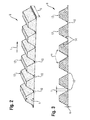
- FIG. 2 shows a schematic perspective view of a Intumeszenzstsammlungs 8 for a fire sleeve 2 according to a first embodiment.
- the intumescent strip 8 has cutting regions 10 which are located between the blocks 12 spaced apart in the longitudinal direction L.
- the thickness of the intumescent strip 8 is lower in these cutting regions 10 than in the adjacent regions which have a maximum thickness h.
- the thickness m of the Intumeszenzstsammlungs 8 in the cutting areas 10 is a maximum of 5 mm.
- the width t of the cutting regions 10 (see also FIG. 2 ) is at least 3 mm in the longitudinal direction L.
- the width b of the intumescent strip 8 is preferably between 20 and 100 mm, the maximum height h of the blocks 12 is preferably between 4 and 30 mm.
- FIG. 3 shows that off FIG. 2 known Intumeszenzst Shape 8 in a section.
- the minimum continuous strip thickness m is designed in such a way that the intumescent strip 8, together with a carrier strip, forms a sufficiently stable unit which does not break when wound around a wire strand.
- the thickness m is selected to be so thin that the intumescent strip 8 can be easily cut, for example with the help of a metal shears.
- the inclination of the flanks 14 is selected such that they include an opening angle ⁇ , which is so it is chosen that the flanks just do not touch after wrapping a pipe.
- the in the FIG. 2 and 3 shown intumescent strip 8 has a rib profile.
- the in the following FIG. 4 and 5 Intumescent strips 8 shown in cross section are provided with a wave profile ( FIG. 5 ) and a mixed wave / rib profile ( FIG. 4 ) Mistake.
- the flanks 14 of the blocks 12 are designed so that they include at least one opening angle ⁇ , which is also chosen so that the flanks just do not touch after wrapping a tube.
- ⁇ For the maximum thickness m of the intumescent strip 8 in the cutting regions 10, in turn, at least m ⁇ 5 mm applies.
- the width of the cutting regions 10 in the longitudinal direction L is at least 3 mm.
- intumescent strip 8 is preferably carried out in an extrusion process. It can be produced endlessly, whereby even in the soft state of the Intumeszenzstsammlungs 8 by a suitably shaped roller, the desired rib or wave structure can be rolled.
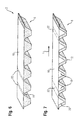
- FIG. 6 shows a fire sleeve 2 according to another embodiment.
- the intumescent strip 8 shown in the lower area is applied with its back to a carrier tape 16 made of sheet metal.
- the fire protection collar 2 is preferably produced by extruding the intumescent strip 8 directly onto the carrier tape 16 and then structuring it accordingly.
- the carrier tape 16 as in FIG. 7 shown, with spaced apart in the longitudinal direction L bent retaining tabs 18 be provided.
- the retaining tabs 18 of the carrier tape 16 are located on the end faces 20 of the blocks 12 of the Intumeszenzstsammlungs eighth
- the carrier tape 16 has cutting zones 22 which overlap with the cutting regions 10 of the intumescent strip 8.
- the cutting zones 22 and the cutting regions 10 are congruent.
- the cutting zones 22 may preferably be designed so that a severing of the fire protection collar 2 in the cutting zones 22 or the cutting regions 10 is facilitated.
- the carrier tape 16 may have a smaller thickness in the cutting zones 22, or e.g. be perforated by punching.
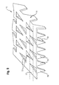
- FIG. 8th shows the punching image of a carrier tape 16, which has a plurality of Standzö réelleen 24 which have the shape of a sharp triangle.
- hooks 26 arise in the carrier tape 16 corresponding openings 25 remain, which also have the shape of a pointed triangle (see also FIG. 9 ).
- These openings 25 overlap with the cutting zones 22 of the carrier tape 16, whereby this targeted weakened in the cutting zones 22 and thus is better cut.
- the openings 25 formed by the punching out which have the shape of acute-angled triangles, are each oriented in the direction of the cutting zones 22. To this way, a targeted perforation of the carrier strip 16 in the region of the cutting zones 22 can be achieved.
- the openings 25, viewed in the longitudinal direction L overlap.
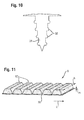
- FIG. 9 shows a simplified perspective view.
- the hooks 26 and the side flaps 18 project downwardly out of the plane of the carrier tape 16.
- the bending process is represented by corresponding arrows which illustrate a bending direction 28.
- the carrier tape 16 is weakened in the cutting zone 22 as a result of the punching and through the resulting openings 25 and thus easier to cut.
- To connect the Intumeszenzstsammlungs 8 with the carrier tape 16 of the IntumeszenzstMail 8 can be extruded onto the carrier tape 16.
- a preferred alternative, however, is that first a trapezoidal strip of intumescent material is extruded and then adhered to an intumescent.
- FIG. 11 shows an example of such a structure in perspective view.
- the trapezoidal blocks 12 can be manufactured in an endless extrusion process and cut to the appropriate length (which corresponds to the width b of the intumescent strip 8). Subsequently, the individual blocks 12 can be adhesively bonded to an intumescent carrier 30, which can also be, for example, intumescent material, but also a tissue band.
- the intumescent strip 8 produced in this way is preferably provided with a carrier tape 16, as it is by way of example FIG. 9 shows, squeezed.
- the existing on the carrier tape 16 hook 26 can, as FIG. 10 shows barbs 32 may be provided.
- the blocks 12, different from that associated with FIG. 11 described method directly extruded or pressed onto a carrier tape 16.
- the intumescent strip 8 may preferably be produced from a casting resin. This can be poured or injected into a negative mold.
- the carrier tape 16 can be inserted into the still soft casting resin, the intumescent strip 8 formed in the cast resin mold and the carrier tape are joined during the curing process. After curing, the fire sleeve 2 is ready for use and can be cut to length according to the required size.
Abstract
Description
Die Erfindung betrifft eine Brandschutzmanschette mit einem aus Blech bestehenden Trägerband und einem Intumeszenzstreifen.The invention relates to a fire protection sleeve with a carrier strip consisting of sheet metal and an intumescent strip.
Brandschutzmanschetten werden um Rohre oder Kabel, welche durch einen Durchbruch in einer Wand oder Decke geführt sind, angeordnet und umfassen Intumeszenzmaterial, welches sich bei Hitze ausdehnt und den Durchbruch möglichst dicht verschließt, sodass eine Ausbreitung des Feuers verhindert werden kann. Diese Situation ist beispielhaft in
In der
Aufgabe der vorliegenden Erfindung ist es, eine Brandschutzmanschette anzugeben, deren Größe flexibel angepasst werden kann und welche sich außerdem leicht verarbeiten lässt.Object of the present invention is to provide a fire sleeve, the size of which can be flexibly adjusted and which also can be easily processed.
Gemäß einem Aspekt der Erfindung wird eine Brandschutzmanschette angegeben, die aus einem aus Blech bestehenden Trägerband und einem Intumeszenzstreifen besteht. Der Intumeszenzstreifen verläuft entlang des Trägerbandes und ist mit diesem verbunden. Das Trägerband ist mit mehreren vordefinierten, in einer Längsrichtung des Trägerbandes voneinander beabstandeten und quer zu der Längsrichtung verlaufenden Schneidezonen versehen. Der Intumeszenzstreifen weist mehrere Schneidbereiche auf, welche in gleicher Weise wie die Schneidezonen des Trägerbandes orientiert sind. In den Schneidbereichen ist eine Dicke des Intumeszenzstreifens gegenüber den in Längsrichtung benachbarten Bereichen verringert. Die Schneidbereiche fallen mit den Schneidezonen zusammen.According to one aspect of the invention, a fire protection collar is specified which consists of a carrier strip consisting of sheet metal and an intumescent strip. The Intumeszenzstreifen runs along the carrier tape and is connected to this. The carrier tape is provided with a plurality of predefined, in a longitudinal direction of the carrier tape spaced apart and extending transversely to the longitudinal direction cutting zones. The Intumeszenzstreifen has a plurality of cutting areas, which are oriented in the same way as the cutting zones of the carrier tape. In the cutting regions, a thickness of the intumescent strip is reduced compared to the longitudinally adjacent regions. The cutting areas coincide with the cutting zones.
Die Größe der Brandschutzmanschette gemäß Aspekten der Erfindung kann flexibel angepasst werden. So kann der Durchmesser der Bandschutzmanschette an verschieden große Durchmesser von Durchbrüchen angepasst werden wobei gleichzeitig kompakte Manschettenaußenmaße eingehalten werden können. Vorteilhaft kann das Ablängen der Manschette in einem einzigen Arbeitsschritt erfolgen. Zur Ablängung der Brandschutzmanschette kann ein Schneidwerkzeug, beispielsweise eine Blechschere verwendet werden.The size of the fire sleeve according to aspects of the invention can be flexibly adjusted. Thus, the diameter of the band protection sleeve can be adapted to different diameters of breakthroughs while compact cuff outer dimensions can be maintained. Advantageously, the cutting of the sleeve can be done in a single step. To cut the fire protection sleeve, a cutting tool, such as a metal shears can be used.
Gemäß einem Aspekt der Erfindung ist das Trägerband der Brandschutzmanschette so gestaltet, dass sich dieses in den Schneidezonen leichter schneiden lässt. Zu diesem Zweck kann in den Schneidezonen ein dünneres Blech als in den benachbarten Bereichen verwendet werden. Auch kann das Blech in den Schneidezonen perforiert sein.According to one aspect of the invention, the carrier tape of the fire protection sleeve is designed so that this can be cut easily in the cutting zones. For this purpose, a thinner sheet may be used in the cutting zones than in the adjacent areas. Also, the sheet may be perforated in the cutting zones.
Die Breite der Schneidzone bzw. der Schneidbereiche ist so gewählt, dass ein Schneidwerkzeug ungehindert in die Schneidbereiche gelangen kann, ohne an die benachbarten dickeren Bereiche anzusetzen. Somit muss möglichst wenig Material durchtrennt werden, was einen geringeren Kraftaufwand beim Ablängen der Brandschutzmanschette bedeutet. Allgemein sollten die Scheidbereiche mindestens so breit wie das Schneidwerkzeug (z.B. Messer) bzw. der Teil des Schneidwerkzeugs, welcher in die Schneidzone dringt (z.B. Scherenschenkel), sein. Für die meisten (einfachen) Schneidwerkzeuge hat sich eine Breite im Bereich von 2 bis 6 mm als ausreichend herausgestellt. Es ist jedoch möglich, die Breite der Schneidzone außerhalb dieses Bereichs zu wählen.The width of the cutting zone or the cutting areas is chosen so that a cutting tool can pass unhindered into the cutting areas, without the to set adjacent thicker areas. Thus, as little as possible material must be cut, which means less effort when cutting the fire protection sleeve. In general, the shearing areas should be at least as wide as the cutting tool (eg knife) or the part of the cutting tool which penetrates into the cutting zone (eg scissor legs). For most (simple) cutting tools, a width in the range of 2 to 6 mm has proven sufficient. However, it is possible to choose the width of the cutting zone outside this range.
Gemäß einer Ausführungsform weist der Intumeszenzstreifen, in Längsrichtung des Trägerbandes betrachtet, ein Rippen- oder Wellenprofil auf. Die Schneidbereiche des Intumeszenzstreifens befinden sich in den Wellentälern dieses Profils. Die an einen Schneidebereich angrenzenden Flanken der Wellenberge, die sich zu beiden Seiten des entsprechenden Wellentals erstrecken, sind bevorzugt so geneigt, dass sich der im Wellental befindliche Schneidbereich mit einem Schneidwerkzeug bequem erreichen lässt.According to one embodiment, the intumescent strip, viewed in the longitudinal direction of the carrier tape, has a rib or wave profile. The cutting areas of the intumescent strip are located in the troughs of this profile. The flanks of the wave crests which adjoin a cutting region and extend on both sides of the corresponding wave trough are preferably inclined in such a way that the cutting region located in the wave trough can be easily reached with a cutting tool.
Ein weiteres Kriterium für die Wahl dieses Öffnungswinkels ist, dass in dem Fall, dass die Brandschutzmanschette um den kleinsten angestrebten Leitungsdurchmesser gewickelt ist, sich die beiden Flanken der Wellenberge nicht oder gerade so berühren.Another criterion for the choice of this opening angle is that in the event that the fire sleeve is wound around the smallest desired pipe diameter, the two edges of the wave crests do not touch or just so.
Gemäß einem weiteren Aspekt der Erfindung beträgt die Dicke des Intumeszenzstreifens in dem Schneidebereich maximal 5 mm. Diese Dicke ist bevorzugt so auszulegen, dass die strukturelle Einheit aus Trägerband und Intumeszenzstreifen ausreichend stabil ist und beim Umwickeln eines Leitungsstrangs nicht bricht. Die Dicke des Intumeszenzstreifens in dem Schneidbereich sollte andererseits so dünn wie möglich gewählt werden, damit eine gute Schneidbarkeit der Brandschutzmanschette gewährleistet ist. Ein Wert von maximal 5 mm hat sich in empirischen Versuchen als guter Kompromiss herausgestellt. Gemäß einer weiteren Ausführungsform beträgt die Breite des Schneidbereichs mindestens 3 mm. Diese Breite sollte so groß gewählt werden, dass ein Schneidwerkzeug sicher angesetzt werden kann. Auch hier haben empirische Untersuchungen den genannten Wert bestätigt.According to a further aspect of the invention, the thickness of the intumescent strip in the cutting region is a maximum of 5 mm. This thickness is preferably designed so that the structural unit of carrier tape and Intumeszenzstreifen is sufficiently stable and does not break when wrapping a wiring harness. On the other hand, the thickness of the intumescent strip in the cutting area should be as thin as possible in order to ensure good cuttability of the fire protection collar. A maximum value of 5 mm has proven to be a good compromise in empirical tests. According to a further embodiment, the width of the cutting area is at least 3 mm. This width should be chosen so large that a cutting tool can be used safely. Again, empirical studies have confirmed the stated value.
Das Abtrennen bzw. Ablängen der Brandschutzmanschette kann weiter vereinfacht werden, wenn, gemäß einer weiteren Ausführungsform, der Intumeszenzstreifen, in Längsrichtung des Trägerbandes betrachtet, aus mehreren getrennten Blöcken besteht, zwischen denen jeweils ein Zwischenraum vorhanden ist, der einen Schneidbereich bildet. Da der Intumeszenzstreifen in diesem Fall nicht mehr durchgängig ist, kann die Verbindung zwischen dem Intumeszenzstreifen und dem Trägerband verbessert werden, indem, gemäß einem weiteren Aspekt der Erfindung, das Trägerband mit mehreren Haken versehen wird. Diese können durch gestanzte und abgebogene Blechabschnitte des Trägerbandes gebildet sein. Bevorzugt sind die die Haken bildenden Blechabschnitte an ihren Seitenrändern mit Wiederhaken versehen. So kann die Verbindung zwischen Trägerband und Intumeszenzstreifen weiter verbessert werden.The separation or cutting to length of the fire protection sleeve can be further simplified if, according to a further embodiment, the intumescent strip, viewed in the longitudinal direction of the carrier tape, consists of a plurality of separate blocks, between each of which there is a gap which forms a cutting region. Since the intumescent strip in this case is no longer consistent, the connection between the Intumeszenzstreifen and the carrier tape can be improved by, according to a further aspect of the invention, the carrier tape is provided with a plurality of hooks. These can be formed by stamped and bent sheet metal sections of the carrier tape. Preferably, the sheet metal sections forming the hooks are provided with hooks at their side edges. Thus, the connection between carrier tape and Intumeszenzstreifen can be further improved.
Gemäß einem Aspekt der Erfindung sind die gestanzten Blechabschnitte in Gruppen angeordnet. Die durch das Stanzen der Blechabschnitte entstandenen Öffnungen können mit den Schneidzonen überlappen. In Längsrichtung des Trägerbandes betrachtet, überlappen bevorzugt auch die Öffnungen einander. Außerdem kann es sich bei den Öffnungen um spitze Dreiecke handeln, welche bevorzugt so angeordnet sind, dass sie in Richtung der Schneidzonen weisen. Eine Brandschutzmanschette gemäß einem oder mehrerer der vorgenannten Aspekte ermöglicht einerseits eine verbesserte Verbindung zwischen Trägerband und Intumeszenzstreifen und verwirklicht andererseits - mit den gleichen Maßnahmen, d.h. Ausstanzen und Umbiegen der Blechabschnitte - eine gezielte Perforation in der Schneidzone. So kann das Trägerband in den Schneidzonen leichter durchtrennt werden.According to one aspect of the invention, the stamped sheet metal sections are arranged in groups. The resulting from the punching of the sheet metal sections openings may overlap with the cutting zones. When viewed in the longitudinal direction of the carrier tape, the openings preferably also overlap one another. In addition, the openings may be pointed triangles, which are preferably arranged so that they point in the direction of the cutting zones. A fire protection sleeve according to one or more of the aforementioned aspects, on the one hand, enables an improved connection between the carrier tape and the intumescent strip and, on the other hand, realizes - with the same measures, i. Punching and bending the sheet metal sections - a targeted perforation in the cutting zone. Thus, the carrier tape can be easily cut through in the cutting zones.
Gemäß einer weiteren Ausführungsform sind Haltelaschen an den Rändern des Trägerbands vorgesehen. Diese Haltelaschen sind voneinander in Längsrichtung des Trägerbands beabstandet und derart gebogen, dass sie an den schmalen Seitenflächen des Intumeszenzstreifens anliegen. Wird ein Intumeszenzstreifen mit einem Wellenprofil verwendet, so liegen die Haltelaschen, gemäß einer weiteren Ausführungsform, bevorzugt an den Stirnseiten der Rippen dieses Wellenprofils an.According to a further embodiment, retaining tabs are provided at the edges of the carrier tape. These retaining tabs are spaced from each other in the longitudinal direction of the carrier tape and bent so that they rest against the narrow side surfaces of the Intumeszenzstreifens. If an intumescent strip is used with a wave profile, then the retaining tabs, according to a further embodiment, are preferably applied to the end faces of the ribs of this wave profile.
Bei der Herstellung einer Bandschutzmanschette wird der Intumeszenzstreifen bevorzugt auf das Trägerband aufgegossen. Dieses effektive Verfahren wird insbesondere bei Brandschutzmanschetten verwendet, deren Intumeszenzstreifen durchgängig ist. Bei Brandschutzmanschetten, die einen in Längsrichtung unterbrochenen und aus mehreren getrennten Blöcken bestehenden Intumeszenzstreifen aufweisen, werden das Trägerband und der Intumeszenzstreifen bevorzugt miteinander verpresst.When producing a band protection sleeve, the intumescent strip is preferably poured onto the carrier band. This effective procedure will especially used in fire protection sleeves, the Intumeszenzstreifen is consistent. In fire protection sleeves, which have a broken in the longitudinal direction and consisting of several separate blocks Intumeszenzstreifen, the carrier tape and the Intumeszenzstreifen are preferably pressed together.
Weitere Merkmale und Vorteile der Erfindung ergeben sich aus der folgenden Beschreibung vorteilhafter Ausführungsbeispiele unter Bezugnahme auf die beigefügten Zeichnungen. Dabei zeigt:
- FIG. 1
- eine Brandschutzmanschette in Draufsicht,
- FIG.2
- eine schematische Perspektivansicht eines Intumeszenzstreifens für eine Brandschutzmanschette gemäß einem Ausführungsbeispiel,
- FIG. 3
- diesen Intumeszenzstreifen in einer Schnittansicht,
- FIG. 4 und 5
- jeweils eine Schnittansicht eines Intumeszenzstreifens für Brandschutzmanschetten gemäß weiteren Ausführungsbeispielen,
- FIG. 6 und 7
- jeweils eine Brandschutzmanschette gemäß weiteren Ausführungsbeispielen,
- FIG. 8
- ein Stanzbild eines Trägerbandes für eine Brandschutzmanschette gemäß einem Ausführungsbeispiel,
- FIG. 9
- eine schematische Perspektivansicht dieses Trägerbandes in gebogenem Zustand,
- FIG. 10
- eine Detailansicht eines mit Wiederhaken versehenen Blechabschnitts eines solchen Trägerbandes, gemäß einem Ausführungsbeispiel und
- FIG. 11
- eine schematische Perspektivansicht einer Brandschutzmanschette gemäß einem weiteren Ausführungsbeispiel.
- FIG. 1
- a fire protection collar in plan view,
- FIG.2
- 1 is a schematic perspective view of an intumescent strip for a fire protection sleeve according to an embodiment,
- FIG. 3
- this intumescent strip in a sectional view,
- FIG. 4 and 5
- each a sectional view of a Intumeszenzstreifens for fire protection sleeves according to further embodiments,
- FIG. 6 and 7
- each a fire protection sleeve according to further embodiments,
- FIG. 8th
- a stamped image of a carrier tape for a fire protection sleeve according to an embodiment,
- FIG. 9
- a schematic perspective view of this carrier tape in the bent state,
- FIG. 10
- a detailed view of a provided with hook sheet metal portion of such a carrier tape, according to an embodiment and
- FIG. 11
- a schematic perspective view of a fire protection sleeve according to another embodiment.
Der in den
Die Herstellung der in den
Das Trägerband 16 weist Schneidezonen 22 auf, die mit den Schneidbereichen 10 des Intumeszenzstreifens 8 überlappen. Bevorzugt sind die Schneidezonen 22 und die Schneidbereiche 10 deckungsgleich. Die Schneidezonen 22 können bevorzugt so ausgelegt sein, dass ein Durchtrennen der Brandschutzmanschette 2 in den Schneidezonen 22 bzw. den Schneidbereichen 10 erleichtert ist. Beispielsweise kann das Trägerband 16 in den Schneidezonen 22 eine geringere Dicke aufweisen oder z.B. durch Ausstanzen perforiert sein.The
Das Ergebnis dieses Arbeitsschrittes zeigt
Gemäß einem weiteren Ausführungsbeispiel können die Blöcke 12, abweichend von dem im Zusammenhang mit
Wird der Intumeszenzstreifen 8, wie ihn
Der Intumeszenzstreifen 8 kann bevorzugt aus einem Gießharz hergestellt werden. Dieses kann in eine negative Form gegossen oder gespritzt werden. Das Trägerband 16 kann in das noch weiche Gießharz eingelegt werden, der in der Gießharzform entstehende Intumeszenzstreifen 8 und das Trägerband verbinden sich während des Aushärtevorgangs. Nach dem Aushärten ist die Brandschutzmanschette 2 einsatzbereit und kann entsprechend der benötigten Größe abgelängt werden.The
Claims (13)
Applications Claiming Priority (1)
| Application Number | Priority Date | Filing Date | Title |
|---|---|---|---|
| DE102011083035 | 2011-09-20 |
Publications (2)
| Publication Number | Publication Date |
|---|---|
| EP2572760A2 true EP2572760A2 (en) | 2013-03-27 |
| EP2572760A3 EP2572760A3 (en) | 2015-08-26 |
Family
ID=46758662
Family Applications (1)
| Application Number | Title | Priority Date | Filing Date |
|---|---|---|---|
| EP12182952.7A Withdrawn EP2572760A3 (en) | 2011-09-20 | 2012-09-04 | Flame retardant sleeve |
Country Status (4)
| Country | Link |
|---|---|
| US (1) | US9140387B2 (en) |
| EP (1) | EP2572760A3 (en) |
| AU (1) | AU2012216613A1 (en) |
| CA (1) | CA2786202C (en) |
Cited By (11)
| Publication number | Priority date | Publication date | Assignee | Title |
|---|---|---|---|---|
| US9089726B1 (en) | 2014-05-16 | 2015-07-28 | Pyrophobic Systems, Ltd. | Passthrough firestops |
| EP3141786A1 (en) * | 2015-09-10 | 2017-03-15 | HILTI Aktiengesellschaft | Circuit lead-through with integrated smoke stopper |
| EP3150893A1 (en) * | 2015-09-29 | 2017-04-05 | HILTI Aktiengesellschaft | Conduit feed-through for feeding conduits through a component |
| US9797563B2 (en) | 2014-11-26 | 2017-10-24 | Ursatech Ltd. | Downlight firestop |
| US9803845B2 (en) | 2014-11-26 | 2017-10-31 | Ursatech Ltd. | Downlight firestop |
| EP3246613A1 (en) * | 2016-05-19 | 2017-11-22 | HILTI Aktiengesellschaft | Fireproof panel and module box |
| US9853267B2 (en) | 2014-02-03 | 2017-12-26 | Ursatech Ltd. | Intumescent battery housing |
| EP3327327A1 (en) * | 2016-11-24 | 2018-05-30 | HILTI Aktiengesellschaft | Intumescence fire protection device, break in a wall or a ceiling and process for the preparation of intumescence fire protection devices |
| EP3477174A3 (en) * | 2017-10-13 | 2019-08-07 | Rolf Kuhn GmbH | Fire protection collar and housing therefor and wall or ceiling feedthrough having same |
| US10704751B2 (en) | 2014-11-26 | 2020-07-07 | Ursatech Ltd. | Downlight firestop |
| US11794043B2 (en) | 2019-12-10 | 2023-10-24 | Ursatech Ltd. | Ceiling fixture firestop |
Families Citing this family (12)
| Publication number | Priority date | Publication date | Assignee | Title |
|---|---|---|---|---|
| EP2881638A1 (en) | 2013-12-09 | 2015-06-10 | HILTI Aktiengesellschaft | Apparatus for guiding tubes or cables through a building opening |
| EP3088784A1 (en) * | 2015-04-27 | 2016-11-02 | Hilti Aktiengesellschaft | Flame retardant sleeve |
| EP3088783A1 (en) | 2015-04-27 | 2016-11-02 | Hilti Aktiengesellschaft | Flame retardant sleeve |
| US10323856B2 (en) | 2015-05-22 | 2019-06-18 | Superposed Associates Llc | Passive ductwork intumescent fire damper |
| KR20170032727A (en) * | 2015-09-15 | 2017-03-23 | 한국건설기술연구원 | A Fire Protection System Using Waved Profile of High Temperature Maintained Shape |
| EP3232105A1 (en) * | 2016-04-12 | 2017-10-18 | HILTI Aktiengesellschaft | Method for producing an assembly for a cable duct, assembly and method for manufacturing a cable duct |
| US10363443B2 (en) | 2016-06-30 | 2019-07-30 | Superposed Associates Llc | Passive ductwork intumescent fire damper |
| WO2018178298A1 (en) * | 2017-03-31 | 2018-10-04 | Promat Australia Pty. Ltd | Fire-protection collar |
| US11428347B2 (en) * | 2017-03-31 | 2022-08-30 | Promat Australia Pty Ltd | Fire-protection collar |
| ES2836445T3 (en) * | 2018-05-15 | 2021-06-25 | Oy Fcr Finland Ltd | Penetration device |
| WO2021146665A1 (en) * | 2020-01-17 | 2021-07-22 | Simpson Strong-Tie Company Inc. | Fire stop installation at top plate of tie-down system |
| GB2595688A (en) * | 2020-06-03 | 2021-12-08 | Marley Ltd | Intumescent fire barrier |
Citations (1)
| Publication number | Priority date | Publication date | Assignee | Title |
|---|---|---|---|---|
| EP1181481B1 (en) | 1999-05-07 | 2009-01-14 | Promat Australia Pty Ltd | Continuous strip of fire collar material |
Family Cites Families (10)
| Publication number | Priority date | Publication date | Assignee | Title |
|---|---|---|---|---|
| BE898845A (en) * | 1984-02-06 | 1984-08-06 | Drim Ltd | ELEMENT IN AN INTUMESCENT REFRACTORY COMPOSITION AND PARTICULAR PROCESS FOR PREPARING THE SAME |
| DE4325757A1 (en) | 1993-07-31 | 1995-02-02 | Gruenau Gmbh Chem Fab | Pipe bulkhead with a sheet metal jacket that can be bent around a pipe |
| US6176052B1 (en) * | 1999-05-21 | 2001-01-23 | Tosetz Co., Ltd. | Fire retarding division penetrating member |
| DE10254086A1 (en) * | 2002-11-20 | 2004-06-03 | Hilti Ag | sealing system |
| DE102004007700A1 (en) | 2004-02-16 | 2005-09-01 | Cognis Deutschland Gmbh & Co. Kg | Pipe bulkhead used for separating off combustible pipes and non-combustible pipes with combustible coverings and in assembly and installation |
| US7596914B2 (en) * | 2005-12-15 | 2009-10-06 | Specified Technologies, Inc. | Universal firestopping collar assembly |
| US7712791B1 (en) * | 2007-01-05 | 2010-05-11 | Whitehead Anthony C | Caulking system |
| DE102008031018B4 (en) * | 2008-01-21 | 2019-03-28 | Doyma Gmbh & Co | Fire protection sleeve |
| US8397452B2 (en) * | 2009-10-15 | 2013-03-19 | Specified Technologies Inc. | Firestopping bushing |
| NL2004318C2 (en) * | 2010-03-01 | 2011-09-05 | Walraven Holding Bv J Van | FIRESTOP COLLAR. |
-
2012
- 2012-08-13 CA CA2786202A patent/CA2786202C/en active Active
- 2012-08-29 AU AU2012216613A patent/AU2012216613A1/en not_active Abandoned
- 2012-09-04 EP EP12182952.7A patent/EP2572760A3/en not_active Withdrawn
- 2012-09-19 US US13/622,728 patent/US9140387B2/en active Active
Patent Citations (1)
| Publication number | Priority date | Publication date | Assignee | Title |
|---|---|---|---|---|
| EP1181481B1 (en) | 1999-05-07 | 2009-01-14 | Promat Australia Pty Ltd | Continuous strip of fire collar material |
Cited By (18)
| Publication number | Priority date | Publication date | Assignee | Title |
|---|---|---|---|---|
| US9853267B2 (en) | 2014-02-03 | 2017-12-26 | Ursatech Ltd. | Intumescent battery housing |
| US10593921B2 (en) | 2014-02-03 | 2020-03-17 | Ursatech Ltd. | Intumescent battery housing |
| US9089726B1 (en) | 2014-05-16 | 2015-07-28 | Pyrophobic Systems, Ltd. | Passthrough firestops |
| US10551016B2 (en) | 2014-11-26 | 2020-02-04 | Ursatech Ltd. | Downlight firestop |
| US9803845B2 (en) | 2014-11-26 | 2017-10-31 | Ursatech Ltd. | Downlight firestop |
| US11408570B2 (en) | 2014-11-26 | 2022-08-09 | Ursatech Ltd. | Downlight firestop |
| US9797563B2 (en) | 2014-11-26 | 2017-10-24 | Ursatech Ltd. | Downlight firestop |
| US10704751B2 (en) | 2014-11-26 | 2020-07-07 | Ursatech Ltd. | Downlight firestop |
| WO2017042091A1 (en) * | 2015-09-10 | 2017-03-16 | Hilti Aktiengesellschaft | Line leadthrough with integrated smoke stopper |
| AU2016320250B2 (en) * | 2015-09-10 | 2021-09-02 | Hilti Aktiengesellschaft | Line leadthrough with integrated smoke stopper |
| EP3141786A1 (en) * | 2015-09-10 | 2017-03-15 | HILTI Aktiengesellschaft | Circuit lead-through with integrated smoke stopper |
| US10487964B2 (en) | 2015-09-10 | 2019-11-26 | Hilti Aktiengesellschaft | Line leadthrough with integrated smoke stopper |
| EP3150893A1 (en) * | 2015-09-29 | 2017-04-05 | HILTI Aktiengesellschaft | Conduit feed-through for feeding conduits through a component |
| EP3246613A1 (en) * | 2016-05-19 | 2017-11-22 | HILTI Aktiengesellschaft | Fireproof panel and module box |
| EP3327328A1 (en) * | 2016-11-24 | 2018-05-30 | HILTI Aktiengesellschaft | Intumescence fire protection device, break in a wall or a ceiling and process for the preparation of intumescence fire protection devices |
| EP3327327A1 (en) * | 2016-11-24 | 2018-05-30 | HILTI Aktiengesellschaft | Intumescence fire protection device, break in a wall or a ceiling and process for the preparation of intumescence fire protection devices |
| EP3477174A3 (en) * | 2017-10-13 | 2019-08-07 | Rolf Kuhn GmbH | Fire protection collar and housing therefor and wall or ceiling feedthrough having same |
| US11794043B2 (en) | 2019-12-10 | 2023-10-24 | Ursatech Ltd. | Ceiling fixture firestop |
Also Published As
| Publication number | Publication date |
|---|---|
| CA2786202A1 (en) | 2013-03-20 |
| EP2572760A3 (en) | 2015-08-26 |
| US9140387B2 (en) | 2015-09-22 |
| AU2012216613A1 (en) | 2013-04-04 |
| US20140077043A1 (en) | 2014-03-20 |
| CA2786202C (en) | 2019-06-11 |
Similar Documents
| Publication | Publication Date | Title |
|---|---|---|
| EP2572760A2 (en) | Flame retardant sleeve | |
| EP2682657A1 (en) | Flame retardant sleeve | |
| EP0429916B1 (en) | Packing piece for conductor feed-throughs | |
| DE102008034250A1 (en) | Process for the production of steel fibers | |
| EP2144721B1 (en) | Method for the production of a wire strip comprising a plurality of wires arranged parallel to each other and wire strip produced according to said method | |
| DE2243610B2 (en) | Cable strapping tape | |
| DE2632828A1 (en) | METHOD OF ASSEMBLING DEFORMABLE ELECTRICAL CONNECTORS | |
| DE102007028710B4 (en) | Manufacturing process for pipes, rolling mill for carrying out the process, flat tube and heat exchangers with such flat tubes | |
| EP2868827B1 (en) | Profile rail | |
| EP2227609B1 (en) | Metal profile | |
| DE3047820C2 (en) | Process for the production of a securing element for axially fixing bolts, shafts or the like | |
| DE3405552A1 (en) | Plastic protective tube | |
| DE2919175C2 (en) | ||
| DE2622905A1 (en) | Composite roller shutter hooked slat - has metal part with plastic component joined together and extruded into metal | |
| DE102004005398A1 (en) | Method for producing an expansion sleeve and expansion sleeve | |
| EP1816373A2 (en) | Supporting chain for energy carriers | |
| DE3011225C2 (en) | Joint tape and method and device for producing the same | |
| EP2878414B1 (en) | Perforating tool | |
| EP1464526B1 (en) | Metallic insert band for trimming or sealing strips | |
| DE4137400C2 (en) | Press commutator and process for its manufacture | |
| DE69811772T2 (en) | Band for a fastening clamp and fastening clamp | |
| EP3232105A1 (en) | Method for producing an assembly for a cable duct, assembly and method for manufacturing a cable duct | |
| DE10056442B4 (en) | Conduit channel and process for its manufacture | |
| WO2015139996A1 (en) | Punched metal support for seals | |
| DE102015103699A1 (en) | Assembly unit with punched profile element as a welding element for producing a hybrid component |
Legal Events
| Date | Code | Title | Description |
|---|---|---|---|
| PUAI | Public reference made under article 153(3) epc to a published international application that has entered the european phase |
Free format text: ORIGINAL CODE: 0009012 |
|
| AK | Designated contracting states |
Kind code of ref document: A2 Designated state(s): AL AT BE BG CH CY CZ DE DK EE ES FI FR GB GR HR HU IE IS IT LI LT LU LV MC MK MT NL NO PL PT RO RS SE SI SK SM TR |
|
| AX | Request for extension of the european patent |
Extension state: BA ME |
|
| PUAL | Search report despatched |
Free format text: ORIGINAL CODE: 0009013 |
|
| AK | Designated contracting states |
Kind code of ref document: A3 Designated state(s): AL AT BE BG CH CY CZ DE DK EE ES FI FR GB GR HR HU IE IS IT LI LT LU LV MC MK MT NL NO PL PT RO RS SE SI SK SM TR |
|
| AX | Request for extension of the european patent |
Extension state: BA ME |
|
| RIC1 | Information provided on ipc code assigned before grant |
Ipc: F16L 5/04 20060101ALI20150720BHEP Ipc: A62C 2/06 20060101AFI20150720BHEP |
|
| 17P | Request for examination filed |
Effective date: 20160226 |
|
| RBV | Designated contracting states (corrected) |
Designated state(s): AL AT BE BG CH CY CZ DE DK EE ES FI FR GB GR HR HU IE IS IT LI LT LU LV MC MK MT NL NO PL PT RO RS SE SI SK SM TR |
|
| 17Q | First examination report despatched |
Effective date: 20170706 |
|
| STAA | Information on the status of an ep patent application or granted ep patent |
Free format text: STATUS: THE APPLICATION IS DEEMED TO BE WITHDRAWN |
|
| 18D | Application deemed to be withdrawn |
Effective date: 20171219 |