EP2572037B1 - Cutting and or creasing die and method of forming it - Google Patents
Cutting and or creasing die and method of forming it Download PDFInfo
- Publication number
- EP2572037B1 EP2572037B1 EP11783164.4A EP11783164A EP2572037B1 EP 2572037 B1 EP2572037 B1 EP 2572037B1 EP 11783164 A EP11783164 A EP 11783164A EP 2572037 B1 EP2572037 B1 EP 2572037B1
- Authority
- EP
- European Patent Office
- Prior art keywords
- rule
- die
- exemplary
- different
- rules
- Prior art date
- Legal status (The legal status is an assumption and is not a legal conclusion. Google has not performed a legal analysis and makes no representation as to the accuracy of the status listed.)
- Active
Links
- 0 *CC1CC(C*)CC1 Chemical compound *CC1CC(C*)CC1 0.000 description 1
Images


Classifications
-
- B—PERFORMING OPERATIONS; TRANSPORTING
- B31—MAKING ARTICLES OF PAPER, CARDBOARD OR MATERIAL WORKED IN A MANNER ANALOGOUS TO PAPER; WORKING PAPER, CARDBOARD OR MATERIAL WORKED IN A MANNER ANALOGOUS TO PAPER
- B31F—MECHANICAL WORKING OR DEFORMATION OF PAPER, CARDBOARD OR MATERIAL WORKED IN A MANNER ANALOGOUS TO PAPER
- B31F1/00—Mechanical deformation without removing material, e.g. in combination with laminating
- B31F1/07—Embossing, i.e. producing impressions formed by locally deep-drawing, e.g. using rolls provided with complementary profiles
-
- C—CHEMISTRY; METALLURGY
- C08—ORGANIC MACROMOLECULAR COMPOUNDS; THEIR PREPARATION OR CHEMICAL WORKING-UP; COMPOSITIONS BASED THEREON
- C08L—COMPOSITIONS OF MACROMOLECULAR COMPOUNDS
- C08L23/00—Compositions of homopolymers or copolymers of unsaturated aliphatic hydrocarbons having only one carbon-to-carbon double bond; Compositions of derivatives of such polymers
- C08L23/02—Compositions of homopolymers or copolymers of unsaturated aliphatic hydrocarbons having only one carbon-to-carbon double bond; Compositions of derivatives of such polymers not modified by chemical after-treatment
-
- B—PERFORMING OPERATIONS; TRANSPORTING
- B26—HAND CUTTING TOOLS; CUTTING; SEVERING
- B26F—PERFORATING; PUNCHING; CUTTING-OUT; STAMPING-OUT; SEVERING BY MEANS OTHER THAN CUTTING
- B26F1/00—Perforating; Punching; Cutting-out; Stamping-out; Apparatus therefor
- B26F1/38—Cutting-out; Stamping-out
- B26F1/44—Cutters therefor; Dies therefor
-
- B—PERFORMING OPERATIONS; TRANSPORTING
- B29—WORKING OF PLASTICS; WORKING OF SUBSTANCES IN A PLASTIC STATE IN GENERAL
- B29C—SHAPING OR JOINING OF PLASTICS; SHAPING OF MATERIAL IN A PLASTIC STATE, NOT OTHERWISE PROVIDED FOR; AFTER-TREATMENT OF THE SHAPED PRODUCTS, e.g. REPAIRING
- B29C48/00—Extrusion moulding, i.e. expressing the moulding material through a die or nozzle which imparts the desired form; Apparatus therefor
- B29C48/03—Extrusion moulding, i.e. expressing the moulding material through a die or nozzle which imparts the desired form; Apparatus therefor characterised by the shape of the extruded material at extrusion
- B29C48/05—Filamentary, e.g. strands
-
- B—PERFORMING OPERATIONS; TRANSPORTING
- B31—MAKING ARTICLES OF PAPER, CARDBOARD OR MATERIAL WORKED IN A MANNER ANALOGOUS TO PAPER; WORKING PAPER, CARDBOARD OR MATERIAL WORKED IN A MANNER ANALOGOUS TO PAPER
- B31F—MECHANICAL WORKING OR DEFORMATION OF PAPER, CARDBOARD OR MATERIAL WORKED IN A MANNER ANALOGOUS TO PAPER
- B31F1/00—Mechanical deformation without removing material, e.g. in combination with laminating
- B31F1/08—Creasing
- B31F1/10—Creasing by rotary tools
-
- C—CHEMISTRY; METALLURGY
- C08—ORGANIC MACROMOLECULAR COMPOUNDS; THEIR PREPARATION OR CHEMICAL WORKING-UP; COMPOSITIONS BASED THEREON
- C08L—COMPOSITIONS OF MACROMOLECULAR COMPOUNDS
- C08L77/00—Compositions of polyamides obtained by reactions forming a carboxylic amide link in the main chain; Compositions of derivatives of such polymers
-
- B—PERFORMING OPERATIONS; TRANSPORTING
- B26—HAND CUTTING TOOLS; CUTTING; SEVERING
- B26F—PERFORATING; PUNCHING; CUTTING-OUT; STAMPING-OUT; SEVERING BY MEANS OTHER THAN CUTTING
- B26F1/00—Perforating; Punching; Cutting-out; Stamping-out; Apparatus therefor
- B26F1/38—Cutting-out; Stamping-out
- B26F1/384—Cutting-out; Stamping-out using rotating drums
-
- B—PERFORMING OPERATIONS; TRANSPORTING
- B26—HAND CUTTING TOOLS; CUTTING; SEVERING
- B26F—PERFORATING; PUNCHING; CUTTING-OUT; STAMPING-OUT; SEVERING BY MEANS OTHER THAN CUTTING
- B26F1/00—Perforating; Punching; Cutting-out; Stamping-out; Apparatus therefor
- B26F1/38—Cutting-out; Stamping-out
- B26F1/44—Cutters therefor; Dies therefor
- B26F2001/4463—Methods and devices for rule setting, fixation, preparing cutting dies
-
- B—PERFORMING OPERATIONS; TRANSPORTING
- B31—MAKING ARTICLES OF PAPER, CARDBOARD OR MATERIAL WORKED IN A MANNER ANALOGOUS TO PAPER; WORKING PAPER, CARDBOARD OR MATERIAL WORKED IN A MANNER ANALOGOUS TO PAPER
- B31F—MECHANICAL WORKING OR DEFORMATION OF PAPER, CARDBOARD OR MATERIAL WORKED IN A MANNER ANALOGOUS TO PAPER
- B31F2201/00—Mechanical deformation of paper or cardboard without removing material
- B31F2201/07—Embossing
- B31F2201/0707—Embossing by tools working continuously
- B31F2201/0715—The tools being rollers
- B31F2201/0717—Methods and means for forming the embossments
-
- C—CHEMISTRY; METALLURGY
- C08—ORGANIC MACROMOLECULAR COMPOUNDS; THEIR PREPARATION OR CHEMICAL WORKING-UP; COMPOSITIONS BASED THEREON
- C08K—Use of inorganic or non-macromolecular organic substances as compounding ingredients
- C08K3/00—Use of inorganic substances as compounding ingredients
- C08K3/34—Silicon-containing compounds
- C08K3/36—Silica
-
- C—CHEMISTRY; METALLURGY
- C08—ORGANIC MACROMOLECULAR COMPOUNDS; THEIR PREPARATION OR CHEMICAL WORKING-UP; COMPOSITIONS BASED THEREON
- C08K—Use of inorganic or non-macromolecular organic substances as compounding ingredients
- C08K5/00—Use of organic ingredients
- C08K5/54—Silicon-containing compounds
- C08K5/541—Silicon-containing compounds containing oxygen
- C08K5/5425—Silicon-containing compounds containing oxygen containing at least one C=C bond
-
- C—CHEMISTRY; METALLURGY
- C08—ORGANIC MACROMOLECULAR COMPOUNDS; THEIR PREPARATION OR CHEMICAL WORKING-UP; COMPOSITIONS BASED THEREON
- C08L—COMPOSITIONS OF MACROMOLECULAR COMPOUNDS
- C08L23/00—Compositions of homopolymers or copolymers of unsaturated aliphatic hydrocarbons having only one carbon-to-carbon double bond; Compositions of derivatives of such polymers
- C08L23/02—Compositions of homopolymers or copolymers of unsaturated aliphatic hydrocarbons having only one carbon-to-carbon double bond; Compositions of derivatives of such polymers not modified by chemical after-treatment
- C08L23/16—Ethene-propene or ethene-propene-diene copolymers
-
- C—CHEMISTRY; METALLURGY
- C08—ORGANIC MACROMOLECULAR COMPOUNDS; THEIR PREPARATION OR CHEMICAL WORKING-UP; COMPOSITIONS BASED THEREON
- C08L—COMPOSITIONS OF MACROMOLECULAR COMPOUNDS
- C08L83/00—Compositions of macromolecular compounds obtained by reactions forming in the main chain of the macromolecule a linkage containing silicon with or without sulfur, nitrogen, oxygen or carbon only; Compositions of derivatives of such polymers
Definitions
- the present disclosure generally relates to die-cutting/creasing industry, and more particularly the disclosure relates to a system and method of manufacturing die-cutting/creasing and preparing pre-treated cardboards/papers.
- the package in which the goods are packed and presented may determine if the goods will be appealing to a potential buyer in the store.
- the packaging appearance can have a direct effect on the sales of merchandise.
- the terms package, paperboard box, parcel, box, carton box, cardboard box, brochure, flyers, etc. may be used interchangeably.
- Paper based material may be of different types, examples being waxed paper, cartridge paper, art paper, etc.
- the terms cardboard, card-stock, display board, corrugated fibre board, paperboards of different paper based material, folding boxboard, carton, blanks, and so on, may be used interchangeably.
- the present disclosure may use the term cardboard as a representative term for the above group.
- the pre-treatment of a cardboard may include the following acts: creating folding lines along the cardboard to ease and provide accurate folding of the cardboard; piercing the cardboard in different areas; creating embossment in different areas of the cardboard; cutting the raw cardboard into predefined shapes; and so on.
- the term pre-treated cardboard is used herein as representative of the above group.
- Some common techniques for preparing a pre-treated cardboard include the acts of placing the cardboard between dies, namely a rule die and a counter-die.
- the rule die may include a variety of different types of rules such as for cutting, creasing, embossing, scoring or a combination of the different types of dies.
- a steel-rule die body is usually a hard-wood based material AND is required to have a high-dimension stability and a high-grade and be without voids or other imperfections. Examples include plywood and maple wood, as well as plastic, metal, fabric, etc. Jammed deeply and firmly into a plurality of pre-made slots inside the die body is a plurality of steel-rules.
- the pre-made slots hold the steel-rules in place during the production of the steel-rule die. Further, the pre-made slots support the steel-rule during the operation of the cutting/creasing/embossing of numerous cardboards.
- the steel-rules are usually cut and bent blades made of hardened steel, for example. Usually, around the steel-rules, a plurality of ejection (rebound) rubbers need to be placed and glued. Without the ejection rubber the cardboard may tend to get stuck amongst the steel rules.
- Resilient creasing rings mounted on a die body are known from GB2429189 .
- the counter-die comprises a body, usually of a hard-wood-based material but alternatively of plastic, metal, fabric, etc. Commonly, a plurality of trenches is grooved in the counter-die. The location and structure of the trenches are required to fit precisely to the location and structure of the steel-rules of the steel-rule die.
- Steel rule dies have good durability and can withstand the harsh operating conditions, which can typically apply a 100 a few ton press force in a plurality of directions on the common rules.
- those skilled in the art will appreciate that the common steel-rule die and counter-die industry requires different craftsmen, long time leads for production, relies heavily on transportation, consumes tons of wood and/or tons of steel, demands huge storage areas, generates environmental pollution, and involves a complex cooperation between different companies, etc.
- the present disclosure provides a rule die comprising a die body having a broad surface; and a plurality of elongate rules protruding above said broad surface of said die body in order that, when a cardboard workpiece is subjected to compression between the die and a counter die, said rules impress or cut deform a surface of said workpiece facing the die to form elongate depressions therein, and characterised in that the rules are polymeric rules that are bonded to the broad surface and formed by extrusion and curing of a polymerisable material.
- a method of forming a rule die which comprises providing a die body having a broad surface, providing an extruder having a nozzle that is movable relative to the die body, extruding through the nozzle onto the broad surface of the die, as the nozzle and the die body are moved relative to one another, a flowable polymerisable material and polymerising the extruded material to form a rule that is bonded to the broad surface of the die body.
- the broad surface may either be smooth or it may be scraped, laser burned, etc.
- the rules may include a variety of different types of rules, and may include cutting, creasing, embossing rules; etc. Throughout the present disclosure, the term "rule” is use representative of all such types of rule.
- the rule die of the present disclosure can be manufactured by a single machine, and extrusion of the rules onto the broad surface of the die body may be automated and controlled by a computer, for example. Thus, no skilled craftsmen are required in the manufacturing of a die.
- the rule forming system alleviates the need for warehouse space because the layout and all information related to the rule die may be stored on a computer or other storing medium such as CDROM, flash disc, etc.
- the polymeric material of the rules may include one or more different types of polymers or even different combination of differing types of polymers.
- Exemplary polymers that may be used may include: polyester, polyamide, polycarbonate, polyurethane, acrylic, polypropylene, polyethylene, etc.
- the polymer may include one or more additives. These additives may include, but are not limited to: silica, ceramics, metal, various fibres, different fillers, etc.
- the rules may comprise several layers, or co-layers, which may be made of different materials. Each layer may also have a different shape, cross-section or width and may comprise different polymer types and/or additives; etc. Each layer may have a different required attribute. For example the lower layer may be required to have better adhesion attributes, the highest layer may be required to have better elasticity attributes, and so on.
- the surface adhered polymeric rules are capable of having a strong enough sustainability, firmness, inside-cohesion, robustness, and/or lifespan to withstand the pressure and harsh operation of high pressure press force (1 to 10 ton, for example) in one or more directions on the surface-adhesive rules during the cutting/creasing/embossing operation of the cardboards.
- the extruded polymerisable material (which may be a flowable liquid or gel-like material) should have the ability to preserve the required rule profile after it has been extruded through a nozzle onto the broad surface of the die body.
- the profile of the extruded die may differ by 10% to 30%, more preferably 5% to 15%, from the profile of the orifice of the nozzle through which the polymerisable material is extruded, and should retain this profile for a period from a few seconds to a few hours, preferably a few minutes.
- attributes of the flowable material include but are not limited to: thixotropic, pseudo plastic, hardness, high viscosity, etc.
- composition of ingredients may comprise: 7-50 percent additives such as, but not limited, to: silica, fillers, etc. In other exemplary embodiments the range of the additives may be 10-30 percent. Other exemplary embodiments of composition of ingredients may comprise 60-85 percent polymer. Exemplary polymers include but are not limited to : SPF 918, polyurethane, etc. In yet other embodiments a combination of the above may be used.
- exemplary attributes may include: flexibility, viscosity, cohesiveness, brittleness, tackiness, erectness, spreading capabilities, required thickness, etc.
- Drawing the die rule may comprise the following actions: create a rule; lay rule; and adhere the rule on the surface of the die body.
- the drawing of the rules may be done in a continuous motion, in a segmented motion, and/or a combination of both motions.
- the flowable material of the rules ingredients and the ratio between them may influence the different attributes of the flowable material.
- Exemplary ingredients may include: different polymers, silica, ceramics, fillers, fibre, etc.
- Exemplary ratios of combinations of different ingredients may be for UV curing (i.e., see tables 1 , and 2) and for thermal curing (i.e., see tables 3, 4 and 5): TABLE 1 Ingredient %Weight Exemplary Supplier SPF918 81.4 RAHN AEROSIL R-972 13.0 EVONIK Genocure LTM 2.8 RAHN Genocure LBC 2.8 RAHN TABLE 2 Ingredient %Weight Exemplary Supplier SPF918 80.9 RAHN AEROSIL R-812 13.5 EVONIK Genocure LTM 2.8 RAHN Genocure LBC 2.8 RAHN TABLE 3 Ingredient %Weight Exemplary Supplier U-1050 100 Polymer Gvulot EPC-238 34-45 Polymer Gvulot AEROSIL R-972 100 EVONIK TABLE 4 Ingredient %Weight Exemplary Supplier U-233 100 Polymer Gvulot EPC-238 34-45 Polymer Gvulot Cabosil M5 24 CABOT TABLE 5 Ingredient %Weight Exemplary Supplier
- the polymerisable material of the rule comprises one or more of a thermoplastic and a thermosetting material.
- materials include Polyurethane, having a hardness of 60 - 99 shore A, preferably, 80- 99 shore A or Polypropylene, etc.
- the viscosity of the material as deposited (drawn) may be between 1,000 cps and 145,000 cps, preferably between 17,000 cps and 80,000 cps, etc.
- the edges of the rule may be milled (scraped) in order to form a sharpened edge suitable for cutting.
- the milling may be done by mechanical or optical equipment.
- the rules may be have a hardness of 85 shore A and more or 35 shore D and more. Exemplary materials that may be used include polymers loaded with glass fibre, carbon fibre, Kevlar fibre or fillers like silica, metal, carbon black etc.
- the rule profiles may adopt different shapes. Examples of shapes that may be used in different embodiments may have a wide base, a non-symmetrical shape, a cone shape, a straight shape, and different combination of these.
- the shape and attributes of the rules may be determined according to different required parameters. These parameters may include, but are not limited to: the layout of the die; the distance between different rules; the direction from which harsh forces will strike the rules; the adhesive requirements; etc.
- the broad surface of the die to which the rules are adhered may be a flexible film.
- the flexible film may include one or more types of polymers. Exemplary polymers that may be used include, but are not limited to: polyester, polyamide, polycarbonate, and/or a combination of these polymers or others.
- the flexible film may include one or more additives. These additives may include, but not limited to: silica, ceramics, metal, different fillers, etc.
- Exemplary embodiments of the flexible film may comprise several layers (co-layers). Each layer may be constructed of a different material.
- the flexible film may be associated with, connected to, or joined with a substrate made from material other than flexible film.
- Materials such as, but not limited to, metal, wood, etc.
- the body of the die may be flat, cylindrical or of another shape.
- the body of the die may be flexible such that it can change its shape, for example from flat to cylindrical so it can be wrapped around a drum, for example.
- the flexible film of the die body may have a strong enough sustainability, firmness, inside-cohesion, robustness, and/or lifespan to withstand the pressures and harsh operation which can be around a few ton press force (1 to 10 ton, for example) in one or more directions during the cutting/creasing/embossing operation of the cardboards.
- a surface adhered polymeric rule permits use of a counter die constructed as a sheet that includes one or more types of polymers.
- Exemplary polymers that may be used include, but are not limited to: polyurethane, EPDM (ethylene propylene diene Monomer rubber), NBR (Nitrile butadiene rubber), acrylic rubber, silicone rubber, SBR (Styrene-Butadiene-Rubber) etc.
- the counter die sheet may include one or more additives. These additives may include, but not limited to: silica, ceramics metal, fillers, various fibres, slip agent, carbon black, talc, etc.
- the counter die film may comprise several layers. Each layer may be made of different materials.
- the counter die sheet may be associated with, joined to or connected to a support of different material. These materials may include, but not limited to metal, wood, PET (Polyethylene terephthalate) film, sponge material (with open or closed cells), etc.
- the counter die sheet may be associated with, joined to or connected to a sponge material, and the sponge material may be associated with, joined to or connected on its other side to a PET (Polyethylene terephthalate) base, and so on.
- the counter die's body may have a flat, cylindrical or any other shape.
- the counter die sheet and its base may be flexible such that it can change its shape, for example from flat to cylindrical so it can be wrapped around a drum, for example.
- the counter die sheet may have a strong enough sustainability, firmness, inside-cohesion, robustness, and/or lifespan to withstand pressure and harsh operation.
- the counter die may be supplied/sold as a die body, and/or as a die body associated with, joined to or connected to a drum or a flat base.
- the counter die body may be associated with a flat or drum base by moulding, coating, attachment by grippers, etc.
- the counter die sheet may have additional attributes.
- additional attributes may include, but are not limited to: flexibility, required thickness, resilience, required hardness, dimension stability, coefficient of friction, sustainability, inside-cohesion, robustness, life span, sponge attribute, wear-out resistance, etc.
- Exemplary counter dies may have a body that is comprised of a sheet made of polyurethane at a thickness of a few mm (1 .1 -3.7 mm, as a non-limiting example) with a shore hardness of a few tens (20-70 shore, as a non-limiting example).
- Exemplary embodiments of the counter die may comprise several layers. Each layer of the counter die sheet may be made from or comprise different ingredients. Further, each layer of the flexible-counter film may have different attributes. As a non-limiting example, the lowest or bottom layer may be comprised of a material with attributes that: have a high friction coefficient, are tacky, have an affinity, and/or include a degree of firmness. Further, the highest or top layer of the flexible-counter film may be comprised of a material with attributes that: have a high resilience, have a degree of flexibility, and/or are resistant to wearing out.
- An intermediate layer of the counter die sheet may be comprised of a material with attributes that provide sponginess or compression, etc.
- the flexible counter film may also be comprised of a lattice with a pre-defined density of one or more different fibres. Exemplary fibres in the lattice may include, but are not limited to, metal fibres, carbon fibres, etc.
- the flexible-counter film may be notched. The notches may be made in a variety of manners such as but not limited to by a laser.
- the constituents of the counter die sheet and their relative proportions may influence the different attributes of the flexible sheet.
- Exemplary ingredients may include, but are not limited to: different polymers, silica, ceramics, fillers, fibre etc.
- the surface of the counter die may be a blank surface, that is to say one devoid of trenches or pattern/layout.
- the surface of the counter die may be such that it adapts itself to the rule that it will encounter. This characteristic has the advantage of alleviating the need for resources and time that is required in the creation of trenches on a counter-die.
- the surface of the counter die body may return to a blank surface after the dies detach from each other (resilience attribute).
- the same counter die may be used for different rule dies. This characteristic that can be employed in various embodiments also results in reducing the cost and production time for the counter die.
- the counter die material may remember the pattern/ layout due to the press, this attribute may be achieved using thermoplastic material, for example.
- the surface of the counter die may include one or more trenches.
- the trenches may be created using a variety of different techniques. Exemplary techniques for creating the trenches may comprise: using a laser, drawing negative, extrusion, gnawing, moulding, coating, etc.
- the counter die may also be created using a variety of different techniques. Techniques for creating the counter die may include, but not limited to: moulding, coating, press/injection moulding, a combination of them, etc. More information on the different techniques of creating the counter die is disclosed below in conjunction with the description of figures 16 to 18.
- the rule die forming system proposed herein allows for new shapes of packages to be created and at a higher aesthetic quality. This also has been experimentally tested and verified by the applicants.
- the rule die forming system enables a user to create new and different shapes of creasing, cutting, and embossing and different alignment of the creasing, cutting and embossing on the cardboard.
- the rule die forming system enables: the pre-treated creasing to be much more refined; reduces ply-cracks and reduces the tearing of the cardboard; etc.
- a rule die and a counter die formed as flexible sheets may be relatively immune to changes in ambient parameters and over a wider range of ambient parameters.
- rule dies and counter dies provide consistent results when parameters such as, but not limited to, temperature, humidity, light, etc. vary or over a wide range.
- the rules may be bonded to the surface of a flexible surface-adhesive-rule die's body by adhesion.
- adhesion techniques may include, but are not limited to, using an intermediated-adhesive material between the rule and the broad surface of the die body.
- the intermediated adhesive material used may include, but is not limited to: Adcote 811 of DOW company, 238A + catalyst of MORCHEM company, etc.
- the bonding of the rules to the broad surface of the die body may be by virtue by adhesive properties of the rules and the broad surface of the die body. In further embodiments, the bonding is by virtue of a combination of these two method, or by other methods.
- Adhesive attributes may include, but are not limited to: epoxy, oligomer, silicone acrylate oligomer, adhesion promoter, photoinitiator.
- pre-treatment(s) may be done or applied before extrusion of the rules.
- pre-treatment examples include, but are not limited, different primers and primer techniques; Ozone-shower; high voltage electric cord; electron beam; plasma; flaming, etc.
- illuminating the body of the flexible rule die with UV light can be performed as a pre-treatment before laying and adhering the rules, for example.
- An adhesive material may be placed, spread, sprayed, coated, painted or otherwise placed onto the broad surface of the die body either prior to or at the same time as the extrusion of the rules.
- the adhesive material may be by means of a head associated with or controlled by a leading mechanism.
- An extrusion head may operate to automatically extrude rules onto the broad surface of rule die at the desired locations.
- the extrusion of the rules may be performed in a continuous motion, in a segmented motion, and/or a combination of both motions as well as a variety of other techniques.
- An extrusion head may suitably comprise an extrusion nozzle, a controller, and a leading mechanism.
- the leading mechanism under the control of the controller, may operate to move the extrusion nozzle to different locations and in different directions.
- the leading mechanism may be a mechanical arm, one or more rails, etc.
- the controller may control the extrusion nozzle as well as the leading mechanism. For instance, the controller may operate to cause the leading mechanism to move the drawing head to a desired location, then trigger the extrusion nozzle to commenced the drawing of a rule.
- the controller may form part of a computer programmed by means of software, firmware etc.
- Software may be embodied on a computer readable medium such as a read/write hard disc, CDROM, Flash memory, ROM, or other memory or storage, etc.
- a software program may be loaded to an appropriate processor or operated by a computer.
- the controller being integral to a computer, the computer may be loaded with a job description.
- the job description may include: the type of the rules, the type and thickness of the cardboard, the layout of the surface-adhesive-rule die, etc.
- the layout of the rule die may include, the placement of each rule and its type. According to the layout of the rule die, the controller may command and automatically control the leading mechanism of the extrusion head for drawing the rules on the die body.
- the computer may further comprise a stored look-up table containing different information.
- Exemplary information may include, but is not limited to: information regarding the profile of the rule according to required cardboard thickness; the required cardboard length; the cardboard coefficient of friction; information regarding the required ingredients for the rule material for a required cardboard; information regarding the required ingredients for the rule material for a required function (cutting/creasing/embossing); the profile of rule; the nozzle type; and so on.
- the extrusion head may comprise a cartridge filled with the rule material and a nozzle with one or more predefined orifice shapes. Although the description may refer to a single extrusion head, it should be appreciated that in various embodiments, more than one head may be utilized.
- the orifice shapes may be selected according to a required profile of the rule.
- the extrusion head may further comprise a pressure-actuator. The pressure-actuator may be used to dispense the rule material out of the cartridge and through the nozzle's orifice toward the required placement on the surface of the die body.
- the pressure-actuator employed in various embodiments may be of different types.
- Exemplary types of the pressure-actuator may include, but are not limited to, one or more of an air-pump actuator, a screw-pump actuator, a piston actuator, an electrical pump actuator, a cogwheel actuator, an inject actuator etc.
- the pressure-actuator may additionally have suction capabilities or functionality.
- the nozzle of the extrusion head may have one or more orifices.
- the orifices may determine the surface-adhesive rule profile/shape or may be selected to obtain a desired profile/shape.
- the orifice may be located at the bottom of the nozzle, at the side of the nozzle, on an edge of the nozzle, or a combination of multiple placements, etc.
- the nozzle may be quickly and easily disassembled or detached from the drawing-head and a different nozzle may be assembled or attached to the drawing-head.
- the inside of the nozzle and/or orifice may have a coating that operates to reject or repel the rule material.
- this characteristic helps to prevent clogging or blockage, either partial or complete, of the orifice.
- the shape and placement of the orifice may be determined according to different criteria. Exemplary criteria may include, but are not limited to: adhesive requirements of the rule to the surface of the die body; the extrusion termination technique used; the required rule profile; and so on.
- the nozzle may be placed at a predefined angle and height from the broad surface of die body, for example according to commands from the controller.
- the angle and height of the nozzle may be determined according to different criteria. Exemplary criteria may include, but are not limited to: orifice location; the rule material; the distance from an adjacent rule; and so on.
- the angle and height may change during the drawing of the rules.
- the flowable material may be ejected from the orifice in a "spitting" manner, near a corner for example.
- the cartridge may be implemented in a variety of techniques.
- An exemplary embodiment of a cartridge may be a cylindrical shape with a specific volume capacity (e.g. 30-800cc volume).
- the cartridge may be in a predefined shape, similar to the shape of the nozzle's orifice, for example.
- the cartridge may be associated with or fed from a larger volume container, which can load the cartridge with flowable material at predefined times, continuously and/or when needed.
- a mixer may be associated with the cartridge.
- the mixer may mix the flowable material inside the cartridge at predefined times, continuously and/or when needed.
- the mixer may further comprise a heater.
- the inside of the cartridge may have a coating that operates to reject or repel the rule material.
- this characteristic promotes to flow of the flowable material toward the nozzle.
- there may be one or more cartridges working together on the drawing of a rule, or on the creation of different rules.
- An exemplary embodiment of a multiple-compartments cartridge may contain, separately, one or more ingredients of the rule material.
- each compartment may comprise a different material, for example for a different layer of the co-layer.
- a co-layer may be created in phases.
- a bank of cartridges may utilized to house different ingredients and rule materials and, the controller or extrusion head may operate to select one or more ingredients to be mixed, or different materials to be ejected through the nozzle depending on the particular requirements.
- cartridges may include various additives that can provide different characteristics to the materials being applied. If quick drying is required in a particular application, additives may be pulled from a cartridge that may provide such a characteristic.
- different pigmentations can be utilized, different levels of viscosity, etc., can be obtained in real time by the controller controlling the volume of particular additives or substances from the cartridges.
- a heating element may also be utilized to heat the content of the cartridges to a desired temperature.
- the cartridge may further comprise a combiner.
- the combiner may combine the different ingredients and/or flowable material.
- the combiner may comprise a slot or an aperture through which the combined material may be discharged.
- the controller of the extrusion head may control the quantities of each component. This can be accomplished in a variety of manners such as controlling the flow-rate from a cartridge by adjusting the size of an opening valve from the cartridge, the amount of pressure applied to the cartridge, etc.
- the extrusion head may further comprise one or more adhesive-cartridges and an adhesive-nozzle that may spread/spray adhesive substance on the required areas.
- the controller of the extrusion head may be responsible to control and synchronize the velocity of the leading mechanism of the extrusion head and for the placement and phase of the rule drawing process. For example, at the beginning of the extrusion of a rule, the velocity of the leading mechanism may be slower than the velocity at the middle of the drawing of the rule.
- the controller may be responsible for controlling and synchronizing the amount of pressure to be imposed by the pressure-actuator on the rule material according to the placement and phase of the rule extrusion process. For example, at the beginning of the drawing of a rule less pressure may be applied than the pressure at the middle of the drawing of the rule.
- the controller may be responsible for controlling and/or synchronizing the amount of pressure to be imposed by the pressure-actuator and the velocity of the leading mechanism according to a flow index of the rule material.
- the flow index may be the amount of rule material that is discharged through the nozzle's orifice at a predetermined time with a predetermined pressure.
- the flow index may be influenced by different attributes of the rule material. Attributes such as, but not limited to: viscosity, thickness, tackiness, size of particles, a combination of any of these attributes as well as others.
- the leading mechanism may move in a plurality of directions on one or more axes. For instance, the leading mechanism may move in multiple directions along the X, Y and/or Z axes. In an alternative embodiment, the leading mechanism may move only along two axes, such as the X and Y axes.
- the body of the die may be associated with a conveyor during the process of rule extrusion.
- the conveyor may move in multiple directions along one or more axes and/or in a circular direction, for example.
- the controller may control the conveyor velocity and direction of movement.
- the die body may be positioned on a drum and the controller may control the drum velocity and direction of movement.
- the leading mechanism may move the extrusion head in multiple directions on the X axis while the conveyor moves the die body in multiple directions on the Y axis.
- Other combinations are also foreseen.
- Exemplary embodiments of the present disclosure may further implement different hardening techniques.
- the hardening techniques may include, but are not limited to: temperature treatment, light curing (UV, IR, visible light), chemical curing, etc.
- the rule material may comprise thermosetting polymers and may be hardened by heating.
- the rule material may comprise thermoplastic polymers and hardening of the flowable material may be accomplished by cooling the material, for example.
- Some rule materials may include photo-initiator ingredients that enable curing by UV illumination, for example.
- the material may be cooled or harden by itself.
- the rule material may be hardened by an electron beam.
- Exemplary embodiments of the present disclosure may comprise a method and apparatus that will isolate the rule material that has not yet been placed (in the cartridge and nozzle, for example) from the source of the hardening energy.
- a divider may, for example, be placed between the source of the hardening energy and the cartridge/nozzle at the time of hardening.
- the extrusion head may further comprise a means for interrupting the flow of the rule material.
- the flow interrupter may be passive, active, or a combination of both.
- the flow interruption may be implemented using an apparatus, a method, or a combination of both.
- the flow interrupter may, when required, stop/pause the output of the rule material during the extrusion of the rules.
- the controller may control the operation of the flow-interrupter.
- Exemplary embodiments of the flow interrupter may comprise different shutters. There may be one or more shutters.
- the shutter may be associated with one or more modules of the extrusion head.
- Exemplary shutters may include, but are not limited to: a knife, an air-knife, a plug, a stopper, etc.
- Embodiments of a flow interrupter may include a method in which the nozzle is spun sharply around its centre while the pressure-actuators stop outputting the flowable material, for example.
- the method may further comprise adding certain ingredients that will accelerate the breaking/cutting of the flowable material (brittle attribute) at the moment of required termination.
- Exemplary ingredients may include, but are not limited to: silica, air bubbles, water drops, etc.
- Other embodiments may implement suction actions.
- a self-maintained cleaning mechanism may be provided as part of the extrusion head, such as an additional cartridge that stores cleaning material, for example.
- the self-maintained cleaning mechanism may be external to the extrusion head.
- the self-maintained cleaning mechanism may work at predefined times and/or when needed.
- the bonding of the rules to the die body may in some embodiments employ magnetic forces. Small pieces of magnetic material may be deposit on the die body and attracted to it by magnetic force. An adhesive may be added between the magnetic material and die body. Exemplary sizes of the pieces of the deposited magnetic material, may be about 1 mm on each side, for example. The pieces of material may be deposited adjacent to each other, so as to form a desired layout of rules. In some embodiments, the die body may include a magnetic force only on the desired layout, for example. Exemplary peel strength between the pieces of material and the body may be about 13 gm/mm 2 .
- the surface of the die body with a low surface tension material and to coat the locations where rules are to be formed with a high surface tension material.
- the rule material may coalesce from the low surface tension areas to the high surface tension areas. This characteristic creates rules at the desired locations.
- the material may be deposited only on areas surrounding the high surface tension areas. In some embodiments, the rules may then be hardened and/or adhered to the die.
- FIG. 1a depicts a block diagram with relevant elements of a common prior art steel-rule die 100.
- Steel-rule die 100 may comprise a die body 110, and a plurality of steel-rules: steel-rule 112 and steel-rule 114, for example.
- Steel-rules 112 and 114 may be cutting rules, creasing rules, embossing rules, etc.
- the body 110 may be made of hardwood material, for example.
- FIG. 1b depicts cross-sectional view of the steel-rule die 100 of FIG. 1a taken at line A-A.
- Steel-rule 112 may be jammed deeply inside the body 110 of the steel-rule die, even extending to the point that is all the way through the body 110.
- Steel-rule 114 may be jammed inside part of the steel-rule die's body 110.
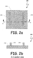
- FIG. 2a schematically illustrates a simplified portion of a block diagram with relevant elements of a die 200 having rules adhered to its surface.
- the die 200 may comprise a body 210, and a plurality of rules, such as rules 212 and 214, for example.
- Surface-adhesive rules 212 and 214 may be of different types. Exemplary rule types may be: cutting; creasing; embossing rules etc.
- Rules 212 and 214 are made of polymeric material, which may be a gel or liquid like material that can flow before it has been polymerised.
- the flowable material may include one or more different types of polymers and/or different combinations of polymers. Exemplary polymers that may be used include, but are not limited to: polyester, polyamide, polycarbonate, polyurethane, acrylic, polypropylene, polyethylene, etc.
- the flowable material may include one or more additives.
- the additives may include, but are not limited to: silica, ceramics, metal, various fibres, different fillers, etc.
- Exemplary embodiments rule may comprise several layers (co-layer), and each such layer be constructed from a different material or, one or more layers may be constructed from different material.
- the rules 212 and 214 may have a strong enough sustainability, firmness, inside-cohesion, robustness, and/or lifespan to withstand the pressure and harsh operation of high pressure press force in one or more directions on the rule during the cutting/creasing/embossing operation of numerous cardboards.
- the pressure press force may be around a few tons, for example 1 -10 ton pressure press force.
- the flowable material may have additional attributes that may include, but are not limited to: flexibility, tackiness, spreading capabilities, required thickness, etc.
- additional attributes may include, but are not limited to: flexibility, tackiness, spreading capabilities, required thickness, etc.
- Different ingredients in the flowable material, and the ratio between these ingredients influence the presence and/or ranges of the different attributes.
- Exemplary ingredients may include, but are not limited to: different polymers, silica, ceramics, fillers, fibre etc.
- the flowable material of the rule may be: thermoplastic polymers, thermosetting polymers, metal, a combination of them, and so on.
- Exemplary flowable material may comprise: Polyurethane, having a hardness of 60 - 99 shore A, preferably, 80- 99 shore A or Polypropylene, etc.
- the viscosity of the material as deposited (drawn) may be between 1 ,000 cps and 145,000 cps, preferably between 17,000 cps and 80,000. cps, etc.
- the rule may be a cutting rule.
- the edges of the rule may be milled in order to form a sharpened edge adapted for cutting, for example. The milling may be done by mechanical or optical equipment.
- the rules may be have a hardness of 85 shore A and more or 35 shore D and more. Exemplary materials that may be used are: polymers loaded with glass fibre, carbon fibre, Kevlar fibre or fillers like silica, metal, carbon black etc.
- the exemplary body 210 of the rule die 200 may be made of, or comprise, a flexible film.
- the flexible film may include one or more types of polymers. Exemplary polymers that may be used include, but are not limited to: polyester, polyamide, polycarbonate, and/or a combination of one or more of these polymers as well as other polymers and non-polymers.
- the flexible film may include one or more additives. The additives included in the flexible film may include, but are not limited to: silica, ceramics, metal, different fillers, etc.
- Exemplary embodiments of the flexible film may have one or more layers and, each layer may utilize or contain a different material than one or more of the other layers. In some exemplary embodiments, the flexible film may be a commercial one.
- Exemplary flexible films that may be used in the body 210 of rule die 200 may include, but are not limited to: PET (Polyethylene terephthalate), PA (Polyamide), polypropylene, stainless steel, Aluminium (Al) and/or a combination of one or more of these materials as well as others. Exemplary suppliers for such materials are: HA ITA. Company (an Israeli company), S C Company, ALCAM VAW Company, etc. Some exemplary embodiments of the body 210 of the rule die 200 may be comprised of a combination of two or more flexible films.
- Exemplary combinations may include, but are not limited to: 23 micron thickness of PET associated to 25 micron thickness of Al; and/or 25 micron thickness of PET associated to 25 micron thickness of Al; and/or 36 micron thickness of PET associated to 45 micron thickness of PA; and/or 23 micron thickness of PET associated to 15 micron thickness of PA and 18 micron thickness of Al; etc.
- the body 210 of the rule die may be associated with, adhered to or otherwise combined with a substrate made of material other than flexible film. These other materials may include, but are not limited to: metal, wood, plastic, etc. Furthermore, the body 210 of the rule die may have a flat, cylindrical or other shape. In addition, the body 210 of the rule die may be flexible such that its shape can be changed, for example from flat to cylindrical by wrapping around a drum, for example.
- the body 210 of the rule die may have a strong enough sustainability, firmness, inside-cohesion, robustness, and/or lifespan to withstand the pressure and harsh operation which can be around a few tons of press force (1 - 10 ton, for example) in one or more directions during the cutting/creasing/embossing operation of the cardboards.
- the body 210 of the rule die may be made of material other then flexible film, and/or a combination of various materials.
- the flexible film may have additional attributes such as being tacky, spreadable, meeting required thicknesses, etc.
- Different ingredients in the flexible film, and the ratio between these ingredients influence the ratio or the characteristics of the different attributes.
- Exemplary ingredients may include, but are not limited to: different polymers, silica, ceramics, fillers, fibre etc.
- FIG. 2b depicts a cross-sectional view of the exemplary rule die 200 taken at line A-A.
- Exemplary rule 212 and rule 214 may be bonded to the surface of the body 210 of the rule die by adhesion.
- Exemplary adhesion techniques may include using an intermediate adhesive material between the rule (212 and/or 214) and the surface of the body 210 of the rule die.
- Intermediate adhesive materials may include, but are not limited to: Adcote 81 1 of DOW company, 238A + catalyst of MORCHEM company, etc.
- Adhesive attributes may include, but are not limited to: epoxy, oligomer, silicone acrylate oligomer, adhesion promoter, photoinitiator.
- the bonding may be done by hardening, such as thermal curing, chemical curing, UV curing, etc.
- a combination of two or more techniques may be implemented and other techniques are also anticipated.
- FIG.3a schematically illustrates a simplified diagram with relevant elements of an exemplary rule die 300a.
- the rule die 300a may comprise a body 310 and a rule 312.
- the rule 312 may be adhered to the surface of the body 310.
- FlG.3b schematically illustrates a simplified diagram with relevant elements of an exemplary rule die 300b, in which the shape of a rule 314 may comprise a wide base 318, and a rounded-shape top edge 316.
- the wide base 318 may improve the bonding of the rule 314 to the body 310 of the rule die 300b.
- the wide base 318 may further enhance the ability of rule 314 to withstand the numerous forces that may be applied during cutting/creasing/embossing operations.
- the shape of the top edge of the rule 314 may match the functionality of the rule 314.
- the rounded-shape edge 316 may be used for creating crease lines on the surface of a cardboard.
- FIG. 3c illustrates another embodiment of a rule die 300c.
- the illustrated rule die 300c comprises a rule 320 with a sharp top edge 322.
- the shape of the top edge of the rule 320 may match the functionality of the rule 320.
- the sharp edge 322 may be used for creating cutting lines on the surface of a cardboard.
- the rule 320 may further comprise shoulder-like sides 324.
- the shoulder-like sides 324 enhance the ability of the rule 320 to withstand the numerous forces during cutting/creasing/embossing operations.
- the sharp edge may be achieved by further milling (scraping) the edge after hardening the rule.
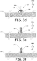
- FIG.3d schematically illustrates yet another simplified diagram with relevant elements of an exemplary rule die 300d.
- the rule die 300d comprises a co-layer rule 326.
- the co-layer rule 326 may be comprised of three different types of layers, for example. One type of a layer for the base 330, another type of a layer for the shoulder-like sides 328, and a third type of a layer for the rest of the body of the rule 329 and its top edge.
- Each of the co-layers in the illustrated rule 326 may be made of different materials or, one or more co-layers may be different from the other co-layers.
- Each co-layer may have a different: shape; cross-section; width; comprise different polymer types and/or additives; etc.
- Each co-layer may also have different required attributes.
- the lower base layer 330 may be required to have better adhesive attributes
- the highest layer 329 may be required to have more elastic attributes
- the shoulder-like sides may be required to have more firmness attributes 328, and so on.
- Other exemplary embodiments of co-layered rules may have a different number of co-layers and different configurations of shapes and attributes.
- FIG. 3e illustrates yet another exemplary embodiment of a rule die 300e.
- the illustrated rule die 300e comprises a rule 332 with an asymmetrical shape.
- Rule 332 may be comprised of a one shoulder-like side 334 and an asymmetrical base 336, for example.
- An asymmetrical rule may be used when drawing adjacent rules.
- FIG. 3f illustrates an exemplary embodiment of a rule die 300f.
- the rule die 300f may be comprised of a rule 338 with a trapezoid-like shape top edge 340.
- the trapezoid-like shape top edge 340 may be used as a cutting rule in a rotary system, for example.
- FIG. 4 is a schematic diagram with relevant elements of a portion of a rotary rule die forming system 400.
- the rotary system 400 may be used for drawing a plurality of rules 460-463 on the surface of a rule die's body 420.
- the rules 460-463 may protrude from the surface of the rule die'S body 420 and may have different shapes and sizes.
- the rules 460-463 may be functional and configured for cutting, creasing, embossing, etc. and/or a combination of two or more of these functions.
- the rotary system 400 may include a drum 410 on which the rule die's body 420 may be positioned.
- the body 420 of the rule die may be associated with, or joined to, the drum 410 using a variety of techniques including, but not limited to: adhesion, grippers, moulding, coating, etc.
- the body 420 of the rule die may be removed from the drum 410 after the rules 460-463 are created.
- the body 420 of the rule die may be left on the drum 410, to be used for cutting/ creasing/embossing cardboards operations in a rotary system, for example.
- rotary system 400 may include one or more drums.
- a similar rotary system 400 may be used for producing a counter die.
- the counter die may be associated with the drum 410 in a similar ways as described elsewhere herein with regards to the body 420 of the rule die.
- the rotary system 400 may produce one flexible film layer to act as a counter die.
- the rotary system 400 may include a plurality of different flexible film layers to act as a counter die.
- the rotary system 400 may produce only portions of the surface of the counter die's body, and so on.
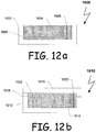
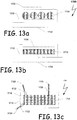
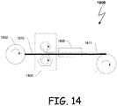
- Other exemplary embodiments of producing a counter die are disclosed in conjunction with the description of FIGs. 12 , 13 and 14 for example.
- Exemplary rotary system 400 may roughen the surface of the counter die's body and/or the surface of the body 420 of the rule die using different tools. These tools may include, but are not limited to: a scraper, a laser, etc. Further, the rotary system 400 may engrave a desired layout of trenches with a laser or mechanical tool, for example. In alternative exemplary embodiments, the counter die body's surface may not cover the entire surface of the die's body. For example, it may be just two raised areas. The two raised areas may be drawn, moulded, coated, etc.
- the counter die's body and/or the rule die's body 420 may be made of flexible film.
- the flexible film may include one or more types of polymers. Exemplary polymers that may be used include, but are not limited to: polyester, polyamide, polycarbonate, and a combination of these or other polymers or polymer like substances.
- the flexible film may include one or more additives. These additives may include, but are not limited to: silica, ceramics, metal, different fillers, etc. Exemplary embodiments of the flexible film may comprise several layers. Each layer may comprise different materials.
- the flexible film of the counter die body may have a strong enough sustainability, firmness, inside-cohesion, robustness, and lifespan to withstand the pressure and harsh operation which can be around a few tons of press force in one or more directions during the cutting/creasing/embossing operation of the cardboards.
- the counter die body may be associated with a substrate made of other material. These materials may include, but are not limited to metal, wood, plastic, etc.
- the rule 460-463 on the body 420 of the rule die may be flexible enough to bend even after hardening, but still rigid enough to serve their purposes of cutting, creasing and/or embossing.
- Rotary system 400 may further include one or more extrusion heads.
- Exemplary embodiments of the extrusion head may comprise: a drawing head 435, a controller 470, and one or more rails 430.
- the drawing head 435 may comprise: at least one nozzle 440, at least one cartridge 445 fluidly associated with the nozzle 440.
- the nozzle 440 may be associated with the rail 430.
- the nozzle 440 may slide upon the rail 430.
- the cartridge 445 is associated with the rail 430 as well.
- the cartridge 445 may be independent from the rail 430.
- Cartridge 445 may comprise flowable material that will be output by nozzle 440, thus drawing rules 460-463.
- the cartridge 445 and the nozzle 440 may be associated with or controlled by a motor for moving the cartridge 445 and/or nozzle 440 back and forth on rail 430 in a direction indicated by arrow 450.
- the nozzle 440 may be adapted to rotate in the directions indicated by arrows 452.
- nozzle 440 may also move up and down in the directions indicated by arrows 454.
- the drawing head 435 may be used as a single unit, while in other embodiments the nozzle 440 and/or the cartridge 445 may be moved independent from each other.
- Drum 410 may be adapted to rotate in a counter-clockwise direction indicated by arrow 455.
- drum 410 may rotate in a direction opposite to the direction indicated by arrow 455 (i.e., clockwise), and yet in some exemplary embodiments, the drum 410 may rotate in both directions. Further, the drum 410 may also be configured to move laterally in relationship to the rail.
- the controller 470 may operate to control and coordinate the movement and operations of the different modules or elements, as well as the operations of the rotary system 400. For instance, the controller 470 may operate to control the rotation of the drum 410, the movement of the nozzle 440 and the cartridge 445; etc.
- the controller 470 may also instruct and control the nozzle 440 and cartridge 445 to deposit flowable material on die's body 420 in order to draw a desired layout of rule 460-463.
- the nozzle 440 may output flowable material while moving in different directions.
- Exemplary directions may include, but are not limited to: directions indicated by arrows 450, 452 and/or 454 on rail 430 while drum 410 may move in the direction 455 and/or opposite to 455 as well as other directions.
- drum 410 may move in a direction 455 (or opposite to this direction) while the nozzle 440 may remain in place.
- the nozzle 440 may be moved in direction 450 to draw rule 462 while the drum 410 may remains stationary.
- the rule 462 can be drawn by moving the drum 410 in the direction of arrow 450 while the nozzle 440 remains stationary.
- rule 462 can be drawn by moving the drum 410 in one direction along the path of arrow 450 and moving the nozzle 440 in an opposite direction.
- the rules 460-463 may be drawn in one continuous deposition of flowable material by nozzle 440.
- the rules 460-463 may be drawn by depositing a plurality of layers, each layer may comprise different flowable materials.
- the drum 410 may rotate several times about its axis while the nozzle 440 may move a single time on rail 430. In other embodiments, the drum 410 may rotate a single time around its axis while nozzle 440 moves several times in different directions.
- the nozzle 440 may be moved along rail 430 at the same time as drum 410 rotates to draw a diagonal and/or curved rule.
- the speed and/or direction of rotation and/or movement of the nozzle 440 may depend on: the type and form of flowable material output, and the section of the rule 460- 463 being drawn, the layout, etc.
- the speed and/or direction of rotation and the movement of the nozzle 440 may be controlled by controller 470, for example.
- the flowable material deposited by the nozzle 440 may include one or more different types of polymers or different combinations of two or more polymers or material having similar characteristics.
- Exemplary polymers that may be used are: polyester, polyamide, polycarbonate, polyurethane, acrylic, polypropylene, polyethylene, etc.
- the flowable material may include one or more additives.
- the additives may include, but are not limited to: silica, ceramics, metal, various fibres, different fillers, etc.
- the flowable material of the rules may comprise several layers (co-layers). Each layer may be made of different materials and/or each layer may have a different: shape; cross-section; width; comprise different polymer types and/or additives; etc. Each layer may also have a different required set of attributes. More information on layers of the rule is presented herein in conjunction with the description of FIG. 3d and FIGs 9a-b .
- the flowable material output by the nozzle 440 may be hardened after and/or while the drawing is being performed.
- the hardening may be accomplished by a hardener 480.
- the hardener 480 may irradiate energy that can cause the drawn flowable material to harden and/or adhere. Irradiated energy may include, but is not limited to: ultra violet (UV) light, visible light, heat, etc. Alternatively, cooler air may be directed at the drawn flowable material to cool and thus harden the material.
- UV ultra violet
- cooler air may be directed at the drawn flowable material to cool and thus harden the material.
- the type of energy irradiated by the hardener 480 generally depends on the type of flowable material and the hardening characteristics of that material. For example, when the flowable material is a thermosetting material, heat may be applied by the hardener 480. When the flowable material is a thermoplastic material, the hardener 480 may cool the material in order to harden it. Yet when the flowable material is comprised of photo-initiator ingredients, the hardener 480 may illuminate UV lighting in order to harden the flowable material. Optionally, when one or more flowable materials utilized, one or more types of hardeners 480 may be used.
- the hardener 480 may be positioned adjacent to the nozzle 440 such that the flowable material may be hardened immediately after it is drawn. In other exemplary embodiments the hardener 480 may be positioned at a distance from the nozzle 440. In some embodiments, the hardener 480 may not be provided in rotary system 400 and rule 460-463 may be hardened by another system. In yet other exemplary embodiments, no hardener 480 may be used.
- the hardener 480 may be used for pre-treatment.
- the pre-treatments may include, but are not limited to: ozone showers, primer coatings, surface roughening, etc.
- the hardener 480 may comprise different modules (not shown in drawings). Exemplary modules include but are not limited to: laser beams, UV flash light, cartridge(s) with primer substances, cartridge(s) with adhesive substances, and so on.
- the hardener 480 and its modules may be controlled by the controller 470, for example.
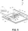
- Fig. 5 illustrates an exemplary portion with relevant elements of a flat rule die forming system 500.
- the flat system 500 may be used for drawing an exemplary rule 560 on the surface of a rule die's body 520 that it may be positioned on a flat substrate 510.
- the flat system 500 may include one or more extrusion heads.
- Exemplary embodiments of the extrusion head may comprise: a drawing-head 535, a controller 570, and one or more rails 530.
- the drawing-head 535 may comprise: at least one nozzle 540 and at least one cartridge 545 associated with or coupled to the nozzle 540 for fluid communication.
- the rule 560 may be drawn by the at least one nozzle 540 associated with the at least one cartridge 545.
- the nozzle 540 may further be associated with a motor to cause the nozzle 540 to traverse along the rail 530 in the directions of arrow 550, for example.
- the nozzle 540 may also be adapted to rotate in directions illustrated by arrows 552 and/or 554.
- the rail 530 may be situated between two rails 535, substantially perpendicular to rail 530 and is adapted to travel in the directions of arrow 555.
- Control 570 may be adapted to control the movement and coordinate the different modules of the flat system 500.
- the controller 570 may control one or more of the nozzle 540, the rail 530, the cartridge 545, etc.
- the flat system 500 may further include a hardener 580 for hardening and/or adhering the rule 560 to the surface of the rule die's 520 body, similar to hardener 480 shown and described in conjunction with the description of FIG. 4 .
- flat substrate 510 may be adapted to move in the directions depicted by arrow 555.
- the configurations allow the nozzle 540 and the body 520 of the rule die to be moved relative to each other sufficiently to cover the required area of the body 520 of the rule die, and to deterministically draw the rules, then the configuration is foreseen.
- the rule die's body 520 may be bent around a cylindrical drum, after the deposition of the rules.
- the flat system 500 and rotary system 400 may be similar in their functionality.
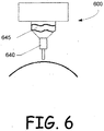
- Fig. 6 depicts relevant elements of an exemplary embodiment of a drawing-head 600.
- the drawing-head 600 may be comprised of a nozzle 640 for depositing flowable material.
- the nozzle 640 may be associated with or fluidly coupled to a cartridge 645.
- the cartridge 645 contains flowable material and is associated with a pressure actuator (not shown in the drawing) for depositing the flowable material by injecting it or forcing (i.e. extruding) it through the nozzle 640 to draw a desired rule.
- the nozzle 640 and its orifice may have various shapes. More information on the different shapes and orifices is disclosed in conjunction with the description of FIGs 7a-b .
- FIG. 7a is a schematic illustration of relevant elements of an exemplary nozzle700a.
- the exemplary embodiment of the nozzle 700a includes a first tube 742 that may be substantially perpendicular to the body 740 of the rule die.
- a second tube 744 may be oriented substantially perpendicular to the first tube 742 and parallel to the body 740 of the rule die.
- the tube 744 has an orifice 746 at its end through which flowable material may be output toward the body 740 of the rule die.
- the orifice 746 may have different cross-sectional shapes.
- the cross-sectional shapes of the orifice may be determined according to the required rule profile, for example.
- Exemplary cross-sectional shapes of the orifice 746 may match the profile of the rules depicted in FIG. 3a-f , for example.
- Fig. 7b is a schematic illustration of relevant elements of another exemplary nozzle 700b.
- the exemplary embodiment of the nozzle 700b may include a tube 752 that is oriented substantially perpendicular to a rule die's body 750.
- the tube 752 may include an orifice 756 through which flowable material may be output toward the body 750 of the rule die.
- the orifice 756 may have various shapes as described in conjunction with orifice 746 of FIG. 7a .
- the tube 752 may be closed at its distal end 758, and the material may be released substantially parallel to rule die's body 750, through opening 756.
- distal end 758 may be open and the flowable material may be output in a substantially perpendicular manner through distal end 758 as well as through 756, and so on.
- substantially perpendicular is meant to include an angle may be in the range of 90 degree plus/minus 30 degrees.
- nozzles may be used in accordance with embodiments of the present disclosure.
- nozzles manufactured by Nordson Corporation which can be viewed on their website (www.nordson.com) may be utilized.
- the types of nozzles used may differ according to: the material that is being output onto the rule die, the required shape of rule, etc.
- the orifice of the nozzle may be directed in a direction opposite to the relative direction of motion of the nozzle with respect to the surface of the rule die's body 750.
- the orifice of the nozzle may be parallel to the surface of the rule die's body 750.
- the nozzle may be at a pre-defined angle to the surface of the rule die's 750. Exemplary angles may be at the range of 45-135 degree.
- FIG. 8a schematically illustrates a simplified diagram with relevant elements of an exemplary pressure actuator 800a.
- the pressure actuator 800a may, for example, be an air-pump actuator.
- a cartridge 810 containa flowable material 814 that may be used to draw rules.
- the cartridge 810 has an output 816 through which the flowable material 814 may be discharged or used to fluidly couple the cartridge 810 to a nozzle.
- the cartridge may have an input 812 through which air may be compressed and thus press the material out of the cartridge's output 816 via a nozzle (not shown in drawing) according to a rule layout.
- the air may be compressed by a piston 808, for example.
- the piston 808 may be controlled by a controller similar to the controller 470 of rotary system 400 and/or controller 570 of flat system 500.
- Pressure actuators 800a may have suction capabilities as well.
- FIG. 8b schematically illustrates a simplified diagram with relevant elements of exemplary pressure actuators 800b.
- the pressure actuator 800b in this embodiment is an electrical cogwheel pump.
- the cartridge 810 and flowable material 814 may be similar to that as described for the cartridge 810 and flowable material 814 in FIG. 8a .
- the flowable material 814 is carried by a cogwheel 822 out of the cartridge output 816.
- the cogwheel 822 may be actuated by an electric/step motor 818, for example.
- the operation of the cogwheel 822 and the motor 818 may be controlled by a controller similar to controller 470 of rotary system 400 and/or controller 570 of flat system 500.
- the flowable material may be output from the cogwheel's 822 output 820 to a nozzle (not shown in the drawing) according to a rule layout.
- Pressure actuator 800b may have suction capabilities as well.
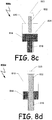
- FIG. 8c schematically illustrates a simplified diagram with relevant elements of an exemplary pressure actuator 800c.
- the pressure actuator 800c in this embodiment is a screw-piston pump.
- the screw-piston pump is comprised of a screw 822 associated with a plate 824, and an engine or motor 823, for example.
- Cartridge 810 and flowable material 814 may be similar to the cartridge 810 and flowable material 814 described in FIG. 8a .
- the flowable material 814 may be pressed out of the cartridge output 816 by the screw-piston pump as the screw 822 is screwed by the engine 823, thus causing the plate 824 to press the flowable material 814 out of the cartridge 810 output towards a nozzle (not shown in drawing) according to a rule layout.
- the operation of the screw-piston pump 800c may be controlled by a controller similar to controller 470 of rotary system 400 and/or controller 570 of flat system 500.
- the screw-piston pump 800c may have suction
- FIG. 8d schematically illustrates a simplified diagram with relevant elements of an exemplary pressure actuator 800d.
- the pressure actuator 800d is a screw pump 832.
- the cartridge 810 and flowable material 814 may be similar to the cartridge 810 and flowable material 814 described for FIG. 8a .
- the flowable material 814 may be carried out between the spindles of the screw 832 toward the cartridge output 816 and towards a nozzle (not shown in drawing) according to a rule layout by the screw pump 832 as the screw pump 832 is screwed by an engine 833.
- the operation of the screw pump 832 may be controlled by a controller similar to controller 470 of rotary system 400 and/or controller 570 of flat system 500.
- the screw pump 832 may have suction capabilities as well.
- FIG. 8e schematically illustrates a simplified diagram with relevant elements of an exemplary pressure actuator 800e.
- the pressure actuator 800e is a screw pump 832.
- the pressure actuator 800e may be similar to the pressure actuator 800d described in conjunction with FIG. 8d .
- the pressure actuator 800e further comprises a cut-off mechanism.
- the cut-off mechanism compriseds a tube 842 in which pulses of air, liquid, etc. may pass through in the direction of arrow 844.
- the air, liquid, etc. pulses may be created by a pulse-pump 843 associated with the tube 842, for example.
- the cut-off mechanism may further comprise a switch/valve that may be controlled by a controller similar to controller 470 of rotary system 400 and/or controller 570 of flat system 500.
- the pulse-pump 843 may be controlled by the controller, as well.
- the switch/valve may comprise a shutter arm 846 or may be a ball valve or other structure.
- the switch/valve may have two modes. One mode may be an open-mode in which the shutter arm 846 is substantially parallel to tube 842. The second mode may be a closed-mode in which the shutter arm 846 is substantially perpendicular to tube 842 or oriented in a manner to prevent flow.
- the cut-off mechanism when the cut-off mechanism is activated, at the end of a rule drawing for example, the following actions may take place: output of the flowable material by screw-pump 832 is stopped; the screw-pump 832 may be screwed in the counter-clockwise direction (or retracted); the shutter arm 846 is switched to open- mode in the direction similar to arrow 848; a pulse of air, liquid, etc. may be created and output from the pulse-pump 843 in direction of arrow 844. In other exemplary embodiments one or more shutter arms or valves may be used.
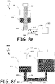
- FIG. 8f schematically illustrates a simplified diagram with relevant elements of an exemplary pressure actuator 800f.
- the pressure actuator 800f may be similar to pressure actuators 800a-e described in conjunction with FIGs. 800a-e.
- the pressure actuators 800f may further comprise a filling mechanism.
- the filling mechanism may comprise a reservoir 856 that may contain flowable-material 814; a tube 858 in which the flowable material may pass through; and a switch/valve that may be controlled by a controller similar to controller 470 of rotary system 400 and/or controller 570 of flat system 500.
- the switch/valve may comprise a shutter arm 854.
- the switch may have two modes. One mode may be open-mode in which the shutter arm 854 is substantially parallel to tube 858 and may shut aperture 860. The second mode may be closed-mode in which the shutter arm 854 is substantially perpendicular to tube 858 or oriented such that the flow from tube 858 is restricted.
- the filling mechanism when the filling mechanism is activated, and the cartridge 810 is required to be filled with flowable material 814 for example, the following actions may take place: output of the flowable material from output 816 is stopped; piston 808 may be pulled outward from cartridge 810; the shutter arm 854 may be switched to open-mode in the direction similar to arrow 852; flowable material may be output from the cartridge 856 toward the shutter arm 846. In other exemplary embodiments one or more shutter arms may be used. In other embodiments the cartridge 810 may be filled through opening 812, for example. The cartridge 856 may be easily and quickly disconnected from tube 858, and replaced with another one, for example. The Cartridge 856 and its flowable material may be purchased by the owner of the a rule die forming system.
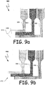
- Fig.9a depicts a simplified diagram with relevant elements of an exemplary embodiment of a multiple-compartment cartridge 900.
- the multiple-compartment cartridge 900 may be used to draw a co-layer rule, for example.
- the multiple-compartment cartridge 900 comprises a plurality of compartments 902, 904, and 906.
- Each compartment comprises a cartridge and a pressure actuator (not shown in the drawings).
- Each compartment 902, 904, and 906 may contain, separately, one or more ingredients of flowable material.
- each compartment may comprise a different flowable material, for a different layer of the co-layer.
- the cartridge 900 may further comprise a combiner 908. to combine the different ingredients and/or flowable material.
- the combiner 908 may comprise a slot/aperture 910 through which the combined material from the different compartment 902, 904, and 906 may be output.
- a controller, 470 ( FIG. 4 ) and/or controller 570 ( FIG.5 ), may control the quantities of each ingredient/material/layer.
- one or more of the different compartments 902, 904, and 906 may comprise adhesive substance.
- the combiner 908 may include an agitator (not shown) to facilitate the mixing and combining of the materials from two or more of the different compartments 902, 904, and 906.
- the different layers may be bonded to one another during different hardening techniques, for example.
- Exemplary hardening techniques include, but are not limited to: temperature treatment, Ultra- Violet (UV) curing, visible light, infra red light, chemical curing, cooling etc.
- the different layers may be bonded by an adhesive.
- an adhesive substrate layer compartment may be placed between the compartments comprising the layers that will need to be adhered.
- the bonding may be a combination of the above techniques.
- Fig.9b schematically illustrates a co-layer creation by an exemplary embodiment of a multiple-compartment cartridge 910.
- the multiple-compartment cartridge 910 comprise a plurality of compartments 912, 914, and 916.
- the compartment 916 may be the leading edge of the drawing head 910.
- Each compartment may comprise a cartridge and a pressure actuator (not shown in the drawing).
- each compartment may comprise a different flowable material, for a different layer of the co-layer, and so on.
- a controller, 470 ( FIG. 4 ) and/or controller 570 ( FIG.5 ), may control the co-layer drawing, for example.
- one or more of the different compartments 912, 914, and 916 may comprise adhesive substance.
- the multiple-compartments cartridge 910 may have a stair-like shape edge.
- the co-layer may be created in phases.
- An exemplary phase technique includes, but is not limited to: drawing a first layer on the surface, next drawing on top of it the next layer and so on.
- This exemplary embodiment may comprise a plurality of cartridges. Each cartridge may comprise a different material for a different layer and/or adhesive substance.
- the controller may control the operation.
- a combination of the different co-layer techniques and multiple- compartments cartridge may be used.
- FIGs. 10a-d schematically illustrates a flowchart showing relevant processes or actions of an exemplary rule drawing method 1000.
- the illustrated rule drawing method 1000 may be executed by a controller, a microprocessor, a micro-controller, a computer or any other processing device including (collectively referred to as a controller), but not limited to controllers similar to controller 470 ( FIG. 4 ) and/or controller 570 ( FIG.5 ).
- the method 1000 may be initiated 1002 upon powering on the controller but, it will be appreciated that the method 1000 may be initiated or invoked from other processes, system, events, user actions, etc..
- the controller may operate to detect the various modules in the system or, the various modules or other processors may provide information to the controller to identify the different modules.
- Exemplary modules may include, but are not limited to: drawing head modules, different registers, different timers, etc. After being invoked the process may then act to reset, initialise or determine the state of various resources, registers, variables, memory components, etc. 1004.
- the various resources may include, but are not limited to: timers (t), counters (R), distance measurers (D), and so on.
- the rule drawing method 1000 may enter into a delay loop waiting for the reception of an initiation command 1006.
- the initiation command directs the rule drawing method 1000 to commence the creation of a rule die.
- the method 1000 may proceed to step 1008 by receiving or obtaining the entry of various inputs or parameters used in the creation of rule die.
- the inputs may be received, obtained or entered by a user, provided by a processor or other entity, read from an electronic file, etc. Exemplary inputs may include, but are not limited to: the depth or thickness of the cardboard that will be pre-treated while using the rule die, the type of rule that will be required, the requested layout, and so on.
- the method 1000 may check 1010 a look-up table for information on the required job description.
- Exemplary information may include, but is not limited to: the definition of flow index for each rule, the definition of profile for each rule, the definition of the layers for the co-layers, the type of rule (cutting/embossing/creasing), etc.
- the method decides whether additional information in the look-up table has been found or is available 1012. If additional information is not found 1012, then method 1000 may prompt the user or other information provider to enter or provide the information 1014, and processing then returns to step 1008 to check for this information. If the method obtains the information in the look-up table or otherwise 1012, then the method 1000 may proceed to step 1018. The method 1000 may then proceed to execute a rule drawing loop that comprises the acts listed in steps 1018 through 1046 ( FIG. 10d ). The first action in the rule drawing loop comprises increasing counter R by one (incrementing R) 1018, and the method 1000 may begin drawing a rule in accordance with the information received at step 1010 and layout requirements.
- the method continues by adjusting or setting the height and angle of a nozzle at 1020.
- the velocity of the drawing head modules may be accelerated 1020 to a required velocity V1 by acceleration rate a1.
- the pressure applied by one or more pressure actuators may also be raised at 1020 to a required pressure P1, and so on.
- screw-pumps instead of raising pressure P1, a screwing speed is raised.
- the method 1000 may proceed to step 1022 at FIG. 10b .
- the method continues by entering a delay loop 1022 until the value of timer t is equal to t1.
- the value of t1 may be calculated according to the mechanical capabilities of the drawing-head and the length required for the rule or rule segment according to the layout.
- timer t value is equal to the value of t1
- the acceleration rate a1 of the velocity of the drawing head modules may be stopped 1024 and the raising of the pressure of the pressure actuator may be stopped 1024 as well.
- the drawing head modules may continue drawing at velocity V1 and the pressure actuator may continue pressing at pressure P1.
- a distant measurement D may be used instead using a timer.
- the distant measurement D may be expressed by a number of steps given to a step-motor or by feedback received from a step measurement encoder associated to the drawing head.
- the method 1000 may enter into a delay loop until the value of counter t is equal to t2 at step 1026, where t2 may be calculated from inputs on the drawn pattern of the rule and the velocity that was reached at t1.
- the velocity of the drawing head modules may be decelerated in step 1028 to V2 at deceleration rate a2, and the pressure by the pressure actuator may be decreased in step 1028 to P2.
- the nozzle may be 1030 elevated X mm and turned in step 1030 to an angle O according to the requirements of the layout.
- the nozzle may be lowered Z mm (wherein Z may equal X).
- the method 1000 continues by accelerating the drawing head modules to a velocity of V1 at an acceleration rate of al, and the pressure of the pressure actuator may be raised to P1 in step 1032.
- the drawing head modules may continue to draw in step 1032 the rules according to the layout.
- the method 1000 may then proceed to step 1034 at FIG. 10c .
- the method 1000 continues at step 1034 of FIG. 10c by entering a delay loop until the value of the timer t is equal to t3 in step 1034.
- the acceleration of the velocity of the drawing head modules and the raising of the pressure by the pressure actuator may be stopped 1036.
- the drawing head modules may continue drawing at velocity V1 and the pressure actuator may continue at pressure P1 in step 1036.
- the method 1000 may enter a delay loop until the value of timer t is equal to t4 in step 1038.
- the pressure imposed by the pressure actuator may be stopped 1040, and the motion of the drawing head modules may be stopped 1040 as well.
- the nozzle may be elevated to a desired level by raising it Y mm and spun sharply 1042 at by a certain of number degrees (180-360 degrees for example) about its centre. The spinning of the nozzle operates to cut the flowable material from the nozzle.
- an air-pulse may be used in order to cut the flowable material from the nozzle as disclosed above in conjunction with the description of FIG. 8e , for example.
- a shutter may be used as disclosed in FIGs. 8e-8f .
- a guillotine may be utilized to cut the flowable material from the nozzle, or an air knife may be used to cut the flowable material from the nozzle at once, and so on.
- the method 1000 may then proceed to step 1044 at FIG. 10d .
- the method 1000 may provide a notice or indicator in step 1044, such as by turning on a light, making a sound or placing text or icons on a display as non-limiting examples, that the rule has been drawn.
- the method 1000 determines whether all of the rules have been drawn and the job has been finished (step 1046). If the job is finished in step 1046, then the method 1000 may provide a notice or indicator (step 1048), such as by turning on a light, making a sound or placing text or icons on a display for example, that the job as been finished and method 1000 may end. If the job has not yet been finished and more rules need to be drawn (step 1046), then method 1000 may return to step 1018 at FIG. 10a to start drawing the next rule.
- FIG. 11 depicts a schematic illustration of relevant elements of yet another exemplary rule die forming system 1500.
- the a rule die forming system 1500 includes an engraving mechanism 1530, a rail 1550 and a nozzle 1540.
- the engraving mechanism 1530 may be any suitable device that can provide adequate engraving, such as but not limited to, a laser and/or a mechanical tool for example.
- the rail 1550 is suitable for both the nozzle 1540 and the engraving mechanism 1530 to be positioned on the surface of the rail 1540. Alternatively, the engravings may be performed in a system other than the rule drawing system.
- the engraving mechanism 1530 may be used to etch an area of the rule die 1520 to receive a rule pattern and then the nozzle 1540 can apply material for the rule within the etched areas.
- the module 1530 may be a scraper which may be used to mill/scrape the edge of a drawn cutting rule.
- the module 1530 may be a hardening module, such as but not limited to a light source, a air knife, etc.
- FIG. 12a depicts relevant elements of a portion of an exemplary embodiment of a moulding system 1600.
- Moulding system 1600 may be used in the creation a counter die body and/or a die body.
- Moulding system 1600 may comprise an open top mould 1602, into which gel/liquid like material 1604 may be input.
- the gel/liquid like 1604 material may comprise one or more different polymers.
- Exemplary polymer may be: polyurethane, monothane with shore hardness of around A30-A70 of DOW company, etc.
- the gel/liquid like material may comprise one or more different additives.
- Exemplary additives may be accelerators such as, but not limited to: Dibutyltin dilaurate.
- Other exemplary additives may be: silica, ceramics, metal, various fibres, different fillers.
- the open top mold 1602 may be coated with release coating (not shown in drawing). Exemplary release coating may be Cilrelease 905 of DOW Company.
- a flexible film 1606 may be added to be associated to the gel/liquid like material 1604.
- the flexible film 1606 may be made of different materials. Exemplary materials may be: PET (Polyethylene terephthalate), PA (Polyamide), polypropylene, stainless steel, Aluminium (Al) and/or a combination of them, etc.
- the flexible film 1606 may be added on top of the gel/liquid like material 1604, while in other embodiments it may be added at the bottom of the gel/liquid like material 1604.
- the flexible film 1606 length may exceed the open mould length, in these cases the open top mold 1602 may have fitted apertures (not shown in drawings).
- the mould with the gel/liquid like material 1604 and the flexible film 1606 may pass a hardening process.
- Exemplary hardening may be curing by heat, curing by light (UV, infra red, visible light, etc), curing by cooling, and so on.
- the temperature and time of the hardening may be according to the gel/liquid like material's 1604 composition of ingredients and/or its dimensions.
- hardening of polyurethane may be around 138°C for 6 hours.
- the hardening of polyurethane may be around 135°C for a few minutes if added to it are additives with high sensitivity to heat.
- the flexible film 1606 may be pierced 1608.
- the piercing may be done by different techniques. Exemplary techniques may be: by a puncher, a laser, etc.
- FIG. 12b depicts relevant elements of a portion of an exemplary embodiment of a closed moulding system 1620.
- Closed moulding system 1620 may be used in the creation a counter die body and/or a die body.
- Closed moulding system 1620 may comprise a closed mould 1622, into which gel/liquid like material 1614 may be input with or without a flexible film 1606, similar to the one disclosed in FIG. 12a .
- Closed moulding system 1620 may further comprise a lid 1626, and one or more excess release channels 1628.
- the gel/liquid like material 1614 may be injected into the mould 1612 by extruder points in the mould 1612 (not shown in the drawing.) or placed with or without a flexible film 1606 inside the mould 1622 when the lid 1626 is open and only then the lid may be placed closed 1626.
- the mould with the gel/liquid like material 1614 with or without a flexible film 1606 may pass hardening process.
- Exemplary hardening may be curing by heat, curing by light (UV, infra red, visible light, etc), curing by cooling, etc.
- the conditions and times of the hardening techniques may be similar to the ones disclosed in conjunction with FIG.12a .
- the mould 1622 may be coated with release coating (not shown in drawing).
- Exemplary release coating may be Cilrelease 905 of DOW Company.
- the flexible film 1606 may be pierced 1630. The piercing may be done by different techniques. Exemplary techniques may be: by a puncher, a laser, etc.
- FIG. 13a depicts relevant elements of a portion of an exemplary embodiment of a press system 1700.
- Press system 1700 may be used in the creation a counter die body and/or a die body.
- Press system 1700 may comprise a base 1708, a mould 1702, and a top 1706.
- Top 1076 may be part of a pressure actuator (a piston pressure actuator, for example).
- a plurality of materials 1704 may be input into the mould 1702.
- Materials 1704 such as, but not limited to: different polymers, additives, etc.
- Exemplary polymers may be: polyurethane, EPDM (ethylene propylene diene Monomer rubber), silicon, acrylic, etc.
- Different additives may be: Graphite, Dibutyltin dilaurate, silica, ceramics, metal, various fibres, and/or different fillers.
- the press process may comprise one or more phases.
- a first phase may comprise flattening the materials 1704 as depicted in FIG. 13b material 1710.
- This phase may comprise heating the materials 1704 and exerting pressure on them by the top 1706, for example.
- the second phase may comprise exerting higher pressure and heat and hardening the material. Hardening may be done by curing via light (UV, Infra red, visible light, etc), or by heating, or by cooling.
- Table 11 Material Type Temperature [C] Pressure [bar] Time [sec] EPDM 135 5 30 Silicone 180 8 12
- FIG. 13c depicts relevant elements of a portion of an exemplary embodiment of an injection/extruder moulding system 1720.
- Injection/extruder moulding system 1720 may be used in the creation a counter die body and/or a die body.
- Injection/extruder moulding system 1720 may comprise: a closed mould 1712, one or more injecting apertures 1722, one or more excess release channels 1718.
- Liquid/gel like material may be heated and injected 1720 with pressure to the closed muold 1712 via the one or more injecting apertures 1722.
- the liquid/gel like material may be different polymers, additives, etc.
- Exemplary polymers may be: polyurethane, EPDM (ethylene propylene diene Monomer rubber), silicon, acrylic, etc.
- Different additives may be: Graphite, Dibutyltin dilaurate, silica, ceramics, metal, various fibres, different fillers, etc.
- the mold 1712 may be coated with release coating (not shown in drawing).
- Exemplary release coating may be Cilrelease 905 of DOW Company.
- a hardening process may be implemented. Hardening may be done by curing via light (UV, Infra red, visible light, etc), or by heating, or by cooling. Exemplary conditions for the hardening for different materials are disclosed in table 11 above.
- FIG. 14 depicts relevant elements of a portion of an exemplary embodiment of a coating system 1800.
- Coating system 1800 may be used in the creation a counter die body and/or a die's body.
- Exemplary liquid/gel-like material that may be used in the coating system 1800 may be different polymers with different additives.
- Exemplary polymers may be silicon, acrylic, etc.
- Exemplary additives can be: Graphite, Dibutyltin dilaurate, silica, ceramics, metal, various fibres, and/or different fillers.
- the liquid/gel-like material may be solvent base.
- Exemplary solvent may be: MEK (Methyl Ethyl Ketone), Toluene, etc.
- Coating system 1800 may comprise: an un-winder 1802, a coating head 1806, a chamber 1808, and a winder 1812.
- Chamber 1808 may comprise an oven, a light radiator, and or a cooling mechanism, for example.
- a film 1810 may be winded on the un-winder 1802 .
- the film may be a PET (Polyethylene terephthalate), PA (Polyamide), polypropylene, stainless steel, Aluminium (Al) and/or a combination of them, etc.
- Winder 1812 may pull and wind the film on the other end of the coating system 1800.
- the film may then pass the coating head 1806.
- the coating head 1806 may coat the film with a layer of the liquid/gel-like material 1811. Next the coated film may pass through a chamber 1808 for hardening.
- the coated and hardened film may pass through a surface treatment (not shown in the drawing).
- Exemplary surface treatment may be polish, grinding, scarping, etc.
- the coated and hardened film may then be winded on the winder 1812, for example.
- the coated film may pass in a loop through the coating heads 1806 one or more chambers 1808.
- the one or more coating heads 1806 may comprise different liquid/gel-like material 1811.
- the creation a counter die's body and/or a die's body may be implemented in one or more different methods (moulding, press, coating, etc) and/or a combination of them.
- a negative pattern may be used inside the mould in order to create a required pattern and/or layout for the counter die's body and/or a die's body.
- thermoplastic material for the creation a counter die's body.
- an additional phase may be added in the creation.
- the additional phase may comprise imprinting the rules on the thermoplastic material at a required temperature. Exemplary temperature may be around 69°C.
- FIG. 15 is a functional block diagram of the components of an exemplary embodiment of system or subsystem operating as a controller or processor 1900 that could be used in various embodiments of the disclosure for controlling aspects of the various embodiments. It will be appreciated that not all of the components illustrated in FIG. 15 are required in all embodiments of the activity monitor but, each of the components are presented and described in conjunction with FIG. 15 to provide a complete and overall understanding of the components.
- the controller can include a general computing platform 1900 illustrated as including a processor/memory device 1902/1904 that may be integrated with each other or, communicatively connected over a bus or similar interface 1906.
- the processor 1902 can be a variety of processor types including microprocessors, micro-controllers, programmable arrays, custom IC's etc.
- the memory element of 1904 may include a variety of structures, including but not limited to RAM, ROM, magnetic media, optical media, bubble memory, FLASH memory, EPROM, EEPROM, etc.
- the processor 1902, or other components in the controller may also provide components such as a real-time clock, analog to digital converters, digital to analog converters, etc.
- the processor 1902 also interfaces to a variety of elements including a control interface 1912, a display adapter 1908, an audio adapter 1910, and network/device interface 1914.
- the control interface 1912 provides an interface to external controls, such as sensors, actuators, drawing heads, nozzles, cartridges, pressure actuators, leading mechanism, drums, step motors, a keyboard, a mouse, a pin pad, an audio activated device, as well as a variety of the many other available input and output devices or, another computer or processing device or the like.
- the display adapter 1908 can be used to drive a variety of alert elements 1916, such as display devices including an LED display, LCD display, one or more LEDs or other display devices.
- the audio adapter 1910 interfaces to and drives another alert element 1918, such as a speaker or speaker system, buzzer, bell, etc.
- the network/ interface 1914 may interface to a network 1920 which may be any type of network including, but not limited to the Internet, a global network, a wide area network, a local area network, a wired network, a wireless network or any other network type including hybrids.
- a network 1920 may be any type of network including, but not limited to the Internet, a global network, a wide area network, a local area network, a wired network, a wireless network or any other network type including hybrids.
- the controller 1900 can interface to other devices or computing platforms such as one or more servers 1922 and/or third party systems 1924.
- a battery or power source provides power for the controller 1900.
- each of the verbs, "comprise”, “include” and “have”, and conjugates thereof, are used to indicate that the object or objects of the verb are not necessarily a complete listing of members, components, elements, or parts of the subject or subjects of the verb and further, all of the listed objects are not necessarily required in all embodiments.
- a material or “at least one material” may include a plurality of materials, including mixtures thereof.
- unit means a standalone unit or a specialized module.
- a unit, element, and/or module may be modular or have modular aspects allowing it to be easily removed and replaced with another similar unit, element, and/or module.
- Each unit, element, and/or module may be any one of, or any combination of, software, hardware, and/or firmware.
- Software of a logical module can be embodied on a computer readable medium such as a read/write hard disc, CDROM, Flash memory, ROM, etc. In order to execute a certain task a software program can be loaded to an appropriate processor as needed.
Landscapes
- Engineering & Computer Science (AREA)
- Mechanical Engineering (AREA)
- Chemical & Material Sciences (AREA)
- Health & Medical Sciences (AREA)
- Chemical Kinetics & Catalysis (AREA)
- Medicinal Chemistry (AREA)
- Polymers & Plastics (AREA)
- Organic Chemistry (AREA)
- Life Sciences & Earth Sciences (AREA)
- Forests & Forestry (AREA)
- Application Of Or Painting With Fluid Materials (AREA)
- Making Paper Articles (AREA)
- Laminated Bodies (AREA)
- Machines For Manufacturing Corrugated Board In Mechanical Paper-Making Processes (AREA)
- Compositions Of Macromolecular Compounds (AREA)
- Adhesive Tapes (AREA)
- Coating Apparatus (AREA)
- Adhesives Or Adhesive Processes (AREA)
- Extrusion Moulding Of Plastics Or The Like (AREA)
Priority Applications (3)
| Application Number | Priority Date | Filing Date | Title |
|---|---|---|---|
| EP12193281.8A EP2581212A1 (en) | 2010-05-17 | 2011-05-17 | Method and system for surface adhesive rule technology |
| EP12193232.1A EP2581211A1 (en) | 2010-05-17 | 2011-05-17 | Method and system for surface adhesive rule technology |
| EP12193254.5A EP2578387A1 (en) | 2010-05-17 | 2011-05-17 | Method and System for Surface Adhesive Rule Technology |
Applications Claiming Priority (3)
| Application Number | Priority Date | Filing Date | Title |
|---|---|---|---|
| US34518010P | 2010-05-17 | 2010-05-17 | |
| US13/108,389 US9102818B2 (en) | 2010-05-17 | 2011-05-16 | Method and system for surface adhesive rule technology |
| PCT/IL2011/000389 WO2011145092A2 (en) | 2010-05-17 | 2011-05-17 | Method and system for surface adhesive rule technology |
Related Child Applications (6)
| Application Number | Title | Priority Date | Filing Date |
|---|---|---|---|
| EP12193281.8A Division-Into EP2581212A1 (en) | 2010-05-17 | 2011-05-17 | Method and system for surface adhesive rule technology |
| EP12193232.1A Division-Into EP2581211A1 (en) | 2010-05-17 | 2011-05-17 | Method and system for surface adhesive rule technology |
| EP12193254.5A Division-Into EP2578387A1 (en) | 2010-05-17 | 2011-05-17 | Method and System for Surface Adhesive Rule Technology |
| EP12193232.1 Division-Into | 2012-11-19 | ||
| EP12193281.8 Division-Into | 2012-11-19 | ||
| EP12193254.5 Division-Into | 2012-11-19 |
Publications (3)
| Publication Number | Publication Date |
|---|---|
| EP2572037A2 EP2572037A2 (en) | 2013-03-27 |
| EP2572037A4 EP2572037A4 (en) | 2015-12-16 |
| EP2572037B1 true EP2572037B1 (en) | 2016-12-07 |
Family
ID=44992149
Family Applications (4)
| Application Number | Title | Priority Date | Filing Date |
|---|---|---|---|
| EP11783164.4A Active EP2572037B1 (en) | 2010-05-17 | 2011-05-17 | Cutting and or creasing die and method of forming it |
| EP12193254.5A Withdrawn EP2578387A1 (en) | 2010-05-17 | 2011-05-17 | Method and System for Surface Adhesive Rule Technology |
| EP12193232.1A Withdrawn EP2581211A1 (en) | 2010-05-17 | 2011-05-17 | Method and system for surface adhesive rule technology |
| EP12193281.8A Withdrawn EP2581212A1 (en) | 2010-05-17 | 2011-05-17 | Method and system for surface adhesive rule technology |
Family Applications After (3)
| Application Number | Title | Priority Date | Filing Date |
|---|---|---|---|
| EP12193254.5A Withdrawn EP2578387A1 (en) | 2010-05-17 | 2011-05-17 | Method and System for Surface Adhesive Rule Technology |
| EP12193232.1A Withdrawn EP2581211A1 (en) | 2010-05-17 | 2011-05-17 | Method and system for surface adhesive rule technology |
| EP12193281.8A Withdrawn EP2581212A1 (en) | 2010-05-17 | 2011-05-17 | Method and system for surface adhesive rule technology |
Country Status (8)
| Country | Link |
|---|---|
| US (1) | US9102818B2 (enExample) |
| EP (4) | EP2572037B1 (enExample) |
| JP (2) | JP5969467B2 (enExample) |
| CN (3) | CN112026278B (enExample) |
| AU (1) | AU2011254215B2 (enExample) |
| CA (1) | CA2799314A1 (enExample) |
| PL (1) | PL2572037T3 (enExample) |
| WO (1) | WO2011145092A2 (enExample) |
Cited By (1)
| Publication number | Priority date | Publication date | Assignee | Title |
|---|---|---|---|---|
| EP4003697A1 (en) * | 2019-07-22 | 2022-06-01 | SEI S.p.A. | Process and device for preparing plates for cylinders to treat items of the paper processing industry |
Families Citing this family (19)
| Publication number | Priority date | Publication date | Assignee | Title |
|---|---|---|---|---|
| WO2013164812A1 (en) * | 2012-05-02 | 2013-11-07 | Highcon Systems Ltd | Method and system for stripping and blanking a cardboard |
| US9492984B2 (en) | 2012-05-02 | 2016-11-15 | Highcon Systems Ltd. | Systems and methods for treating and handling cardboard sheets |
| EP2897761B1 (en) | 2012-09-19 | 2019-01-02 | Highcon Systems Ltd | Method and system for cardboard pretreatment |
| US10315376B2 (en) | 2012-11-08 | 2019-06-11 | The C.W. Zumbiel Company | System and associated method for digital scoring of carton blanks |
| DE202012104394U1 (de) * | 2012-11-14 | 2014-02-17 | Franz Vossen | Vorrichtung zum Stanzen von blattartigen Kartonwerkstoffen |
| GB201406197D0 (en) * | 2014-04-07 | 2014-05-21 | Highcon Systems Ltd | Polymeric rule die, and formulation therefor |
| HUE039651T2 (hu) * | 2015-10-06 | 2019-01-28 | Sandvik Intellectual Property | Forgó vágó berendezés beágyazott követõ egységgel |
| ITUA20162806A1 (it) * | 2016-04-21 | 2017-10-21 | Sei S P A | Procedimento e dispositivo per la preparazione di piastre per cilindri per la cordonatura di articoli di cartotecnica. |
| GB201609363D0 (en) | 2016-05-26 | 2016-07-13 | Highcon Systems Ltd | System for impressing a relief pattern on a substrate |
| GB201609458D0 (en) * | 2016-05-29 | 2016-07-13 | Highcon Systems Ltd | System for creating a relief pattern on a substrate |
| US10974412B2 (en) * | 2016-11-15 | 2021-04-13 | Cloud Packaging Solutions Llc | Machine for cutting pouches with shaped perimeter edge, method and pouch |
| GB201702027D0 (en) * | 2017-02-08 | 2017-03-22 | Highcon Systems Ltd | Multi-orifice nozzle and uses thereof |
| KR101838253B1 (ko) | 2017-04-25 | 2018-03-14 | 주식회사 비에스피 | 플렉서블 소자 조립체 및 이의 제조방법 |
| US11541622B2 (en) * | 2017-07-06 | 2023-01-03 | Bobst Mex Sa | Creasing machine, creasing cylinder for the creasing machine and method for creasing sheets |
| ES3040533T3 (en) * | 2017-07-06 | 2025-11-03 | Bobst Mex Sa | A method of creasing sheets |
| WO2019197341A1 (en) * | 2018-04-10 | 2019-10-17 | Talens Systems, S.L.U. | Apparatus and method for processing cardboard |
| DE102018212457A1 (de) * | 2018-07-26 | 2020-01-30 | Audi Ag | Verfahren zum Herstellen einer Teilform für ein Metallbearbeitungswerkzeug |
| CN115155988B (zh) * | 2022-09-05 | 2022-11-29 | 常州铭赛机器人科技股份有限公司 | 双路稳压供胶系统及其控制方法 |
| CN117445486A (zh) * | 2023-11-23 | 2024-01-26 | 杭州爱科自动化技术有限公司 | 一种用于纸盒压痕的快速制线方法 |
Family Cites Families (68)
| Publication number | Priority date | Publication date | Assignee | Title |
|---|---|---|---|---|
| US2185885A (en) | 1938-09-13 | 1940-01-02 | George W Swift Jr Inc | Cutting mechanism |
| US3170342A (en) | 1962-08-13 | 1965-02-23 | American Can Co | Method of making cutting dies |
| US3283617A (en) * | 1964-06-01 | 1966-11-08 | Wallace J Kletzker | Process of making die cutting plates |
| CH464830A (de) | 1967-09-01 | 1968-11-15 | Contraves Ag | Einrichtung zum Ausschneiden von Folien |
| FR1548451A (enExample) | 1967-09-18 | 1968-12-06 | ||
| US3744384A (en) | 1970-02-21 | 1973-07-10 | Masson Scott Thrissell Eng Ltd | Rollers for cutting,creasing,perforating or embossing sheet materials |
| GB1310651A (en) * | 1971-04-28 | 1973-03-21 | Marechal Ets | Embossing cylinder process and product |
| US3973476A (en) | 1971-08-26 | 1976-08-10 | Olinkraft, Inc. | Cutting die for sealing corrugated board |
| JPS4737527Y1 (enExample) * | 1971-09-02 | 1972-11-14 | ||
| US3855892A (en) * | 1973-03-07 | 1974-12-24 | Cir Cut Corp | Cutting rule |
| US3884132A (en) | 1974-01-11 | 1975-05-20 | Channel Creasing Matrix Inc | Magnetically located scoring die matrix |
| US4289492A (en) | 1980-01-09 | 1981-09-15 | Container Graphics Corporation | Creasing rule |
| US5021042A (en) | 1988-11-15 | 1991-06-04 | X-Print, Inc. | Die cutting apparatus with impressible coating |
| DE3840753C3 (de) | 1988-12-03 | 1995-08-03 | Ferro Kunststoffe Gmbh | Verfahren zum Fließbeschichten eines Beschichtungsträgers |
| US5121329A (en) | 1989-10-30 | 1992-06-09 | Stratasys, Inc. | Apparatus and method for creating three-dimensional objects |
| JPH03290235A (ja) | 1990-04-06 | 1991-12-19 | Satake Tekko Kk | 厚紙の打抜き方法 |
| JP2540457Y2 (ja) * | 1991-03-29 | 1997-07-02 | 與四郎 金原 | 段ボール用折り目付けロール |
| US5194064A (en) | 1992-07-27 | 1993-03-16 | Container Graphics Corporation | Creasing rule for rotary die apparatus |
| JP3290235B2 (ja) | 1993-04-08 | 2002-06-10 | 新東ブレーター株式会社 | 研摩方法及び研摩装置 |
| DE4345128A1 (de) * | 1993-12-30 | 1995-07-06 | Detroit Holding Ltd | Vorrichtung zum Prägen |
| DE4443613C1 (de) | 1994-12-07 | 1996-04-25 | Wolfgang Prof Dr Ing Grebe | Stanzmesser mit verrundeter Schneide |
| GB2316032A (en) | 1996-08-09 | 1998-02-18 | Danisco Pack Ltd | Cutting device with indenting pad |
| US5943935A (en) | 1997-03-03 | 1999-08-31 | Atlas Die, Inc. | Lightweight dimensionally stable steel rule die |
| JPH1130920A (ja) | 1997-07-11 | 1999-02-02 | Canon Inc | 加熱定着装置及び画像形成装置 |
| EP0901155B1 (de) | 1997-09-05 | 2004-08-18 | ESEC Trading SA | Halbleiter-Montageeinrichtung zum Auftragen von Klebstoff auf einem Substrat |
| DE19756094A1 (de) | 1997-12-17 | 1999-06-24 | Winkler Duennebier Kg Masch | Verfahren zum Ausbilden einer Matrizenhohlform und Prägevorrichtung zur Durchführung des Verfahrens |
| JPH11188804A (ja) | 1997-12-26 | 1999-07-13 | Chiyoda:Kk | 抜きカス回収機構付回転式シート打抜装置 |
| CA2248840A1 (en) | 1998-09-29 | 2000-03-29 | Peter Sandford | Cutting, scoring and perforating die set and method |
| US6441338B1 (en) | 1999-04-19 | 2002-08-27 | Joshua E. Rabinovich | Rapid manufacturing of steel rule dies and other 3-dimensional products, apparatus, process and products |
| US6658978B1 (en) * | 1999-10-15 | 2003-12-09 | Ontario Die International Inc. | Steel rule die with removable cutting units |
| US6779426B1 (en) | 1999-12-21 | 2004-08-24 | Atlas Die Llc | Die rule retention device and retaining board incorporating same |
| AU2000249521A1 (en) * | 2000-04-03 | 2001-10-15 | Koji Saito | Irregularity providing device |
| DE10040683C2 (de) | 2000-08-19 | 2002-06-27 | Hinderer & Muehlich Kg | Verfahren zum Positionieren einer Patrize an einer Gegendruckwalze einer Prägestation |
| JP2002239996A (ja) | 2001-02-09 | 2002-08-28 | Sakamoto Seisakusho:Kk | 成形シートの打ち抜き装置における改良した面板構造 |
| GB2372013A (en) * | 2001-02-13 | 2002-08-14 | Photofone Ltd | Transfer printing an image onto a mobile phone casing using heat and pressure |
| AT411654B (de) | 2001-06-25 | 2004-04-26 | Boehler Ybbstal Band Gmbh & Co | Verfahren zur herstellung eines zerspanungswerkzeuges |
| EP1417539A1 (en) * | 2001-08-10 | 2004-05-12 | Paul Mayo Holt | Methods and apparatus for use in photopolymer plate manufacture |
| US20030041953A1 (en) * | 2001-08-31 | 2003-03-06 | Bba Nonwovens Simpsonville, Inc. | Method of making a bonded nonwoven web |
| JP3710448B2 (ja) | 2002-02-21 | 2005-10-26 | レンゴー株式会社 | 紙シート成形体 |
| DE10211991A1 (de) | 2002-03-18 | 2003-10-02 | Roland Man Druckmasch | Stanzvorrichtung |
| CN1408538A (zh) | 2002-07-30 | 2003-04-09 | 上海华樱激光模切板有限公司 | 一种精密激光模切板的制造方法 |
| CN1820034B (zh) * | 2002-10-15 | 2010-10-27 | 埃克森美孚化学专利公司 | 聚烯烃粘合剂组合物和由其制成的制品 |
| EP1620479B1 (en) | 2002-10-15 | 2013-07-24 | ExxonMobil Chemical Patents Inc. | Polyolefin adhesive compositions and articles made therefrom |
| DE10305159B4 (de) | 2002-11-02 | 2006-12-07 | Rowapack Gmbh Verpackungsdesign Und Stanztechnik | Stanzverfahren |
| CN101444959B (zh) | 2003-05-01 | 2012-08-22 | 奥布吉特几何有限公司 | 快速成型装置 |
| JP2005014405A (ja) * | 2003-06-26 | 2005-01-20 | Toppan Printing Co Ltd | エンボス加飾紙容器の製造方法及びその方法で得られたエンボス加飾紙容器 |
| US6925918B1 (en) * | 2003-08-14 | 2005-08-09 | Container Graphics Corporation | Scrap stripper for a rotary cutting device for cutting corrugated board |
| DE20313904U1 (de) | 2003-09-04 | 2003-12-11 | Metall + Plastic Gmbh | Vorrichtung zum Stanzen von Verpackungselementen o.dgl. |
| DE102004029036B4 (de) | 2004-06-09 | 2022-02-03 | Ebe Hesterman | Matritzwerkzeugblech, Verfahren zur Herstellung von passgenauen Matritzwerkzeugblechen und Verwendung eines Matritzwerkzeugblechs |
| PL1640938T3 (pl) | 2004-09-28 | 2007-01-31 | Marbach Karl Gmbh & Co Kg | Sposób oraz urządzenie do wykrawania i wytłaczania wykrojów pudełek składanych |
| FI20055022A7 (fi) | 2005-01-17 | 2006-07-18 | Avantone Oy | Menetelmä ja laitteisto stanssauksessa sekä stanssauskone |
| US7862886B2 (en) * | 2005-08-12 | 2011-01-04 | Fujifilm Corporation | Optical film, antireflection film, processes for producing the same, and polarizing plate and display employing the same |
| EP1926597A1 (de) | 2005-09-08 | 2008-06-04 | MAN Roland Druckmaschinen AG | Verfahren zum erzeugen einer matrizen- oder patrizenform |
| JP2007083447A (ja) * | 2005-09-20 | 2007-04-05 | Fujifilm Corp | 凹凸状シートの製造方法及び装置 |
| JP2007121426A (ja) * | 2005-10-25 | 2007-05-17 | Fujifilm Corp | 光学フィルムの製造方法および該方法により製造された光学フィルム |
| WO2007082197A1 (en) | 2006-01-10 | 2007-07-19 | Eagle Rotary Systems, Inc. | Roll formed flexible die plate for rotary cutting tool |
| JP2007196164A (ja) * | 2006-01-27 | 2007-08-09 | Fujifilm Corp | 光学フィルムの製造方法、光学フィルム、偏光板、及び画像表示装置 |
| US8557332B2 (en) * | 2006-03-28 | 2013-10-15 | Fujifilm Corporation | Production method of optical film, optical film and image display |
| DE102006014383A1 (de) | 2006-03-29 | 2007-10-04 | WINKLER + DüNNEBIER AG | Folienmatrize zur Anordnung an einer rotierend antreibbaren Prägewalze, Verfahren zu deren Herstellung sowie Verwendung eines flächigen Rohmaterials zu deren Herstellung |
| FR2899502B1 (fr) * | 2006-04-06 | 2009-04-10 | Macdermid Printing Solutions E | Dispositif de gaufrage, tel qu'un cylindre ou manchon |
| JP5013799B2 (ja) * | 2006-09-27 | 2012-08-29 | 三菱重工印刷紙工機械株式会社 | ナイフシリンダ、ロータリカッタ、及びナイフ取り付け台の取り付け方法 |
| WO2008043171A1 (en) * | 2006-10-11 | 2008-04-17 | Proden Inc. | Trime jector for ejecting the trim produced by a rule of a rotary steel rule die apparatus or the like |
| EP2036659B1 (en) | 2007-09-12 | 2010-12-01 | Foppa Fustelle S.r.l. | Process for manufacturing a counter-die for blanking cardboard |
| DE102008008112A1 (de) | 2008-02-08 | 2009-08-13 | Heidelberger Druckmaschinen Ag | Vorrichtung zum Stanzen |
| EP2110185B1 (de) | 2008-04-17 | 2013-06-12 | Faber-Castell AG | Verfahren zur Erzeugung erhabener Strukturen auf der Oberfläche eines Stiftes |
| JP4937970B2 (ja) * | 2008-06-26 | 2012-05-23 | 株式会社塚谷刃物製作所 | フレキシブルダイ |
| WO2011020518A1 (de) | 2009-08-21 | 2011-02-24 | Cito-System Gmbh | Verfahren und vorrichtung zum aufbringen von kunststoff- und/oder elastomerstreifen auf stanzformen und/oder stanzplatten von stanzvorrichtungen |
| CN101898428A (zh) * | 2010-07-19 | 2010-12-01 | 深圳九星印刷包装集团有限公司 | 一种折痕及其制备方法、一种纸盒、一种双峰反压刀模 |
-
2011
- 2011-05-16 US US13/108,389 patent/US9102818B2/en active Active
- 2011-05-17 CN CN202010936975.0A patent/CN112026278B/zh not_active Ceased
- 2011-05-17 EP EP11783164.4A patent/EP2572037B1/en active Active
- 2011-05-17 JP JP2013510727A patent/JP5969467B2/ja active Active
- 2011-05-17 AU AU2011254215A patent/AU2011254215B2/en active Active
- 2011-05-17 WO PCT/IL2011/000389 patent/WO2011145092A2/en not_active Ceased
- 2011-05-17 EP EP12193254.5A patent/EP2578387A1/en not_active Withdrawn
- 2011-05-17 EP EP12193232.1A patent/EP2581211A1/en not_active Withdrawn
- 2011-05-17 PL PL11783164T patent/PL2572037T3/pl unknown
- 2011-05-17 CN CN201180024552.0A patent/CN102985612B/zh active Active
- 2011-05-17 CN CN201710129946.1A patent/CN107089035B/zh active Active
- 2011-05-17 EP EP12193281.8A patent/EP2581212A1/en not_active Withdrawn
- 2011-05-17 CA CA2799314A patent/CA2799314A1/en not_active Abandoned
-
2016
- 2016-07-07 JP JP2016134731A patent/JP6281920B2/ja active Active
Non-Patent Citations (1)
| Title |
|---|
| None * |
Cited By (1)
| Publication number | Priority date | Publication date | Assignee | Title |
|---|---|---|---|---|
| EP4003697A1 (en) * | 2019-07-22 | 2022-06-01 | SEI S.p.A. | Process and device for preparing plates for cylinders to treat items of the paper processing industry |
Also Published As
| Publication number | Publication date |
|---|---|
| EP2578387A1 (en) | 2013-04-10 |
| CN112026278B (zh) | 2021-12-31 |
| CN102985612A (zh) | 2013-03-20 |
| AU2011254215B2 (en) | 2016-05-19 |
| WO2011145092A3 (en) | 2012-01-05 |
| JP2016199045A (ja) | 2016-12-01 |
| CA2799314A1 (en) | 2011-11-24 |
| CN112026278A (zh) | 2020-12-04 |
| EP2581211A1 (en) | 2013-04-17 |
| JP2013533327A (ja) | 2013-08-22 |
| CN107089035A (zh) | 2017-08-25 |
| CN102985612B (zh) | 2017-03-29 |
| US20120121802A1 (en) | 2012-05-17 |
| WO2011145092A2 (en) | 2011-11-24 |
| PL2572037T3 (pl) | 2017-09-29 |
| JP5969467B2 (ja) | 2016-08-17 |
| AU2011254215A1 (en) | 2012-12-06 |
| CN107089035B (zh) | 2020-08-14 |
| EP2572037A4 (en) | 2015-12-16 |
| EP2581212A1 (en) | 2013-04-17 |
| US9102818B2 (en) | 2015-08-11 |
| EP2572037A2 (en) | 2013-03-27 |
| JP6281920B2 (ja) | 2018-02-21 |
Similar Documents
| Publication | Publication Date | Title |
|---|---|---|
| EP2572037B1 (en) | Cutting and or creasing die and method of forming it | |
| US12202972B2 (en) | Method and system for creating co-layer surface adhesive rule | |
| US20140374500A1 (en) | Method and system for a multiple-orifice nozzle | |
| KR20210021941A (ko) | 이종 재료를 사용한 3 차원 조형 장치와 3 차원 조형 방법 | |
| CN103374301B (zh) | 接合和/或粘合方法以及用该方法生产的产品 | |
| JP2018517592A (ja) | デスクトップ三次元印刷機器 | |
| US20220379649A1 (en) | Digital printing-structured antiwear film having adjustable gloss level | |
| US20190358883A1 (en) | Multi-orifice nozzle and uses thereof | |
| RU2769650C1 (ru) | Структурированная цифровой печатью износостойкая защитная пленка | |
| AU2022301562B2 (en) | Edge coating of substrates, especially plate-shaped substrates | |
| CN107867101A (zh) | 树脂原版的制法、印刷版的制法及液晶显示元件的制法 | |
| JPH10216627A (ja) | 塗膜付き積層模型 | |
| EP1935661A3 (en) | Method for spreading a continuous coating film onto a substrate to be printed and an apparatus for implementing this method |
Legal Events
| Date | Code | Title | Description |
|---|---|---|---|
| PUAI | Public reference made under article 153(3) epc to a published international application that has entered the european phase |
Free format text: ORIGINAL CODE: 0009012 |
|
| 17P | Request for examination filed |
Effective date: 20121213 |
|
| AK | Designated contracting states |
Kind code of ref document: A2 Designated state(s): AL AT BE BG CH CY CZ DE DK EE ES FI FR GB GR HR HU IE IS IT LI LT LU LV MC MK MT NL NO PL PT RO RS SE SI SK SM TR |
|
| RAP1 | Party data changed (applicant data changed or rights of an application transferred) |
Owner name: HIGHCON SYSTEMS LTD |
|
| A4 | Supplementary search report drawn up and despatched |
Effective date: 20151116 |
|
| RIC1 | Information provided on ipc code assigned before grant |
Ipc: C08L 83/00 20060101ALI20151130BHEP Ipc: B26F 1/44 20060101ALI20151130BHEP Ipc: B29C 47/00 20060101ALI20151130BHEP Ipc: B31F 1/07 20060101AFI20151130BHEP Ipc: B31F 1/10 20060101ALI20151130BHEP Ipc: C08K 3/36 20060101ALI20151130BHEP Ipc: C08L 23/16 20060101ALI20151130BHEP Ipc: C08K 5/00 20060101ALI20151130BHEP |
|
| REG | Reference to a national code |
Ref country code: DE Ref legal event code: R079 Ref document number: 602011033194 Country of ref document: DE Free format text: PREVIOUS MAIN CLASS: D21F0007000000 Ipc: B31F0001070000 |
|
| GRAP | Despatch of communication of intention to grant a patent |
Free format text: ORIGINAL CODE: EPIDOSNIGR1 |
|
| RIC1 | Information provided on ipc code assigned before grant |
Ipc: C08K 3/36 20060101ALI20160706BHEP Ipc: C08K 5/00 20060101ALI20160706BHEP Ipc: C08L 23/16 20060101ALI20160706BHEP Ipc: B26F 1/44 20060101ALI20160706BHEP Ipc: B31F 1/07 20060101AFI20160706BHEP Ipc: C08L 83/00 20060101ALI20160706BHEP Ipc: B31F 1/10 20060101ALI20160706BHEP |
|
| INTG | Intention to grant announced |
Effective date: 20160722 |
|
| GRAS | Grant fee paid |
Free format text: ORIGINAL CODE: EPIDOSNIGR3 |
|
| STAA | Information on the status of an ep patent application or granted ep patent |
Free format text: STATUS: GRANT OF PATENT IS INTENDED |
|
| GRAA | (expected) grant |
Free format text: ORIGINAL CODE: 0009210 |
|
| STAA | Information on the status of an ep patent application or granted ep patent |
Free format text: STATUS: THE PATENT HAS BEEN GRANTED |
|
| AK | Designated contracting states |
Kind code of ref document: B1 Designated state(s): AL AT BE BG CH CY CZ DE DK EE ES FI FR GB GR HR HU IE IS IT LI LT LU LV MC MK MT NL NO PL PT RO RS SE SI SK SM TR |
|
| REG | Reference to a national code |
Ref country code: GB Ref legal event code: FG4D |
|
| REG | Reference to a national code |
Ref country code: CH Ref legal event code: EP Ref country code: AT Ref legal event code: REF Ref document number: 851346 Country of ref document: AT Kind code of ref document: T Effective date: 20161215 |
|
| REG | Reference to a national code |
Ref country code: IE Ref legal event code: FG4D |
|
| REG | Reference to a national code |
Ref country code: DE Ref legal event code: R096 Ref document number: 602011033194 Country of ref document: DE |
|
| PG25 | Lapsed in a contracting state [announced via postgrant information from national office to epo] |
Ref country code: LV Free format text: LAPSE BECAUSE OF FAILURE TO SUBMIT A TRANSLATION OF THE DESCRIPTION OR TO PAY THE FEE WITHIN THE PRESCRIBED TIME-LIMIT Effective date: 20161207 |
|
| REG | Reference to a national code |
Ref country code: NL Ref legal event code: FP |
|
| REG | Reference to a national code |
Ref country code: SE Ref legal event code: TRGR |
|
| REG | Reference to a national code |
Ref country code: LT Ref legal event code: MG4D |
|
| PG25 | Lapsed in a contracting state [announced via postgrant information from national office to epo] |
Ref country code: GR Free format text: LAPSE BECAUSE OF FAILURE TO SUBMIT A TRANSLATION OF THE DESCRIPTION OR TO PAY THE FEE WITHIN THE PRESCRIBED TIME-LIMIT Effective date: 20170308 Ref country code: LT Free format text: LAPSE BECAUSE OF FAILURE TO SUBMIT A TRANSLATION OF THE DESCRIPTION OR TO PAY THE FEE WITHIN THE PRESCRIBED TIME-LIMIT Effective date: 20161207 Ref country code: NO Free format text: LAPSE BECAUSE OF FAILURE TO SUBMIT A TRANSLATION OF THE DESCRIPTION OR TO PAY THE FEE WITHIN THE PRESCRIBED TIME-LIMIT Effective date: 20170307 |
|
| REG | Reference to a national code |
Ref country code: AT Ref legal event code: MK05 Ref document number: 851346 Country of ref document: AT Kind code of ref document: T Effective date: 20161207 |
|
| REG | Reference to a national code |
Ref country code: FR Ref legal event code: PLFP Year of fee payment: 7 |
|
| PG25 | Lapsed in a contracting state [announced via postgrant information from national office to epo] |
Ref country code: HR Free format text: LAPSE BECAUSE OF FAILURE TO SUBMIT A TRANSLATION OF THE DESCRIPTION OR TO PAY THE FEE WITHIN THE PRESCRIBED TIME-LIMIT Effective date: 20161207 Ref country code: FI Free format text: LAPSE BECAUSE OF FAILURE TO SUBMIT A TRANSLATION OF THE DESCRIPTION OR TO PAY THE FEE WITHIN THE PRESCRIBED TIME-LIMIT Effective date: 20161207 Ref country code: RS Free format text: LAPSE BECAUSE OF FAILURE TO SUBMIT A TRANSLATION OF THE DESCRIPTION OR TO PAY THE FEE WITHIN THE PRESCRIBED TIME-LIMIT Effective date: 20161207 Ref country code: ES Free format text: LAPSE BECAUSE OF FAILURE TO SUBMIT A TRANSLATION OF THE DESCRIPTION OR TO PAY THE FEE WITHIN THE PRESCRIBED TIME-LIMIT Effective date: 20161207 |
|
| PG25 | Lapsed in a contracting state [announced via postgrant information from national office to epo] |
Ref country code: IS Free format text: LAPSE BECAUSE OF FAILURE TO SUBMIT A TRANSLATION OF THE DESCRIPTION OR TO PAY THE FEE WITHIN THE PRESCRIBED TIME-LIMIT Effective date: 20170407 Ref country code: SK Free format text: LAPSE BECAUSE OF FAILURE TO SUBMIT A TRANSLATION OF THE DESCRIPTION OR TO PAY THE FEE WITHIN THE PRESCRIBED TIME-LIMIT Effective date: 20161207 Ref country code: CZ Free format text: LAPSE BECAUSE OF FAILURE TO SUBMIT A TRANSLATION OF THE DESCRIPTION OR TO PAY THE FEE WITHIN THE PRESCRIBED TIME-LIMIT Effective date: 20161207 Ref country code: EE Free format text: LAPSE BECAUSE OF FAILURE TO SUBMIT A TRANSLATION OF THE DESCRIPTION OR TO PAY THE FEE WITHIN THE PRESCRIBED TIME-LIMIT Effective date: 20161207 Ref country code: RO Free format text: LAPSE BECAUSE OF FAILURE TO SUBMIT A TRANSLATION OF THE DESCRIPTION OR TO PAY THE FEE WITHIN THE PRESCRIBED TIME-LIMIT Effective date: 20161207 |
|
| PG25 | Lapsed in a contracting state [announced via postgrant information from national office to epo] |
Ref country code: BG Free format text: LAPSE BECAUSE OF FAILURE TO SUBMIT A TRANSLATION OF THE DESCRIPTION OR TO PAY THE FEE WITHIN THE PRESCRIBED TIME-LIMIT Effective date: 20170307 Ref country code: SM Free format text: LAPSE BECAUSE OF FAILURE TO SUBMIT A TRANSLATION OF THE DESCRIPTION OR TO PAY THE FEE WITHIN THE PRESCRIBED TIME-LIMIT Effective date: 20161207 Ref country code: AT Free format text: LAPSE BECAUSE OF FAILURE TO SUBMIT A TRANSLATION OF THE DESCRIPTION OR TO PAY THE FEE WITHIN THE PRESCRIBED TIME-LIMIT Effective date: 20161207 Ref country code: LU Free format text: LAPSE BECAUSE OF NON-PAYMENT OF DUE FEES Effective date: 20170531 Ref country code: BE Free format text: LAPSE BECAUSE OF FAILURE TO SUBMIT A TRANSLATION OF THE DESCRIPTION OR TO PAY THE FEE WITHIN THE PRESCRIBED TIME-LIMIT Effective date: 20161207 Ref country code: PT Free format text: LAPSE BECAUSE OF FAILURE TO SUBMIT A TRANSLATION OF THE DESCRIPTION OR TO PAY THE FEE WITHIN THE PRESCRIBED TIME-LIMIT Effective date: 20170407 |
|
| REG | Reference to a national code |
Ref country code: DE Ref legal event code: R097 Ref document number: 602011033194 Country of ref document: DE |
|
| PLBE | No opposition filed within time limit |
Free format text: ORIGINAL CODE: 0009261 |
|
| STAA | Information on the status of an ep patent application or granted ep patent |
Free format text: STATUS: NO OPPOSITION FILED WITHIN TIME LIMIT |
|
| 26N | No opposition filed |
Effective date: 20170908 |
|
| PG25 | Lapsed in a contracting state [announced via postgrant information from national office to epo] |
Ref country code: DK Free format text: LAPSE BECAUSE OF FAILURE TO SUBMIT A TRANSLATION OF THE DESCRIPTION OR TO PAY THE FEE WITHIN THE PRESCRIBED TIME-LIMIT Effective date: 20161207 Ref country code: SI Free format text: LAPSE BECAUSE OF FAILURE TO SUBMIT A TRANSLATION OF THE DESCRIPTION OR TO PAY THE FEE WITHIN THE PRESCRIBED TIME-LIMIT Effective date: 20161207 |
|
| PG25 | Lapsed in a contracting state [announced via postgrant information from national office to epo] |
Ref country code: MC Free format text: LAPSE BECAUSE OF FAILURE TO SUBMIT A TRANSLATION OF THE DESCRIPTION OR TO PAY THE FEE WITHIN THE PRESCRIBED TIME-LIMIT Effective date: 20161207 |
|
| REG | Reference to a national code |
Ref country code: IE Ref legal event code: MM4A |
|
| PG25 | Lapsed in a contracting state [announced via postgrant information from national office to epo] |
Ref country code: LU Free format text: LAPSE BECAUSE OF NON-PAYMENT OF DUE FEES Effective date: 20170517 |
|
| PG25 | Lapsed in a contracting state [announced via postgrant information from national office to epo] |
Ref country code: IE Free format text: LAPSE BECAUSE OF NON-PAYMENT OF DUE FEES Effective date: 20170517 |
|
| REG | Reference to a national code |
Ref country code: FR Ref legal event code: PLFP Year of fee payment: 8 |
|
| PG25 | Lapsed in a contracting state [announced via postgrant information from national office to epo] |
Ref country code: MT Free format text: LAPSE BECAUSE OF NON-PAYMENT OF DUE FEES Effective date: 20170517 |
|
| PG25 | Lapsed in a contracting state [announced via postgrant information from national office to epo] |
Ref country code: HU Free format text: LAPSE BECAUSE OF FAILURE TO SUBMIT A TRANSLATION OF THE DESCRIPTION OR TO PAY THE FEE WITHIN THE PRESCRIBED TIME-LIMIT; INVALID AB INITIO Effective date: 20110517 |
|
| PG25 | Lapsed in a contracting state [announced via postgrant information from national office to epo] |
Ref country code: CY Free format text: LAPSE BECAUSE OF NON-PAYMENT OF DUE FEES Effective date: 20161207 |
|
| PG25 | Lapsed in a contracting state [announced via postgrant information from national office to epo] |
Ref country code: MK Free format text: LAPSE BECAUSE OF FAILURE TO SUBMIT A TRANSLATION OF THE DESCRIPTION OR TO PAY THE FEE WITHIN THE PRESCRIBED TIME-LIMIT Effective date: 20161207 |
|
| PG25 | Lapsed in a contracting state [announced via postgrant information from national office to epo] |
Ref country code: TR Free format text: LAPSE BECAUSE OF FAILURE TO SUBMIT A TRANSLATION OF THE DESCRIPTION OR TO PAY THE FEE WITHIN THE PRESCRIBED TIME-LIMIT Effective date: 20161207 |
|
| PG25 | Lapsed in a contracting state [announced via postgrant information from national office to epo] |
Ref country code: AL Free format text: LAPSE BECAUSE OF FAILURE TO SUBMIT A TRANSLATION OF THE DESCRIPTION OR TO PAY THE FEE WITHIN THE PRESCRIBED TIME-LIMIT Effective date: 20161207 |
|
| P01 | Opt-out of the competence of the unified patent court (upc) registered |
Effective date: 20240422 |
|
| PGFP | Annual fee paid to national office [announced via postgrant information from national office to epo] |
Ref country code: NL Payment date: 20250521 Year of fee payment: 15 |
|
| PGFP | Annual fee paid to national office [announced via postgrant information from national office to epo] |
Ref country code: PL Payment date: 20250512 Year of fee payment: 15 Ref country code: DE Payment date: 20250521 Year of fee payment: 15 |
|
| PGFP | Annual fee paid to national office [announced via postgrant information from national office to epo] |
Ref country code: GB Payment date: 20250521 Year of fee payment: 15 |
|
| PGFP | Annual fee paid to national office [announced via postgrant information from national office to epo] |
Ref country code: IT Payment date: 20250527 Year of fee payment: 15 |
|
| PGFP | Annual fee paid to national office [announced via postgrant information from national office to epo] |
Ref country code: FR Payment date: 20250528 Year of fee payment: 15 |
|
| PGFP | Annual fee paid to national office [announced via postgrant information from national office to epo] |
Ref country code: CH Payment date: 20250601 Year of fee payment: 15 |
|
| PGFP | Annual fee paid to national office [announced via postgrant information from national office to epo] |
Ref country code: SE Payment date: 20250521 Year of fee payment: 15 |