EP2570504B1 - Method for manufacturing raw material for rotary machine component, method for manufacturing rotary machine component, rotary machine component and centrifugal compressor - Google Patents
Method for manufacturing raw material for rotary machine component, method for manufacturing rotary machine component, rotary machine component and centrifugal compressor Download PDFInfo
- Publication number
- EP2570504B1 EP2570504B1 EP11780680.2A EP11780680A EP2570504B1 EP 2570504 B1 EP2570504 B1 EP 2570504B1 EP 11780680 A EP11780680 A EP 11780680A EP 2570504 B1 EP2570504 B1 EP 2570504B1
- Authority
- EP
- European Patent Office
- Prior art keywords
- rotary machine
- machine component
- manufacturing
- impeller
- solution treatment
- Prior art date
- Legal status (The legal status is an assumption and is not a legal conclusion. Google has not performed a legal analysis and makes no representation as to the accuracy of the status listed.)
- Not-in-force
Links
Images

Classifications
-
- F—MECHANICAL ENGINEERING; LIGHTING; HEATING; WEAPONS; BLASTING
- F04—POSITIVE - DISPLACEMENT MACHINES FOR LIQUIDS; PUMPS FOR LIQUIDS OR ELASTIC FLUIDS
- F04D—NON-POSITIVE-DISPLACEMENT PUMPS
- F04D29/00—Details, component parts, or accessories
- F04D29/26—Rotors specially for elastic fluids
- F04D29/28—Rotors specially for elastic fluids for centrifugal or helico-centrifugal pumps for radial-flow or helico-centrifugal pumps
- F04D29/284—Rotors specially for elastic fluids for centrifugal or helico-centrifugal pumps for radial-flow or helico-centrifugal pumps for compressors
-
- C—CHEMISTRY; METALLURGY
- C21—METALLURGY OF IRON
- C21D—MODIFYING THE PHYSICAL STRUCTURE OF FERROUS METALS; GENERAL DEVICES FOR HEAT TREATMENT OF FERROUS OR NON-FERROUS METALS OR ALLOYS; MAKING METAL MALLEABLE, e.g. BY DECARBURISATION OR TEMPERING
- C21D1/00—General methods or devices for heat treatment, e.g. annealing, hardening, quenching or tempering
- C21D1/18—Hardening; Quenching with or without subsequent tempering
- C21D1/25—Hardening, combined with annealing between 300 degrees Celsius and 600 degrees Celsius, i.e. heat refining ("Vergüten")
-
- C—CHEMISTRY; METALLURGY
- C21—METALLURGY OF IRON
- C21D—MODIFYING THE PHYSICAL STRUCTURE OF FERROUS METALS; GENERAL DEVICES FOR HEAT TREATMENT OF FERROUS OR NON-FERROUS METALS OR ALLOYS; MAKING METAL MALLEABLE, e.g. BY DECARBURISATION OR TEMPERING
- C21D6/00—Heat treatment of ferrous alloys
- C21D6/004—Heat treatment of ferrous alloys containing Cr and Ni
-
- C—CHEMISTRY; METALLURGY
- C21—METALLURGY OF IRON
- C21D—MODIFYING THE PHYSICAL STRUCTURE OF FERROUS METALS; GENERAL DEVICES FOR HEAT TREATMENT OF FERROUS OR NON-FERROUS METALS OR ALLOYS; MAKING METAL MALLEABLE, e.g. BY DECARBURISATION OR TEMPERING
- C21D6/00—Heat treatment of ferrous alloys
- C21D6/02—Hardening by precipitation
-
- C—CHEMISTRY; METALLURGY
- C21—METALLURGY OF IRON
- C21D—MODIFYING THE PHYSICAL STRUCTURE OF FERROUS METALS; GENERAL DEVICES FOR HEAT TREATMENT OF FERROUS OR NON-FERROUS METALS OR ALLOYS; MAKING METAL MALLEABLE, e.g. BY DECARBURISATION OR TEMPERING
- C21D9/00—Heat treatment, e.g. annealing, hardening, quenching or tempering, adapted for particular articles; Furnaces therefor
- C21D9/0068—Heat treatment, e.g. annealing, hardening, quenching or tempering, adapted for particular articles; Furnaces therefor for particular articles not mentioned below
-
- C—CHEMISTRY; METALLURGY
- C21—METALLURGY OF IRON
- C21D—MODIFYING THE PHYSICAL STRUCTURE OF FERROUS METALS; GENERAL DEVICES FOR HEAT TREATMENT OF FERROUS OR NON-FERROUS METALS OR ALLOYS; MAKING METAL MALLEABLE, e.g. BY DECARBURISATION OR TEMPERING
- C21D9/00—Heat treatment, e.g. annealing, hardening, quenching or tempering, adapted for particular articles; Furnaces therefor
- C21D9/40—Heat treatment, e.g. annealing, hardening, quenching or tempering, adapted for particular articles; Furnaces therefor for rings; for bearing races
-
- C—CHEMISTRY; METALLURGY
- C22—METALLURGY; FERROUS OR NON-FERROUS ALLOYS; TREATMENT OF ALLOYS OR NON-FERROUS METALS
- C22C—ALLOYS
- C22C38/00—Ferrous alloys, e.g. steel alloys
-
- C—CHEMISTRY; METALLURGY
- C22—METALLURGY; FERROUS OR NON-FERROUS ALLOYS; TREATMENT OF ALLOYS OR NON-FERROUS METALS
- C22C—ALLOYS
- C22C38/00—Ferrous alloys, e.g. steel alloys
- C22C38/001—Ferrous alloys, e.g. steel alloys containing N
-
- C—CHEMISTRY; METALLURGY
- C22—METALLURGY; FERROUS OR NON-FERROUS ALLOYS; TREATMENT OF ALLOYS OR NON-FERROUS METALS
- C22C—ALLOYS
- C22C38/00—Ferrous alloys, e.g. steel alloys
- C22C38/02—Ferrous alloys, e.g. steel alloys containing silicon
-
- C—CHEMISTRY; METALLURGY
- C22—METALLURGY; FERROUS OR NON-FERROUS ALLOYS; TREATMENT OF ALLOYS OR NON-FERROUS METALS
- C22C—ALLOYS
- C22C38/00—Ferrous alloys, e.g. steel alloys
- C22C38/04—Ferrous alloys, e.g. steel alloys containing manganese
-
- C—CHEMISTRY; METALLURGY
- C22—METALLURGY; FERROUS OR NON-FERROUS ALLOYS; TREATMENT OF ALLOYS OR NON-FERROUS METALS
- C22C—ALLOYS
- C22C38/00—Ferrous alloys, e.g. steel alloys
- C22C38/18—Ferrous alloys, e.g. steel alloys containing chromium
- C22C38/40—Ferrous alloys, e.g. steel alloys containing chromium with nickel
- C22C38/44—Ferrous alloys, e.g. steel alloys containing chromium with nickel with molybdenum or tungsten
-
- F—MECHANICAL ENGINEERING; LIGHTING; HEATING; WEAPONS; BLASTING
- F04—POSITIVE - DISPLACEMENT MACHINES FOR LIQUIDS; PUMPS FOR LIQUIDS OR ELASTIC FLUIDS
- F04D—NON-POSITIVE-DISPLACEMENT PUMPS
- F04D29/00—Details, component parts, or accessories
- F04D29/02—Selection of particular materials
- F04D29/023—Selection of particular materials especially adapted for elastic fluid pumps
-
- C—CHEMISTRY; METALLURGY
- C21—METALLURGY OF IRON
- C21D—MODIFYING THE PHYSICAL STRUCTURE OF FERROUS METALS; GENERAL DEVICES FOR HEAT TREATMENT OF FERROUS OR NON-FERROUS METALS OR ALLOYS; MAKING METAL MALLEABLE, e.g. BY DECARBURISATION OR TEMPERING
- C21D9/00—Heat treatment, e.g. annealing, hardening, quenching or tempering, adapted for particular articles; Furnaces therefor
- C21D9/34—Heat treatment, e.g. annealing, hardening, quenching or tempering, adapted for particular articles; Furnaces therefor for tyres; for rims
-
- F—MECHANICAL ENGINEERING; LIGHTING; HEATING; WEAPONS; BLASTING
- F05—INDEXING SCHEMES RELATING TO ENGINES OR PUMPS IN VARIOUS SUBCLASSES OF CLASSES F01-F04
- F05D—INDEXING SCHEME FOR ASPECTS RELATING TO NON-POSITIVE-DISPLACEMENT MACHINES OR ENGINES, GAS-TURBINES OR JET-PROPULSION PLANTS
- F05D2230/00—Manufacture
- F05D2230/40—Heat treatment
- F05D2230/41—Hardening; Annealing
-
- F—MECHANICAL ENGINEERING; LIGHTING; HEATING; WEAPONS; BLASTING
- F05—INDEXING SCHEMES RELATING TO ENGINES OR PUMPS IN VARIOUS SUBCLASSES OF CLASSES F01-F04
- F05D—INDEXING SCHEME FOR ASPECTS RELATING TO NON-POSITIVE-DISPLACEMENT MACHINES OR ENGINES, GAS-TURBINES OR JET-PROPULSION PLANTS
- F05D2260/00—Function
- F05D2260/95—Preventing corrosion
-
- F—MECHANICAL ENGINEERING; LIGHTING; HEATING; WEAPONS; BLASTING
- F05—INDEXING SCHEMES RELATING TO ENGINES OR PUMPS IN VARIOUS SUBCLASSES OF CLASSES F01-F04
- F05D—INDEXING SCHEME FOR ASPECTS RELATING TO NON-POSITIVE-DISPLACEMENT MACHINES OR ENGINES, GAS-TURBINES OR JET-PROPULSION PLANTS
- F05D2300/00—Materials; Properties thereof
- F05D2300/10—Metals, alloys or intermetallic compounds
- F05D2300/17—Alloys
- F05D2300/171—Steel alloys
Definitions
- the present invention relates to a method of manufacturing a material for a rotary machine component, a method of manufacturing a rotary machine component, a material for a rotary machine component, a rotary machine component, and a centrifugal compressor.
- a rotary machine such as a centrifugal compressor is used for supplying gas to a turbine in a gas turbine, a process of injecting gas into the ground during extraction of crude oil from an oil field, and the like. Since a high load is exerted on the components used in such a rotary machine, a high-strength metal material is used as the material of a rotary machine component such as an impeller.
- a precipitation-hardening martensitic stainless steel such as 17-4 PH and a martensitic stainless steel such as SUSF6NM are applied.
- a precipitation-hardening martensitic stainless steel such as 17-4 PH
- a martensitic stainless steel such as SUSF6NM
- Non Patent Document 1 employing a material similar to SUS329J4L having corrosion resistance and the like as the metal material used in the impeller is proposed (for example, refer to Non Patent Document 1).
- a material similar to SUS329J4L having corrosion resistance and the like as the metal material used in the impeller is proposed (for example, refer to Non Patent Document 1).
- such a material as described in Non Patent Document 1 is used, in a case where the proportion of corrosive components contained in a fluid increases, there is a possibility of corrosion or stress corrosion cracking occurring as above.
- a duplex stainless steel is known as a metal material which has sufficient corrosion resistance and strength and is relatively cheap in practice (for example, refer to Japanese Examined Patent Application, Second Publication No. S58-053062 , Japanese Examined Patent Application, Second Publication No. S59-014099 , Japanese Patent No. 3227734 ). Therefore, in recent years, the duplex stainless steel has been appropriately used as materials for rotary machine components such as the impeller of the centrifugal compressor.
- JP H07 292445 A and JP 1142019 A disclose manufacturing methods with the pre-characterizing features of claim 1 and represent the closest prior art.
- Non Patent Document 1 SUPERDUPLEX STAINLESS STEEL USE IN MANUFACTURING HIGHLY SOUR GAS CENTRIFUGAL COMPRESSORS, "THE AMERICAN SOCIETY OF MECHANICAL ENGINEERS", Unites States of America, 1996, 96-GT-272, by Francois Millet, et al., ISBN: 978-0-7918-7874-3 .
- the rotary machine component such as the impeller, which is subjected to the annealing process under the above conditions, has a problem in that, as above, cracking is likely to occur during the manufacturing process of the corresponding component or during driving of the rotary machine.
- the maximum diameter of the bloom in general, by causing the maximum diameter of the bloom to be about 300 mm and causing the dimensions from the surface of the material to the center portion thereof to be smaller than or equal to predetermined values, a cooling rate is secured, and the precipitation of an embrittled phase in a solution treatment is prevented.
- the diameter of the bloom in the case where the diameter of the bloom is caused to be smaller than or equal to 300 mm, in the component working source, there is a problem in that the shape of an impeller formed by the forging process is limited.
- the present invention has been made taking the foregoing circumstances into consideration, and an object thereof is to enable manufacture of a rotary machine component which has both low residual stress and high toughness, and in which occurrence of corrosion or stress corrosion cracking is suppressed even in a case where a fluid containing a corrosive component is supplied, by providing a method of manufacturing a material for a rotary machine component, a method of manufacturing a rotary machine component, a material for a rotary machine component, a rotary machine component, and a centrifugal compressor.
- a method of manufacturing a material for a rotary machine component manufactures a material for a rotary machine component by performing at least a solution treatment on a material made of a duplex stainless steel, wherein, in the solution treatment, the material is heated to a temperature in a range of 950 to 1100°C and is thereafter cooled to 700°C at an average cooling rate of equal to or greater than 20°C/min.
- the material is a discoid material and has a thickness of smaller than or equal to 300 mm.
- an annealing process is further performed at a temperature in a range of 530 to 570°C.
- a time taken to perform the annealing process is in a range of 1 to 12 hours, and more preferably, in a range of 4 to 8 hours.
- the average cooling rate in the solution treatment is equal to or greater than 30°C/min.
- a material for a rotary machine component and a rotary machine component which suppress the precipitation of an embrittled phase and have high toughness may be manufactured by performing the solution treatment under the above conditions.
- a material for a rotary machine component in which the residual stress of the material is reduced and high toughness is provided may be manufactured by performing the annealing process under the above conditions.
- the solution treatment is performed after forming a through-hole in the discoid material in a thickness direction.
- the material is formed by directly forging an ingot which is a duplex stainless steel material to a shape having dimensions similar to those of the rotary machine component. Therefore, the material for a rotary machine component capable of being used to configure a rotary machine component in which the precipitation of an embrittled phase is suppressed and of which the toughness is excellent and which has a considerable thickness and a large diameter may be manufactured.
- a material for a rotary machine component according to a further aspect of the present invention is manufactured according to the manufacturing method.
- the material for a rotary machine component and the rotary machine component having the related configurations since the material for a rotary machine component is obtained according to the manufacturing method and the rotary machine component is obtained by using the material for a rotary machine component, it is possible to obtain both low residual stress and high toughness.
- a method of manufacturing a rotary machine component manufactures a rotary machine component by performing at least a solution treatment on a material made of a duplex stainless steel at a predetermined temperature and thereafter performing a predetermined working process thereon, wherein, in the solution treatment, the material is heated to a temperature in a range of 950 to 1100°C and is thereafter cooled to 700°C at an average cooling rate of equal to or greater than 20°C/min.
- the average cooling rate be equal to or greater than 30°C/min.
- an annealing process is further performed at a temperature in a range of 530 to 570°C.
- a time taken to perform the annealing process is in a range of 1 to 12 hours.
- a rotary machine component having the related configuration by performing the annealing process under the above conditions, similarly to above, a rotary machine component in which the residual stress of the material is reduced and high toughness is provided may be manufactured.
- the material is a discoid material and has a thickness of smaller than or equal to 300 mm.
- the solution treatment is performed after forming a through-hole in the discoid material in a thickness direction.
- a rotary machine component having the related configuration after the material is formed by directly forging an ingot which is a duplex stainless steel material to a shape having dimensions similar to those of the rotary machine component, various working processes are performed thereon. Therefore, a rotary machine component in which the precipitation of an embrittled phase is suppressed and of which the toughness is excellent and which has a considerable thickness and a large diameter may be configured.
- a rotary machine component according to a further aspect of the present invention is manufactured according to the manufacturing method.
- the rotary machine component having the related configuration since the rotary machine component is obtained according to the manufacturing method, it is possible to obtain both low residual stress and high toughness.
- a rotary machine according to a further aspect of the present invention includes the rotary machine component.
- the rotary machine component is an impeller, and the impeller is included.
- the rotary machine component (impeller) obtained according to the manufacturing method since the rotary machine component (impeller) obtained according to the manufacturing method is included, corrosion or stress corrosion cracking that occurs due to corrosive components is suppressed, and thus it is possible to prevent the occurrence of cracking and the like during operation.
- the method of manufacturing a material for a rotary machine component and the method of manufacturing a rotary machine component according to the aspects of the invention in the above configurations, it is possible to manufacture the material for a rotary machine component which suppresses the precipitation of an embrittled phase and has high toughness and the rotary machine component using the same.
- the annealing process is performed according to the manufacturing methods having the above configurations, it is possible to manufacture the material for a rotary machine component in which the residual stress of the material is reduced and high toughness is provided and the rotary machine component using the same.
- drawings referred in the following description are drawings for mainly describing the impeller (rotary machine component) used in the centrifugal compressor, and the sizes, thicknesses, and dimensions of illustrated elements may be different from actual dimensional relationships.
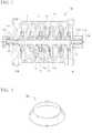
- FIG. 1 is a cross-sectional view illustrating an example of the centrifugal compressor in which the impeller (rotary machine component) 1 obtained according to the manufacturing method in this embodiment is used.
- the centrifugal compressor 10 compresses a process gas G which is a fluid.
- the centrifugal compressor 10 includes a casing 11 which forms the outer enclosure, a rotor 12 which is rotatably supported by the casing 11 and is rotated by a driving unit (not shown), and a plurality of impellers 1 mounted to the rotor 12, on the same axis as that of the rotor 12 in the casing 11.
- the driving unit that rotates the rotor 12 various units such as an electric motor or a turbine may be selected according to applications.
- a journal bearing 11a and a thrust bearing 11b are provided on each of both sides of the casing 11.
- a rotating shaft 12a of the rotor 12 is rotatably supported by the journal bearings 11a and the thrust bearings 11b.
- the casing 11 forms a plurality of operation chambers 11c which are continuous between the impellers 1 in the vicinities of the rotor 12 and the impellers 1, and on both sides thereof, a suction port 11d into which the process gas G flows and a discharge port 11e from which the process gas G flows out are provided to communicate with the operation chambers 11c.
- the impellers 1 which compress the process gas G through a rotary motion are configured to come into contact with the process gas G that flows in from the suction port 11d, an aqueous solution in which the process gas G is dissolved, and the like.
- the impellers 1 are configured so that a plurality of blades 1b are radially provided to be erected from a substantially discoid main body portion 1a and a shroud 1c is mounted to the tip end of the blade 1b.
- the process gas G which is the fluid to be compressed is able to flow to the inside of a diameter direction and in the axial direction and be discharged toward the outside in the diameter direction.
- an impeller material that forms the impeller 1 generally, a high-strength metal material such as a stainless steel is selected because a high load is exerted during compression of the process gas G.
- a high-strength metal material such as a stainless steel is selected because a high load is exerted during compression of the process gas G.
- a metal material which has both strength and corrosion resistance such as a duplex stainless steel.
- the duplex stainless steel used in this embodiment for example, there are materials corresponding to SUS329J1, SUS329J3L, and SUS329J4L.
- the impeller 1 of this embodiment is obtained by performing at least machining and a welding process as necessary on a material for a rotary machine component obtained in a manufacturing method as described later, or according to a method of manufacturing a rotary machine component described later.
- the method of manufacturing a material (see reference numeral A of FIG. 4 ) for a rotary machine component of this embodiment is a method of performing at least a solution treatment on a material made of a duplex stainless steel.
- the solution treatment is a method of heating the material at a temperature in a range of 950 to 1100°C and thereafter cooling the resultant to 700°C at an average cooling rate of 20°C/min or higher.
- the material made of the duplex stainless steel used in the manufacturing method of this embodiment is not particularly limited, and it is preferable to use a material made of materials corresponding to SUS329J1, SUS329J3L, and SUS329J4L as described above in terms of strength and corrosion resistance.
- the manufacturing method of this embodiment first, from an ingot made of the metal material, for example, a bar-like material called a bloom or a cylindrical material of which the thickness is set to a prescribed range as described later is formed.
- a bar-like material called a bloom or a cylindrical material of which the thickness is set to a prescribed range as described later is formed.
- various heat treatments as described as follows on the material, mechanical properties thereof are improved.
- the solution treatment described in this embodiment is a treatment of performing rapid cooling after performing high-temperature heating at a temperature unique to an alloy so as to cause an alloy element that is typically precipitated at a low temperature to be in a state of being dissolved in a basic metal element as a solid component, thereby improving mechanical properties of the alloy.
- the solution treatment is also called a solid-solution treatment or a quenching process.
- a temperature for the high-temperature heating in the solution treatment is generally in a range of 950 to 1100°C, and it is considered that a temperature of about 1050°C is more appropriate.
- a temperature for the high-temperature heating in the solution treatment is generally in a range of 950 to 1100°C, and it is considered that a temperature of about 1050°C is more appropriate.
- the manufacturing method of this embodiment by performing the solution treatment by heating the material to the temperature, precipitation of an embrittled phase in the material due to 475°C-embrittlement, ⁇ -embrittlement, or the like is suppressed, and thus a material for a rotary machine component having high toughness may be manufactured.
- the heating temperature in the solution treatment is out of the temperature range, there is a possibility of the quenching effect as described above being less likely to be obtained.
- the average cooling rate when the material subjected to the high-temperature heating to the temperature is cooled to 700°C is preferably equal to or greater than 20°C/min, and more preferably equal to or greater than 30°C/min.
- an annealing process is performed at a temperature in a range of 530 to 570°C.
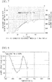
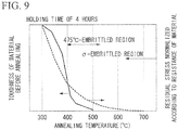
- the inventors intensively examined the annealing process in a manufacturing process of the material for a rotary machine component. As a result, as shown in the graph of FIG. 3 , it was found that by causing the temperature in the annealing process to be in a range of 530 to 570°C, high material toughness may be ensured and residual stress is sufficiently reduced.
- the toughness of the material is increased.
- residual stress is not reduced, and there is a possibility of a material having low strength properties being manufactured.
- the temperature of the annealing process is higher than 570°C, although the residual stress in the material is reduced, toughness is also reduced. Therefore, there is a possibility of cracking and the like being likely to occur during the manufacturing process or during operation.
- the temperature in the annealing process is about 550°C because the above effect is more stably obtained.
- a time taken to perform the annealing process under the temperature condition is preferably in a range of 1 to 12 hours, and more preferably, in a range of 4 to 8 hours.
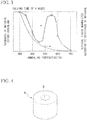
- the material made of the metal material is a discoid material and the thickness thereof is smaller than or equal to 300 mm (see a material A for a rotary machine component in FIG. 4 ).
- the rotary machine component used in a rotary machine such as the impeller for the centrifugal compressor described in this embodiment typically has a thickness of smaller than or equal to about 300 mm in the rotating shaft direction.
- the solution treatment having the above conditions is performed. Therefore, the solution (quenching) effects described above are more easily obtained. Accordingly, the material A for a rotary machine component in which precipitation of an embrittled phase is suppressed and of which the toughness is excellent and which is able to configure an impeller (rotary machine component) with a large thickness and a large diameter may be manufactured.
- the average cooling rate during the solution treatment is specified to a rate at which the precipitation of an embrittled phase is effectively prevented.
- the solution treatment having the above conditions is performed on the discoid material A having the above dimensions and shapes after a through-hole (boss hole) B is formed therein in the thickness direction.
- a through-hole B in the discoid material A in advance
- the cooling rate is increased during the solution treatment. Therefore, an effect of suppressing the precipitation of an embrittled phase as described above is more stably obtained.
- two curves are shown for each of a case with the through-hole B and a case without a through-hole. This represents a case where a measurement position in the thickness direction of the material for a rotary machine component is changed.
- the method of manufacturing an impeller (see the impeller 1 in FIG. 1 and an impeller intermediate product 1A of FIG. 2 ) of this embodiment is a method of performing machining and a welding process as necessary after performing at least a solution treatment on a material made of a duplex stainless steel.
- the solution treatment is a method of heating the material to a temperature in a range of 950 to 1100°C and thereafter cooling the material to 700°C at an average cooling rate of 20°C/min or higher.
- the solution treatment in the method of manufacturing an impeller of this embodiment has the same conditions as those of the method of manufacturing a material for a rotary machine component described above.
- a method of performing the solution treatment on the material under the conditions described above, and thereafter appropriately performing predetermined working processes, for example, machining, plastic working, and a welding process thereon so as to form the impeller 1 is provided. Therefore, the impeller 1 which suppresses the precipitation of an embrittled phase in the material due to 475°C-embrittlement, ⁇ -embrittlement, or the like and has high toughness may be manufactured.
- the average cooling rate during the solution treatment is equal to or greater than 30°C/min.
- an annealing process be performed at a temperature in a range of 530 to 570°C which is the same condition as that of the method of manufacturing a material for a rotary machine component described above.
- a time taken to perform the annealing process at the temperature is in a range of 1 to 12 hours.
- the material is a discoid material and the thickness thereof is smaller than or equal to 300 mm, as in the method of manufacturing a material for a rotary machine component described above.
- a method of directly performing a forging process on a metal material into a discoid shape which is close to the shape of the impeller 1 from an ingot without performing cooling part way to cause the material to have dimensions in the thickness direction of 300 mm at the maximum, and thereafter performing a solution treatment and various working processes, thereby manufacturing the rotary machine component is provided. Therefore, it is possible to form the impeller shape without limitations on shapes in the diameter direction.
- the cooling rate and the temperature distribution do not vary during the solution treatment, and it is possible to manufacture the impeller (rotary machine component) 1 in which the precipitation of an embrittled phase is suppressed and excellent toughness is provided.
- an ultrasonic flaw detection test (UT: ultrasonic test) and a magnetic flaw detection test (MT: magnetic test) are performed on the impeller intermediate product 1A obtained by the method.
- UT ultrasonic test
- MT magnetic test
- gas flow-channel electric discharge machining and finish polishing are performed on the impeller intermediate product 1A
- outer periphery machining is performed on the resultant, thereby forming the impeller 1 as illustrated in FIG. 1 .
- a balance spin test is performed as a final test.
- the processes and the tests performed on the impeller intermediate product 1A well-known methods according to the related art may be employed.
- the impeller of the centrifugal compressor as described above is exemplified as the material for a rotary machine component and the rotary machine component, and the centrifugal compressor is described as the rotary machine.
- the present invention is not limited to this.
- the method of manufacturing a material for a rotary machine component and the method of manufacturing a rotary machine component according to the embodiment of the present invention it is possible to manufacture the material for a rotary machine component in which the precipitation of an embrittled phase is suppressed and high toughness is provided and the rotary machine component using the same.
- the annealing process is performed according to the manufacturing methods, it is possible to manufacture the material for a rotary machine component in which the residual stress of the material is reduced and high toughness is provided and the rotary machine component using the same.
- the rotary machine component and the impeller obtained according to the manufacturing methods are used. Therefore, corrosion or stress corrosion cracking that occurs due to corrosive components is suppressed, and thus the occurrence of cracking and the like during machine operation may be prevented.
- Example 1 first, materials corresponding to SUS329J1, SUS329J3L, and SUS329J4L (all are made by Daido Steel Co., Ltd.) were prepared as duplex stainless steels, and a forging process was performed on each of the ingots thereof, thereby manufacturing round bar-like blooms having a diameter of 300 mm.
- the blooms were first heated to a temperature of 1050°C as the solution treatment, and thereafter were water-cooled from 1050°C to 700°C at an average cooling rate of 31 °C/min that is equal to or greater than 30°C/min, thereby manufacturing samples of the material for a rotary machine component.
- Example 2 first, as in Example 1, materials corresponding to SUS329J1, SUS329J3L, and SUS329J4L (all are made by Daido Steel Co., Ltd.) were prepared as duplex stainless steels, and a forging process was performed on each of the ingots thereof, thereby manufacturing samples of the material for a rotary machine component which are made of discoid materials having a thickness of 300 mm.
- Example 3 first, materials corresponding to SUS329J4L (made by Daido Steel Co., Ltd.) were prepared as duplex stainless steels, and a forging process was performed on each of the ingots thereof, thereby manufacturing round bar-like blooms having a diameter of 300 mm.
- the blooms were first heated to a temperature of 1050°C as the solution treatment, and thereafter were water-cooled from 1050°C to 700°C at an average cooling rate of 31 °C/min that is equal to or greater than 30°C/min. Then, an annealing process for stress removal was performed by holding the blooms at a temperature of 550°C for 4 hours, thereby manufacturing samples of the material for a rotary machine component.
- Example 4 first, materials corresponding to SUS329J4L (made by Daido Steel Co., Ltd.) were prepared as duplex stainless steels, and a forging process was performed on each of the ingots thereof, thereby manufacturing discoid materials having a thickness of 300 mm.
- the blooms were first heated to a temperature of 1050°C as the solution treatment, and thereafter were water-cooled from 1050°C to 700°C at an average cooling rate of 31 °C/min that is equal to or greater than 30°C/min. Then, rough working was performed by various machining and welding processes, thereby forming impeller intermediate products as illustrated in FIG. 2 .
- an annealing process for stress removal was performed by holding the impeller intermediate products at a temperature of 550°C for 4 hours, thereby manufacturing impellers (rotary machine components).
- Comparative Examples 1 to 4 first, as in each of Examples, materials corresponding to SUS329J4L were prepared as duplex stainless steels, and a forging process was performed on each of the ingots thereof, thereby manufacturing round bar-like blooms having a diameter of 300 mm.
- the blooms were first heated to a temperature of 1050°C as the solution treatment, and thereafter were water-cooled from 1050°C to 700°C at average cooling rates of 20°C/min, 25°C/min, 10°C/min, and 15°C/min, respectively, thereby manufacturing samples of the material for a rotary machine component of corresponding Comparative Examples.
- Residual stress was evaluated by analyzing stress remaining in the samples of each of Examples and Comparative Examples through X-ray diffraction using an X-ray apparatus.
- a ⁇ -phase area ratio was inspected by microstructure observation using an optical microscope and image analysis.
- a Charpy impact test as described as follows was performed. First, Charpy test specimens with V notches of 2 mm were collected from the samples. In addition, on the basis of the method according to JIS Z 2242, absorbed energy was measured by setting a test temperature to room temperature (23°C), and an impact value [J/cm 2 ] was obtained by dividing the absorbed energy by the cross-sectional area of the bottom of the notch.
- Example 1 the specification of the solution treatment of the present invention capable of reliably suppressing the precipitation of an embrittled phase was applied, and the material diameter was set to 300 mm which is the maximum material thickness that satisfies the specification. Accordingly, as shown in the graphs of FIGS. 6 and 7 , a material for a rotary machine component in which embrittled phases are reduced and toughness is high is obtained. It is apparent that using the material for a rotary machine component, a rotary machine component such as the impeller having excellent toughness may be manufactured.
- Example 2 a method of directly forging the material into a disk which is close to the shape of the rotary machine component such as the impeller without performing cooling on the ingot part way is provided. Therefore, it is apparent that a material which has excellent toughness and does not limit the outside diameter of the component is obtained.
- Example 3 since the annealing process was performed at an appropriate temperature in addition to the solution treatment, when the residual stress and the structure shape of the material before and after annealing were examined, residual stress due to compression of the outer surface or tension of the inner surface, which was present at a time point of the solution treatment, was reduced to substantially 0 (zero).
- Example 4 as in Example 3, since the annealing process was performed at an appropriate temperature in addition to the solution treatment, when the residual stress and the structure shape of the material before and after annealing were examined, residual stress due to compression of the outer surface or tension of the inner surface, which was present during welding, was reduced to substantially 0 (zero). In addition, it was confirmed that any of the precipitation of an embrittled phase after the annealing process, a 475°C-embrittled phase, and a ⁇ -embrittled phase was not present.
- Comparative Examples 1 to 4 are examples in which average cooling rates were changed in the solution treatment.
- Comparative Examples 1 and 2 are data of the example of the invention in which the average cooling rates were respectively 20°C/min and 25°C/min and thus the specification of the present invention was satisfied.
- Comparative Examples 3 and 4 are data of the example according to the related art in which the average cooling rates were respectively 10°C/min and 15°C/min.
- the material for a rotary machine component and the rotary machine component obtained by the method of manufacturing a material for a rotary machine component and the method of manufacturing a rotary machine component according to the present invention have both low residual stress and high toughness.
- the method of manufacturing a material for a rotary machine component and the method of manufacturing a rotary machine component according to the embodiments of the present invention it is possible to manufacture a material for a rotary machine component which suppresses the precipitation of an embrittled phase and has high toughness and a rotary machine component using the same.
- the annealing process is performed according to the manufacturing methods having the above configurations, it is possible to manufacture a material for a rotary machine component in which the residual stress of the material is reduced and high toughness is provided and a rotary machine component using the same.
Landscapes
- Chemical & Material Sciences (AREA)
- Engineering & Computer Science (AREA)
- Mechanical Engineering (AREA)
- Materials Engineering (AREA)
- Metallurgy (AREA)
- Organic Chemistry (AREA)
- Crystallography & Structural Chemistry (AREA)
- Physics & Mathematics (AREA)
- Thermal Sciences (AREA)
- General Engineering & Computer Science (AREA)
- Structures Of Non-Positive Displacement Pumps (AREA)
- Heat Treatment Of Articles (AREA)
- Turbine Rotor Nozzle Sealing (AREA)
Applications Claiming Priority (2)
| Application Number | Priority Date | Filing Date | Title |
|---|---|---|---|
| JP2010111204A JP5653653B2 (ja) | 2010-05-13 | 2010-05-13 | 回転機械部品用素材の製造方法及び回転機械部品の製造方法、回転機械部品用素材、回転機械部品並びに遠心圧縮機 |
| PCT/JP2011/060949 WO2011142423A1 (ja) | 2010-05-13 | 2011-05-12 | 回転機械部品用素材の製造方法及び回転機械部品の製造方法、回転機械部品用素材、回転機械部品並びに遠心圧縮機 |
Publications (3)
| Publication Number | Publication Date |
|---|---|
| EP2570504A1 EP2570504A1 (en) | 2013-03-20 |
| EP2570504A4 EP2570504A4 (en) | 2017-11-29 |
| EP2570504B1 true EP2570504B1 (en) | 2020-10-28 |
Family
ID=44914475
Family Applications (1)
| Application Number | Title | Priority Date | Filing Date |
|---|---|---|---|
| EP11780680.2A Not-in-force EP2570504B1 (en) | 2010-05-13 | 2011-05-12 | Method for manufacturing raw material for rotary machine component, method for manufacturing rotary machine component, rotary machine component and centrifugal compressor |
Country Status (5)
| Country | Link |
|---|---|
| US (1) | US9297389B2 (enExample) |
| EP (1) | EP2570504B1 (enExample) |
| JP (1) | JP5653653B2 (enExample) |
| CN (1) | CN102884208A (enExample) |
| WO (1) | WO2011142423A1 (enExample) |
Families Citing this family (5)
| Publication number | Priority date | Publication date | Assignee | Title |
|---|---|---|---|---|
| JP5090566B1 (ja) | 2011-10-12 | 2012-12-05 | イチカワ株式会社 | 湿紙搬送用ベルト |
| RU2014118917A (ru) * | 2011-11-16 | 2015-12-27 | Лист АГ | Способ присоединения функциональных элементов в валу |
| JP5738169B2 (ja) | 2011-12-22 | 2015-06-17 | 三菱重工業株式会社 | 機械部品の製造方法及びこの製造方法によって製造されたインペラを備えた回転機械 |
| ITCO20130067A1 (it) * | 2013-12-17 | 2015-06-18 | Nuovo Pignone Srl | Girante con elementi di protezione e compressore centrifugo |
| CN105526190B (zh) * | 2016-01-21 | 2018-09-28 | 盐城海纳汽车零部件有限公司 | 一种汽车发动机冷却水泵合金结构钢模锻轮毂 |
Family Cites Families (19)
| Publication number | Priority date | Publication date | Assignee | Title |
|---|---|---|---|---|
| JPS5853062B2 (ja) | 1974-04-28 | 1983-11-26 | ダイドウセイコウ カブシキガイシヤ | 遠心分離機の回転体等に適したフエライト−オ−ステナイト系ステンレス鋼 |
| JPS6053737B2 (ja) * | 1978-10-20 | 1985-11-27 | 株式会社日立製作所 | 水車ランナ用ステンレス鋳鋼 |
| JPS56108859A (en) * | 1980-01-31 | 1981-08-28 | Kubota Ltd | High strength stainless cast steel |
| JPS5914099B2 (ja) | 1980-04-04 | 1984-04-03 | 日本冶金工業株式会社 | 熱間加工性および耐局部腐食性に優れる二相ステンレス鋼 |
| JPH0235389B2 (ja) | 1981-09-24 | 1990-08-09 | Sony Corp | Deisuku*pureeyanohayaokurisochi |
| JPS5914099A (ja) | 1982-07-15 | 1984-01-24 | 松下電工株式会社 | 遠隔監視制御装置 |
| JPS62222020A (ja) * | 1986-03-24 | 1987-09-30 | Mitsubishi Heavy Ind Ltd | 2相ステンレス鋼構造物の残留応力低減方法 |
| JPH01142019A (ja) * | 1987-11-27 | 1989-06-02 | Kubota Ltd | 製紙用サクションロール胴部材の製造方法 |
| JPH01165750A (ja) * | 1987-12-23 | 1989-06-29 | Kawasaki Steel Corp | 高耐食性二相ステンレス鋳鋼 |
| JPH03122256A (ja) * | 1989-10-06 | 1991-05-24 | Hitachi Metals Ltd | 鋳造性に優れた高耐食性高強度二相組織ステンレス鋳鋼 |
| JP3227734B2 (ja) | 1991-09-30 | 2001-11-12 | 住友金属工業株式会社 | 高耐食二相ステンレス鋼とその製造方法 |
| JP3270498B2 (ja) * | 1991-11-06 | 2002-04-02 | 株式会社クボタ | 耐割れ性及び耐食性にすぐれる二相ステンレス鋼 |
| JP2790749B2 (ja) * | 1992-03-27 | 1998-08-27 | 株式会社クボタ | ドリル及びバイト加工性にすぐれる二相ステンレス鋼 |
| JPH1142019A (ja) * | 1993-04-05 | 1999-02-16 | Hiroshi Ise | 開閉覆付通気物質植保湿鉢 |
| JPH07292445A (ja) * | 1994-04-22 | 1995-11-07 | Japan Steel Works Ltd:The | 二相ステンレスクラッド鋼およびその製造方法ならびに溶接方法 |
| CN1201028C (zh) * | 2001-04-27 | 2005-05-11 | 浦项产业科学研究院 | 具有优越热加工性能的高锰二联不锈钢及其制造方法 |
| JP2003171743A (ja) * | 2001-12-06 | 2003-06-20 | Aichi Steel Works Ltd | 強度、靭性、耐海水性の優れた二相ステンレス鋼及びその製造方法 |
| JP4026472B2 (ja) | 2002-10-30 | 2007-12-26 | 株式会社ジェイテクト | 軸受部品の製造方法 |
| JP2004167595A (ja) * | 2002-11-22 | 2004-06-17 | Hirotoshi Baba | インペラおよびその機械加工方法 |
-
2010
- 2010-05-13 JP JP2010111204A patent/JP5653653B2/ja active Active
-
2011
- 2011-05-12 WO PCT/JP2011/060949 patent/WO2011142423A1/ja not_active Ceased
- 2011-05-12 CN CN201180023173XA patent/CN102884208A/zh active Pending
- 2011-05-12 US US13/697,111 patent/US9297389B2/en active Active
- 2011-05-12 EP EP11780680.2A patent/EP2570504B1/en not_active Not-in-force
Non-Patent Citations (1)
| Title |
|---|
| None * |
Also Published As
| Publication number | Publication date |
|---|---|
| JP5653653B2 (ja) | 2015-01-14 |
| US9297389B2 (en) | 2016-03-29 |
| EP2570504A4 (en) | 2017-11-29 |
| JP2011236491A (ja) | 2011-11-24 |
| CN102884208A (zh) | 2013-01-16 |
| US20130058773A1 (en) | 2013-03-07 |
| EP2570504A1 (en) | 2013-03-20 |
| WO2011142423A1 (ja) | 2011-11-17 |
Similar Documents
| Publication | Publication Date | Title |
|---|---|---|
| EP2570504B1 (en) | Method for manufacturing raw material for rotary machine component, method for manufacturing rotary machine component, rotary machine component and centrifugal compressor | |
| EP2455496B1 (en) | Precipitation hardening martensitic stainless steel and steam turbine component made thereof | |
| CN105745338B (zh) | 使用马氏体不锈钢的机构零件的制造方法和旋转装置、滚动轴承、以及滚动轴承单元 | |
| DK1917375T3 (en) | Stållegering og værktøjer eller komponenter fremstillet af stållegeringen | |
| JP7185551B2 (ja) | 磁気結合ポンプ用の缶および製造方法 | |
| US9574256B2 (en) | Steel for cold forging/nitriding, steel material for cold forging/nitriding, and cold-forged/nitrided component | |
| Mokaberi et al. | Fatigue fracture analysis of gas turbine compressor blades | |
| CN104451086B (zh) | 蒸汽涡轮用转子的制造方法 | |
| EP2334837A2 (en) | Solution heat treatment and overage heat treatment for titanium components | |
| KR20070006595A (ko) | 증기터빈용 배관과 그 제조법 및 그것을 이용한 증기터빈용주증기 배관과 재열 배관 및 증기터빈 발전플랜트 | |
| CN109880991B (zh) | 一种高防腐耐磨转炉一次除尘风机叶轮的热处理生产工艺 | |
| CN100510140C (zh) | 油井用马氏体系不锈钢管 | |
| HK1044355A1 (zh) | 具有改良切削性的抗點蝕雙相不銹鋼合金 | |
| EP3327159B1 (en) | Nickel base casting alloy, casting, and method for manufacturing an impeller of a rotary machine | |
| Ul‐Hamid et al. | Failure analysis of an impeller blade | |
| JP2020026744A (ja) | 動翼の製造方法 | |
| JP7488788B2 (ja) | 混練ロータ、混練機、ゴム材料の混練方法および混練ロータの製造方法 | |
| US20150132144A1 (en) | Precipitation hardening martensitic stainless steel, turbine component formed of said martensitic stainless steel, and turbine including said turbine component | |
| TW202246543A (zh) | 抗腐蝕孔蝕麻田散鐵不鏽鋼及其製作方法 | |
| US20230072974A1 (en) | Method of manufacturing cast iron components for industrial equipment | |
| JP5745092B2 (ja) | ターボ機械ロータ用の平軸受、および平軸受を有するターボ機械 | |
| EP4660336A1 (en) | Hydrogen-resistant material and hydrogen-resistant structural component | |
| Shao et al. | Failure analysis and service life prediction of condensate oil pump impellers in atmospheric-vacuum distillation units | |
| Seikh et al. | Effect of Molybdenum Content on the Corrosion and Microstructure of Low-Ni, Co-Free Maraging Steels. Metals 2021, 11, 852 | |
| Zhiritskii et al. | Design and Strength Calculation of Components in Steam and Gas Turbines |
Legal Events
| Date | Code | Title | Description |
|---|---|---|---|
| PUAI | Public reference made under article 153(3) epc to a published international application that has entered the european phase |
Free format text: ORIGINAL CODE: 0009012 |
|
| 17P | Request for examination filed |
Effective date: 20121109 |
|
| AK | Designated contracting states |
Kind code of ref document: A1 Designated state(s): AL AT BE BG CH CY CZ DE DK EE ES FI FR GB GR HR HU IE IS IT LI LT LU LV MC MK MT NL NO PL PT RO RS SE SI SK SM TR |
|
| DAX | Request for extension of the european patent (deleted) | ||
| RAP1 | Party data changed (applicant data changed or rights of an application transferred) |
Owner name: MITSUBISHI HEAVY INDUSTRIES COMPRESSOR CORPORATION |
|
| RA4 | Supplementary search report drawn up and despatched (corrected) |
Effective date: 20171027 |
|
| RIC1 | Information provided on ipc code assigned before grant |
Ipc: F04D 29/02 20060101ALI20171023BHEP Ipc: C21D 9/00 20060101AFI20171023BHEP Ipc: C21D 6/00 20060101ALI20171023BHEP Ipc: F04D 29/28 20060101ALI20171023BHEP Ipc: F04D 29/66 20060101ALI20171023BHEP Ipc: C22C 38/00 20060101ALI20171023BHEP |
|
| STAA | Information on the status of an ep patent application or granted ep patent |
Free format text: STATUS: EXAMINATION IS IN PROGRESS |
|
| 17Q | First examination report despatched |
Effective date: 20181102 |
|
| RIC1 | Information provided on ipc code assigned before grant |
Ipc: F04D 29/02 20060101ALI20200320BHEP Ipc: F04D 29/66 20060101ALI20200320BHEP Ipc: C21D 9/00 20060101AFI20200320BHEP Ipc: C21D 6/00 20060101ALI20200320BHEP Ipc: C22C 38/00 20060101ALI20200320BHEP Ipc: C21D 6/02 20060101ALI20200320BHEP Ipc: F04D 29/28 20060101ALI20200320BHEP |
|
| GRAP | Despatch of communication of intention to grant a patent |
Free format text: ORIGINAL CODE: EPIDOSNIGR1 |
|
| STAA | Information on the status of an ep patent application or granted ep patent |
Free format text: STATUS: GRANT OF PATENT IS INTENDED |
|
| INTG | Intention to grant announced |
Effective date: 20200527 |
|
| GRAS | Grant fee paid |
Free format text: ORIGINAL CODE: EPIDOSNIGR3 |
|
| GRAA | (expected) grant |
Free format text: ORIGINAL CODE: 0009210 |
|
| STAA | Information on the status of an ep patent application or granted ep patent |
Free format text: STATUS: THE PATENT HAS BEEN GRANTED |
|
| AK | Designated contracting states |
Kind code of ref document: B1 Designated state(s): AL AT BE BG CH CY CZ DE DK EE ES FI FR GB GR HR HU IE IS IT LI LT LU LV MC MK MT NL NO PL PT RO RS SE SI SK SM TR |
|
| REG | Reference to a national code |
Ref country code: GB Ref legal event code: FG4D |
|
| REG | Reference to a national code |
Ref country code: CH Ref legal event code: EP |
|
| REG | Reference to a national code |
Ref country code: DE Ref legal event code: R096 Ref document number: 602011069102 Country of ref document: DE |
|
| REG | Reference to a national code |
Ref country code: AT Ref legal event code: REF Ref document number: 1328288 Country of ref document: AT Kind code of ref document: T Effective date: 20201115 |
|
| REG | Reference to a national code |
Ref country code: IE Ref legal event code: FG4D |
|
| REG | Reference to a national code |
Ref country code: AT Ref legal event code: MK05 Ref document number: 1328288 Country of ref document: AT Kind code of ref document: T Effective date: 20201028 |
|
| REG | Reference to a national code |
Ref country code: NL Ref legal event code: MP Effective date: 20201028 |
|
| PG25 | Lapsed in a contracting state [announced via postgrant information from national office to epo] |
Ref country code: GR Free format text: LAPSE BECAUSE OF FAILURE TO SUBMIT A TRANSLATION OF THE DESCRIPTION OR TO PAY THE FEE WITHIN THE PRESCRIBED TIME-LIMIT Effective date: 20210129 Ref country code: FI Free format text: LAPSE BECAUSE OF FAILURE TO SUBMIT A TRANSLATION OF THE DESCRIPTION OR TO PAY THE FEE WITHIN THE PRESCRIBED TIME-LIMIT Effective date: 20201028 Ref country code: RS Free format text: LAPSE BECAUSE OF FAILURE TO SUBMIT A TRANSLATION OF THE DESCRIPTION OR TO PAY THE FEE WITHIN THE PRESCRIBED TIME-LIMIT Effective date: 20201028 Ref country code: NO Free format text: LAPSE BECAUSE OF FAILURE TO SUBMIT A TRANSLATION OF THE DESCRIPTION OR TO PAY THE FEE WITHIN THE PRESCRIBED TIME-LIMIT Effective date: 20210128 Ref country code: PT Free format text: LAPSE BECAUSE OF FAILURE TO SUBMIT A TRANSLATION OF THE DESCRIPTION OR TO PAY THE FEE WITHIN THE PRESCRIBED TIME-LIMIT Effective date: 20210301 Ref country code: NL Free format text: LAPSE BECAUSE OF FAILURE TO SUBMIT A TRANSLATION OF THE DESCRIPTION OR TO PAY THE FEE WITHIN THE PRESCRIBED TIME-LIMIT Effective date: 20201028 |
|
| REG | Reference to a national code |
Ref country code: LT Ref legal event code: MG4D |
|
| PG25 | Lapsed in a contracting state [announced via postgrant information from national office to epo] |
Ref country code: AT Free format text: LAPSE BECAUSE OF FAILURE TO SUBMIT A TRANSLATION OF THE DESCRIPTION OR TO PAY THE FEE WITHIN THE PRESCRIBED TIME-LIMIT Effective date: 20201028 Ref country code: BG Free format text: LAPSE BECAUSE OF FAILURE TO SUBMIT A TRANSLATION OF THE DESCRIPTION OR TO PAY THE FEE WITHIN THE PRESCRIBED TIME-LIMIT Effective date: 20210128 Ref country code: IS Free format text: LAPSE BECAUSE OF FAILURE TO SUBMIT A TRANSLATION OF THE DESCRIPTION OR TO PAY THE FEE WITHIN THE PRESCRIBED TIME-LIMIT Effective date: 20210228 Ref country code: ES Free format text: LAPSE BECAUSE OF FAILURE TO SUBMIT A TRANSLATION OF THE DESCRIPTION OR TO PAY THE FEE WITHIN THE PRESCRIBED TIME-LIMIT Effective date: 20201028 Ref country code: LV Free format text: LAPSE BECAUSE OF FAILURE TO SUBMIT A TRANSLATION OF THE DESCRIPTION OR TO PAY THE FEE WITHIN THE PRESCRIBED TIME-LIMIT Effective date: 20201028 Ref country code: SE Free format text: LAPSE BECAUSE OF FAILURE TO SUBMIT A TRANSLATION OF THE DESCRIPTION OR TO PAY THE FEE WITHIN THE PRESCRIBED TIME-LIMIT Effective date: 20201028 Ref country code: PL Free format text: LAPSE BECAUSE OF FAILURE TO SUBMIT A TRANSLATION OF THE DESCRIPTION OR TO PAY THE FEE WITHIN THE PRESCRIBED TIME-LIMIT Effective date: 20201028 |
|
| PG25 | Lapsed in a contracting state [announced via postgrant information from national office to epo] |
Ref country code: HR Free format text: LAPSE BECAUSE OF FAILURE TO SUBMIT A TRANSLATION OF THE DESCRIPTION OR TO PAY THE FEE WITHIN THE PRESCRIBED TIME-LIMIT Effective date: 20201028 |
|
| REG | Reference to a national code |
Ref country code: DE Ref legal event code: R097 Ref document number: 602011069102 Country of ref document: DE |
|
| PG25 | Lapsed in a contracting state [announced via postgrant information from national office to epo] |
Ref country code: SM Free format text: LAPSE BECAUSE OF FAILURE TO SUBMIT A TRANSLATION OF THE DESCRIPTION OR TO PAY THE FEE WITHIN THE PRESCRIBED TIME-LIMIT Effective date: 20201028 Ref country code: CZ Free format text: LAPSE BECAUSE OF FAILURE TO SUBMIT A TRANSLATION OF THE DESCRIPTION OR TO PAY THE FEE WITHIN THE PRESCRIBED TIME-LIMIT Effective date: 20201028 Ref country code: EE Free format text: LAPSE BECAUSE OF FAILURE TO SUBMIT A TRANSLATION OF THE DESCRIPTION OR TO PAY THE FEE WITHIN THE PRESCRIBED TIME-LIMIT Effective date: 20201028 Ref country code: SK Free format text: LAPSE BECAUSE OF FAILURE TO SUBMIT A TRANSLATION OF THE DESCRIPTION OR TO PAY THE FEE WITHIN THE PRESCRIBED TIME-LIMIT Effective date: 20201028 Ref country code: RO Free format text: LAPSE BECAUSE OF FAILURE TO SUBMIT A TRANSLATION OF THE DESCRIPTION OR TO PAY THE FEE WITHIN THE PRESCRIBED TIME-LIMIT Effective date: 20201028 Ref country code: LT Free format text: LAPSE BECAUSE OF FAILURE TO SUBMIT A TRANSLATION OF THE DESCRIPTION OR TO PAY THE FEE WITHIN THE PRESCRIBED TIME-LIMIT Effective date: 20201028 |
|
| PG25 | Lapsed in a contracting state [announced via postgrant information from national office to epo] |
Ref country code: DK Free format text: LAPSE BECAUSE OF FAILURE TO SUBMIT A TRANSLATION OF THE DESCRIPTION OR TO PAY THE FEE WITHIN THE PRESCRIBED TIME-LIMIT Effective date: 20201028 |
|
| PLBE | No opposition filed within time limit |
Free format text: ORIGINAL CODE: 0009261 |
|
| STAA | Information on the status of an ep patent application or granted ep patent |
Free format text: STATUS: NO OPPOSITION FILED WITHIN TIME LIMIT |
|
| 26N | No opposition filed |
Effective date: 20210729 |
|
| PG25 | Lapsed in a contracting state [announced via postgrant information from national office to epo] |
Ref country code: AL Free format text: LAPSE BECAUSE OF FAILURE TO SUBMIT A TRANSLATION OF THE DESCRIPTION OR TO PAY THE FEE WITHIN THE PRESCRIBED TIME-LIMIT Effective date: 20201028 |
|
| PG25 | Lapsed in a contracting state [announced via postgrant information from national office to epo] |
Ref country code: SI Free format text: LAPSE BECAUSE OF FAILURE TO SUBMIT A TRANSLATION OF THE DESCRIPTION OR TO PAY THE FEE WITHIN THE PRESCRIBED TIME-LIMIT Effective date: 20201028 |
|
| REG | Reference to a national code |
Ref country code: CH Ref legal event code: PL |
|
| GBPC | Gb: european patent ceased through non-payment of renewal fee |
Effective date: 20210512 |
|
| PG25 | Lapsed in a contracting state [announced via postgrant information from national office to epo] |
Ref country code: LI Free format text: LAPSE BECAUSE OF NON-PAYMENT OF DUE FEES Effective date: 20210531 Ref country code: MC Free format text: LAPSE BECAUSE OF FAILURE TO SUBMIT A TRANSLATION OF THE DESCRIPTION OR TO PAY THE FEE WITHIN THE PRESCRIBED TIME-LIMIT Effective date: 20201028 Ref country code: LU Free format text: LAPSE BECAUSE OF NON-PAYMENT OF DUE FEES Effective date: 20210512 Ref country code: CH Free format text: LAPSE BECAUSE OF NON-PAYMENT OF DUE FEES Effective date: 20210531 |
|
| REG | Reference to a national code |
Ref country code: BE Ref legal event code: MM Effective date: 20210531 |
|
| PG25 | Lapsed in a contracting state [announced via postgrant information from national office to epo] |
Ref country code: IE Free format text: LAPSE BECAUSE OF NON-PAYMENT OF DUE FEES Effective date: 20210512 Ref country code: GB Free format text: LAPSE BECAUSE OF NON-PAYMENT OF DUE FEES Effective date: 20210512 |
|
| PG25 | Lapsed in a contracting state [announced via postgrant information from national office to epo] |
Ref country code: IS Free format text: LAPSE BECAUSE OF FAILURE TO SUBMIT A TRANSLATION OF THE DESCRIPTION OR TO PAY THE FEE WITHIN THE PRESCRIBED TIME-LIMIT Effective date: 20210228 Ref country code: FR Free format text: LAPSE BECAUSE OF NON-PAYMENT OF DUE FEES Effective date: 20210531 |
|
| PG25 | Lapsed in a contracting state [announced via postgrant information from national office to epo] |
Ref country code: BE Free format text: LAPSE BECAUSE OF NON-PAYMENT OF DUE FEES Effective date: 20210531 |
|
| PG25 | Lapsed in a contracting state [announced via postgrant information from national office to epo] |
Ref country code: HU Free format text: LAPSE BECAUSE OF FAILURE TO SUBMIT A TRANSLATION OF THE DESCRIPTION OR TO PAY THE FEE WITHIN THE PRESCRIBED TIME-LIMIT; INVALID AB INITIO Effective date: 20110512 Ref country code: CY Free format text: LAPSE BECAUSE OF FAILURE TO SUBMIT A TRANSLATION OF THE DESCRIPTION OR TO PAY THE FEE WITHIN THE PRESCRIBED TIME-LIMIT Effective date: 20201028 |
|
| PG25 | Lapsed in a contracting state [announced via postgrant information from national office to epo] |
Ref country code: MK Free format text: LAPSE BECAUSE OF FAILURE TO SUBMIT A TRANSLATION OF THE DESCRIPTION OR TO PAY THE FEE WITHIN THE PRESCRIBED TIME-LIMIT Effective date: 20201028 |
|
| PG25 | Lapsed in a contracting state [announced via postgrant information from national office to epo] |
Ref country code: TR Free format text: LAPSE BECAUSE OF FAILURE TO SUBMIT A TRANSLATION OF THE DESCRIPTION OR TO PAY THE FEE WITHIN THE PRESCRIBED TIME-LIMIT Effective date: 20201028 |
|
| PGFP | Annual fee paid to national office [announced via postgrant information from national office to epo] |
Ref country code: DE Payment date: 20240328 Year of fee payment: 14 |
|
| PGFP | Annual fee paid to national office [announced via postgrant information from national office to epo] |
Ref country code: IT Payment date: 20240411 Year of fee payment: 14 |
|
| PG25 | Lapsed in a contracting state [announced via postgrant information from national office to epo] |
Ref country code: MT Free format text: LAPSE BECAUSE OF FAILURE TO SUBMIT A TRANSLATION OF THE DESCRIPTION OR TO PAY THE FEE WITHIN THE PRESCRIBED TIME-LIMIT Effective date: 20201028 |
|
| REG | Reference to a national code |
Ref country code: DE Ref legal event code: R119 Ref document number: 602011069102 Country of ref document: DE |
|
| PG25 | Lapsed in a contracting state [announced via postgrant information from national office to epo] |
Ref country code: DE Free format text: LAPSE BECAUSE OF NON-PAYMENT OF DUE FEES Effective date: 20251202 |
|
| PG25 | Lapsed in a contracting state [announced via postgrant information from national office to epo] |
Ref country code: IT Free format text: LAPSE BECAUSE OF NON-PAYMENT OF DUE FEES Effective date: 20250512 |