EP2570170A1 - Luftreinigeranordnung und Patronen, - Google Patents
Luftreinigeranordnung und Patronen, Download PDFInfo
- Publication number
- EP2570170A1 EP2570170A1 EP12178152.0A EP12178152A EP2570170A1 EP 2570170 A1 EP2570170 A1 EP 2570170A1 EP 12178152 A EP12178152 A EP 12178152A EP 2570170 A1 EP2570170 A1 EP 2570170A1
- Authority
- EP
- European Patent Office
- Prior art keywords
- end cap
- filter cartridge
- housing
- projection
- access cover
- Prior art date
- Legal status (The legal status is an assumption and is not a legal conclusion. Google has not performed a legal analysis and makes no representation as to the accuracy of the status listed.)
- Granted
Links
Images


Classifications
-
- B—PERFORMING OPERATIONS; TRANSPORTING
- B01—PHYSICAL OR CHEMICAL PROCESSES OR APPARATUS IN GENERAL
- B01D—SEPARATION
- B01D46/00—Filters or filtering processes specially modified for separating dispersed particles from gases or vapours
- B01D46/24—Particle separators, e.g. dust precipitators, using rigid hollow filter bodies
- B01D46/2403—Particle separators, e.g. dust precipitators, using rigid hollow filter bodies characterised by the physical shape or structure of the filtering element
- B01D46/2411—Filter cartridges
- B01D46/2414—End caps including additional functions or special forms
-
- B—PERFORMING OPERATIONS; TRANSPORTING
- B01—PHYSICAL OR CHEMICAL PROCESSES OR APPARATUS IN GENERAL
- B01D—SEPARATION
- B01D46/00—Filters or filtering processes specially modified for separating dispersed particles from gases or vapours
- B01D46/0084—Filters or filtering processes specially modified for separating dispersed particles from gases or vapours provided with safety means
- B01D46/009—Identification of filter type or position thereof, e.g. by transponders or bar codes
-
- B—PERFORMING OPERATIONS; TRANSPORTING
- B01—PHYSICAL OR CHEMICAL PROCESSES OR APPARATUS IN GENERAL
- B01D—SEPARATION
- B01D46/00—Filters or filtering processes specially modified for separating dispersed particles from gases or vapours
- B01D46/52—Particle separators, e.g. dust precipitators, using filters embodying folded corrugated or wound sheet material
-
- B—PERFORMING OPERATIONS; TRANSPORTING
- B01—PHYSICAL OR CHEMICAL PROCESSES OR APPARATUS IN GENERAL
- B01D—SEPARATION
- B01D46/00—Filters or filtering processes specially modified for separating dispersed particles from gases or vapours
- B01D46/56—Filters or filtering processes specially modified for separating dispersed particles from gases or vapours with multiple filtering elements, characterised by their mutual disposition
- B01D46/62—Filters or filtering processes specially modified for separating dispersed particles from gases or vapours with multiple filtering elements, characterised by their mutual disposition connected in series
- B01D46/64—Filters or filtering processes specially modified for separating dispersed particles from gases or vapours with multiple filtering elements, characterised by their mutual disposition connected in series arranged concentrically or coaxially
-
- F—MECHANICAL ENGINEERING; LIGHTING; HEATING; WEAPONS; BLASTING
- F02—COMBUSTION ENGINES; HOT-GAS OR COMBUSTION-PRODUCT ENGINE PLANTS
- F02M—SUPPLYING COMBUSTION ENGINES IN GENERAL WITH COMBUSTIBLE MIXTURES OR CONSTITUENTS THEREOF
- F02M35/00—Combustion-air cleaners, air intakes, intake silencers, or induction systems specially adapted for, or arranged on, internal-combustion engines
- F02M35/02—Air cleaners
- F02M35/024—Air cleaners using filters, e.g. moistened
- F02M35/02416—Fixing, mounting, supporting or arranging filter elements; Filter element cartridges
-
- F—MECHANICAL ENGINEERING; LIGHTING; HEATING; WEAPONS; BLASTING
- F02—COMBUSTION ENGINES; HOT-GAS OR COMBUSTION-PRODUCT ENGINE PLANTS
- F02M—SUPPLYING COMBUSTION ENGINES IN GENERAL WITH COMBUSTIBLE MIXTURES OR CONSTITUENTS THEREOF
- F02M35/00—Combustion-air cleaners, air intakes, intake silencers, or induction systems specially adapted for, or arranged on, internal-combustion engines
- F02M35/02—Air cleaners
- F02M35/024—Air cleaners using filters, e.g. moistened
- F02M35/02475—Air cleaners using filters, e.g. moistened characterised by the shape of the filter element
- F02M35/02483—Cylindrical, conical, oval, spherical or the like filter elements; wounded filter elements
-
- B—PERFORMING OPERATIONS; TRANSPORTING
- B01—PHYSICAL OR CHEMICAL PROCESSES OR APPARATUS IN GENERAL
- B01D—SEPARATION
- B01D2265/00—Casings, housings or mounting for filters specially adapted for separating dispersed particles from gases or vapours
- B01D2265/02—Non-permanent measures for connecting different parts of the filter
- B01D2265/021—Anti-rotational means
-
- B—PERFORMING OPERATIONS; TRANSPORTING
- B01—PHYSICAL OR CHEMICAL PROCESSES OR APPARATUS IN GENERAL
- B01D—SEPARATION
- B01D2265/00—Casings, housings or mounting for filters specially adapted for separating dispersed particles from gases or vapours
- B01D2265/02—Non-permanent measures for connecting different parts of the filter
- B01D2265/024—Mounting aids
- B01D2265/026—Mounting aids with means for avoiding false mounting
Definitions
- the present disclosure relates to air cleaners. It particularly concerns air cleaners in which the main filter cartridge includes an open end with an internally directed radial seal thereat, and a closed end.
- One member of a projection/receiver arrangement is positioned on the first end cap.
- Another member is included in a housing, for securely supporting the main filter cartridge.
- Air cleaners are generally used to filter combustion intake air for internal combustion engines of a variety of vehicles and other equipment such as: trucks; buses; off-road construction equipment; agricultural equipment; generator sets; etc.
- Such air cleaners generally include a housing, an air flow inlet and an air flow outlet.
- a removable and replaceable main filter cartridge is positioned in the housing.
- the housing includes a service or access cover, for selected access to the internally received filter cartridge, for servicing.
- the filter cartridge is typically serviced by being removed and either: being replaced with a factory new cartridge; being refurbished and being re-installed; or, by being replaced with a previously used, but refurbished, cartridge.
- an air cleaner arrangement which comprises an air cleaner housing and a serviceable air filter cartridge.
- the air cleaner housing includes an air flow inlet arrangement and an air flow outlet arrangement.
- the air cleaner housing defines an housing interior and comprises a housing body and an access cover.
- the serviceable air filter cartridge is operably positioned within the housing interior.
- the air filter cartridge comprises a media pack extending between first and second end caps.
- the media pack surrounds and defines an open filter interior.
- the first end cap is an open end cap having an air flow aperture therethrough.
- the second end cap is typically a closed end cap having and outer end surface.
- outer end surface in this context refers to a surface facing generally away from the first end cap.
- a housing seal arrangement is provided on the first end cap and is oriented for sealing to the air cleaner housing.
- the housing seal arrangement can comprise a radially directed seal.
- the housing seal is a radially inwardly directed seal.
- a projection/receiver arrangement including first and second members is provided.
- One (e.g., a second) member of the projection/receiver arrangement is positioned on the access cover. It typically comprises a serpentine ring member, and can either be a ring projection or a ring shaped receiver groove.
- the member of the projection/receiver arrangement which is positioned on the access cover, comprises a serpentine receiving groove.
- Another (i.e., first) member of the projection/receiver arrangement is positioned on the outer end surface of the end cap. It is engageable with the access cover, in a defined manner.
- first and second members of the projection/receiver arrangement are engaged to provide cantilevered support of the air filter cartridge at the second end.
- first and second members of the projection/receiver arrangement are also engaged in a non-rotatable manner.
- non-rotatable manner it is context, it is meant the engagement inhibits rotation of the filter cartridge with respect to the access cover (and thus the housing) once installation has occurred.
- the second member of the projection/receiver arrangement is a groove receiver on the access cover
- the first member of the projection/receiver arrangement is an axial ring projection on the filter cartridge
- the first member of the projection/receiver arrangement (i.e., the member on the filter cartridge) is a serpentine ring member comprising alternating convex and concave portions.
- the second member is a serpentine groove on the access cover.
- the assembly includes a housing including an air flow inlet arrangement and an air flow outlet arrangement; and, comprises a housing body and an access cover; and, a serviceable filter cartridge operably positioned within the housing.
- the access cover includes, in an example depicted, a serpentine receiving groove therein.
- the cartridge includes a projection which extends into the serpentine receiving groove of the access cover.
- An example filter cartridge which includes a projection on a closed end, that includes at least one arcuate section in which the at least one arcuate section is not a section of a curve corresponding to a circle extending around a center of the end cap. An example arrangement corresponding to this, is described.
- the reference numeral 1, Fig. 1 generally indicates an air cleaner assembly according to the present disclosure.
- the air cleaner assembly 1 includes a housing 2 having a housing body 3 and an access or service cover 4.
- the assembly 1 includes a removable and replaceable, i.e., serviceable, filter cartridge 5.
- the housing 1 (in particular the housing body 3) includes mounting pads 8 thereon, for securement to framework of a vehicle or other equipment on which the air cleaner assembly 1 is secured, for use.
- mounting pads 8 can be used, within the principles of the present disclosure.
- a mounting band arrangement can be used instead of mounting pads formed integrally with the housing body.
- the housing body 3 comprises a side wall 10 having a first open end 11 and opposite second end 12 with a first air flow passageway 13 thereat.
- the housing 2 further includes, in the example shown, second air flow passageway 15.
- air flow passageway 13 is an airflow outlet passageway defined by outlet tube 13a; and airflow passageway 15 is an inlet air flow passageway defined by inlet tube 15a. It is noted that for the example shown, both airflow passageways 13a, 15a are located in the housing body 3. In some alternate applications to the principles described herein, one of the airflow passageways, for example inlet air flow passageway 15, can be located in access cover 4.
- airflow passageways 13a, 15a are each a single aperture.
- one or more of the passageways 13a, 15a can be defined by multiple apertures.
- the air flow inlet 15 provides for passage of air to be filtered, into air cleaner 1.
- the particular air flow inlet 15 depicted, is positioned to direct that air through side wall 10.
- the air filter cartridge 5 is inserted into the housing body 3 through open end 11. Access cover 4 is then fit over the open end 11 and cartridge 5, to close the open end 11.
- the housing 2 includes a closure arrangement 20 comprising a plurality of latches 21. Access cover 4 is secured in place on the housing end 11 by the closure arrangement 20.
- closure arrangement 20 (comprising latches 21) is mounted on the access cover 4 for selected engagement with the housing body 3. It is noted that in some alternate applications of the techniques described herein, latches 21 can be positioned on the housing body 3 for engagement with the access cover 4.
- the cartridge 5 generally comprises a media pack 25 extending between first and second opposite end caps 26, 27.
- end cap 27 will be a closed end cap, i.e., it has no apertures therethrough, through which air can flow.
- End cap 26, however, will typically be an open end cap, including central open air flow aperture 29 therethrough and around which the media pack 25 extends.
- the media pack 25 can include media 25a selected from a variety of types of media.
- the media pack 25 may, for example, comprise pleated media, although alternatives are possible.
- the media pack 25 will be provided with one or more of inner and outer support liners for the media 25a.
- Such support liners can, for example, comprise plastic arrangements, expanded metal arrangements or porous metal arrangements.
- the media 25a surrounds and defines an open interior 30.
- the aperture 29, in the first end cap 26, is generally in air flow relationship with the open interior 30.
- air flow relationship in its context, and variants thereof, it is meant that the aperture 29 opens into the interior 30, and air can flow between the two without passage through the media pack 25.
- a secondary or safety filter cartridge can be applied and used with, in addition to the primary filter cartridge 5, a secondary or safety filter cartridge.
- the example depicted in the figures does not show a safety cartridge.
- a safety cartridge can be positioned internally of an interior 30. This would require the air, once though the media 25a, to pass through the safety cartridge before exiting the housing 2, through airflow exit 13.
- a typical media pack 25 can be provided in a variety of shapes, for example it can be cylindrical, or have a conical taper to it.
- the taper will be downwardly (inwardly) from end cap 26 toward end cap 27.
- the typical conical angle (taper inward) when used, would be at least about 0.5 degrees usually at least 1.0 degree and often within the range of 1.0 - 6.0°, including, although alternatives are possible.
- the particular air cleaner assembly 1 depicted is configured for "forward" flow.
- forward in this context, it is meant that air, during filtering, generally flows through media pack 25 from exterior into the open interior 30 (sometimes referred as out-to-in flow.)
- air to be filtered flows through inlet 15, into an annulus 35 ( Fig. 2 ) within housing 2 (and access cover 3) that extends around the filter cartridge 5.
- the air then passes through the media pack 25 into open interior 30.
- the air then passes from the cartridge 5 through open end 29, and leaves the air cleaner through inlet air flow outlet 13.
- the housing body 3 is secured to the equipment such as a truck, with which the air cleaner 1 is used, and the access cover 4 is separable from the main body 3, for service access to cartridge 5.
- cartridge 5 includes a housing seal arrangement 38 on end cap 26, sealed into a portion of the housing 2, when cartridge 5 is installed.
- the housing 2 (comprising body 3 and access cover 4) is configured for each of the two components to be molded from a plastic, for example a glass filled polypropylene.
- a plastic for example a glass filled polypropylene.
- the principles described herein are particularly adapted for plastic arrangements, however they can be utilized when one more of the components 3,4, or portions of the components 3,4 comprise sheet metal.
- FIG. 2 a side elevational view of air cleaner assembly 1 is depicted.
- air cleaner assembly 1 is shown with access cover 4 secured to housing body 3.
- a portion of air cleaner assembly 1 is depicted in cross-section, so that internal detail can be viewed.
- air flow annulus 35 around cartridge 5 is viewable.
- the example air flow annulus 35 extends completely radially around cartridge 5, for distribution of air to be filtered around the cartridge 5, during operation.
- cartridge 5 includes a housing seal arrangement 38 on end cap 26, sealing a portion to the housing 2 when cartridge 5 is installed.
- the radial seal portion 38a is generally oriented to form an inwardly directed radial seal against an outer surface of tube 39, when cartridge 5 is installed.
- Such inwardly directed radial seal arrangements are described, for example, in US 5,547,480 ; 6,652,614 ; WO 2007/022171 ; 6,039,778 ; and, 6,955,701 . It is noted that a variety of alternate housing seal arrangements locations and configurations can be used in the cartridge 5 and the housing 3 according to the present disclosure. Outwardly directed radial seals, for example, can be used, although still further alternatives are possible.
- the end cap 26 will be a molded-in-place end cap comprising a foamed polyurethane such as those described in US 6,955,701 . Such materials can be formed, during the molding process, to define radial seal portion 38a in aperture 29.
- the cartridge 5 is sufficiently long to project into the access or service cover 4.
- portion 5x of cartridge 5 extends beyond the housing body 3 into the access cover 4.
- this extension would be at least 30 mm and typically within the range of 40-75 mm, inclusive, of cartridge length between the end caps 26 and 27.
- the principles described herein, however, can be applied in arrangements in which a separation line (indicated at 40, Fig. 2 ), between the access cover 4 and the housing body 3 is located beyond end cap 27, in a direction away from end cap 26.
- the air filter cartridge 5 when installed, is secured at end cap 26 around tube 39, and is supported at this location.
- the cartridge 5 should be supported, or the air filter cartridge 5 will be cantilevered with respect to the housing tube.
- Support to the cartridge 5 from the housing 2 at end cap 27, which prevents undesirable levels of cantilevered movement will be referred to as “cantilevered” or “cantilever end” support, or by similar terms.
- cantilevered support is provided at end cap 27, by engagement between a portion of the access cover 4 and a portion of the end cap or cover 27, as discussed below.
- a projection/receiver arrangement is provided with one member on end cap 27 and another member on access cover 4, providing for an engagement in a manner which inhibits cantilevered motion of cartridge 5 at end cap 27.
- the media 25a can be seen as having opposite ends 25b, 25c; end 25b being adjacent end cap 27 and end 25c being adjacent end cap 26.
- Media 25a and thus the cartridge 5, is supported at end 25c by the insertion of tube 39 into end cap 26.
- end 25b, remote from end 25c is cantilevered.
- cantilevered motion and variants thereof, is meant to refer to movement (not rotational) that could occur at end 25b, remote from tube 39, if end cap 27 is not appropriately supported.
- the particular motion referenced, with respect to cantilevered motion is a vibrational movement, i.e., not a rotational movement. Cantilevered motion, then, would be up and down movement of media end 25b, or back and forth movement of media end 25b, or some combination thereof.
- cantilevered support is support of cartridge 5 against undesirable levels of cantilevered motion. That is, the effort is not necessarily to prevent any vibrational movement, but only to inhibit movement beyond some acceptable level.
- the engagement at end cap 26, for the example air cleaner assembly depicted, is a circular, inwardly directed, radial seal. Thus, it is radially symmetric, and subject to potential rotation of the cartridge 5 around tube 39.
- Support at end cap 27 through engagement between the end cap 27 and the access cover 4 also inhibits relative rotational motion of the cartridge 5, relative to access cover 4, once installed. Since the access cover 4 is secured in place on the body 3, this inhibits rotation of end cap 26 around tube 39, once cartridge 5 is installed.
- non-rotatable engagement An engagement between the access cover 4 and the cartridge 5 that inhibits undesirable levels of rotational movement of one relative the other will be referred to herein as "non-rotatable" engagement.
- non-rotatable engagement since the access cover 4 is generally non-rotatably secured in place in the housing body 3, by arrangement 20, a non-rotatable engagement between the access cover 4 and the cartridge 5 inhibits the cartridge 5 from rotating about tube 39 once installed.
- access cover 4 includes an ejection port 45 therein. Water and/or dust can be ejected through port 45, during operation. Typically, air cleaner 1 is installed with dust and water ejection port 45 angled downwardly.
- the access cover 4 includes no projection or shield, extending axially therefrom (toward end 12 of body 3) and spaced inwardly from side 4x which also surrounds the cartridge 5.
- the absence of such a shield facilitates flow of air around end 27 and direction of dust and water toward evacuation outlet 45. It also means the no portion of the media at 25 is covered up, from flow therearound.
- access cover 4 includes an outer rim 4x which engages body 3, when access over 4 is mounted.
- the rim section 4x, Fig. 2 is the only portion of the access cover 4, in the example shown, which surrounds an outer side portion of the media pack 25.
- FIG. 3 an end elevational view of air cleaner assembly 1 is depicted.
- the view is directed toward housing end 12 and outlet 13.
- pad arrangement 8 for securing the housing 2 to place on equipment is also viewable.
- Fig. 3 one can view through tube 13 into interior 30 of cartridge 5.
- end cap 27 comprises a closed end cap, having no aperture therethrough, and extending across end 25b of the media pack 25; an opposite end 25c of media pack 25 being embedded in end cap 26.
- end cap 27 will comprise a preformed piece, to which media pack 25 is potted with an adhesive or sealant material.
- end cap 27 will comprise a preformed plastic material, such as an ABS potted with a hard polyurethane.
- end cap 26 will be molded-in-place from a resin appropriate to form a soft, compressible, structure, i.e., the media pack 25 will be inserted into the material of end cap 26 as the material hardens and is molded to the designed shape. While this is not required, it will be typical for any applications of the present principles.
- End cap 27 in contrast, is typically molded first from a material appropriate to form a rigid plastic, part and is then attached to end 25b for example with a potting adhesive. Although alternatives are possible, this will be typical and convenient.
- Fig. 4 an end view of cartridge 5 is provided.
- the end view of cartridge 5 is taken directed toward end cap 27.
- the structural surface viewable in Fig. 4 is exterior surface 27x of end cap 27, Fig. 2 .
- FIG. 5 a cross-sectional view is taken along line 5-5, Fig. 4 .
- both exterior surface 27x and interior surface 27i are viewable in end piece 27.
- Fig. 5 is a fragmentary cross-sectional view. End 25b of media pack 25 is viewable in fragmentary view.
- end cap 27 includes an outer rim 51.
- the outer rim 51 fits around (circumscribes) the media pack 25.
- end piece 27 includes a rib 53.
- Rib 53 operates as a media standoff, during assembly. That is, when the media pack 25 is fit within end 51, the media pack 25 abuts rib 53 during potting.
- Projection 55 forms an inside of a containment ring for the media pack 25 and potting material (the outside containment provided by rim 51). That is, during assembly of cartridge 5, the media pack 25 is positioned with end 25b thereof oriented between rim 51 and inner projection 55. A potting material is positioned at this location, to secure end piece 27 in place on the media pack 25. Stand off rib 53 will ensure that the sealing or potting material can seal between end 27b of the media pack 25, and perimeter ring portion 58 of inner surface 27i.
- end surface 27x includes an outer ring section 65 in overlap with media pack 25 in cartridge 5.
- Outer surface 27x further includes an inner central, portion 66, surrounded by outer ring 65.
- the central portion 66, in the cartridge 5, Fig. 2 is not in axial overlap within media pack 25, but rather overlaps the interior region 30 that is surrounded by the media pack 25.
- region 65 and rim 51 can be viewed as having a circular orientation around center 27z of end cap 27.
- a projection/receiver arrangement is provided for engagement between the cartridge 5 and the access cover 4.
- the projection/receiver arrangement depicted provides for engagement between the cartridge end cap 27 and the access cover 4, in a manner that supports the cartridge 5 against undesirable levels of cantilevered motion at end cap 27; and, inhibits relative rotational motion between the cartridge 5 and the access cover 4 (and thus between the cartridge 5 and the outlet tube 39 in air cleaner assembly 1).
- the projection/receiver arrangement includes a projection member on a first one of cartridge 5 and access cover 4; and, receiver member on another one of the access cover 4 and cartridge 5.
- the projection/receiver arrangement includes a projection (first) member arrangement on the cartridge 5, and a receiver (second) member arrangement on the access cover 4; however, alternatives are possible.
- the central portion 66, of end cap outer surface 27x includes thereon projection arrangement 70.
- the projection arrangement 70 projects from a remainder of end cap 27, in a direction away from the end 256 of media pack 25; i.e., in a general direction away from opposite end cap 26.
- the distance of projection 70 indicated at dimension CJ, Fig. 5 is typically at least 10 mm, usually at least 15 and often within the range of 20 to 40 mm. In the example depicted, the dimension CJ is 25 mm.
- the direction of projection 70 is generally axial, i.e., in the direction corresponding to the general direction of central axis X, Fig. 2 and away from end cap 26.
- axial in this context, it is not meant that the projections of outer and inner surfaces 70o, 70i of projection 70 are necessarily precisely parallel to axis X. Indeed each can be angled from axis X somewhat.
- outer surface 70o slants inwardly, along a direction of extension from an adjacent region of end cap 27; and, inner surface 70i slants outwardly along its direction of extension from an adjacent region of end cap 27.
- This angle of slant inwardly of surface 70o is indicated at CK, and is generally within the range of 3-7°; inclusive.
- the corresponding angle of extension outwardly surface 70i is indicated at CM and typically within the range of 3-7°; inclusive. In the example depicted, Fig. 5 , CK and CM are each 5.6°.
- Angles to surfaces 70o, 70i of the type indicated, provide the projection 70 with an axially outermost tip 70t, which is narrowed somewhat relative to a base region 70b of projection 70.
- a somewhat narrow tip 70t facilitates insertion into a receiver arrangement, described below, on access cover 4.
- FIG. 5A a schematic, fragmentary, plan view of projection arrangement 70 taken in a general direction of arrow 80, Fig. 5 . It is noted that in Fig. 5A , the schematic depiction provides the general shape of projection 70 in plan view, and does not account for a slant to sides 70o, 70i.
- the particular projection arrangement 70 depicted comprises a continuous wall 84.
- continuous in this context, it is meant that there are no gaps in the wall 84 with respect to extension around the perimeter defined by the wall 84; i.e., around center 27z.
- the wall 84 is completely “closed.” By this it is meant that the wall 84 includes no apertures therethrough, in its continuous extension.
- the projection 70 is "solid" throughout; i.e. does not have a hollow interior between surfaces 70o, 70i. This will be typical and convenient.
- the projection arrangement 70 generally has a minimum largest external dimension thereacross, corresponding to dimension D 1 , Fig. 5A of at least 35 mm and often within the range of 40 to 100 mm. A reason for this is that it facilitates engagement with the access cover 4, in a typical preferred arrangement.
- the particular wall 84 depicted surrounds an open and recessed interior surface section 85.
- This section typically has a smallest internal dimension access shown at D 2 , of at least 15 mm typically at least 20 mm and often within the range of 30 to 90 mm.
- projection 70 is configured around center 27z such that the minimum largest dimension thereacross indicated at D 1 , can be measured in at least two directions at right angles to one another; i.e., D 1 indicated in Fig. 5a would also indicate a minimum largest dimension in a direction perpendicular to line D 1 .
- the configuration of the objection 70 is such that the smallest inside dimension thereacross, indicated at D 2 , is met in two directions, the first direction being for example as indicated at line D 2 , and a second dimension taken perpendicular to the first dimension.
- the projection 70 has a depth of extension from its tip 70t over a distance of at least 6 mm (and typically at least 12 mm) in which the thickness of projection 70 does not exceed 10 mm, but is typically at least 4 mm (discounting tapering at the very tip.) This would be for example a width between walls 70i, 70o, extending inwardly from tip 70t at least a depth of 25% and typically at least 35% of its extent of projection. Of course near the base 70b, Fig. 5 , projection 70 may thicken (widen) somewhat.
- serpentine outer surface 88 has a serpentine outer surface 88 and a serpentine inner surface 89, corresponding to surfaces 70o, 70i respectively.
- serpentine in connection with the outer surface 88, it is meant that extension around center 27z, outer surface 88 does not define a series of straight lines or even a circle, but rather a series of alternating inner and outer curves.
- serpentine surface 88 comprises a plurality of radially outwardly facing convex sections 88c, and a plurality of radially outwardly facing concave sections 88d alternating with one another.
- radially outwardly facing convex section 88c is meant to refer to a section of surface 88 which curves outwardly; and the reference to “radially outwardly facing concave sections 88d” is meant to refer to a section of surface 88 which curves inwardly.
- radially inwardly facing inner surface 89 is also serpentine, comprising a plurality of radially inwardly facing convex sections 89c and radially inwardly facing concave sections 89d, alternating with respect to one another, as the inner surface 89 extends around center 27z.
- each concave section 89d of inner surface 89 corresponds with, and aligns radially with, a convex section 88c of outer surface 88; and, each convex section 89c of inner surface 89 is aligned radially with concave section 89d of outer surface 88.
- wall 84 defines, in each of the outer surface 88 and inner surface 89, eight concave sections and eight convex sections. Further: (a) a curvature of each convex 88c section of surface 88 is the same as each other convex section 88c in surface 88, and, (b) a curvature of each concave section 88c is the same as each other concave 88d. The same is true for each cover section 89c and each concave section 89d. The result is a regular "petal" shape to projection 70.
- each outwardly projecting petal has the same shape as each other outwardly projecting petal.
- the center of each convex section 88c in the outer surface 88 can be seen to define a vertex of an octagonal shape, indicated at phantom lines at 95.
- each center point of each concave section 89c in surface 89 can be seen to define a center point in a side of an internally positioned octagon depicted in phantom lines at 96.
- the octagons 95, 96 are radially aligned, one spaced from the other.
- serpentine projection 70 comprises a plurality of outward convex petal sections and inward concave sections, providing for a serpentine extension of wall projection 70 around center 27c.
- each outwardly directed convex section 89c is such as to have a smaller radius of curvature than a hypothetical curvature of such a section if directed on, or positioned on, a circle centered on center 27z. This is apparent by referring to Fig. 4 and comparing the curvature of circle C1 to the curvature of outer convex sections 88c.
- FIGs. 6 and 7 Attention is now directed to Figs. 6 and 7 , in which portions of access cover 4 are viewable. It is noted that in Figs. 6 and 7 , access cover 4 is depicted without closure arrangement 20 thereon, for convenience.
- FIG. 6 the view of access cover 4 depicted is generally toward exterior surface 4y.
- Fig. 7 a cross-sectional view taken along line 7-7, Fig. 6 is viewable.
- access cover 4 generally includes end wall 100 and side wall 101; side wall 101 corresponding to side wall 4x, Fig. 2 .
- Side wall 101 includes open end 101a positioned and sized for engagement with housing body 3, Fig. 1 .
- Side wall 101 for the example shown, is sized to surround a portion of cartridge 5, to, during assembly.
- Central section 100 is a central, end, section of access cover 4 that includes water/dust ejector port 45 therein. In use, the port 45 would typically be provided with a valve member.
- access cover 4 includes an interior surface 4i with a central region 100i.
- Central region 100i includes thereon a second member 105 of a projection/receiver arrangement.
- the second member of the projection/receiver arrangement 105 is sized, configured and positioned for selective engagement with a first member of a projection/receiver arrangement, on cartridge 5.
- the cartridge 5 includes a projection 70 of a projection/receiver arrangement thereon. Therefore, the access cover 4 includes a receiver member 110 thereon, positioned for engagement with projection member 70.
- receiver member 110 defines a receiver groove 111 in cover interior surface 4i.
- the receiver groove 111 generally extends around a central axis Y on access cover 4. It is noted that for the particular example, groove 111 is not centered around line Y, but rather is eccentrically positioned relative thereto.
- FIG. 7A a fragmentary schematic, perspective, view of receiver groove 111 is depicted.
- the groove 111, Fig. 7A is depicted in a view corresponding to an enlarged portion of Fig. 1 .
- receiver groove 111 defined between an outer wall 112 and an inner wall 113.
- the example receiver groove 111 depicted is continuous.
- continuous in this context, it is meant for the particular example depicted, the groove 111 extends around a center 125, Fig. 7A , in a continuous uninterrupted path; i.e., the groove 111 does not includes any barriers or blockages therein, in its extension.
- Fig. 7B is a schematic plan view of groove 111.
- the schematic plan view of Fig. 7B does not show the tapering of the side walls, but otherwise shows the general shape.
- the particular receiver groove 111 is serpentine in shape, having convex sections 115 and concave sections 117, alternating with respect to one another.
- convex section in this context, is meant to refer to an outward bow or bend relative to center 125, and a “concave” section is meant to refer to an inward bend or projection toward center 125.
- an outwardly directed “concave” section could be characterized as an inwardly directed convex section.
- the curvature of convex sections 115 is generally selected, so as not to rest on a circle surrounding a center 125 of the receiver groove 111.
- the curvature of each convex section 115 is selected to have a narrower curvature, than a corresponding circle around 125.
- the particular serpentine receiver groove 111 depicted is defined by outer wall 112 and inner wall 113.
- Outer wall 112, then, has inner convex sections 112c and concave sections 112d; and, inner wall 113 has outer convex sections 113c and concave sections 113d.
- each of walls 112, 113 is, independently, continuous, closed and solid.
- the groove 111 has eight convex sections and eight concave sections.
- the groove 111 forms a octagonal or outwardly directed, petal shape, as previously discussed with respect to projection 70, Fig. 5A .
- Groove 111 is shaped to receive projection 70 projecting therein when cartridge 25 is installed in air cleaner 1, Fig. 2 .
- Figs. 6 and 7 example dimensions are indicated, for the assembly 1 depicted and described herein. Of course alternative dimensions are possible, and alternate applications that techniques described herein.
- the receiver groove of 111 will typically be at least 10 mm deep, usually at least 15 mm deep and often within the range of 20 - 40 mm deep, although alternatives are possible in some applications of the techniques described herein. In general, the depth of groove 111 is meant to be the dimension as indicated at DI, Fig. 7 .
- the groove 111 can be viewed as defined between walls 112, 113, which join one another along base 115, Fig. 7A .
- the groove 111 will be no more than 14 mm wide and typically 5-12 mm wide, inclusive, in a region extending from bottom or base 115 at least 60% of the distance toward an opposite open end 116, Fig. 7 .
- the groove 111 can flare outwardly substantially, to facilitate engagement with projection 70.
- the width of the groove 111 and corresponding thickness of the projection 70 should be selected such that once the projection 70 extends into the groove 111, the cartridge 5 cannot be readily rotated relative to the access cover 4, due to interference between the serpentine projection and the serpentine groove. This is followed by the selected curvatures to concave and convex regions described.
- Fig. 8 a schematic cross-sectional view is provided depicting end cap 27, Fig. 5 , in engagement with access cover 4, Fig. 7 .
- projection member 70, Fig 5 is seen to be received within receiver groove 111, Fig 7 .
- Fig. 8A an enlarged fragmentary view of a portion of Fig. 8 is depicted.
- Fig. B an enlarged, exploded, view is provided.
- Fig. 9 an enlarged fragmentary view of the inlet 15, Fig. 1 .
- the arrangement comprising projection 70 and receiver groove 111 is referred to herein, generally, as a projection/receiver arrangement 130, allowing for engagement between access cover 4 and cartridge 5, along closed end cap 27 of cartridge 5.
- the projection/receiver arrangement 130 provides, for example, for support against cantilevered motion of the cartridge 5 within the housing 2 of air cleaner 1, Fig. 2 . That is, cartridge 5 cannot move substantially up or down or back or forth, at end 27, due to support of end piece 27 by receipt of projection 70 into groove 111 on the access cover 4.
- the particular projection/receiver arrangement 130 depicted is a "anti-rotation" projection/receiver arrangement.
- cartridge 5 and access cover 4 cannot rotate relative to one another, once there has been an engagement of the projection/receiver arrangement 130 (by projection 70 extending into groove 111).
- the shape of the serpentine receiver groove 111 and the serpentine shape of the projection 70 prevents access cover 4 and cartridge 5 from being able to rotate relative to one another, once engagement has occurred. This is facilitated by curvatures as described.
- a projection/receiver system for interaction between a portion of an air cleaner housing, specifically an access cover and a filter cartridge.
- the example projection/receiver arrangement includes a projection on the cartridge receivable within a receiver (groove) on the access cover.
- the projection on the filter cartridge is configured so that it is not required for a portion of an end cap on which the projection is positioned, to project substantially (greater than 10 mm) into an interior of the cartridge. Although such a projection may be feasible in some instances, it is not a specific requirement.
- the projection/receiver arrangement operates to inhibit cantilevered motion of the closed end of the cartridge in any direction; and, prohibits rotation of the cartridge once positioned in the housing. This is because the receiver is a groove having a non-circular, serpentine, shape; and, the projection is configured so that when received in the groove, undesirable levels of rotational movement and cantilevered movement are inhibited.
- Support to the filter cartridge of the closed end can be managed, without need for a shield/support ring extending around the outside of the cartridge, but spaced inwardly from the outside wall of the access cover. Air flow in this region is, thus, not interrupted or disrupted. Further for the particular example depicted, air flow can move into an end of the access cover, with convenient direction of dust/water through a dust ejector, without having a shield blocking direct air flow into portions of the cartridge.
- the system presented is also advantageous so that it can be used to inhibit installation, in a selected air cleaner housing, of an unapproved or unauthorized cartridge. Thus, it can be used to facilitate quality control by the air cleaner manufacturer, engine manufacturer and/or equipment owner, with respect to service parts.
- the system presented is also advantageous, in that it is relatively inexpensive to implement.
- the access cover can be molded to have the features needed, as well as the perform used as a closed end cap on the cartridge. Tolerances with respect to cartridge length, and media pack inner and outer diameter, do not affect the operation of the projection/receiver arrangement, to any appreciable, negative, extent.
- Receiver 110 includes a fin arrangement 140 surrounding an outer portion thereof.
- Fin arrangement 140 for the example shown, comprises three, evenly radially spaced fins 141, only two of the fins being viewable in Fig. 7 .
- Fins 141 generally extend from an outer region 145 adjacent wall 4x inwardly to receiver arrangement 110.
- the fin arrangement 140 inhibits support to an unauthorized cartridge by extension around projection 110.
- a replacement cartridge would not likely be supported by access cover 4 against cantilevered motion, unless that cartridge 5 was also being supported against rotational motion.
- FIGs. 10-17 a first alternate embodiment is depicted.
- Figs. 18 and 19 an alternate embodiment of an access cover as depicted.
- the air cleaner assembly 301 includes a housing 302 having a housing body 303 and access cover 304.
- Filter cartridge 305 is mounted with an interior 302i of housing 302.
- the housing 302 includes an inlet arrangement 312 and an air flow outlet arrangement 313.
- Access cover 304 is removably secured to the housing to the body 303, for service access to removable and replaceable filter cartridge 305.
- access cover 304 is secured in place by a latch 315.
- cartridge 305 is depicted.
- the cartridge 305 includes media pack 350 comprising media 351 extending between fist and second end caps 352 and 353.
- the first end cap 352 can be generally analogous to end cap 26, Fig. 2 .
- the media pack 350 surrounds and defines an open interior 360.
- End cap 352 includes a central aperture 352a surrounded by seal arrangement 352b.
- End cap 353 has some analogous features to the previously described end cap 27 including outer surface 353 having a central portion 360 including a projection 361 having a serpentine inner and outer surfaces 361i and 361o respectively.
- projection 361 is positioned on a central, outwardly projecting, platform 370.
- the projection platform 370 typically extends beyond the media pack 350 a distance of at least 10 mm, often at least 15 mm, for example 20 mm.
- end cap 353 includes a plurality of spaced projections 390 thereon, each extend axially away from the media pack 350, in overlap with the media pack 350.
- FIG. 12 an enlarged fragmentary schematic view of a portion of Fig. 11 is viewable.
- one of the projections 390 is viewable.
- a portion of inner liner 395, around which the media 351 extends, is viewable.
- media standoff ring 396 is viewable.
- HA 5.5 mm
- HB 8 mm.
- FIG. 13 an end elevational view of cartridge 305 is depicted, taken toward end cap 353.
- the spaced projections 390 are viewable, as well as the central, serpentine, projection 361.
- Fig. 14 is a cross-sectional view of end cap 353.
- the cross-sectional view is taken along line 14-14, Fig. 13 , although in Fig. 14 only the end cap 353 is depicted not the remainder of the media pack.
- projection 361 is viewable, having serpentine inner surface 361i and serpentine outer surface 361o, generally as previously described.
- Fig. 15 an alternate cross-sectional taken generally along line 15-15, Fig, 14 , but only depicting end cap 353 as provided.
- a cross-section of view of access cover 304 is viewable. It can be seen that the access cover 304 includes serpentine receiving groove 410, configured to receive projection 361 and support cartridge 305 in both non-rotational and anti-cantilevered port manner. Referring to Fig. 16 , attention is directed to inner projection 420 in access cover 304. The projection 420 on the access cover 304 helps to ensure that a proper cartridge is positioned within assembly 305.
- KA 154.7 mm
- KB 128.4 mm
- KC 7 mm
- KD 3.5 mm
- KE 8°
- KF 3.5 mm
- KH 366 mm
- KI 358.4 mm
- KK 354 mm
- KJ 82.8 mm.
- Fig. 17 an end elevational view taken directed toward an interior surface of access cover 304 is depicted.
- receiver 410 is viewable, as well as projection 420, and injection port 450.
- Figs. 10-17 indicates the utilization of a projection 420 on an interior surface of an access cover 304, directed toward a cartridge 305. Further, the cartridge 305 is provided with projections 390 thereon, spaced radially around and outer edge of the cartridge 305, on a closed end cap 367, in a preferred manner.
- an alternate access cover 504 is depicted.
- the alternate access cover indicates that alternate sides to access covers can be used for assemblies according to the present disclosure.
- access cover 504 can be used in place with access cover 304.
- access cover 504 includes serpentine receiving groove 510 and projection 520 having analogous operation to analogous features in previously described embodiments.
- FIG. 20 an air cleaner assembly 600 is depicted, schematically, in side elevational view with portions broken away to show internal detail.
- the air cleaner assembly 600 includes a housing 602 comprising a housing body 603 and removable access or service cover 604.
- the access or service cover 604 is secured in place by latches 607.
- the assembly 600 includes removable and replaceable, i.e. serviceable, filter cartridge 605.
- the housing body 603 comprises a sidewall 610 having a first open end 611 and a second opposite end 612 with a air flow passageway 613 thereat.
- a housing 602 further includes a second air flow passageway 615, in this instance in the housing body 603.
- air flow passageway 613 is an air flow outlet passageway defined by outlet tube 613a, as shown by arrow 613b.
- the airflow passageway 615 is an inlet air flow passageway defined by inlet tube 616a.
- Access cover 604 is removable from housing body 603, to leave housing body 611 open for insertion or removal of cartridge 605.
- Cartridge 605 comprises a media pack 625 extending between first and second opposite end caps 626, 627.
- end cap 627 will be a closed end cap, i.e. it has no aperture therethrough, through which air can flow.
- End cap 26 will typically be an open end cap, including central flow aperture 629 therethrough around which the media pack 625 extends.
- the media 625 surrounds an open interior 630.
- the aperture 629 is in air flow relationship with the open interior 630.
- Safety cartridge 631 In addition to primary filter cartridge 605, a secondary safety filter cartridge 631 is provided in open interior 30.
- Safety cartridge 631 comprises media 632 extending between closed end cap 633 and open end cap 634.
- Open end cap 634 defines central aperture 635 in air flow relationship with aperture 613a.
- the main cartridge 605 includes a housing seal arrangement 638 on end cap 626, removably sealed to a portion of the housing 602, when the cartridge 605 is installed.
- safety filter 631 includes seal arrangement 639, removably sealed to a portion of housing 602, when safety cartridge 631 is installed.
- Media in the cartridges 605, 631 can be provided with inner and/or outer liners, for media support, as desired.
- the air cleaner assembly 600 includes a projection/receiver arrangement 640, comprising in the example shown, a first member 641 of the projection/receiver 640, on the cartridge 605; and, second member 642 of the projection/receiver arrangement 640, on the access cover 604.
- member 641 is a projection member 641a; and, member 642 is a receiver member, 642a. This is analogous to previous embodiments described.
- the projection/receiver arrangement 640 can generally comprise a serpentine projection 641a and serpentine receiver 642a, analogously to previously described embodiments, although alternatives are possible.
- access cover 604 includes a projection thereon.
- This projection is indicated generally at 650, Fig. 25 .
- the projection 650 is spaced radially outwardly from receiver 642a. In the example shown, the projection 650 does not extend radially completely around central axis 604x, Fig. 25 .
- This is analogous to projection 420, Fig. 17 , although the shape is different.
- Projection 650 inhibits an undesirably long cartridge from fitting within assembly 1, as this will result in interference with projection 650.
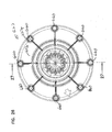
- Cartridge 605 provided with a closed end cap 627 having a plurality of projections 660 thereon.
- the projections 660 are depicted in Fig. 26 , a view of end cap 627 directed toward an outer surface 620 thereof.
- eight projections 660 radially, evenly, spaced, each generally adjacent an outer perimeter, 627p, are shown on end cap 627.
- the projections 660 can be viewed in the cross-sectional view of end cap 627, Fig. 27 .
- Each projection 660 is typically at least 10 mm long, usually at least 15 mm, and often at least 20 mm long, dimension L of Fig. 27 .
- the projections 660 provide that the cartridge 605 can be mounted in an alternate air cleaner assembly which provides a support ring engaging the projections 660, with the projections 660 extending around the support ring to provide cantilevered support. That is, the projections 660 are adapters, which allow the cartridge 605 to be installed in certain alternate air cleaners, for example with an alternate type of cantilevered support at the closed end 627 of the cartridge 605.
- FIG. 28 Attention is now directed to Fig. 28 .
- end cap 627 is depicted, toward a surface 627i, which forms an interior surface, when installed in cartridge 605, Fig. 20 .
- Hooks 670 are depicted on surface 627.
- the hooks 670 provide for mechanical interlock to a hard polyurethane potting, when end cap 627 is potted to the media 625, Fig. 20 .
- the potting is shown generally at 672, Fig. 20 .
- FIG. 21 a side elevational view of access cover 604 is shown, rotated 180° from the orientation of Fig. 20 . It is noted that projections 680 are viewable as mounts, for latches 607, but in Fig. 21 , access cover 604 is shown without latches thereon.
- FIG. 22 an end elevational view of access cover 604 is shown, the view of Fig. 22 being generally toward an exterior surface.
- an ejector port is shown at 684 .
- 650x an external view of projection 650 is shown at 650x.
- Fig. 23 is generally taken toward an interior surface of access cover 604.
- a first set of fins or ribs 685 is depicted.
- the first set of fins or ribs 685 generally comprises fins or ribs aligned radially, on an interior surface 604i of access cover 604.
- the ribs 685 then, are aligned with radii.
- the fins or ribs 685 extend along an inclined surface region of surface 604i, extending generally outwardly.
- the ribs 685 inhibit an inappropriate cartridge positioning seeking support to form an adjacent region surface 604i.
- a second set of fins or ribs 686 is provided.
- the fins or ribs 686 are generally tangential, i.e. perpendicular to radii, in the example shown there are six fins or ribs 686 generally defining an hexagonal pattern around, and spaced from, receiver 642a. These fins or ribs 686 also inhibit the use of an inappropriate surface portion within interior 604i, as a support surface for a cartridge.
- Fig. 24 is a schematic cross-sectional view generally taken along line 24-24, Fig. 22 .
- one of the fins or ribs 686 is viewable in cross-section.
- Fig. 25 is taken generally along line 25-25, Fig. 22 .
- the fins or ribs 685, 686 also provide for a stiffening of the access cover 604, in the region surrounding projection/receiver member 642.
- axial alignment ring 690 on an outer surface 627o of end cap 627.
- An opposite surface 627i, of end cap 627 is also viewable.
- ring 690 is shown in axial alignment with projection 691 on access cover 604. This region 691 of access cover 604 is also viewable in Fig. 24 .
- the alignment between projection 691 and ring 690 again helps ensure that a proper cartridge is positioned within housing 602.
- the cartridge 605 including on end cap 627, an outer, axial alignment ring 690.
- the axial alignment ring 690 is generally positioned circumscribing projection 641a, and spaced radially therefrom.
- the axial alignment ring 690 is also a region of projection axially outwardly, from adjacent potions of end cap 627.
- the axial alignment ring 690 is positioned axial aligned with, and in some instances to abut, ring 691 on cover 604. This engagement generally involves ring 690 surrounding shoulder 692, Fig. 24 , on cover 604; the shoulder 692 generally adjacent an inner portion of ring 691; the ring 691 circumscribing receiver 642a.
- an air cleaner assembly in general terms, includes an air cleaner housing defining a housing interior.
- the air cleaner housing generally comprises a housing body and an access cover.
- the housing body defines a side wall and a first end with a housing end surface and an air flow passage therethrough.
- An outlet flow tube projects both into the interior of the housing body and exterior of the housing body, the air flow passage projecting therethrough.
- the second end into the housing body, opposite the first end, is open and comprises an access end for installation and removal of the filter cartridge, during use.
- the housing generally includes an air flow inlet therein.
- the air flow inlet can be in the housing body or the access cover.
- the air flow inlet is a side inlet in the housing body. This will be typical.
- the access cover includes a member of a projection/receiver arrangement thereon.
- the access cover includes a receiver, in the form of a serpentine receiving groove on an inner surface of the cover.
- the serpentine receiving groove is defined between inner and outer serpentine side walls.
- the groove which fully extends radially around a center, comprises a plurality of alternating outwardly directed convex and inwardly directed convex (or outwardly directed concave) sections.
- the groove is configured so as not to define, within the groove, a circular path that avoids the serpentine (i.e., alternating convex outer and convex inner) sections.
- a serviceable filter cartridge is operably positioned within the housing interior.
- serviceable in this context, it is meant that the filter cartridge can be installed within the housing and then be removed from the housing, without damage to the cartridge or the housing.
- the filter cartridge comprises a media pack extending between first and second ends or end caps.
- the media pack surrounds and defines an open filter interior.
- the media pack includes filter media, and may comprise one or more of a variety of forms of media.
- a typical example comprises pleated media extending around the open interior.
- the pleated media can be provided in a cylindrical or conical form.
- the media pack can include one or both of inner and outer liners, to support the media.
- inner and outer liners can be used, including, for example, plastic liners or metal liners.
- liners when used, have open volume, for permitting air flow therethrough.
- the media When the media is pleated, it can be provided with a variety of arrangements to maintain pleat spacing including, for example, adhesive beads around the media pack, various types of corrugations in the media pack and various types of folds in the media pack.
- the first end cap of the example serviceable filter cartridge depicted has an air flow aperture therethrough.
- the example cartridge includes a seal member thereon.
- An example seal member is depicted surrounding the air flow aperture and generally positioned to surround, and seal to, an outer surface of a portion of the outlet tube on the housing, along a portion projecting into the housing interior.
- the second end cap is typically a closed end cap and includes a member of the projection/receiver arrangement thereon.
- the closed end cap includes an outer projection arrangement projecting in a direction away from the first end cap.
- the outer projection arrangement is supportably, non-rotatably, received within the receiving groove in the access cover.
- non-rotatably received within the serpentine groove it is meant that the engagement between the outer projection arrangement of the receiving groove is such that the cartridge cannot substantially rotate independently of the access cover. As a result of the engagement between the projection arrangement on the cartridge and the receiving groove, the cartridge is prevented from rotating an undesirable amount within the housing, when the access cover is in place.
- the retaining groove is a serpentine receiving groove, and the groove is a continuous groove positioned between first and second wall members.
- continuous in this context, it is meant that the groove is not interrupted by projections extending there across which would block the groove.
- the serpentine retaining groove has an innermost portion (innermost 60%) which is no greater than 14 mm wide, into which at least a portion of the projection arrangement is received. That is, the narrowest portion of the serpentine retaining groove into which at least a portion of the projection arrangement is received, is no more than 14 mm wide. Typically that portion of the retaining groove is within the range of 5 to 12 mm wide, inclusive.
- the projection arrangement extends at least 8 mm into the receiving groove, usually at least 12 mm, and often within the range of 15 to 30 mm, inclusive.
- the receiving groove is a serpentine receiving groove which comprises at least five (5) each of alternating concave and convex sections, in extension around a center.
- a serpentine receiving groove comprises a plurality of concave portions and convex portions, in extension around a center, including six (6) to ten (10) concave portions inclusive and six to ten (6-10) convex portions inclusive.
- a concave section can be viewed as an inwardly directed convex section when viewed from the interior; and, a convex section can be used as an outwardly directed concave section when viewed from the interior.
- the serpentine receiving groove comprises eight (8) convex sections (outwardly directed concave sections when viewed from the interior) and eight (8) concave sections (inwardly directed convex sections when viewed from the interior); the sections alternating with respect to one another along the extension of the serpentine retaining groove around a center.
- the serpentine receiving groove when formed from a plurality of petals having the same size and shape, can be said to have a rotational symmetry corresponding to the number of petals.
- the eight petal arrangement depicted has an eight fold symmetry around a central axis. By this it is meant that the configuration can be rotated 1/8 of a turn and still align with itself, 2/8 of a turn, etc.
- a similar symmetry is provided in the typical projection arrangement, depicted.
- the access cover is provided with an outer, for example circular, side wall.
- the circular side wall can, in some instances, surround portions of the cartridge, in the assembled housing.
- the air filter cartridge is positioned in a housing with no portion of the access cover surrounding the air filter cartridge other than the outer (circular) side wall. That is, there is no internal shield or flange, or cartridge support arrangement, or air flow directing arrangement, which surrounds the cartridge at the closed end and which is inwardly spaced from the outer wall of the access cover.
- the access cover includes an inner surface with a projection region.
- the projection region includes the receiving groove therein, and comprises an inner wall and an outer wall each of which is serpentine.
- a fin arrangement is shown extending radially outwardly from the projection region.
- Each of the fins projects generally toward the first end of the housing, from the access cover.
- the fins provide strength and rigidity to the portion of the access cover in which they are positioned.
- the fins can be used to inhibit cartridge support by the access cover in a manner that does not involve the receiving groove.
- the fins are configured to inhibit support of the cartridge by projection into the cartridge, the fins are sometimes referred to herein as an "anti-cantilevered support" arrangement.
- the access cover includes a second fin arrangement thereon, this fin arrangement comprising a plurality of tangentially oriented fins or ribs defining a straight-sided pattern around a projection region (including a recess) on the inner surface of the access cover.
- this fin arrangement comprises six fins or ribs defining a generally hexagonal pattern. These fins or ribs provide stiffening in the access cover, as well as inhibit an inappropriate cartridge from obtaining support by the access cover 604.
- the projection arrangement on the filter cartridge generally includes at least one radially outwardly convex portion.
- the convex portion is typically positioned on a curve that does not correspond to a circle centered around a center point of the second end cap.
- the projection arrangement on the serviceable filter cartridge includes at least one radially inwardly convex portion (i.e., at least one radially outwardly concave portion.)
- the projection arrangement on the serviceable filter cartridge includes a plurality of radially outwardly convex portions and a plurality of radially inwardly convex portions sometimes referenced as outward concave portions.
- these portions form a continuous, serpentine, wall.
- the particular example of a continuous serpentine wall depicted in the drawings, is a closed, continuous, solid wall, i.e., it has no apertures therethrough and is not hollow.
- the projection arrangement of the serviceable filter cartridge projects away from an immediately adjacent region of the second end cap a distance of at least 10 mm, usually at least 15 mm and often within the range of 20 to 40 mm, inclusive.
- the projection arrangement of the serviceable filter cartridge projects axially outwardly beyond an end of the media pack a distance of at least 10 mm, usually at least 15 mm and often within the range of 20 to 80 mm. That is, in a typical arrangement, the projection arrangement is not part of a deep, inner, well, in the second end cap, which projects into the cartridge.
- filter cartridge includes an axial alignment ring on an outer surface of the closed end cap, surrounding and spaced from a projection on the closed end cap.
- the axial alignment ring is positioned to align, and in some instances abut, an alignment ring positioned on an inner surface of the access cover, surrounding and spaced from the receiver arrangement on the access cover.
- An inner shoulder of the ring in the access cover can be surrounded by the axial alignment ring on the filter cartridge, when installed.
- an air filter cartridge arrangement is provided.
- the air filter cartridge is useable as a serviceable filter cartridge, in a air cleaner assembly.
- An example of an air filter cartridge (and the corresponding air cleaner assembly) is described and depicted.
- the air filter cartridge includes a media pack surrounding an open interior having first and second opposite ends.
- the media pack includes filter media.
- the media can be a variety of types of media, but will typically be pleated media.
- the media pack can also include one or both of an inner and outer media support liner. Typically plastic and/or metal liners would be used.
- the media pack can be configured in a cylindrical shape or a conical shape.
- the cartridge includes a first end cap positioned on the first end of the media pack.
- the first end cap has a central air flow aperture therethrough.
- a seal is provided on the closed end cap.
- an inwardly directed radial seal is provided on the first end cap surrounding the air flow aperture.
- This radial seal can comprise an integral molded portion of the end cap, although alternatives are possible.
- the first end cap will typically be molded-in-place, for example from polyurethane foam.
- a second end cap is positioned on the second end of the media pack, opposite the first end cap.
- the second end cap is typically a closed end cap.
- the second end cap includes a projection arrangement thereon projecting away from the first end cap.
- the projection arrangement is non-circular and includes at least one arcuate section; the at least one arcuate section having or defining an arc curve which is not co-extensive with a circle surrounding a center point of the end cap.
- the at least one arcuate section can comprise a portion of a projection arrangement including a plurality of outwardly projecting convex sections, and inwardly directed convex sections, for example alternating in a serpentine arrangement.
- the serpentine arrangement can comprise a single, continuous, wall around a center of the end cap.
- the second end cap of the cartridge can further include an axial alignment ring on an outer surface thereof.
- the axial alignment ring is generally positioned surrounding, and radially spaced from, the projection on the second end cap. This ring is positioned to align with the axial alignment ring on the access cover, when the cartridge is properly installed.
- an air filter cartridge comprising:
- the invention provides an air filter arrangement according to any one of the above embodiments wherein:
- the invention provides an air filter arrangement according to any one of the above embodiments wherein:
- the invention provides an air filter arrangement according to any one of the above embodiments wherein:
- the invention provides an air filter arrangement according to any one of the above embodiments wherein:
- an air cleaner assembly comprising:
- an air cleaner assembly comprising:
- the invention provides an air cleaner assembly according to any one of the above embodiments wherein:
- the invention provides an air cleaner assembly according to any one of the above embodiments wherein:
- the invention provides an air cleaner assembly according to any one of the above embodiments wherein:
- the invention provides an air cleaner assembly according to any one of the above embodiments wherein:
- the invention provides an air cleaner assembly according to the above embodiment wherein:
- the invention provides an air cleaner assembly according to any one of the above embodiments wherein:
- the invention provides an air cleaner assembly according to any one of the above embodiments wherein:
- the invention provides an air cleaner assembly according to any one of the above embodiments wherein:
- the invention provides an air cleaner assembly according to any one of the above embodiments wherein:
- an air cleaner assembly comprising:
- the invention provides an air cleaner assembly according to any one of the above embodiments wherein:
- the invention provides an air cleaner assembly according to any one of the above embodiments wherein:
- an air filter cartridge comprising:
- an air filter cleaner assembly comprising:
Priority Applications (1)
| Application Number | Priority Date | Filing Date | Title |
|---|---|---|---|
| PL12178152T PL2570170T3 (pl) | 2007-07-20 | 2008-07-17 | Układy filtra powietrza i wkłady |
Applications Claiming Priority (5)
| Application Number | Priority Date | Filing Date | Title |
|---|---|---|---|
| US96152207P | 2007-07-20 | 2007-07-20 | |
| US96152107P | 2007-07-20 | 2007-07-20 | |
| US7216208P | 2008-03-27 | 2008-03-27 | |
| US12622208P | 2008-04-30 | 2008-04-30 | |
| EP20080781967 EP2175960B1 (de) | 2007-07-20 | 2008-07-17 | Luftreinigeranordnung mit endstütze für eine patrone |
Related Parent Applications (2)
| Application Number | Title | Priority Date | Filing Date |
|---|---|---|---|
| EP20080781967 Division EP2175960B1 (de) | 2007-07-20 | 2008-07-17 | Luftreinigeranordnung mit endstütze für eine patrone |
| EP08781967.8 Division | 2008-07-17 |
Publications (2)
| Publication Number | Publication Date |
|---|---|
| EP2570170A1 true EP2570170A1 (de) | 2013-03-20 |
| EP2570170B1 EP2570170B1 (de) | 2018-01-31 |
Family
ID=39855075
Family Applications (4)
| Application Number | Title | Priority Date | Filing Date |
|---|---|---|---|
| EP17206196.2A Active EP3384972B1 (de) | 2007-07-20 | 2008-07-17 | Luftreinigeranordnung |
| EP20080781967 Active EP2175960B1 (de) | 2007-07-20 | 2008-07-17 | Luftreinigeranordnung mit endstütze für eine patrone |
| EP12178162.9A Active EP2570171B1 (de) | 2007-07-20 | 2008-07-17 | Luftreinigeranordnung |
| EP12178152.0A Active EP2570170B1 (de) | 2007-07-20 | 2008-07-17 | Luftreinigeranordnung und patronen |
Family Applications Before (3)
| Application Number | Title | Priority Date | Filing Date |
|---|---|---|---|
| EP17206196.2A Active EP3384972B1 (de) | 2007-07-20 | 2008-07-17 | Luftreinigeranordnung |
| EP20080781967 Active EP2175960B1 (de) | 2007-07-20 | 2008-07-17 | Luftreinigeranordnung mit endstütze für eine patrone |
| EP12178162.9A Active EP2570171B1 (de) | 2007-07-20 | 2008-07-17 | Luftreinigeranordnung |
Country Status (11)
| Country | Link |
|---|---|
| US (6) | US8292984B2 (de) |
| EP (4) | EP3384972B1 (de) |
| AR (1) | AR067596A1 (de) |
| CL (1) | CL2008002123A1 (de) |
| DE (3) | DE202008018224U1 (de) |
| ES (2) | ES2665993T3 (de) |
| LT (2) | LT2570171T (de) |
| PE (1) | PE20090545A1 (de) |
| PL (3) | PL2570170T3 (de) |
| RU (2) | RU2666421C2 (de) |
| WO (1) | WO2009014982A1 (de) |
Families Citing this family (83)
| Publication number | Priority date | Publication date | Assignee | Title |
|---|---|---|---|---|
| CN100406102C (zh) | 2002-10-28 | 2008-07-30 | 唐纳森公司 | 空气清洁器、可更换的过滤器筒及其制造方法 |
| US8529324B2 (en) * | 2003-04-17 | 2013-09-10 | The Sy-Klone Company | Powered air cleaning system and method of making same |
| WO2007056589A2 (en) | 2005-11-09 | 2007-05-18 | Donaldson Company, Inc. | Seal arrangement for filter element; filter element assembly: and, methods |
| US7520913B2 (en) | 2005-02-04 | 2009-04-21 | Donaldson Company, Inc. | Non-cylindrical filter elements, and methods |
| EP2664372A1 (de) | 2006-10-06 | 2013-11-20 | Donaldson Company, Inc. | Luftreiniger, auswechselbare Filterpatronen und Verfahren |
| US8414675B2 (en) * | 2007-04-03 | 2013-04-09 | Donaldson Company, Inc. | Air cleaner; air filter cartridge and method of manufacturing |
| US8404029B2 (en) | 2007-06-14 | 2013-03-26 | Donaldson Company, Inc. | Crankcase ventilation filter arrangments; components; and, methods |
| US8292984B2 (en) | 2007-07-20 | 2012-10-23 | Donaldson Company, Inc. | Air cleaner arrangments with end support for cartridge; components; and, methods |
| US8066791B2 (en) | 2007-07-20 | 2011-11-29 | Donaldson Company, Inc. | Air cleaner arrangements with internal and external support for cartridge; components; and, methods |
| AU2008320948B2 (en) | 2007-11-15 | 2013-08-15 | Donaldson Company, Inc. | Air filter arrangements; assemblies; and, methods |
| CN102159297B (zh) | 2008-07-22 | 2014-12-17 | 唐纳森公司 | 空气滤清器组件及其部件 |
| EP3085427B1 (de) | 2009-03-31 | 2020-12-02 | Donaldson Company, Inc. | Flüssigkeitsfilteranordnung und flüssigkeitsfilterpatrone |
| DE202009016500U1 (de) | 2009-12-07 | 2010-02-25 | Mahle International Gmbh | Filterelement und Luftfilter |
| WO2011088374A2 (en) * | 2010-01-15 | 2011-07-21 | Perry Equipment Corporation | Natural gas production filtration vessel and assembly |
| CN102741537B (zh) | 2010-01-29 | 2016-01-06 | 唐纳森公司 | 用于空气滤清器的水分离器组件及发动机空气流入口结构 |
| CN102933278A (zh) | 2010-05-18 | 2013-02-13 | 唐纳森公司 | 具有过滤元件的空气滤清器组件和用于安装过滤元件的方法 |
| CN102958581B (zh) * | 2010-09-16 | 2016-02-10 | 康明斯过滤Ip公司 | 具有对预先清理性能、密封及结构支承进行改进的特征的过滤单元 |
| EP2654921B1 (de) | 2010-12-22 | 2021-07-07 | Donaldson Company, Inc. | Filter für eine kurbelgehäuseentlüftung |
| DE102011008325B4 (de) | 2011-01-11 | 2016-12-15 | Carl Freudenberg Kg | Keilförmiges Filterelement mit zwei Plattenfiltern und dessen Verwendung |
| DE102011011595A1 (de) | 2011-02-17 | 2012-08-23 | Mann + Hummel Gmbh | Filterelement |
| JP2014507277A (ja) | 2011-02-25 | 2014-03-27 | ドナルドソン カンパニー,インコーポレイティド | エアフィルタカートリッジ、その構成要素及びエアクリーナアセンブリ |
| US11235274B2 (en) | 2011-06-30 | 2022-02-01 | Donaldson Company, Inc. | Filter systems; components; features; and, methods of assembly and use |
| US8657928B2 (en) | 2011-07-29 | 2014-02-25 | The Sy-Klone Company | Versatile compact air precleaner, air cleaning method and disposable air filter cartridge for air precleaner |
| US8475556B2 (en) * | 2011-10-05 | 2013-07-02 | Mann + Hummel Gmbh | Filter cartridge system |
| KR102031390B1 (ko) | 2011-10-26 | 2019-11-08 | 도날드슨 컴파니, 인코포레이티드 | 필터 조립체, 그 부품 및 특징부, 및 사용 및 조립 방법 |
| US9387425B2 (en) | 2011-10-26 | 2016-07-12 | Donaldson Company, Inc. | Filter assemblies; components and features thereof; and, methods of use and assembly |
| WO2014029811A1 (de) * | 2012-08-22 | 2014-02-27 | Mann+Hummel Gmbh | Filtereinrichtung, insbesondere zur gasfiltration |
| US9089804B2 (en) | 2012-11-19 | 2015-07-28 | Donaldson Company, Inc. | Filter arrangements; components; assemblies; and, methods |
| US9914084B2 (en) | 2012-11-19 | 2018-03-13 | Donaldson Company, Inc. | Filter arrangements; components; assemblies; and methods |
| US20140144111A1 (en) | 2012-11-29 | 2014-05-29 | Donaldson Company Inc. | Filter cartridges; features and methods of assemlby; air cleaner assemblies; and, filter cartridge combinations |
| US9086007B2 (en) * | 2012-12-21 | 2015-07-21 | Caterpillar Inc. | System and method for accommodating aftertreatment bricks |
| DE102014000927A1 (de) | 2013-02-12 | 2014-08-14 | Mann + Hummel Gmbh | Filterelement |
| DE102014001608A1 (de) | 2013-02-12 | 2014-08-28 | Mann+Hummel Gmbh | Luftfilterelement |
| CN108412645B (zh) * | 2013-05-22 | 2020-10-16 | 唐纳森公司 | 空气滤清器和过滤元件 |
| US10118120B2 (en) | 2013-05-31 | 2018-11-06 | Donaldson Company, Inc. | Filter cartridge arrangements and assemblies; preferred features; methods of assembly and use |
| US9726123B2 (en) * | 2013-06-20 | 2017-08-08 | Mann+Hummel Gmbh | Air filter, filter element and filter housing of an air filter |
| US10436155B2 (en) | 2013-06-20 | 2019-10-08 | Mann+Hummel Gmbh | Air filter, filter element and filter housing of an air filter |
| DE102014006853B4 (de) * | 2013-06-20 | 2022-10-27 | Mann+Hummel Gmbh | Hohlfilterelement, Filtergehäuse und Filter |
| US10239005B2 (en) * | 2013-06-20 | 2019-03-26 | Mann+Hummel Gmbh | Filter housing, hollow filter element and filter |
| US9815012B2 (en) * | 2013-06-24 | 2017-11-14 | Pecofacet (Us), Inc. | Filter elements, coalescing baffles, filtration vessel and methods |
| US11071934B2 (en) | 2013-06-24 | 2021-07-27 | Parker-Hannifin Corporation | Filter elements, coalescing baffles, filtration vessel and methods |
| US9933116B2 (en) | 2013-08-02 | 2018-04-03 | Alternative Fuel Containers, Llc | Vehicle fuel gas pre-filter unit |
| US9457308B2 (en) * | 2013-09-02 | 2016-10-04 | Mann+Hummel Gmbh | Filter element and filter system with a filter element |
| DE102014014748A1 (de) | 2013-10-30 | 2015-04-30 | Mann + Hummel Gmbh | Filterelement und Filteranordnung |
| DE202014100770U1 (de) | 2014-02-21 | 2014-03-06 | Diesel Technic Ag | Luftfilterpatrone |
| JP2016011023A (ja) * | 2014-06-27 | 2016-01-21 | ヤマハ発動機株式会社 | 車両 |
| DE102014012578B4 (de) | 2014-08-29 | 2023-06-07 | Mann+Hummel Gmbh | Filtersystem und dessen Verwendung |
| DE102014012579B4 (de) | 2014-08-29 | 2023-06-15 | Mann+Hummel Gmbh | Filterelement, dessen Verwendung und Filtersystem |
| US9517428B2 (en) | 2014-09-12 | 2016-12-13 | Illinois Tool Works Inc. | Filter for a portable industrial air filtration device |
| WO2016082854A1 (en) * | 2014-11-24 | 2016-06-02 | Mann+Hummel Gmbh | Filtering device, filtering element and maintenance process of a filtering device |
| BR122022010023B1 (pt) | 2015-03-02 | 2023-03-07 | Donaldson Company, Inc | Cartucho de filtro de ar |
| JP6519862B2 (ja) * | 2015-05-11 | 2019-05-29 | Smc株式会社 | 空気圧フィルタ及びフィルタエレメント |
| US10035086B2 (en) * | 2015-05-11 | 2018-07-31 | Cummins Filtration Ip, Inc. | Filter cartridge for clean servicing |
| US10029198B2 (en) | 2015-06-25 | 2018-07-24 | Donaldson Company, Inc. | Assemblies; components and filter features thereof; and, methods of use and assembly |
| USD767746S1 (en) | 2015-07-14 | 2016-09-27 | The Sy-Klone Company | Filter cartridge for air cleaner |
| USD768277S1 (en) | 2015-07-14 | 2016-10-04 | The Sy-Klone Company | Filter cartridge for air cleaner |
| USD768833S1 (en) | 2015-07-14 | 2016-10-11 | The Sy-Klone Company | Filter cartridge for air cleaner |
| AU2017217863B2 (en) | 2016-02-12 | 2022-09-29 | Donaldson Company, Inc. | Filter elements, air cleaner assemblies, and methods of use and assembly |
| USD800883S1 (en) * | 2016-04-23 | 2017-10-24 | Nick Trask | Air cleaner |
| USD800609S1 (en) * | 2016-04-23 | 2017-10-24 | Nick Trask | Motorcycle with air cleaner |
| KR101776494B1 (ko) | 2016-04-28 | 2017-09-07 | 현대자동차주식회사 | 라운드형 차량용 에어필터와 이를 포함하는 차량용 에어클리너 어셈블리 |
| DE102016005356A1 (de) * | 2016-05-03 | 2017-11-09 | Mann+Hummel Gmbh | Filterelement, insbesondere zur Gasfiltration, und Filtereinrichtung |
| CN109689180B (zh) | 2016-06-17 | 2022-12-02 | 唐纳森公司 | 空气滤清器组件和滤芯 |
| US10617985B2 (en) * | 2016-09-29 | 2020-04-14 | Rosemount Inc. | Gas sensor module with field replaceable, ingress protected, sensor filter |
| US9861922B1 (en) * | 2016-10-14 | 2018-01-09 | Holley Performance Products, Inc. | Mating interface between air intake housing and air filter |
| EP3311902B1 (de) * | 2016-10-24 | 2020-06-24 | Donaldson Company, Inc. | Luftfilterelement und verfahren zur herstellung davon |
| CN110248716B (zh) | 2016-12-01 | 2021-09-28 | 唐纳森公司 | 滤芯、空气滤清器组件、以及使用和组装方法 |
| US10508624B2 (en) * | 2017-02-27 | 2019-12-17 | Baldwin Filters, Inc. | Air filter with cantilever tab and engine air filter assembly incorporating same |
| EP3401000A1 (de) | 2017-05-09 | 2018-11-14 | Donaldson Company, Inc. | Adapter und luftfilterpatrone zur verwendung mit solch einem adapter |
| US10864469B2 (en) | 2017-06-05 | 2020-12-15 | Donaldson Company, Inc. | Air cleaner assemblies and methods of use |
| US11136947B2 (en) * | 2017-06-27 | 2021-10-05 | Parker-Hannifin Corporation | Air cleaner with high performance seal and media |
| WO2019032707A1 (en) | 2017-08-09 | 2019-02-14 | Donaldson Company, Inc. | FILTER CARTRIDGES, AIR PURIFYING ASSEMBLIES, HOUSINGS, CHARACTERISTICS, CONSTITUENT ELEMENTS AND METHODS |
| EP3675983B1 (de) | 2017-08-31 | 2023-04-26 | Donaldson Company, Inc. | Filterpatronen, luftreinigeranordnungen |
| EP3720585A4 (de) | 2017-12-04 | 2021-08-04 | Parker-Hannifin Corporation | Drallfreier einpressfilter-spud |
| CN114425195B (zh) | 2018-01-12 | 2023-08-04 | 康明斯滤清系统知识产权公司 | 易于维修的空气过滤器 |
| CN115671902A (zh) * | 2018-01-24 | 2023-02-03 | 唐纳森公司 | 过滤器元件、系统和方法 |
| USD1002792S1 (en) | 2019-02-05 | 2023-10-24 | Donaldson Company, Inc. | Filter cartridge |
| USD913860S1 (en) * | 2019-06-25 | 2021-03-23 | Arlen Ness Enterprises, Inc. | Motorcycle air cleaner |
| US11565208B2 (en) | 2021-06-22 | 2023-01-31 | Caterpillar Inc. | Air filter element with pre-cleaning tubes |
| DE102022108749A1 (de) | 2022-04-11 | 2023-10-12 | Mann+Hummel Gmbh | Luftfilter mit einer Führungseinrichtung zur Abstützung eines Filterelements in einem Gehäusetopf und Filtergehäuse |
| EP4279164A1 (de) | 2022-05-18 | 2023-11-22 | MANN+HUMMEL GmbH | Filtersystem und filterelement |
| EP4344763A1 (de) | 2022-09-29 | 2024-04-03 | MANN+HUMMEL GmbH | Filterelement und filtersystem |
| CN115822827B (zh) * | 2023-02-13 | 2023-05-02 | 杭州土星动力科技有限公司 | 发动机进气装置 |
Citations (9)
| Publication number | Priority date | Publication date | Assignee | Title |
|---|---|---|---|---|
| US5547480A (en) | 1994-01-21 | 1996-08-20 | Donaldson Company, Inc. | Cylindrical air filter with radially directed seal |
| US6039778A (en) | 1997-09-12 | 2000-03-21 | Donaldson Company, Inc. | Air cleaner assembly |
| US6652614B2 (en) | 2000-12-04 | 2003-11-25 | Donaldson Company, Inc. | Filter system; element configuration; and methods |
| US6955701B2 (en) | 2002-03-28 | 2005-10-18 | Donaldson Company, Inc. | Filter element and use thereof; methods of manufacture |
| US20060086075A1 (en) * | 2002-10-28 | 2006-04-27 | Scott James R | Filter cartridges; air cleaners; and methods |
| WO2006119414A1 (en) * | 2005-05-03 | 2006-11-09 | Donaldson Company, Inc. | Air cleaner; air filter cartridge and method of manufacturing |
| US20060254229A1 (en) | 2005-05-03 | 2006-11-16 | Kevin Schrage | Air cleaner; air filter cartridge and method of manufacturing |
| WO2007009040A1 (en) | 2005-07-13 | 2007-01-18 | Donaldson Company, Inc. | Air filter cartridge and air cleaner |
| EP1754525A1 (de) * | 2005-08-16 | 2007-02-21 | Donaldson Company, Inc. | Luftreiniger mit verdrehsicherer Anordnung und zugehörige Verfahren |
Family Cites Families (177)
| Publication number | Priority date | Publication date | Assignee | Title |
|---|---|---|---|---|
| US2771156A (en) | 1953-10-22 | 1956-11-20 | Bendix Aviat Corp | Filter |
| US3048959A (en) * | 1959-10-27 | 1962-08-14 | Novo Ind Corp | Air cleaning device and method |
| FR1216783A (fr) | 1960-09-27 | 1960-04-27 | Fram Corp | Filtre à liquides |
| US3169844A (en) * | 1961-01-24 | 1965-02-16 | Wix Corp | Air filter |
| US3078650A (en) * | 1961-03-20 | 1963-02-26 | Donaldson Co Inc | Air cleaner |
| US3160488A (en) | 1962-01-26 | 1964-12-08 | Dollinger Corp | Filter |
| US3290870A (en) | 1963-11-21 | 1966-12-13 | Walker Mfg Co | Disposable air filter for internal combustion engines |
| US3354012A (en) | 1964-01-14 | 1967-11-21 | Pall Corp | Process and apparatus for capping filter elements |
| US3342021A (en) | 1964-11-19 | 1967-09-19 | Walker Mfg Co | Filter |
| GB1050559A (de) | 1964-12-08 | |||
| US3357163A (en) | 1965-06-14 | 1967-12-12 | Ford Motor Co | Air cleaner assembly for tractors |
| GB1125335A (en) | 1966-03-22 | 1968-08-28 | Westinghouse Brake & Signal | Improvements relating to water activated primary cells |
| GB1124735A (en) | 1966-07-23 | 1968-08-21 | Stone Filter Company Inc | Improvements relating to filters |
| US3452519A (en) * | 1967-02-06 | 1969-07-01 | Caterpillar Tractor Co | Pressure stabilizing vent system for hydraulic circuit fluid reservoirs |
| US3413780A (en) | 1967-05-10 | 1968-12-03 | Gen Motors Corp | Air cleaner and silencer assembly |
| US3488928A (en) * | 1967-05-19 | 1970-01-13 | Dollinger Corp | Dual filter |
| US3423909A (en) * | 1967-09-28 | 1969-01-28 | Novo Ind Corp | Air cleaner with improved filter element assembly |
| US3584439A (en) * | 1968-06-20 | 1971-06-15 | Donaldson Co Inc | Fluid cleaner |
| US3616618A (en) | 1969-08-13 | 1971-11-02 | Donaldson Co Inc | Air filter gasket element |
| US3716436A (en) * | 1970-03-16 | 1973-02-13 | Pall Corp | Process for making a back pressure resistant filter element |
| US3672130A (en) * | 1970-04-02 | 1972-06-27 | Donaldson Co Inc | Retention means for air cleaner element |
| US3710560A (en) * | 1970-09-25 | 1973-01-16 | Fram Corp | Air cleaner |
| FR2261041B1 (de) | 1974-02-18 | 1978-03-31 | Cfea | |
| US4498915A (en) * | 1974-03-29 | 1985-02-12 | Witchell Stanley P | Air filters |
| FR2268551B1 (de) | 1974-04-24 | 1980-12-05 | Cfea | |
| US4036616A (en) * | 1974-05-01 | 1977-07-19 | Robert A. Baker | Bacteria filter and method of assembling same |
| US4006000A (en) * | 1974-06-06 | 1977-02-01 | United Filtration Corporation | All dry air cleaner |
| US4062781A (en) | 1976-06-04 | 1977-12-13 | Whatman Reeve Angel Limited | Disposable filter with interchangeable end elements |
| US4135899A (en) * | 1977-05-25 | 1979-01-23 | Donaldson Company, Inc. | Safety filter for air cleaner |
| US4128251A (en) | 1977-09-21 | 1978-12-05 | Champion Laboratories, Inc. | Sealing gasket for air filter |
| US4159197A (en) * | 1977-10-05 | 1979-06-26 | Donaldson Company, Inc. | Suspension gasket seal and system for baghouse filter units |
| JPS6045306B2 (ja) | 1978-01-31 | 1985-10-08 | ヤマハ発動機株式会社 | エアクリ−ナ |
| US4211543A (en) * | 1978-04-24 | 1980-07-08 | Donaldson Company, Inc. | Air cleaner with replaceable filter element |
| US4222755A (en) | 1978-11-17 | 1980-09-16 | Grotto Lavon P | Air filter arrangement to permit cleaning without removing element |
| US4235611A (en) | 1979-04-23 | 1980-11-25 | Fram Corporation | Air filter |
| US4238540A (en) | 1979-05-29 | 1980-12-09 | Celanese Corporation | Fiber reinforced composite shaft with metallic connector sleeves mounted by connector ring interlock |
| JPS5936685Y2 (ja) * | 1979-05-30 | 1984-10-09 | 株式会社デンソー | エアクリ−ナ |
| US4279275A (en) | 1979-08-06 | 1981-07-21 | Ford Aerospace & Communications Corporation | Mechanical joinder of composite shaft to metallic end members |
| SU868082A1 (ru) | 1979-12-03 | 1981-09-30 | Предприятие П/Я В-8735 | Воздухоочиститель |
| US4303426A (en) | 1980-03-14 | 1981-12-01 | Robert Battis | Automobile air filter having replaceable and readily disposable filter element |
| US4349363A (en) | 1980-10-27 | 1982-09-14 | Incom International Inc. | Filter element ledge gasket |
| US4350509A (en) | 1981-07-24 | 1982-09-21 | Donaldson Company, Inc. | Disposable air cleaner |
| DE3140128C2 (de) | 1981-10-09 | 1984-05-30 | Filterwerk Mann & Hummel Gmbh, 7140 Ludwigsburg | Ansaugluftfilter für Brennkraftmaschinen, Kompressoren und sonstige luftansaugende Maschinen |
| US4402830A (en) | 1982-01-13 | 1983-09-06 | Pall Corporation | Corrugated filter element with external spiral tape support |
| GB2119674B (en) | 1982-05-05 | 1985-10-30 | Marshall D A G | Air filter element |
| US4491460A (en) * | 1983-01-31 | 1985-01-01 | Donaldson Company, Inc. | Air cleaner and deflecting intake tube |
| US4488889A (en) | 1983-03-07 | 1984-12-18 | Mccarroll Glenn G | Air cleaner tank |
| FR2546767B1 (fr) * | 1983-06-02 | 1985-08-23 | Peugeot Aciers Et Outillage | Filtre perfectionne, notamment filtre a air pour moteur a combustion interne |
| US4609465A (en) | 1984-05-21 | 1986-09-02 | Pall Corporation | Filter cartridge with a connector seal |
| GB2163368B (en) | 1984-08-20 | 1988-05-05 | Marshall D A G | Filter element |
| US4801383A (en) * | 1984-11-19 | 1989-01-31 | Memtec North America Corp. | Selective twist filtration roving |
| JPS6219217A (ja) * | 1985-07-17 | 1987-01-28 | Nippon Shiyuumatsuhaa Kk | 濾過装置における濾過エレメント |
| DE3603043A1 (de) | 1986-01-31 | 1987-08-06 | Knorr Bremse Ag | Trocknungspatrone fuer lufttrocknungsanlagen, insbesondere fuer druckluftbremsanlagen von fahrzeugen |
| US5045192A (en) | 1986-06-03 | 1991-09-03 | Facet Enterprises, Inc. | Filter assembly with lockable lug means |
| US4720292B1 (en) * | 1986-07-14 | 1991-09-10 | Cylindrical air filter with lightweight housing and radially directed seal | |
| US4764191A (en) * | 1987-10-05 | 1988-08-16 | Aldo Morelli | Air filter |
| US4818261A (en) * | 1987-10-15 | 1989-04-04 | Beckon Weir E | Reversed pulse cleaning filter |
| US4838901A (en) * | 1988-05-17 | 1989-06-13 | Life Systems, Inc. | Lightweight filter |
| US5290445A (en) * | 1988-05-27 | 1994-03-01 | Pall Corporation | Filtering apparatus |
| US4950317A (en) * | 1989-01-09 | 1990-08-21 | Donaldson Company, Inc. | Air filter assembly and method of putting filter element in same |
| SE8902441L (sv) * | 1989-07-05 | 1991-01-06 | Volvo Ab | Filteranordning, i synnerhet insugningsfilter foer foerbraenningsmotorer |
| SE500902C2 (sv) | 1989-07-05 | 1994-09-26 | Volvo Ab | Filteranordning, i synnerhet insugningsfilter för förbränningsmotorer |
| SE8902440L (sv) | 1989-07-05 | 1991-01-06 | Volvo Ab | Filteranordning, isynnerhet insugningsluftfilter foer foerbraenningsmotorer |
| DE3934433A1 (de) | 1989-10-14 | 1991-04-25 | Mann & Hummel Filter | Luftfilter mit radial abdichtendem filtereinsatz |
| US5118417A (en) * | 1990-01-25 | 1992-06-02 | Deibel Richard J | High-strength disposable tube filter |
| US5116499A (en) * | 1990-02-25 | 1992-05-26 | Deibel Richard J | High-strength spin-on tube filter |
| US5064458A (en) | 1990-03-07 | 1991-11-12 | Allied-Signal Inc. | Heavy duty air filter with multipurpose end seal |
| FR2665217A1 (fr) | 1990-07-30 | 1992-01-31 | Sacatec | Entonnoir a cartouche filtrante echangeable destine a etre monte sur les pots d'echappement de gaz des vehicules automobiles. |
| US5211846A (en) * | 1990-07-30 | 1993-05-18 | Pleatco Electronic & Filter Corp. | Replacement filter cartridge assembly |
| DE9011419U1 (de) * | 1990-08-06 | 1990-10-11 | Filterwerk Mann & Hummel Gmbh, 7140 Ludwigsburg, De | |
| DE4024898A1 (de) | 1990-08-06 | 1992-02-13 | Mann & Hummel Filter | Ansaugluftfilter fuer die verbrennungskraftmaschine eines fahrzeugs |
| US5082476A (en) * | 1990-10-19 | 1992-01-21 | Donaldson Company, Inc. | Filtration arrangement and method |
| DE4034216C1 (de) * | 1990-10-27 | 1992-06-17 | Filterwerk Mann & Hummel Gmbh, 7140 Ludwigsburg, De | |
| US5112417A (en) * | 1991-05-20 | 1992-05-12 | United States Of America | Method of controlling the increase in potlife of propellants during processing |
| DE4203864C2 (de) * | 1992-02-11 | 1993-12-02 | Deere & Co | Positioniereinrichtung für Luftfilter |
| US5250179A (en) | 1992-03-27 | 1993-10-05 | Porous Media Corporation | Compactable filter and compactable filter mounting means |
| DE9204169U1 (de) | 1992-03-27 | 1992-06-11 | Rapp, Peter, 7114 Pfedelbach, De | |
| DE4241586C1 (de) * | 1992-12-10 | 1994-01-27 | Mann & Hummel Filter | Luftfilter |
| US5476585A (en) * | 1993-02-24 | 1995-12-19 | Pall Corporation | Removably mounted hollow filter element and core |
| US5921982A (en) * | 1993-07-30 | 1999-07-13 | Lesh; Michael D. | Systems and methods for ablating body tissue |
| US5431168A (en) * | 1993-08-23 | 1995-07-11 | Cordis-Webster, Inc. | Steerable open-lumen catheter |
| US5487767A (en) | 1993-09-30 | 1996-01-30 | Dana Corporation | Radially sealed air filters |
| DE4428139C2 (de) * | 1993-10-27 | 1996-10-02 | Mann & Hummel Filter | Filtereinrichtung |
| US5484466A (en) * | 1994-02-14 | 1996-01-16 | Baldwin Filters, Inc. | Air filter element with radial seal sealing gasket |
| US5632791A (en) * | 1994-12-06 | 1997-05-27 | Bha Group, Inc. | Unitary filter cartridge |
| US5442721A (en) * | 1994-08-08 | 1995-08-15 | The United States Of America As Represented By The Secretary Of The Navy | Fiber-optic rotary joint with bundle collimator assemblies |
| JP3468436B2 (ja) * | 1994-09-22 | 2003-11-17 | 豊田紡織株式会社 | 樹脂製エアクリーナ |
| US5556440A (en) * | 1994-10-20 | 1996-09-17 | Fleetguard, Inc. | Pressure-actuated radial air filter seal |
| FR2726483B1 (fr) * | 1994-11-09 | 1997-01-24 | Siebec Sa | Cartouche filtrante a couronne mobile de maintien |
| US5613992A (en) * | 1994-11-23 | 1997-03-25 | Donaldson Company, Inc. | Reverse flow air filter arrangement and method |
| US5938804A (en) | 1994-11-23 | 1999-08-17 | Donaldson Company, Inc. | Reverse flow air filter arrangement and method |
| DE4441608C2 (de) * | 1994-11-23 | 1997-07-17 | Mann & Hummel Filter | Filteranordnung |
| US6004366A (en) * | 1994-11-23 | 1999-12-21 | Donaldson Company, Inc. | Reverse flow air filter arrangement and method |
| US5545241B1 (en) | 1995-01-17 | 1999-09-28 | Donaldson Co Inc | Air cleaner |
| DE29501276U1 (de) | 1995-01-27 | 1995-04-13 | Lin Tsun Huo | Hinterradnabenübertragungsmechanismus |
| US5669949A (en) | 1995-04-21 | 1997-09-23 | Donaldson Company, Inc. | Air filtration arrangement |
| DE19519438A1 (de) * | 1995-05-26 | 1996-11-28 | Mann & Hummel Filter | Luftfilter, insbesondere für die Reinigung von Verbrennungsluft für Brennkraftmaschinen |
| US5605555A (en) * | 1995-05-30 | 1997-02-25 | Air-Maze Corporation | Air/oil separator with interlocked flange |
| DE19520156A1 (de) | 1995-06-01 | 1996-12-05 | Mann & Hummel Filter | Filter, insbesondere Luftfilter für die Ansaugluft einer Brennkraftmaschine |
| US5720788A (en) * | 1995-06-30 | 1998-02-24 | Dana Corporation | Air filter element and air filter assembly employing the filter element |
| CA2197794A1 (en) * | 1995-07-05 | 1997-01-23 | Jhina U. Patel | Air cleaner having removable end cap |
| US5984109A (en) | 1995-07-10 | 1999-11-16 | Western Filter Corporation | Filter assembly including a disposable coreless filter element |
| DE19547575A1 (de) * | 1995-12-20 | 1997-06-26 | Mann & Hummel Filter | Luftfilterelement |
| US5685985A (en) | 1995-12-20 | 1997-11-11 | Baldwin Filters, Inc. | Environmentally friendly filter cartridge |
| DE19654188C5 (de) * | 1995-12-26 | 2010-09-23 | Toyoda Boshoku Corp., Kariya-shi | Filterelement und Verfahren für dessen Herstellung |
| US5700304A (en) | 1996-02-29 | 1997-12-23 | Donaldson Company, Inc. | Filter with protective shield |
| US5753117A (en) * | 1996-06-05 | 1998-05-19 | Fleetguard, Inc. | Replaceable filter element and snap-on filter lid assembly |
| DE19638791A1 (de) | 1996-09-21 | 1998-03-26 | Mann & Hummel Filter | Luftfilter, insbesondere Ansaugluftfilter für eine Brennkraftmaschine |
| US5916435A (en) * | 1997-01-27 | 1999-06-29 | Porous Media Corporation | Conical coreless filter assembly and element |
| US5800581A (en) | 1997-04-07 | 1998-09-01 | Air-Maze Corporation | Air cleaner having filter element integrally formed with housing end cap |
| US5865863A (en) * | 1997-05-08 | 1999-02-02 | Siemens Electric Limited | Combined air cleaner-resonator |
| US5882367A (en) * | 1997-06-26 | 1999-03-16 | Nelson Industries, Inc. | Rotatable sealed filter outlet |
| USD401306S (en) | 1997-09-12 | 1998-11-17 | Donaldson Company, Inc. | Filter element |
| BE1011567A3 (nl) | 1997-11-25 | 1999-11-09 | Atlas Copco Airpower Nv | Filtereenheid en filterelement daarvoor. |
| US5919279A (en) * | 1998-01-30 | 1999-07-06 | Baldwin Filters, Inc. | Self contained heavy-duty air filter |
| WO1999042719A2 (en) * | 1998-02-19 | 1999-08-26 | Donaldson Company, Inc. | Air filtration arrangements and methods |
| TR200002517T2 (tr) | 1998-02-28 | 2001-06-21 | Air-Maze Corporation | Koni şeklinde hava-yağ ayırıcı |
| US6099606A (en) | 1998-03-19 | 2000-08-08 | Donaldson Company, Inc. | Air filtration arrangements having spacer constructions |
| USD414544S (en) | 1998-04-03 | 1999-09-28 | Donaldson Company, Inc. | Filter element |
| USD416308S (en) | 1998-07-24 | 1999-11-09 | Donaldson Company, Inc. | Safety filter element |
| DE19847998A1 (de) | 1998-10-17 | 2000-04-20 | Mann & Hummel Filter | Filterpatrone |
| DE19849089A1 (de) | 1998-10-24 | 2000-04-27 | Mann & Hummel Filter | Filter, insbesondere für die Ansaugluft einer Brennkraftmaschine |
| WO2000025894A1 (en) * | 1998-10-29 | 2000-05-11 | Donaldson Company, Inc. | Air cleaner filter with removable jacket, and method of installing a filter element in the jacket |
| US6152979A (en) | 1998-10-29 | 2000-11-28 | Donaldson Company, Inc. | Air cleaner filter with removable jacket; and method |
| US6171275B1 (en) * | 1998-12-03 | 2001-01-09 | Cordis Webster, Inc. | Irrigated split tip electrode catheter |
| US6149700A (en) | 1999-01-29 | 2000-11-21 | Nelson Industries, Inc. | Increased flow capacity filter |
| US6261334B1 (en) * | 1999-01-29 | 2001-07-17 | Nelson Industries, Inc. | High flow capacity filter |
| US6391076B1 (en) | 1999-01-29 | 2002-05-21 | Nelson Industries, Inc. | Full flow filter |
| DE19930614A1 (de) * | 1999-07-02 | 2001-01-04 | Mann & Hummel Filter | Filtereinsatz |
| DE19935297A1 (de) | 1999-07-27 | 2001-02-01 | Mahle Filtersysteme Gmbh | Filterkörper eines Fluidfilters, insbesondere Luftfilters |
| US6572667B1 (en) * | 1999-11-09 | 2003-06-03 | Filterwerk Mann & Hummel Gmbh | Filter system |
| IT1309947B1 (it) | 1999-12-10 | 2002-02-05 | Virgis Filter Snc | Filtro per aria con collare di tenuta in due componenti |
| US6290739B1 (en) | 1999-12-29 | 2001-09-18 | Donaldson Company, Inc. | Aerosol separator; and method |
| US6558453B2 (en) * | 2000-01-14 | 2003-05-06 | White Consolidated Industries, Inc. | Bagless dustcup |
| US6436162B1 (en) | 2000-03-22 | 2002-08-20 | Nelson Industries, Inc. | Twist and lock filter housing with anti-rotation stop |
| DE10026437A1 (de) * | 2000-05-29 | 2001-12-06 | Mann & Hummel Filter | Filtereinrichtung |
| US6402798B1 (en) * | 2000-09-19 | 2002-06-11 | Nelson Industries, Inc. | Twist and lock filter housing with nontorsional anti-rotation stop |
| US6419718B1 (en) * | 2000-10-13 | 2002-07-16 | Donaldson Company, Inc. | Cover member and air cleaner construction; use; and, method of assembly |
| USD467654S1 (en) | 2000-10-13 | 2002-12-24 | Donaldson Company, Inc. | Air filter element having attached cover member |
| US6416561B1 (en) * | 2000-10-20 | 2002-07-09 | Nelson Industries, Inc. | Open flow filter with safety element |
| US6383244B1 (en) * | 2000-10-20 | 2002-05-07 | Nelson Industries, Inc. | Filter with retained safety element |
| DE10052524A1 (de) | 2000-10-23 | 2002-04-25 | Beko Technologies Gmbh | Filter zum Abscheiden von Fremdstoffen aus einem Gasstrom |
| US6585838B1 (en) * | 2000-11-20 | 2003-07-01 | Fleetguard, Inc. | Enhanced pleatability of meltblown media by ultrasonic processing |
| USD477659S1 (en) * | 2000-12-04 | 2003-07-22 | Donaldson Company, Inc. | Air filter element for engine air cleaner |
| USD471623S1 (en) * | 2000-12-04 | 2003-03-11 | Donaldson Company, Inc. | Safety filter element for engine air cleaner |
| EP1216743B1 (de) | 2000-12-22 | 2011-03-16 | Mann + Hummel GmbH | Filtersystem |
| EP1387722A1 (de) | 2001-04-02 | 2004-02-11 | Donaldson Company, Inc. | Schalenpatronenfilter mit verriegelungsmechanismus und -verfahren |
| US6447567B1 (en) | 2001-05-14 | 2002-09-10 | Baldwin Filters, Inc. | Air filter element with integral radial seal gasket |
| USD475129S1 (en) * | 2002-06-19 | 2003-05-27 | Donaldson Company Inc. | Radial seal filter element with press-on fin structure |
| US20040025485A1 (en) * | 2002-08-07 | 2004-02-12 | Dong-Tasi Lee | Air filter with molded end caps |
| JP4141226B2 (ja) | 2002-10-17 | 2008-08-27 | 和興フィルタテクノロジー株式会社 | フィルタ装置 |
| CN100406102C (zh) * | 2002-10-28 | 2008-07-30 | 唐纳森公司 | 空气清洁器、可更换的过滤器筒及其制造方法 |
| USD481101S1 (en) | 2002-11-07 | 2003-10-21 | Donaldson Company, Inc. | Filter element |
| DE10354400A1 (de) | 2003-03-14 | 2004-09-23 | Mann + Hummel Gmbh | Luftfiltersystem |
| USD513314S1 (en) | 2003-09-04 | 2005-12-27 | Donaldson Company, Inc. | Filter element |
| DE102004005210A1 (de) | 2004-02-03 | 2005-08-11 | Mahle Filtersysteme Gmbh | Filter, insbesondere Kraftfahrzeug-Ansaugfilter |
| CN1922617A (zh) | 2004-02-23 | 2007-02-28 | 日本电气株式会社 | 移动终端存储器用数据写入装置以及方法、程序 |
| US7311748B2 (en) | 2004-03-02 | 2007-12-25 | Parker-Hannifin Corporation | Air filter assembly system and method |
| ATE492324T1 (de) | 2004-08-25 | 2011-01-15 | Donaldson Co Inc | Luftreiniger und austauschbare filterpatronen |
| US7326342B2 (en) * | 2004-09-13 | 2008-02-05 | Baldwin Filters, Inc. | Fuel filter cartridge and keyed end cap |
| US7229268B2 (en) | 2004-10-15 | 2007-06-12 | Husky Injection Molding Systems Ltd. | System for guiding a moldset into a molding machine |
| US7413588B2 (en) * | 2004-11-24 | 2008-08-19 | Fleetguard, Inc. | High efficiency, low restriction, cost effective filter |
| US7828870B1 (en) * | 2004-11-24 | 2010-11-09 | Cummins Filtration Ip, Inc. | Filter assembly with cost effective seal |
| US7520913B2 (en) | 2005-02-04 | 2009-04-21 | Donaldson Company, Inc. | Non-cylindrical filter elements, and methods |
| WO2006095701A1 (ja) | 2005-03-07 | 2006-09-14 | Juntendo University | 持続皮下インスリン注入療法 |
| DE102006019333A1 (de) | 2006-04-24 | 2007-10-25 | Heraeus Tenevo Gmbh | Verfahren und Vorform zur Herstellung einer mikrostrukturierten optischen Faser sowie nach dem Verfahren erhaltene Faser |
| EP2664372A1 (de) * | 2006-10-06 | 2013-11-20 | Donaldson Company, Inc. | Luftreiniger, auswechselbare Filterpatronen und Verfahren |
| US8414675B2 (en) * | 2007-04-03 | 2013-04-09 | Donaldson Company, Inc. | Air cleaner; air filter cartridge and method of manufacturing |
| US8066791B2 (en) | 2007-07-20 | 2011-11-29 | Donaldson Company, Inc. | Air cleaner arrangements with internal and external support for cartridge; components; and, methods |
| US8292984B2 (en) * | 2007-07-20 | 2012-10-23 | Donaldson Company, Inc. | Air cleaner arrangments with end support for cartridge; components; and, methods |
| DE202007014821U1 (de) | 2007-10-02 | 2009-02-26 | Mann+Hummel Gmbh | Filterelement V-Dichtung |
| KR101581673B1 (ko) | 2008-02-05 | 2015-12-31 | 어플라이드 머티어리얼스, 인코포레이티드 | 제조 프로세스들로부터의 가연성 폐기물 가스들을 처리하기 위한 시스템 및 방법 |
| US8097061B2 (en) | 2008-09-18 | 2012-01-17 | Cummins Filtration Ip, Inc. | Elliptical seal interface for filter assembly |
| DE102009008450B4 (de) | 2009-02-11 | 2011-07-21 | Mann + Hummel GmbH, 71638 | Filterelement und Filtersystem |
| DE102011106502A1 (de) | 2011-06-15 | 2012-12-20 | Mann + Hummel Gmbh | Filterelement und Gehäuse für ein Filterelement |
| US9387425B2 (en) | 2011-10-26 | 2016-07-12 | Donaldson Company, Inc. | Filter assemblies; components and features thereof; and, methods of use and assembly |
| KR102031390B1 (ko) | 2011-10-26 | 2019-11-08 | 도날드슨 컴파니, 인코포레이티드 | 필터 조립체, 그 부품 및 특징부, 및 사용 및 조립 방법 |
-
2008
- 2008-07-15 US US12/218,580 patent/US8292984B2/en active Active
- 2008-07-17 EP EP17206196.2A patent/EP3384972B1/de active Active
- 2008-07-17 LT LTEP12178162.9T patent/LT2570171T/lt unknown
- 2008-07-17 ES ES12178162.9T patent/ES2665993T3/es active Active
- 2008-07-17 LT LTEP12178152.0T patent/LT2570170T/lt unknown
- 2008-07-17 PL PL12178152T patent/PL2570170T3/pl unknown
- 2008-07-17 EP EP20080781967 patent/EP2175960B1/de active Active
- 2008-07-17 EP EP12178162.9A patent/EP2570171B1/de active Active
- 2008-07-17 WO PCT/US2008/070304 patent/WO2009014982A1/en active Application Filing
- 2008-07-17 PL PL12178162T patent/PL2570171T3/pl unknown
- 2008-07-17 EP EP12178152.0A patent/EP2570170B1/de active Active
- 2008-07-17 DE DE200820018224 patent/DE202008018224U1/de not_active Expired - Lifetime
- 2008-07-17 PL PL08781967T patent/PL2175960T3/pl unknown
- 2008-07-17 RU RU2014128955A patent/RU2666421C2/ru not_active Application Discontinuation
- 2008-07-17 RU RU2010104727/05A patent/RU2528844C2/ru active
- 2008-07-17 ES ES12178152.0T patent/ES2667396T3/es active Active
- 2008-07-17 DE DE200820018218 patent/DE202008018218U1/de not_active Expired - Lifetime
- 2008-07-17 DE DE200820018217 patent/DE202008018217U1/de not_active Expired - Lifetime
- 2008-07-18 CL CL2008002123A patent/CL2008002123A1/es unknown
- 2008-07-18 PE PE2008001230A patent/PE20090545A1/es not_active Application Discontinuation
- 2008-07-18 AR ARP080103100 patent/AR067596A1/es not_active Application Discontinuation
-
2012
- 2012-10-22 US US13/656,936 patent/US8814973B2/en active Active
-
2014
- 2014-08-25 US US14/467,222 patent/US9718019B2/en active Active
-
2017
- 2017-07-31 US US15/663,997 patent/US10710017B2/en active Active
-
2020
- 2020-07-01 US US16/918,790 patent/US11517842B2/en active Active
-
2022
- 2022-11-04 US US17/980,712 patent/US20230058723A1/en active Pending
Patent Citations (10)
| Publication number | Priority date | Publication date | Assignee | Title |
|---|---|---|---|---|
| US5547480A (en) | 1994-01-21 | 1996-08-20 | Donaldson Company, Inc. | Cylindrical air filter with radially directed seal |
| US6039778A (en) | 1997-09-12 | 2000-03-21 | Donaldson Company, Inc. | Air cleaner assembly |
| US6652614B2 (en) | 2000-12-04 | 2003-11-25 | Donaldson Company, Inc. | Filter system; element configuration; and methods |
| US6955701B2 (en) | 2002-03-28 | 2005-10-18 | Donaldson Company, Inc. | Filter element and use thereof; methods of manufacture |
| US20060086075A1 (en) * | 2002-10-28 | 2006-04-27 | Scott James R | Filter cartridges; air cleaners; and methods |
| WO2006119414A1 (en) * | 2005-05-03 | 2006-11-09 | Donaldson Company, Inc. | Air cleaner; air filter cartridge and method of manufacturing |
| US20060254229A1 (en) | 2005-05-03 | 2006-11-16 | Kevin Schrage | Air cleaner; air filter cartridge and method of manufacturing |
| WO2007009040A1 (en) | 2005-07-13 | 2007-01-18 | Donaldson Company, Inc. | Air filter cartridge and air cleaner |
| EP1754525A1 (de) * | 2005-08-16 | 2007-02-21 | Donaldson Company, Inc. | Luftreiniger mit verdrehsicherer Anordnung und zugehörige Verfahren |
| WO2007022171A1 (en) | 2005-08-16 | 2007-02-22 | Donaldson Company, Inc. | Air cleaner having anti-rotational arragement and methods |
Also Published As
Similar Documents
| Publication | Publication Date | Title |
|---|---|---|
| US11517842B2 (en) | Air cleaner arrangement with end support for cartridge; components; and, methods | |
| US8066791B2 (en) | Air cleaner arrangements with internal and external support for cartridge; components; and, methods | |
| BRPI0814513B1 (pt) | Cartucho de filtro de ar e conjunto de filtro de ar |
Legal Events
| Date | Code | Title | Description |
|---|---|---|---|
| PUAI | Public reference made under article 153(3) epc to a published international application that has entered the european phase |
Free format text: ORIGINAL CODE: 0009012 |
|
| AC | Divisional application: reference to earlier application |
Ref document number: 2175960 Country of ref document: EP Kind code of ref document: P |
|
| AK | Designated contracting states |
Kind code of ref document: A1 Designated state(s): AT BE BG CH CY CZ DE DK EE ES FI FR GB GR HR HU IE IS IT LI LT LU LV MC MT NL NO PL PT RO SE SI SK TR |
|
| 17P | Request for examination filed |
Effective date: 20130920 |
|
| RBV | Designated contracting states (corrected) |
Designated state(s): AT BE BG CH CY CZ DE DK EE ES FI FR GB GR HR HU IE IS IT LI LT LU LV MC MT NL NO PL PT RO SE SI SK TR |
|
| 18D | Application deemed to be withdrawn |
Effective date: 20130921 |
|
| D18D | Application deemed to be withdrawn (deleted) | ||
| 17Q | First examination report despatched |
Effective date: 20140527 |
|
| GRAP | Despatch of communication of intention to grant a patent |
Free format text: ORIGINAL CODE: EPIDOSNIGR1 |
|
| INTG | Intention to grant announced |
Effective date: 20170719 |
|
| RIN1 | Information on inventor provided before grant (corrected) |
Inventor name: DILS, JULIEN Inventor name: COULONVAUX, PAUL R. Inventor name: MERCKX, ROBERTO Inventor name: BASEOTTO, MICHAEL |
|
| GRAS | Grant fee paid |
Free format text: ORIGINAL CODE: EPIDOSNIGR3 |
|
| GRAJ | Information related to disapproval of communication of intention to grant by the applicant or resumption of examination proceedings by the epo deleted |
Free format text: ORIGINAL CODE: EPIDOSDIGR1 |
|
| GRAL | Information related to payment of fee for publishing/printing deleted |
Free format text: ORIGINAL CODE: EPIDOSDIGR3 |
|
| GRAR | Information related to intention to grant a patent recorded |
Free format text: ORIGINAL CODE: EPIDOSNIGR71 |
|
| GRAA | (expected) grant |
Free format text: ORIGINAL CODE: 0009210 |
|
| INTC | Intention to grant announced (deleted) | ||
| INTG | Intention to grant announced |
Effective date: 20171220 |
|
| AC | Divisional application: reference to earlier application |
Ref document number: 2175960 Country of ref document: EP Kind code of ref document: P |
|
| AK | Designated contracting states |
Kind code of ref document: B1 Designated state(s): AT BE BG CH CY CZ DE DK EE ES FI FR GB GR HR HU IE IS IT LI LT LU LV MC MT NL NO PL PT RO SE SI SK TR |
|
| REG | Reference to a national code |
Ref country code: CH Ref legal event code: EP |
|
| REG | Reference to a national code |
Ref country code: AT Ref legal event code: REF Ref document number: 966822 Country of ref document: AT Kind code of ref document: T Effective date: 20180215 |
|
| REG | Reference to a national code |
Ref country code: IE Ref legal event code: FG4D |
|
| REG | Reference to a national code |
Ref country code: DE Ref legal event code: R096 Ref document number: 602008053939 Country of ref document: DE |
|
| REG | Reference to a national code |
Ref country code: NL Ref legal event code: FP |
|
| REG | Reference to a national code |
Ref country code: SE Ref legal event code: TRGR |
|
| REG | Reference to a national code |
Ref country code: ES Ref legal event code: FG2A Ref document number: 2667396 Country of ref document: ES Kind code of ref document: T3 Effective date: 20180510 |
|
| REG | Reference to a national code |
Ref country code: AT Ref legal event code: MK05 Ref document number: 966822 Country of ref document: AT Kind code of ref document: T Effective date: 20180131 |
|
| REG | Reference to a national code |
Ref country code: FR Ref legal event code: PLFP Year of fee payment: 11 |
|
| PG25 | Lapsed in a contracting state [announced via postgrant information from national office to epo] |
Ref country code: NO Free format text: LAPSE BECAUSE OF FAILURE TO SUBMIT A TRANSLATION OF THE DESCRIPTION OR TO PAY THE FEE WITHIN THE PRESCRIBED TIME-LIMIT Effective date: 20180430 Ref country code: FI Free format text: LAPSE BECAUSE OF FAILURE TO SUBMIT A TRANSLATION OF THE DESCRIPTION OR TO PAY THE FEE WITHIN THE PRESCRIBED TIME-LIMIT Effective date: 20180131 Ref country code: HR Free format text: LAPSE BECAUSE OF FAILURE TO SUBMIT A TRANSLATION OF THE DESCRIPTION OR TO PAY THE FEE WITHIN THE PRESCRIBED TIME-LIMIT Effective date: 20180131 |
|
| PG25 | Lapsed in a contracting state [announced via postgrant information from national office to epo] |
Ref country code: IS Free format text: LAPSE BECAUSE OF FAILURE TO SUBMIT A TRANSLATION OF THE DESCRIPTION OR TO PAY THE FEE WITHIN THE PRESCRIBED TIME-LIMIT Effective date: 20180531 Ref country code: BG Free format text: LAPSE BECAUSE OF FAILURE TO SUBMIT A TRANSLATION OF THE DESCRIPTION OR TO PAY THE FEE WITHIN THE PRESCRIBED TIME-LIMIT Effective date: 20180430 Ref country code: AT Free format text: LAPSE BECAUSE OF FAILURE TO SUBMIT A TRANSLATION OF THE DESCRIPTION OR TO PAY THE FEE WITHIN THE PRESCRIBED TIME-LIMIT Effective date: 20180131 Ref country code: LV Free format text: LAPSE BECAUSE OF FAILURE TO SUBMIT A TRANSLATION OF THE DESCRIPTION OR TO PAY THE FEE WITHIN THE PRESCRIBED TIME-LIMIT Effective date: 20180131 Ref country code: GR Free format text: LAPSE BECAUSE OF FAILURE TO SUBMIT A TRANSLATION OF THE DESCRIPTION OR TO PAY THE FEE WITHIN THE PRESCRIBED TIME-LIMIT Effective date: 20180501 |
|
| PG25 | Lapsed in a contracting state [announced via postgrant information from national office to epo] |
Ref country code: EE Free format text: LAPSE BECAUSE OF FAILURE TO SUBMIT A TRANSLATION OF THE DESCRIPTION OR TO PAY THE FEE WITHIN THE PRESCRIBED TIME-LIMIT Effective date: 20180131 |
|
| REG | Reference to a national code |
Ref country code: DE Ref legal event code: R097 Ref document number: 602008053939 Country of ref document: DE |
|
| PG25 | Lapsed in a contracting state [announced via postgrant information from national office to epo] |
Ref country code: DK Free format text: LAPSE BECAUSE OF FAILURE TO SUBMIT A TRANSLATION OF THE DESCRIPTION OR TO PAY THE FEE WITHIN THE PRESCRIBED TIME-LIMIT Effective date: 20180131 Ref country code: SK Free format text: LAPSE BECAUSE OF FAILURE TO SUBMIT A TRANSLATION OF THE DESCRIPTION OR TO PAY THE FEE WITHIN THE PRESCRIBED TIME-LIMIT Effective date: 20180131 Ref country code: CZ Free format text: LAPSE BECAUSE OF FAILURE TO SUBMIT A TRANSLATION OF THE DESCRIPTION OR TO PAY THE FEE WITHIN THE PRESCRIBED TIME-LIMIT Effective date: 20180131 |
|
| PLBE | No opposition filed within time limit |
Free format text: ORIGINAL CODE: 0009261 |
|
| STAA | Information on the status of an ep patent application or granted ep patent |
Free format text: STATUS: NO OPPOSITION FILED WITHIN TIME LIMIT |
|
| 26N | No opposition filed |
Effective date: 20181102 |
|
| PG25 | Lapsed in a contracting state [announced via postgrant information from national office to epo] |
Ref country code: SI Free format text: LAPSE BECAUSE OF FAILURE TO SUBMIT A TRANSLATION OF THE DESCRIPTION OR TO PAY THE FEE WITHIN THE PRESCRIBED TIME-LIMIT Effective date: 20180131 |
|
| REG | Reference to a national code |
Ref country code: CH Ref legal event code: PL |
|
| PG25 | Lapsed in a contracting state [announced via postgrant information from national office to epo] |
Ref country code: LU Free format text: LAPSE BECAUSE OF NON-PAYMENT OF DUE FEES Effective date: 20180717 Ref country code: MC Free format text: LAPSE BECAUSE OF FAILURE TO SUBMIT A TRANSLATION OF THE DESCRIPTION OR TO PAY THE FEE WITHIN THE PRESCRIBED TIME-LIMIT Effective date: 20180131 |
|
| REG | Reference to a national code |
Ref country code: BE Ref legal event code: MM Effective date: 20180731 |
|
| REG | Reference to a national code |
Ref country code: IE Ref legal event code: MM4A |
|
| PG25 | Lapsed in a contracting state [announced via postgrant information from national office to epo] |
Ref country code: CH Free format text: LAPSE BECAUSE OF NON-PAYMENT OF DUE FEES Effective date: 20180731 Ref country code: LI Free format text: LAPSE BECAUSE OF NON-PAYMENT OF DUE FEES Effective date: 20180731 Ref country code: IE Free format text: LAPSE BECAUSE OF NON-PAYMENT OF DUE FEES Effective date: 20180717 |
|
| PG25 | Lapsed in a contracting state [announced via postgrant information from national office to epo] |
Ref country code: BE Free format text: LAPSE BECAUSE OF NON-PAYMENT OF DUE FEES Effective date: 20180731 |
|
| PG25 | Lapsed in a contracting state [announced via postgrant information from national office to epo] |
Ref country code: MT Free format text: LAPSE BECAUSE OF NON-PAYMENT OF DUE FEES Effective date: 20180717 |
|
| PG25 | Lapsed in a contracting state [announced via postgrant information from national office to epo] |
Ref country code: HU Free format text: LAPSE BECAUSE OF FAILURE TO SUBMIT A TRANSLATION OF THE DESCRIPTION OR TO PAY THE FEE WITHIN THE PRESCRIBED TIME-LIMIT; INVALID AB INITIO Effective date: 20080717 Ref country code: PT Free format text: LAPSE BECAUSE OF FAILURE TO SUBMIT A TRANSLATION OF THE DESCRIPTION OR TO PAY THE FEE WITHIN THE PRESCRIBED TIME-LIMIT Effective date: 20180131 |
|
| PG25 | Lapsed in a contracting state [announced via postgrant information from national office to epo] |
Ref country code: RO Free format text: LAPSE BECAUSE OF FAILURE TO SUBMIT A TRANSLATION OF THE DESCRIPTION OR TO PAY THE FEE WITHIN THE PRESCRIBED TIME-LIMIT Effective date: 20180131 Ref country code: CY Free format text: LAPSE BECAUSE OF FAILURE TO SUBMIT A TRANSLATION OF THE DESCRIPTION OR TO PAY THE FEE WITHIN THE PRESCRIBED TIME-LIMIT Effective date: 20180131 |
|
| PGFP | Annual fee paid to national office [announced via postgrant information from national office to epo] |
Ref country code: NL Payment date: 20210726 Year of fee payment: 14 |
|
| PGFP | Annual fee paid to national office [announced via postgrant information from national office to epo] |
Ref country code: IT Payment date: 20210721 Year of fee payment: 14 Ref country code: FR Payment date: 20210726 Year of fee payment: 14 |
|
| PGFP | Annual fee paid to national office [announced via postgrant information from national office to epo] |
Ref country code: GB Payment date: 20210727 Year of fee payment: 14 Ref country code: SE Payment date: 20210728 Year of fee payment: 14 Ref country code: DE Payment date: 20210728 Year of fee payment: 14 |
|
| REG | Reference to a national code |
Ref country code: DE Ref legal event code: R119 Ref document number: 602008053939 Country of ref document: DE |
|
| REG | Reference to a national code |
Ref country code: SE Ref legal event code: EUG |
|
| REG | Reference to a national code |
Ref country code: NL Ref legal event code: MM Effective date: 20220801 |
|
| GBPC | Gb: european patent ceased through non-payment of renewal fee |
Effective date: 20220717 |
|
| PG25 | Lapsed in a contracting state [announced via postgrant information from national office to epo] |
Ref country code: SE Free format text: LAPSE BECAUSE OF NON-PAYMENT OF DUE FEES Effective date: 20220718 Ref country code: FR Free format text: LAPSE BECAUSE OF NON-PAYMENT OF DUE FEES Effective date: 20220731 |
|
| PG25 | Lapsed in a contracting state [announced via postgrant information from national office to epo] |
Ref country code: GB Free format text: LAPSE BECAUSE OF NON-PAYMENT OF DUE FEES Effective date: 20220717 Ref country code: DE Free format text: LAPSE BECAUSE OF NON-PAYMENT OF DUE FEES Effective date: 20230201 |
|
| PG25 | Lapsed in a contracting state [announced via postgrant information from national office to epo] |
Ref country code: NL Free format text: LAPSE BECAUSE OF NON-PAYMENT OF DUE FEES Effective date: 20220801 |
|
| PG25 | Lapsed in a contracting state [announced via postgrant information from national office to epo] |
Ref country code: IT Free format text: LAPSE BECAUSE OF NON-PAYMENT OF DUE FEES Effective date: 20220717 |
|
| PGFP | Annual fee paid to national office [announced via postgrant information from national office to epo] |
Ref country code: LT Payment date: 20230620 Year of fee payment: 16 |
|
| PGFP | Annual fee paid to national office [announced via postgrant information from national office to epo] |
Ref country code: TR Payment date: 20230623 Year of fee payment: 16 Ref country code: PL Payment date: 20230620 Year of fee payment: 16 |
|
| PGFP | Annual fee paid to national office [announced via postgrant information from national office to epo] |
Ref country code: ES Payment date: 20230801 Year of fee payment: 16 |