EP2565066A2 - Vorrichtung zur Erzeugung von Parfüm für Fahrzeuge - Google Patents
Vorrichtung zur Erzeugung von Parfüm für Fahrzeuge Download PDFInfo
- Publication number
- EP2565066A2 EP2565066A2 EP12006190A EP12006190A EP2565066A2 EP 2565066 A2 EP2565066 A2 EP 2565066A2 EP 12006190 A EP12006190 A EP 12006190A EP 12006190 A EP12006190 A EP 12006190A EP 2565066 A2 EP2565066 A2 EP 2565066A2
- Authority
- EP
- European Patent Office
- Prior art keywords
- door
- channel
- opening
- perfume
- hole
- Prior art date
- Legal status (The legal status is an assumption and is not a legal conclusion. Google has not performed a legal analysis and makes no representation as to the accuracy of the status listed.)
- Granted
Links
Images


Classifications
-
- B—PERFORMING OPERATIONS; TRANSPORTING
- B60—VEHICLES IN GENERAL
- B60H—ARRANGEMENTS OF HEATING, COOLING, VENTILATING OR OTHER AIR-TREATING DEVICES SPECIALLY ADAPTED FOR PASSENGER OR GOODS SPACES OF VEHICLES
- B60H3/00—Other air-treating devices
- B60H3/0007—Adding substances other than water to the air, e.g. perfume, oxygen
- B60H3/0014—Adding substances other than water to the air, e.g. perfume, oxygen characterised by the location of the substance adding device
- B60H3/0021—Adding substances other than water to the air, e.g. perfume, oxygen characterised by the location of the substance adding device in the air-conditioning housing
-
- B—PERFORMING OPERATIONS; TRANSPORTING
- B60—VEHICLES IN GENERAL
- B60H—ARRANGEMENTS OF HEATING, COOLING, VENTILATING OR OTHER AIR-TREATING DEVICES SPECIALLY ADAPTED FOR PASSENGER OR GOODS SPACES OF VEHICLES
- B60H3/00—Other air-treating devices
- B60H3/0007—Adding substances other than water to the air, e.g. perfume, oxygen
- B60H2003/0064—Adding substances other than water to the air, e.g. perfume, oxygen adding more than one substance
Definitions
- the following disclosure relates to an apparatus for generating perfume for vehicles, and more particularly, to an apparatus for generating perfume for vehicles capable of simplifying a configuration and increasing sealing ability to stably control perfume, by easily controlling a flow of air passing through a first perfume generating part and a second perfume generating part using a single rotating shaft.
- an air conditioner for a vehicle maintains inside vehicle an optimal temperature during the summer and winter or removes frost, and the like, settled on the window of a vehicle during rainy or winter so as to secure a clear front and rear view for a driver.
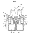
- FIG. 1 is a cross-sectional view showing an example of an air conditioner for a vehicle.
- An air conditioner for a vehicle is configured to include an air conditioning case 10 provided with vents 11, 12, and 13 of which the opening degree is controlled by each of the doors 11d, 12d, and 13d; a blowing part 14 connected to an inlet of the air conditioning case 10 to blow external air; an evaporator E and a heater core H mounted in the air conditioning case 10; and a temperature door 15 controlling an opening degree of a cold air passage P1 and a hot air passage P2 of the air conditioning case 10.
- the air conditioner is an apparatus that performs a heat exchange with introduced external air so as to be at an optimal temperature and then distributes the air in several directions inside a vehicle.
- external air including various harmful substances such as dust, smoke gases, and the like, generated from a road due to environmental pollution
- the external air passes through the air conditioner and is then delivered to the inside of a vehicle indoor as it is.
- bacterial foreign materials such as mildew accumulate in the air conditioner, and the like, exist, these bacterial foreign materials may also be delivered to the inside of a vehicle.
- FIG. 1 Japanese Utility Model Laid-Open Publication No. 1994-032126 (Entitled: Apparatus for generating perfume for vehicles) is shown in FIG. 1 .
- An apparatus 1 for generating perfume for vehicles is applied to an air conditioner 2 for vehicles that includes a blowing duct 3 of which the opening degree is controlled by each door 12d, 13d, and 14d and guiding blowing air to each vent 12, 13, and 14 communicating with a vehicle indoor; a blowing part 4 mounted in the blowing duct 3; an evaporator 5 and a heat core 6 mounted in the blowing duct 3 and is configured to include a first communicating passage 18 connected at a downstream side of the blowing part 4 in the blowing duct 3; a second communicating passage 19 connected at a downstream side of the heater core 6; perfume containers 15, 16, and 17 mounted between the first communicating passage 18 and the second communicating passage 19 and having perfume received therein; and a control part 25 including control valves 21, 22, and 24 to control a supply of perfume component within the perfume containers 15, 16, and 17.
- the apparatus for generating perfume for vehicles can supply a mixture of the perfume component jetted into the blowing duct and air supplied through the blowing part.
- the apparatus for generating perfume for vehicles is configured to use the plurality of control valves and therefore, cannot easily perform a control.
- An exemplary embodiment of the present invention is directed to providing an apparatus for generating perfume for vehicles capable of simplifying a configuration and increasing sealing ability to stably control perfume, by easily controlling a flow of air passing through a first perfume generating part and a second perfume generating part using a single rotating shaft.
- an exemplary embodiment of the present invention is directed to providing an apparatus for generating perfume for vehicles capable of opening and closing a first door to a fourth door by a rotation of a rotating shaft.
- an exemplary embodiment of the present invention is directed to providing an apparatus for generating perfume for vehicles capable of increasing sealing ability, by including a door seating member, mounting a first sealing member on a surface on which a first door to a fourth door contact the door seating member, and mounting a second sealing member under a first channel to a fourth channel.
- an exemplary embodiment of the present invention is directed to providing an apparatus for generating perfume for vehicles capable of smoothing an introduced flow of air introduced through an inlet pipe and a discharged flow of air discharged through an outlet pipe and reducing a pressure drop of air, by mounting the inlet pipe and the outlet pipe on a corresponding cover above a rotating shaft and forming a plate-shaped guide member on a rotating shaft.
- an exemplary embodiment of the present invention is directed to providing an apparatus for generating perfume for vehicles capable of smoothing an introduced flow of air by reducing a pressure drop of air introduced through an inlet pipe, reducing a pressure drop of air, and reducing a difference in intensity of two perfumes perfumed through a first perfume generating part and a second perfume generating part, and increasing the overall air volume, by mounting an inlet pipe over a cover.
- an exemplary embodiment of the present invention is directed to providing an apparatus for generating perfume for vehicles capable of easily changing a type of perfume and easily replacing perfume according to a user's taste, by detachably forming a lower portion of a body due to a lower cover and forming a first perfume generating part and a second perfume generating part in a cartridge form.
- an apparatus 1000 for generating perfume for vehicles includes: a body 100 having a first perfume generating part 110 and a second perfume generating part 120 embedded in parallel therein, an upper one portion of the first perfume generating part 110 is provided with a first hole 111 and the upper other portion thereof is provided with a second hole 112 and an upper one portion of the second perfume generating part 120 is provided with a third hole 121 and a fourth hole 120; an air channel forming part 130 including a first channel 131 communicating with a first hole 111 of the first perfume generating part 110, a second channel 132 communicating with a second hole 111 of the first perfume generating part 110, a third channel 133 communicating with a third hole 121 of the second perfume generating part 120, and a fourth channel 134 communicating with a fourth hole 122 of the second perfume generating part 120; an opening and closing means 200 including a first door 210 to a fourth door 240 each opening the first channel 131 to the fourth channel 134 and a single rotating shaft 250 controlling an opening and closing
- the apparatus 1000 for generating perfume for vehicles may further include: a cover 400 fastened with the body 100 and including a first space part 401 communicating the first channel 131 and the third channel 133 and a second space part 402 communicating with the second channel 132 and the fourth channel 134 partitioned thereon.
- the cover 400 may be provided with an inlet pipe 510 and an outlet pipe 520 each connected to the first space part 401 and the second space part 402 so as to introduce and discharge air.
- the air channel forming part 130 may be provided with an inclined part 141 to be inclined between the first perfume generating part 110 and the second perfume generating part 120 as upper sections of the first channel 131 to the fourth channel 134 go downwardly.
- the air channel forming part 130 may be protrudedly provided with a partition part 142 partitioning a space in which the first space part 401 and the second space part 402 communicate with each other, upwardly from the inclined part 141.
- the opening and closing means 200 may be provided with a door seating member 260 that is mounted between the air channel forming part 130 and the first door 210 to the fourth door 240 so as to correspond to an upper portion of the air channel forming part 130 provided with the inclined part 141 and the partition part 142 and may be provided with a first communicating hole 261 communicating with the first channel 131, a second communicating hole 262 communicating with the second channel 132, a third communication hole 263 communicating with the third channel 133, and a fourth communicating hole 264 communicating with the fourth channel 134.
- the door seating member 260 may be formed of a rubber material.
- a plate-shaped first sealing member 202 may be integrally formed on a surface on which the first door 210 to the fourth door 240 each contact the door seating member 260.
- the first door 210 to the fourth door 240 are interposed with a spring 201 maintained to open the first channel 131 to the fourth channel 134.
- the opening and closing means 200 may open and close the first door 210 to the fourth door 240 by the rotation of the rotating shaft 250 by forming a first opening and closing part 251 simultaneously closing the first door 210 and the third door 230 and a second opening and closing part 252 simultaneously closing the second door 220 to the fourth door 240 each on the rotating shaft 250 in parallel in a fan shape.
- the spring 201 may be maintained to close the first channel 131 to the fourth channel 134 and the opening and closing means 200 may include a connection member 204 connecting the rotating shaft 250 with the first door 210 to the fourth door 240 to open and close the first door 210 to the fourth door 240 by the rotation of the rotating shaft 250.
- the first opening and closing part 251 simultaneously closing the first door 210 and the third door 230 and the second opening and closing part 252 simultaneously closing the second door 220 to the fourth door 240 may be each formed on the rotating shaft 250 in parallel in a fan shape.
- the first door 210 to the fourth door 240 may be protrudedly provided with guide parts 203 guiding a movement of the first opening and closing part 251 or the second opening and closing part 252 according to the rotation of the rotating shaft 250.
- the inlet pipe 510 may be located at a center of the first space part 401 corresponding to an upper portion of the rotating shaft 250.
- the outlet pipe 520 may be formed on a surface adjacent to the second channel 132 of the second space part 402 in a side of the cover 400, and the inlet pipe 510 may be formed to be smaller than the outlet pipe 520.
- the outlet pipe 520 may be located at a center of the second space part 402 corresponding to the upper portion of the rotating shaft 250, and the inlet pipe 510 and the outlet pipe 520 may be formed at the same size.
- the opening and closing means 200 may be provided with a pair of guide members 253 in a plate shape protruded to both sides of the rotating shaft 250 corresponding to the inlet pipe 510 or the outlet pipe 520 so as to guide the flow of air introduced from the inlet pipe 510 or air discharged to the outlet pipe 520.
- the body 100 may have an opened lower portion and the first perfume generating part 110 and the second perfume generating part 120 may be replaceably formed in a cartridge form through the opened lower portion of the body 100.
- the apparatus 1000 for generating perfume for vehicles may further include: second sealing members 101 formed on each of the lower portions of the first channel 131 to the fourth channel 134 contacting the first hole 111 to the fourth hole 122 of the air channel forming part 130.
- FIG. 1 is a diagram showing an air conditioner for a vehicle according to the related art.
- FIGS. 2 to 5 are a perspective view, an exploded perspective view, a cross-sectional view taken along AA', and a cross-sectional view taken along BB' of an apparatus for generating perfume for vehicles according to an exemplary embodiment of the present invention.
- FIG. 6 is a diagram showing an opening and closing means of an apparatus for generating perfume for vehicles according another exemplary embodiment of the present invention.
- FIG. 7A is a cross-sectional view for describing the operation of the opening and closing means.
- FIG. 7B is a diagram showing the flow of air in the state of FIG. 7A .
- FIG. 8A is a cross-sectional view for describing the operation of the opening and closing means.
- FIG. 8B is a diagram showing the flow of air in the state of FIG. 8A .
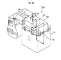
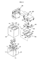
- FIGS. 9 to 11 are an exploded perspective view of an apparatus for generating perfume for vehicles according to another exemplary embodiment of the present invention and a diagram showing an operation thereof.
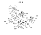
- FIG. 12 is a diagram showing an opening and closing means of an apparatus for generating perfume for vehicles according to another exemplary embodiment of the present invention.
- FIG. 13 is a diagram showing an apparatus for generating perfume for vehicles according another exemplary embodiment of the present invention.
- FIGS. 14 and 15 are a partially exploded perspective view and a cross-sectional view of an apparatus for generating perfume for vehicles according to the present invention.
- the apparatus 1000 for generating perfume for vehicles is configured to include a body 100, an air channel forming part 130, an opening and closing means 200, a driving means 300, a cover 400, an inlet pipe 510, and an outlet pipe 520.
- the body 100 is a basic body 100 forming the apparatus 1000 for generating perfume for vehicles according to the exemplary embodiment of the present invention and includes a first perfume generating part 110 and a second perfume generating part 120 emanating perfume embedded therein.
- the first perfume generating part 110 and the second perfume generating part 120 are extended in a horizontal direction and are mounted in parallel to form two columns.
- an upper one portion of the first perfume generating part 110 is provided with a first hole 111 and the upper other portion thereof is provided with a second hole 112 and the upper one side of the second perfume generating part 120 is provided with a third hole 121 and the upper other portion thereof is provided with a fourth hole 122.
- the first hole 111 and the second hole 112 introduces air into the first perfume generating part 110 or discharges internal air to the outside and the third hole 121 and the fourth hole 122 introduces air into the second perfume generating part 120 or discharges the internal air to the outside.
- the first perfume generating part 110 and the second perfume generating part 120 are located so that the first hole 111 and the third hole 121 are symmetrical with the second hole 112 and the fourth hole 122.
- the air channel forming part 130 is formed above a portion in which the first perfume generating part 110 and the second perfume generating part 120 are mounted and is configured to include a first channel 131 communicating with the first hole 111 of the first perfume generating part 110, a second channel 132 communicating with the second hole 112 of the first perfume generating part 110, a third channel 133 communicating with the third hole 121 of the second perfume generating part 120, and a fourth channel 134 communicating with the fourth hole 122 of the second perfume generating part 120.
- the air channel forming part 130 forms the first channel 131 to the fourth channel 134 so as to have an independent flow without mixing air supplied to the first perfume generating part 110, air discharged from the first perfume generating part 110, air supplied to the second perfume generating part 120, and air discharged from the second perfume generating part 120 with each other.
- the body 100 may have a form in which the air channel forming part 130 is integrally formed therein and forms the air channel forming part 130 so as to save costs and can be changed in a design in various forms including a space in which the first perfume generating part 110 and the second perfume generating part 120 are embedded.
- the opening and closing means 200 is a means that includes a first door 210 to a fourth door 240 each opening and closing the first channel 131 to the fourth channel 134 and a single rotating shaft 250 controlling the opening and closing of the first door 210 to the fourth door 240 and controls the operation of the first door 210 to the fourth door 240 by the operation of the rotating shaft 250 and controls the flow of air according to the opening and closing of the first door 210 to the fourth door 240.
- the first door 210 opens and closes the first channel 131
- the second door 220 opens and closes the second channel 132
- the third door 230 opens and closes the third channel 133
- the fourth door 240 opens and closes the fourth channel 134
- the first door 210 to the fourth door 240 are controlled by the operation of the rotating shaft 250.
- the exemplary embodiment of the present invention controls the operation of the first door 210 to the fourth door 240 using the single rotating shaft 250, thereby making it possible to save costs and improve productivity with a simple configuration.
- the opening and closing means 200 may be implemented in various forms using the single rotating shaft 250 and the detailed form thereof will be again described below.
- the driving means 300 is a means that is connected to the rotating shaft 250 of the opening and closing means 200 to drive the rotating shaft 250.
- a means such as an actuator may be used.
- the cover 400 is fastened with the body 100 and is partitioned into a first space part 401 communicating with the first channel 131 and the third channel 133 and a second space part 402 communicating with the second channel 132 and the fourth channel 134.
- first space part 401 and the second space part 402 are formed so that the cover 400 form may partition two spaces or have a baffle 40 formed therein.
- the drawing shows an example in which the baffle 420 is formed in the cover 400.
- the cover 400 seals the upper portion of the body 100 and is provided with the first space part 401 communicating with the first hole 111 of the first perfume generating part 110 and the third hole 121 of the second perfume generating part 120 and the second space part 402 communicating with the second hole 112 of the first perfume generating part 110 and the fourth hole 122 of the second perfume generating part 120.
- the first space part 401 and the second space part 402 of the cover 400 each are provided with an inlet pipe 510 into which air is introduced and an outlet pipe 520 from which air is discharged.
- the first space part 401 connected to the inlet pipe 510 is introduced with air such that the first door 210 and the third door 230 control the flow of air supplied to the first perfume generating part 110 or the second perfume generating part 120 and the outlet pipe 520 is connected to the second space part 402 to discharge air.
- the inlet pipe 510 and the outlet pipe 520 each communicate with the first space part 401 and the second space part 402, they may be formed at various locations of the cover 400.
- FIGS. 2 to 11 show the apparatus 1000 for generating perfume for vehicles according to the exemplary embodiment of the present invention in which the inlet pipe 510 is formed at the center of the first space part 401 of the upper portion of the cover 400 and the outlet pipe 520 is formed at a surface adjacent to the second channel 132 of the second space part 402 in the side of the cover 400.
- the inlet pipe 510 is formed on the upper portion of the cover 400 and is located at the central area of the first space part 401, such that the air introduced through the inlet pipe 510 may be smoothly guided to the first channel 131 associated with the first perfume generating part 110 or the second channel 132 associated with the second perfume generating part 120.
- the central area of the first space part 401 is a location corresponding to the upper portion of the rotating shaft 250.
- the apparatus 1000 for generating perfume for vehicles may have an advantage in that the inlet pipe 510 is located at the central area of the first space part 401 such that the air may be moved to the first perfume generating part 110 or the second perfume generating part 120 by the operation of the first door 210 or the third door 230 according to the control of the rotating shaft 250.
- a size of the inlet pipe 510 may be formed to be smaller than that of the outlet pipe 520 to reduce the pressure drop of air.
- the drawings show that the body 100 is protruded outwardly downwardly and the protrude portion of the body 100 is locked to the lower portion of the cover 400, which is only one exemplary embodiment. Therefore, the body 100 and the lower portion of the cover 400 may be fixed to each other by various fastening methods.
- the apparatus 1000 for generating perfume for vehicles it is preferable to form an inclined part 141 on the upper portion of the air channel forming part 130 so as to easily control the opening and closing by the single rotating shaft 250.
- the upper portions of the first channel 131 to the fourth channel 134 are provided with inclined parts 141 and the air channel forming part 130 is formed to be inclined between the first perfume generating part 110 and the second perfume generating part 120 as a section of the inclined part 141 goes downwardly (see FIGS. 4 and 5 ).
- the inclined part 141 of the air channel forming part 130 is formed to be inclined toward a portion between the first perfume generating part 110 and the second perfume generating part 120 as it goes downwardly and thus, is formed to an appropriate "V"-letter shape like a section in the AA' direction.
- the partitioning part 142 partitioning the space in which the first space part 401 and second space part 402 communicate with each other between the upper portion (the upper area of the inclined part 141 of the air channel forming part 130) of the body 100 and the cover 400 is protruded upwardly from the air channel forming part 130 to partition the introduced air and the discharged air.
- the opening and closing means 200 may be formed in the space in which the inclined part 141 and the partition part 142 of the air channel forming part 130 are formed and may further include a door seating member 260 so as to increase the sealing ability.
- the door seating member 260 is mounted between the air channel forming part 130 and the first door 210 to the fourth door 240 so as to correspond to the upper portion of the air channel forming part 130 provided with the inclined part 141 and the partition part 142 of the body 100 and is provided with a first communicating hole 261 communicating with the first channel 131, a second communicating hole 262 communicating with the second channel 132, a third communication hole 263 communicating with the third channel 133, and a fourth communicating hole 264 communicating with the fourth channel 134.
- the door seating member 260 may be preferably formed of a rubber material and is preferably extended between the upper portion of the body 100 and the lower portion of the cover 400 to more increase the sealing ability.
- the door seating member 260, the body 100, or the cover 400 is formed so as to be connected with the driving means 300 by protruding a predetermined area of the rotating shaft 250 to the outside.
- the opening and closing means 200 is formed so that the first door 210 to the fourth door 240 open and close the first channel 131 to the fourth channel 134 and the first door 210 to the fourth door 240 are operated together by the rotation of the rotating shaft 250.
- the opening and closing means 200 may be formed to have various forms. Meanwhile, FIGS. 2 to 8 show an example in which the opening and closing means 200 are formed to maintain the opened state by a spring 201 opening the first channel 131 to the fourth channel 134 and a first opening and closing part 251 and a second opening and closing part 252 in a fan shape are formed on the rotating shaft 250.
- FIGS. 9 to 12 show an example in which the spring 201 maintained to close the first channel 131 to the fourth channel 134 is interposed and the rotating shaft 250 is connected with the first door 210 to the fourth door 240 by a connection member 204.
- FIGS. 2 to 8 First, the form shown in FIGS. 2 to 8 will be described.
- the first door 210 to the fourth door 240 is formed to maintain the opened state by the spring 201 maintained to open the first channel 131 to the fourth channel 134.
- the opening and closing means 200 is formed so that the first door 210 to the fourth door 240 is formed to close the first channel 131 to the fourth channel 134 in an opposite direction to the elasticity of the spring 201 and is opened and closed by the rotation of the rotating shaft 250.
- the opening and closing means 200 opens and closes the first door 210 to the fourth door 240 by the rotation of the rotating shaft 250 by forming the first opening and closing part 251 that can simultaneously close the first door 210 and the third door 230 and the second opening and closing part 252 that can simultaneously close the second door 220 to the fourth door 240 on the rotating shaft 250 in a fan shape.
- the first opening and closing part 251 and the second opening and closing part 252 are formed in parallel with each other while being spaced apart from each other in a length direction of the rotating shaft 250 and are operated together with the rotating shaft 250 and when the first opening and closing part 251 opens the first door 210 by the rotation of the rotating shaft 250, the second opening and closing part 252 also opens the second door 220 and closes the third door 230 and the fourth door 240.
- the second opening and closing part 252 when the first opening and closing part 251 opens the third door 230 by the rotation of the rotating shaft 250, the second opening and closing part 252 also opens the fourth door 240 and closes the first door 210 and the second door 220.
- the first opening and closing part 251 and the second opening and closing part 252 are formed to have the same form and when the first opening and closing part 251 and the second opening and closing part 252 are assembled with the body 100, have a fan shape having a size enough that the first opening and closing part 251 can simultaneously close the first door 210 and the third door 230 and the second opening and closing part 252 can simultaneously close the second door 220 and the fourth door 240.
- the first door 210 to the fourth door 240 are formed with guide parts 203 having protruded both sides in an area in which the first opening and closing part 251 or the second opening and closing part 252 move by the rotation of the rotating shaft 250 so as to guide the movement of the first opening and closing part 251 or the second opening and closing part 252 (see FIG. 6 ).
- FIGS. 9 to 12 show an example in which the opening and closing means 200 opens and closes the first door 210 to the fourth door 240 by the rotation of the rotating shaft 250 by connecting the rotating shaft 250 with the first door 210 to the fourth door 240 by the connection member 204.
- the rotating shaft 250 is provided with the first opening and closing part 251 that can simultaneously close the first door 210 and the third door 230 in the fan shape and the second opening and closing part 252 that can simultaneously close the second door 220 and the fourth door 240 in a fan shape so as to increase the sealing ability of the first door 210 to the fourth door 240 and the spring 201 maintained to close the first channel 131 to the fourth channel 134 is interposed between the first door 210 to the fourth door 240.
- the first opening and closing part 251 and the second opening and closing part 252 are the same as the form shown in FIGS. 2 to 8 . Further, the first door 210 to the fourth door 240 may also be further provided with guide parts 203 (see FIG. 12 ).
- the apparatus 1000 for generating perfume for vehicles according to the present invention can easily change a type of perfume according to the user's taste and easily replace perfume as the lower portion of the body 100 is opened and the first perfume generating part 110 and the second perfume generation part 120 are formed in a cartridge form.
- the air channel forming part 130 is to more increase the sealing ability by mounting the second sealing members 101 on each of the lower portions of the first channel 131 to the fourth channel 134 contacting the first hole 111 to the fourth hole 122. (the second sealing member 101 is provided between the first channel 131 to the fourth channel 134 through which the first hole 111 and the second hole 112 of the first perfume generating part 110 communicate with the third hole 121 and the fourth hole 122 of the second perfume generating part 120).
- FIGS. 7A to 8B are diagrams showing the operation of the apparatus 1000 for generating perfume for vehicles according to the exemplary embodiment of the present invention.
- FIG. 7A is a cross-sectional view for describing the operation of the opening and closing means 200 and FIG. 7B shows the flow of air in the state of FIG. 7A .
- the apparatus 1000 for generating perfume for vehicles according to the exemplary embodiment of the present invention shown in FIGS. 7A and 7B show an example in which the rotating shaft 250 is rotated counterclockwise based on the fixed position of the cross-sectional view shown in FIGS. 4 and 5 to open the first door 210 and the second door 220 and close the third door 230 and the fourth door 240.
- the air introduced into the first space part 401 of the cover 400 through the inlet pipe 510 moves to the first perfume generating part 110 through the first communicating hole 261 of the door seating member 260, the first channel 131 of the air channel forming part 130, and the first hole 111 as the first door 210 and the second door 220 are opened and again moves to the second space part 402 of the cover 400 along the second hole 112, the second channel 132 of the air channel forming part 130, and the second communicating hole 262 of the door seating member 260 and is discharged through the outlet pipe 520.
- the apparatus 1000 for generating perfume for vehicles according to the exemplary embodiment of the present invention shown in FIGS. 8A and 8B show an example in which the rotating shaft 250 is rotated clockwise based on the fixed position of the cross-sectional view shown in FIGS. 4 and 5 to close the first door 210 and the second door 220 and open the third door 230 and the fourth door 240.
- the air introduced thereinto is discharged to the outside through the second perfume generating part 120.
- the air introduced into the first space part 401 of the cover 400 through the inlet pipe 510 moves to the second perfume generating part 121 through the third communicating hole 263 of the door seating member 260, the third channel 133 of the air channel forming part 130, and the third hole 121 as the third door 230 and the fourth door 240 are opened and again moves to the second space part 402 of the cover 400 along the fourth hole 122, the fourth channel 134 of the air channel forming part 130, and the fourth communicating hole 264 of the door seating member 260 and is discharged through the outlet pipe 520.
- FIG. 13 an example in which the inlet pipe 510 and the outlet pipe 520 are located above of the upper cover 400 and are each located in the central areas of the first space parts 401 and 402 is shown.
- the rotating shaft 250 is one and is extended over the first space part 401 and the second space part 402 and therefore, the central area of the first space part 401 and the second space part 402 correspond to the upper portion of the rotating shaft 250.
- inlet pipe 510 and the outlet pipe 520 it is preferable to form the inlet pipe 510 and the outlet pipe 520 at the same size.
- the remaining component other than the formation location of the outlet pipe 520 and the size of the inlet pipe 510 and the outlet pipe 520 may be applied to the exemplary embodiment of various forms shown in FIGS. 2 to 12 and may be a form shown in FIGS. 14 and 15 .
- FIGS. 14 and 15 is the same as the form shown in FIG. 6 but shows the example in which the rotating shaft 250 of the opening and closing means 200 is further provided with guide members 253.
- the guide member 253 is formed in pair in a plate shape protruded to both sides of the rotating shaft 250 corresponding to the inlet pipe 510 or the outlet pipe 520 and the flow of air introduced from the inlet pipe 510 or the flow of air discharged to the output pipe 520 are guided by the rotation of the rotating shaft 250.
- the inlet pipe 510 or the outlet pipe 520 may be preferably formed above the rotating shaft 250 so as to more increase the guide effect of the flow of air by the guide member.
- the guide members 253 may be each formed on both sides of one of the first opening and closing part 251 and the second opening and closing part 252 when the opening and closing means 200 is provided with the first opening and closing part 251 and the second opening and closing part 252 or may each be formed on both sides of both of the first opening and closing part 251 and the second opening and closing part 252.
- both sides of the first opening part 251 and the second opening part 252 mean a radius portion in a section having a fan shape.
- the apparatus 1000 for generating perfume for vehicles includes the guide member 253 to guide the air introduced through the inlet pipe 510 and the air discharged through the outlet pipe 520, thereby more smoothing the flow of air.
- the apparatus 1000 for generating perfume for vehicles can reduce the air pressure drop by locate the inlet pipe 510 at the center of the first space part 401 of the upper cover 400, easily control the flow of air passing through the first perfume generating part 110 and the second perfume generating part 120 using the single rotating shaft 250, thereby simplifying the configuration and increasing the sealing ability to stably control perfume.
- the apparatus for generating perfume for vehicles can easily control the flow of air through the first perfume generating part and the second perfume generating part using the single rotating shaft, thereby simplifying the configuration and increasing the sealing ability to stably control the perfume.
- the apparatus for generating perfume for vehicles can open and close the first door to the fourth door by the rotation of the rotating shaft.
- the apparatus for generating perfume for vehicles can include the door seating member, mount the first sealing member on the surface on which the first door to the fourth door contact the door seating member, and mount the second sealing member under the first channel to the fourth channel, thereby increasing the sealing ability.
- the apparatus for generating perfume for vehicles can mount the inlet pipe and the outlet pipe on the corresponding cover above the rotating shaft and form the plate-shaped guide member on the rotating shaft, thereby smoothing the introduced flow of air introduced through the inlet pipe and the flow of air discharged through the outlet pipe and reducing the pressure drop of air.
- the apparatus for generating perfume for vehicles can mount the inlet pipe above the cover, thereby smoothing the introduced flow of air by reducing the pressure drop of air introduced through the inlet pipe, reducing the pressure drop of air, reducing the difference in intensity of two perfumes perfumed through the first perfume generating part and the second perfume generating part, and increasing the overall air volume.
- the apparatus for generating perfume for vehicles can detachably form the lower portion of the body due to the lower cover and form the first perfume generating part and the second perfume generating part in the cartridge form, thereby easily changing the type of perfume and easily replacing perfume according to a user's taste.
- the present invention is not limited to the above-mentioned exemplary embodiments, and may be variously applied, and may be variously modified without departing from the gist of the present invention claimed in the claims.
Landscapes
- Engineering & Computer Science (AREA)
- Mechanical Engineering (AREA)
- Disinfection, Sterilisation Or Deodorisation Of Air (AREA)
- Air-Conditioning For Vehicles (AREA)
Applications Claiming Priority (3)
| Application Number | Priority Date | Filing Date | Title |
|---|---|---|---|
| KR1020110089467A KR101435670B1 (ko) | 2011-09-05 | 2011-09-05 | 차량용 방향제 취출 장치 |
| KR1020110092377A KR101760305B1 (ko) | 2011-09-14 | 2011-09-14 | 차량용 방향제 취출 장치 |
| KR1020120000872A KR101353427B1 (ko) | 2012-01-04 | 2012-01-04 | 차량용 방향제 취출 장치 |
Publications (3)
| Publication Number | Publication Date |
|---|---|
| EP2565066A2 true EP2565066A2 (de) | 2013-03-06 |
| EP2565066A3 EP2565066A3 (de) | 2013-09-11 |
| EP2565066B1 EP2565066B1 (de) | 2016-04-13 |
Family
ID=46826206
Family Applications (1)
| Application Number | Title | Priority Date | Filing Date |
|---|---|---|---|
| EP12006190.8A Active EP2565066B1 (de) | 2011-09-05 | 2012-08-31 | Vorrichtung zur Erzeugung von Parfüm für Fahrzeuge |
Country Status (3)
| Country | Link |
|---|---|
| US (1) | US8932526B2 (de) |
| EP (1) | EP2565066B1 (de) |
| CN (1) | CN102975593B (de) |
Families Citing this family (4)
| Publication number | Priority date | Publication date | Assignee | Title |
|---|---|---|---|---|
| DE102015217250A1 (de) * | 2015-09-09 | 2017-03-09 | Mahle International Gmbh | Duftstoffabgabevorrichtung und eine Belüftungs-, Heizungs- oder Klimaanlage mit einer solchen Duftstoffabgabevorrichtung |
| JP6943171B2 (ja) * | 2017-12-19 | 2021-09-29 | トヨタ自動車株式会社 | 車両用芳香発生装置 |
| CN110103678B (zh) * | 2019-03-29 | 2019-11-19 | 金华东阳展堂生物科技有限公司 | 一种车载香水盒 |
| KR102918668B1 (ko) * | 2020-12-04 | 2026-01-28 | 한온시스템 주식회사 | 차량용 향 발생기 |
Citations (1)
| Publication number | Priority date | Publication date | Assignee | Title |
|---|---|---|---|---|
| JPH0632126U (ja) | 1992-10-02 | 1994-04-26 | 日本電装株式会社 | 車両用香り発生装置 |
Family Cites Families (11)
| Publication number | Priority date | Publication date | Assignee | Title |
|---|---|---|---|---|
| JPH02225125A (ja) * | 1988-11-24 | 1990-09-07 | Nippondenso Co Ltd | 香り発生器 |
| JPH0632126A (ja) | 1992-07-13 | 1994-02-08 | Toyota Motor Corp | 車輌用ダブルアーム式サスペンション |
| DE19530899C2 (de) | 1995-08-23 | 2003-08-21 | Bosch Gmbh Robert | Magnetventil, insbesondere für eine schlupfgeregelte, hydraulische Bremsanlage für Kraftfahrzeuge |
| US6015094A (en) * | 1997-05-09 | 2000-01-18 | Por; Sze Pik | Vehicle Perfume Dispenser |
| US6713024B1 (en) * | 1998-08-28 | 2004-03-30 | Aroma Technology Limited | Odor dispensing device and odor dispensing cartridge |
| CN101687054B (zh) * | 2007-07-03 | 2014-01-01 | 贝洱两合公司 | 用于汽车的空气清新装置 |
| DE102008032615A1 (de) * | 2008-07-11 | 2010-01-14 | Behr Gmbh & Co. Kg | Duftmittelvorratsvorrichtung |
| KR101549476B1 (ko) | 2009-07-06 | 2015-09-02 | 한온시스템 주식회사 | 차량용 방향제 발생장치 |
| US8931712B2 (en) * | 2009-02-05 | 2015-01-13 | Valeo Japan Co., Ltd. | Fragrance device for vehicle and sealing component used therein |
| JP5390877B2 (ja) | 2009-02-05 | 2014-01-15 | 株式会社ヴァレオジャパン | 車両用芳香装置 |
| FR2942175B1 (fr) * | 2009-02-17 | 2011-10-07 | Valeo Systemes Thermiques | Dispositif d'odorisation de l'habitacle d'un vehicule automobile |
-
2012
- 2012-08-30 US US13/599,192 patent/US8932526B2/en active Active
- 2012-08-31 EP EP12006190.8A patent/EP2565066B1/de active Active
- 2012-09-05 CN CN201210326065.6A patent/CN102975593B/zh active Active
Patent Citations (1)
| Publication number | Priority date | Publication date | Assignee | Title |
|---|---|---|---|---|
| JPH0632126U (ja) | 1992-10-02 | 1994-04-26 | 日本電装株式会社 | 車両用香り発生装置 |
Also Published As
| Publication number | Publication date |
|---|---|
| CN102975593A (zh) | 2013-03-20 |
| US20130056559A1 (en) | 2013-03-07 |
| US8932526B2 (en) | 2015-01-13 |
| CN102975593B (zh) | 2015-10-28 |
| EP2565066B1 (de) | 2016-04-13 |
| EP2565066A3 (de) | 2013-09-11 |
Similar Documents
| Publication | Publication Date | Title |
|---|---|---|
| CN102950989B (zh) | 车用空调 | |
| CN100526105C (zh) | 车用鼓风机 | |
| CN102645010B (zh) | 用于车辆的空调 | |
| US20060116064A1 (en) | Ceiling air-blowing device for a vehicle air conditioner | |
| JP2003002034A (ja) | 車両用空調装置 | |
| US7798207B2 (en) | Air conditioner with guide structure for vehicles | |
| EP2565066A2 (de) | Vorrichtung zur Erzeugung von Parfüm für Fahrzeuge | |
| US9694652B2 (en) | Vehicle rear console duct air flow | |
| US8544533B2 (en) | Vehicular air conditioner having two-layered air flow | |
| US20110048673A1 (en) | Air-conditioner for vehicle | |
| KR101207307B1 (ko) | 차량용 공조장치 | |
| KR101319437B1 (ko) | 차량용 공조장치 | |
| US20050098311A1 (en) | Air-conditioning unit | |
| KR101435670B1 (ko) | 차량용 방향제 취출 장치 | |
| EP2567841A2 (de) | Klimaanlage für ein Fahrzeug | |
| KR101436950B1 (ko) | 차량용 방향제 취출 장치 | |
| EP3121041A1 (de) | Klimaanlagensystem für ein fahrzeug | |
| KR20120018418A (ko) | 차량용 공조장치 | |
| KR101150468B1 (ko) | 지게차용 공기조화장치 | |
| JP2003034114A (ja) | 車両用空調装置 | |
| KR101760305B1 (ko) | 차량용 방향제 취출 장치 | |
| KR101309201B1 (ko) | 차량용 공조장치 | |
| KR20130066861A (ko) | 차량용 공조장치 | |
| US20070131407A1 (en) | Air conditioning apparatus | |
| JP2002307929A (ja) | 車両用空調装置 |
Legal Events
| Date | Code | Title | Description |
|---|---|---|---|
| PUAI | Public reference made under article 153(3) epc to a published international application that has entered the european phase |
Free format text: ORIGINAL CODE: 0009012 |
|
| 17P | Request for examination filed |
Effective date: 20120831 |
|
| AK | Designated contracting states |
Kind code of ref document: A2 Designated state(s): AL AT BE BG CH CY CZ DE DK EE ES FI FR GB GR HR HU IE IS IT LI LT LU LV MC MK MT NL NO PL PT RO RS SE SI SK SM TR |
|
| AX | Request for extension of the european patent |
Extension state: BA ME |
|
| PUAL | Search report despatched |
Free format text: ORIGINAL CODE: 0009013 |
|
| RAP1 | Party data changed (applicant data changed or rights of an application transferred) |
Owner name: HALLA VISTEON CLIMATE CONTROL CORP. |
|
| AK | Designated contracting states |
Kind code of ref document: A3 Designated state(s): AL AT BE BG CH CY CZ DE DK EE ES FI FR GB GR HR HU IE IS IT LI LT LU LV MC MK MT NL NO PL PT RO RS SE SI SK SM TR |
|
| AX | Request for extension of the european patent |
Extension state: BA ME |
|
| RIC1 | Information provided on ipc code assigned before grant |
Ipc: B60H 3/00 20060101AFI20130807BHEP |
|
| GRAP | Despatch of communication of intention to grant a patent |
Free format text: ORIGINAL CODE: EPIDOSNIGR1 |
|
| INTG | Intention to grant announced |
Effective date: 20151026 |
|
| RAP1 | Party data changed (applicant data changed or rights of an application transferred) |
Owner name: HANON SYSTEMS |
|
| GRAS | Grant fee paid |
Free format text: ORIGINAL CODE: EPIDOSNIGR3 |
|
| GRAA | (expected) grant |
Free format text: ORIGINAL CODE: 0009210 |
|
| AK | Designated contracting states |
Kind code of ref document: B1 Designated state(s): AL AT BE BG CH CY CZ DE DK EE ES FI FR GB GR HR HU IE IS IT LI LT LU LV MC MK MT NL NO PL PT RO RS SE SI SK SM TR |
|
| REG | Reference to a national code |
Ref country code: GB Ref legal event code: FG4D |
|
| REG | Reference to a national code |
Ref country code: AT Ref legal event code: REF Ref document number: 789708 Country of ref document: AT Kind code of ref document: T Effective date: 20160415 Ref country code: CH Ref legal event code: EP |
|
| REG | Reference to a national code |
Ref country code: IE Ref legal event code: FG4D |
|
| REG | Reference to a national code |
Ref country code: DE Ref legal event code: R096 Ref document number: 602012016942 Country of ref document: DE |
|
| REG | Reference to a national code |
Ref country code: LT Ref legal event code: MG4D |
|
| REG | Reference to a national code |
Ref country code: AT Ref legal event code: MK05 Ref document number: 789708 Country of ref document: AT Kind code of ref document: T Effective date: 20160413 |
|
| REG | Reference to a national code |
Ref country code: NL Ref legal event code: MP Effective date: 20160413 |
|
| PG25 | Lapsed in a contracting state [announced via postgrant information from national office to epo] |
Ref country code: FI Free format text: LAPSE BECAUSE OF FAILURE TO SUBMIT A TRANSLATION OF THE DESCRIPTION OR TO PAY THE FEE WITHIN THE PRESCRIBED TIME-LIMIT Effective date: 20160413 Ref country code: NL Free format text: LAPSE BECAUSE OF FAILURE TO SUBMIT A TRANSLATION OF THE DESCRIPTION OR TO PAY THE FEE WITHIN THE PRESCRIBED TIME-LIMIT Effective date: 20160413 Ref country code: LT Free format text: LAPSE BECAUSE OF FAILURE TO SUBMIT A TRANSLATION OF THE DESCRIPTION OR TO PAY THE FEE WITHIN THE PRESCRIBED TIME-LIMIT Effective date: 20160413 Ref country code: PL Free format text: LAPSE BECAUSE OF FAILURE TO SUBMIT A TRANSLATION OF THE DESCRIPTION OR TO PAY THE FEE WITHIN THE PRESCRIBED TIME-LIMIT Effective date: 20160413 Ref country code: NO Free format text: LAPSE BECAUSE OF FAILURE TO SUBMIT A TRANSLATION OF THE DESCRIPTION OR TO PAY THE FEE WITHIN THE PRESCRIBED TIME-LIMIT Effective date: 20160713 |
|
| PG25 | Lapsed in a contracting state [announced via postgrant information from national office to epo] |
Ref country code: HR Free format text: LAPSE BECAUSE OF FAILURE TO SUBMIT A TRANSLATION OF THE DESCRIPTION OR TO PAY THE FEE WITHIN THE PRESCRIBED TIME-LIMIT Effective date: 20160413 Ref country code: LV Free format text: LAPSE BECAUSE OF FAILURE TO SUBMIT A TRANSLATION OF THE DESCRIPTION OR TO PAY THE FEE WITHIN THE PRESCRIBED TIME-LIMIT Effective date: 20160413 Ref country code: RS Free format text: LAPSE BECAUSE OF FAILURE TO SUBMIT A TRANSLATION OF THE DESCRIPTION OR TO PAY THE FEE WITHIN THE PRESCRIBED TIME-LIMIT Effective date: 20160413 Ref country code: PT Free format text: LAPSE BECAUSE OF FAILURE TO SUBMIT A TRANSLATION OF THE DESCRIPTION OR TO PAY THE FEE WITHIN THE PRESCRIBED TIME-LIMIT Effective date: 20160816 Ref country code: ES Free format text: LAPSE BECAUSE OF FAILURE TO SUBMIT A TRANSLATION OF THE DESCRIPTION OR TO PAY THE FEE WITHIN THE PRESCRIBED TIME-LIMIT Effective date: 20160413 Ref country code: GR Free format text: LAPSE BECAUSE OF FAILURE TO SUBMIT A TRANSLATION OF THE DESCRIPTION OR TO PAY THE FEE WITHIN THE PRESCRIBED TIME-LIMIT Effective date: 20160714 Ref country code: AT Free format text: LAPSE BECAUSE OF FAILURE TO SUBMIT A TRANSLATION OF THE DESCRIPTION OR TO PAY THE FEE WITHIN THE PRESCRIBED TIME-LIMIT Effective date: 20160413 Ref country code: SE Free format text: LAPSE BECAUSE OF FAILURE TO SUBMIT A TRANSLATION OF THE DESCRIPTION OR TO PAY THE FEE WITHIN THE PRESCRIBED TIME-LIMIT Effective date: 20160413 |
|
| PG25 | Lapsed in a contracting state [announced via postgrant information from national office to epo] |
Ref country code: IT Free format text: LAPSE BECAUSE OF FAILURE TO SUBMIT A TRANSLATION OF THE DESCRIPTION OR TO PAY THE FEE WITHIN THE PRESCRIBED TIME-LIMIT Effective date: 20160413 Ref country code: BE Free format text: LAPSE BECAUSE OF FAILURE TO SUBMIT A TRANSLATION OF THE DESCRIPTION OR TO PAY THE FEE WITHIN THE PRESCRIBED TIME-LIMIT Effective date: 20160413 |
|
| REG | Reference to a national code |
Ref country code: DE Ref legal event code: R097 Ref document number: 602012016942 Country of ref document: DE |
|
| PG25 | Lapsed in a contracting state [announced via postgrant information from national office to epo] |
Ref country code: SK Free format text: LAPSE BECAUSE OF FAILURE TO SUBMIT A TRANSLATION OF THE DESCRIPTION OR TO PAY THE FEE WITHIN THE PRESCRIBED TIME-LIMIT Effective date: 20160413 Ref country code: EE Free format text: LAPSE BECAUSE OF FAILURE TO SUBMIT A TRANSLATION OF THE DESCRIPTION OR TO PAY THE FEE WITHIN THE PRESCRIBED TIME-LIMIT Effective date: 20160413 Ref country code: RO Free format text: LAPSE BECAUSE OF FAILURE TO SUBMIT A TRANSLATION OF THE DESCRIPTION OR TO PAY THE FEE WITHIN THE PRESCRIBED TIME-LIMIT Effective date: 20160413 Ref country code: DK Free format text: LAPSE BECAUSE OF FAILURE TO SUBMIT A TRANSLATION OF THE DESCRIPTION OR TO PAY THE FEE WITHIN THE PRESCRIBED TIME-LIMIT Effective date: 20160413 Ref country code: CZ Free format text: LAPSE BECAUSE OF FAILURE TO SUBMIT A TRANSLATION OF THE DESCRIPTION OR TO PAY THE FEE WITHIN THE PRESCRIBED TIME-LIMIT Effective date: 20160413 |
|
| PLBE | No opposition filed within time limit |
Free format text: ORIGINAL CODE: 0009261 |
|
| STAA | Information on the status of an ep patent application or granted ep patent |
Free format text: STATUS: NO OPPOSITION FILED WITHIN TIME LIMIT |
|
| PG25 | Lapsed in a contracting state [announced via postgrant information from national office to epo] |
Ref country code: SM Free format text: LAPSE BECAUSE OF FAILURE TO SUBMIT A TRANSLATION OF THE DESCRIPTION OR TO PAY THE FEE WITHIN THE PRESCRIBED TIME-LIMIT Effective date: 20160413 |
|
| 26N | No opposition filed |
Effective date: 20170116 |
|
| PG25 | Lapsed in a contracting state [announced via postgrant information from national office to epo] |
Ref country code: MC Free format text: LAPSE BECAUSE OF FAILURE TO SUBMIT A TRANSLATION OF THE DESCRIPTION OR TO PAY THE FEE WITHIN THE PRESCRIBED TIME-LIMIT Effective date: 20160413 |
|
| REG | Reference to a national code |
Ref country code: CH Ref legal event code: PL |
|
| GBPC | Gb: european patent ceased through non-payment of renewal fee |
Effective date: 20160831 |
|
| PG25 | Lapsed in a contracting state [announced via postgrant information from national office to epo] |
Ref country code: CH Free format text: LAPSE BECAUSE OF NON-PAYMENT OF DUE FEES Effective date: 20160831 Ref country code: LI Free format text: LAPSE BECAUSE OF NON-PAYMENT OF DUE FEES Effective date: 20160831 |
|
| REG | Reference to a national code |
Ref country code: FR Ref legal event code: ST Effective date: 20170428 |
|
| PG25 | Lapsed in a contracting state [announced via postgrant information from national office to epo] |
Ref country code: SI Free format text: LAPSE BECAUSE OF FAILURE TO SUBMIT A TRANSLATION OF THE DESCRIPTION OR TO PAY THE FEE WITHIN THE PRESCRIBED TIME-LIMIT Effective date: 20160413 |
|
| REG | Reference to a national code |
Ref country code: IE Ref legal event code: MM4A |
|
| PG25 | Lapsed in a contracting state [announced via postgrant information from national office to epo] |
Ref country code: IE Free format text: LAPSE BECAUSE OF NON-PAYMENT OF DUE FEES Effective date: 20160831 Ref country code: FR Free format text: LAPSE BECAUSE OF NON-PAYMENT OF DUE FEES Effective date: 20160831 Ref country code: GB Free format text: LAPSE BECAUSE OF NON-PAYMENT OF DUE FEES Effective date: 20160831 |
|
| PG25 | Lapsed in a contracting state [announced via postgrant information from national office to epo] |
Ref country code: LU Free format text: LAPSE BECAUSE OF NON-PAYMENT OF DUE FEES Effective date: 20160831 |
|
| PG25 | Lapsed in a contracting state [announced via postgrant information from national office to epo] |
Ref country code: HU Free format text: LAPSE BECAUSE OF FAILURE TO SUBMIT A TRANSLATION OF THE DESCRIPTION OR TO PAY THE FEE WITHIN THE PRESCRIBED TIME-LIMIT; INVALID AB INITIO Effective date: 20120831 Ref country code: CY Free format text: LAPSE BECAUSE OF FAILURE TO SUBMIT A TRANSLATION OF THE DESCRIPTION OR TO PAY THE FEE WITHIN THE PRESCRIBED TIME-LIMIT Effective date: 20160413 |
|
| PG25 | Lapsed in a contracting state [announced via postgrant information from national office to epo] |
Ref country code: MK Free format text: LAPSE BECAUSE OF FAILURE TO SUBMIT A TRANSLATION OF THE DESCRIPTION OR TO PAY THE FEE WITHIN THE PRESCRIBED TIME-LIMIT Effective date: 20160413 Ref country code: MT Free format text: LAPSE BECAUSE OF NON-PAYMENT OF DUE FEES Effective date: 20160831 Ref country code: TR Free format text: LAPSE BECAUSE OF FAILURE TO SUBMIT A TRANSLATION OF THE DESCRIPTION OR TO PAY THE FEE WITHIN THE PRESCRIBED TIME-LIMIT Effective date: 20160413 Ref country code: IS Free format text: LAPSE BECAUSE OF FAILURE TO SUBMIT A TRANSLATION OF THE DESCRIPTION OR TO PAY THE FEE WITHIN THE PRESCRIBED TIME-LIMIT Effective date: 20160413 |
|
| PG25 | Lapsed in a contracting state [announced via postgrant information from national office to epo] |
Ref country code: BG Free format text: LAPSE BECAUSE OF FAILURE TO SUBMIT A TRANSLATION OF THE DESCRIPTION OR TO PAY THE FEE WITHIN THE PRESCRIBED TIME-LIMIT Effective date: 20160413 |
|
| PG25 | Lapsed in a contracting state [announced via postgrant information from national office to epo] |
Ref country code: AL Free format text: LAPSE BECAUSE OF FAILURE TO SUBMIT A TRANSLATION OF THE DESCRIPTION OR TO PAY THE FEE WITHIN THE PRESCRIBED TIME-LIMIT Effective date: 20160413 |
|
| P01 | Opt-out of the competence of the unified patent court (upc) registered |
Effective date: 20230615 |
|
| PGFP | Annual fee paid to national office [announced via postgrant information from national office to epo] |
Ref country code: DE Payment date: 20250708 Year of fee payment: 14 |