EP2562122A1 - Rollenführung - Google Patents
Rollenführung Download PDFInfo
- Publication number
- EP2562122A1 EP2562122A1 EP12004770A EP12004770A EP2562122A1 EP 2562122 A1 EP2562122 A1 EP 2562122A1 EP 12004770 A EP12004770 A EP 12004770A EP 12004770 A EP12004770 A EP 12004770A EP 2562122 A1 EP2562122 A1 EP 2562122A1
- Authority
- EP
- European Patent Office
- Prior art keywords
- guide
- roller
- joint
- web
- rollers
- Prior art date
- Legal status (The legal status is an assumption and is not a legal conclusion. Google has not performed a legal analysis and makes no representation as to the accuracy of the status listed.)
- Granted
Links
- 238000010276 construction Methods 0.000 description 3
- 238000009435 building construction Methods 0.000 description 1
- 239000002131 composite material Substances 0.000 description 1
- 239000000463 material Substances 0.000 description 1
- 239000002184 metal Substances 0.000 description 1
- 238000009418 renovation Methods 0.000 description 1
Images


Classifications
-
- B—PERFORMING OPERATIONS; TRANSPORTING
- B66—HOISTING; LIFTING; HAULING
- B66B—ELEVATORS; ESCALATORS OR MOVING WALKWAYS
- B66B7/00—Other common features of elevators
- B66B7/02—Guideways; Guides
- B66B7/04—Riding means, e.g. Shoes, Rollers, between car and guiding means, e.g. rails, ropes
- B66B7/046—Rollers
-
- B—PERFORMING OPERATIONS; TRANSPORTING
- B66—HOISTING; LIFTING; HAULING
- B66B—ELEVATORS; ESCALATORS OR MOVING WALKWAYS
- B66B7/00—Other common features of elevators
- B66B7/02—Guideways; Guides
- B66B7/04—Riding means, e.g. Shoes, Rollers, between car and guiding means, e.g. rails, ropes
Definitions
- the invention relates to a roller guide for a guiding element guided on a guide, in particular a car, an elevator, in particular an external elevator, as used for example as a construction hoist.
- Exterior lifts are used, for example, on construction sites of building construction to transport people and material in the upper floors of the building to be built or renovated.
- Such external elevators regularly have a guide which is attached to one of the walls of the building and thus extends in the vertical direction.
- the guide consists of one or two mast towers on which a car is movably mounted.
- the car serves to accommodate the persons to be transported or the goods to be transported.
- the mast towers thus serve to guide the movement of the car, which may also represent a part of the drive train.
- at least one of the mast towers is provided with at least one rack, which extends in the longitudinal axial direction of the guide and engages in the pinion of an electric traction drive.
- the travel drive is thus accommodated in the area of the car and is accordingly moved along with it.
- the guiding of the car on the guide is achieved via a plurality of roller guides, which are supported on a guide rail of the guide.
- This guide rail is formed in many cases with a circular cross section (so-called circular guides), wherein the individual guide rollers of the roller guides are provided with a concave running surface corresponding thereto.
- a problem resulting from this embodiment of the roller guides and the guide rail is that a relative movement of the guide rails to the guide rollers in the transverse direction (the guide rails) is not possible.
- the guide rails regularly have a not completely linear course, which is in particular due to the fact that the guide is put together on the spot from a plurality of relatively short guide sections and the guide sections are made for cost reasons with relatively large tolerances.
- the guide rollers must thus follow a non-linear course of the guide rails, to which - depending on the position of the respective guide roller on the guide rail - a movement of the guide roller in the direction of its axis of rotation may be required.
- the present invention seeks to provide an improved roller guide for a lift.
- a structurally simple roller guide should be specified, which is suitable for use with a round guide.
- a generic roller guide with at least one guide roller for a guided on a guide of a lift driving element, in particular a car or, for example, a cable car, according to the invention is characterized in that the guide roller is connected to a hinge, via which the guide roller pivotable about at least one axis is.
- the roller guide since the guide roller (s) of generic roller guides usually rest on the guide in such a way that the (central) radial plane of the guide rollers is arranged perpendicularly with respect to the contact surface of the guide, in a preferred embodiment the roller guide according to the invention is provided that the guide roller (s) is pivotable about at least one axis by means of the joint, which lies in or parallel to this radial plane of the guide roller.
- the joint is designed as a ball joint, whereby pivoting about a plurality of axes is made possible in a structurally simple manner.
- the guide roller (s) are connected via a boom with the joint.
- This embodiment has the advantage that the distance of the pivot point of the / the guide roller (s) increases, so that a defined lateral movement of the guide roller (s) is connected with only a relatively small inclination.
- such a roller guide has (at least) two guide rollers which are connected by a web, wherein the hinge is arranged at a first end of the arm, which is connected to the second end in a region of the web between the two guide rollers with this.
- the roller guide (at least) comprises two guide rollers which are interconnected via a web, wherein the joint is connected in a region of the web between the two guide rollers with this.
- the invention is particularly suitable for improving roller guides whose guide rollers have curved raceways, which are thus combined in particular with so-called circular guides of a lift.
- the raceways are particularly concave, so that they can be combined with conventional round guides.
- this has an adjusting device, with which the distance between a running surface of the individual guide rollers is adjustable to the guide.
- This adjustability of the guide rollers can take place in particular in a direction which lies in or parallel to the (central) radial plane of the guide roller.
- the adjusting device may preferably comprise an eccentric VerFharm that translates due to an eccentric pivot bearing relative rotation of two elements in a translation of these elements to each other.
- the adjusting device has a threaded spindle through which a distance adjustment can be achieved in a structurally simple manner.
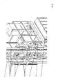
- the Fig. 1 to 5 show an elevator in the form of an external elevator, as it is often used for building renovation.
- the elevator comprises a guide 1 with a rectangular cross-section basic shape.
- the guide is formed by a total of four arranged in the corners of the rectangular cross section guide rails 2, which are connected to each other via a plurality of horizontally and diagonally extending struts.
- the cross section of the guide rails 2 is circular.
- the guide 1 also comprises a toothed rack 3 which extends parallel to the longitudinal axis of the guide 1.
- this rack 3 the drive pinion of a total of two traction drives 4, which are arranged on a roof structure of a car 5 of the elevator.
- the travel drives 4 of the car 5 are thus moved with the car 5, wherein the required for the operation of the travel drives 4 electrical energy is supplied via a entrained trailing cable 6.
- the roof structure of the car 5 is fixedly connected to a car cell 7, which is bounded by four outer walls and a bottom element and serves to accommodate the persons to be transported or the goods to be transported.
- the car 5 is guided on the guide 1 of the elevator, to which a plurality of inventively designed roller guides 8 are provided, the guide rollers 9 roll on the two, the car 5 facing guide rails 2 of the guide 1.
- the roller guides 8 are connected to the car 5 at several points.
- Each of the roller guides 8 comprises two spaced apart guide rollers 9, which are each rotatably arranged within a web.
- the web comprises two cover plates 10, in each of which a passage opening is provided at the end, which serve to receive the bearing shafts 11 of the guide rollers 9.
- the two cover plates 10 are each connected to each other via a transverse plate 12, to which also a fastening bolt 13 is attached, via which the respective roller guide 8 is connected to the car 5.
- connection of the fastening bolt 13 with the transverse plate 12 of the web of the respective roller guide 8 via a screw which simultaneously performs the function of a threaded spindle, based on the distance between the running surfaces of the guide rollers 9 to the respective guide rail 2 is adjustable.
- the details of this connection will be apparent from the cross section according to the Fig. 6 , There, it can be seen that the fastening bolt 13 is provided with a through-hole through which a threaded bolt 14 (a conventional screw with hexagonal head) protrudes.
- the threaded bolt 14 further protrudes through a through opening of the transverse plate 12 of the web and through a ball joint.
- the ball joint comprises a ball element 15 with a convex joint surface, which is slidably mounted in a concave joint receptacle 16.
- the joint receptacle 16 is connected to the transverse plate 12 of the web.
- the ball member 15 allows pivoting of the guide rollers 9 and the web comprehensive part of the roller guide 8 about an arbitrary axis, wherein the deflection is limited by the play of the threaded bolt 14 within the passage opening of the transverse plate 12.
- the ball element 15 is supported at the back, i. with the side facing away from the convex surface, on a plate spring assembly 27 and a washer 17 on a nut 18, which is screwed onto the threaded bolt 14.
- a protruding through a transverse opening of the threaded bolt 14 locking pin 19 prevents loosening of the nut 18 of the threaded bolt 14th
- the setting in the load during operation distance between the mounting bolt 13 and the guide rollers 9 and the web comprehensive part of the roller guide 8 can be changed. This serves to make the play surfaces of the guide rollers 9 rest without play on the guide rails 2 during assembly of the car.
- the plate spring assembly 27 ensures spring-loaded concerns of the guide rollers on the respective guide rail, which can be sure that the guide rollers during travel of the car 5 always have contact with the guide rail 2, whereby a good smoothness of the car 5 can be achieved.
- These roller guides can thus be used in particular where changing loads would lead to loss of contact between the guide rollers and the guide rail.
- the car is on the one hand in the roof construction (see. Fig. 3 ) as well as in the region of the lower end of the car cell (see. Fig. 4 ) each with a total of six roller guides 8 are provided, of which three in each case in the longitudinal direction (the guide) and in the circumferential direction (by 90 ° or 180 °) offset from each other on the corresponding guide rail 2.
- FIGS. 7 and 8 an alternative embodiment of a roller guide 8 according to the invention is shown, as in the elevator according to the Fig. 1 to 5 instead of the roller guides 8 shown there can be used.
- This roller guide 8 also comprises two guide rollers 9, which are interconnected via a web.
- the web comprises two cover plates 10 which are each provided at the end with a passage opening, which serve to receive bearing axles 11 of the guide rollers 9. Centered between the two guide rollers 9, the web is connected to a ball joint, which allows pivoting of the guide rollers 9 holding web.
- the ball joint comprises a tubular joint housing 20 which extends through through openings of the two cover plates 10 of the web and is connected thereto.
- a first hinge ring 21 is arranged, whose inner surface is concave. On this concave inner surface slides a convex outer surface of a second hinge ring 22 from.
- the second joint ring 22 is fixed on a joint body 23 and fixed via a hinge cover 24 which is connected via a screw connection 25 with the joint body 23.
- an eccentrically arranged threaded bore 26 is provided at the opposite end of the hinge body 24 of the joint body 23 .
- the eccentric threaded hole is therefore part of an eccentric rotary joint.
Abstract
Description
- Die Erfindung betrifft eine Rollenführung für ein an einer Führung geführtes Fahrelement, insbesondere ein Fahrkorb, eines Aufzugs, insbesondere eines Außenaufzugs, wie er beispielsweise als Bauaufzug zum Einsatz kommt.
- Außenaufzüge kommen beispielsweise auf Baustellen des Hochbaus zum Einsatz, um Personen und Material in die oberen Etagen des zu bauenden oder zu sanierenden Gebäudes zu transportieren.
- Solche Außenaufzüge weisen regelmäßig eine Führung auf, die an einer der Wände des Gebäudes befestigt ist und sich somit in senkrechter Richtung erstreckt. Die Führung besteht aus einem oder zwei Masttürmen, an dem/denen ein Fahrkorb verfahrbar befestigt ist. Der Fahrkorb dient der Aufnahme der zu befördernden Personen oder des zu befördernden Guts.
- Die Masttürme dienen somit der Führung der Bewegung des Fahrkorbs, wobei diese auch einen Teil des Antriebsstrangs darstellen können. In der Regel ist hierfür zumindest einer der Masttürme mit zumindest einer Zahnstange versehen, die sich in längsaxialer Richtung der Führung erstreckt und in die ein Ritzel eines elektrischen Fahrantriebs eingreift. Bei solchen Aufzügen ist der Fahrantrieb somit im Bereich des Fahrkorbs untergebracht und wird demnach mit diesem mitbewegt.
- Das Führen des Fahrkorbs an der Führung wird über mehrere Rollenführungen erreicht, die sich an einer Führungsschiene der Führung abstützen. Diese Führungsschiene ist in vielen Fällen mit einem kreisförmigen Querschnitt ausgebildet (sogenannte Rundführungen), wobei die einzelnen Führungsrollen der Rollenführungen mit einer hierzu korrespondierenden, konkaven Lauffläche versehen sind.
- Ein sich aus dieser Ausgestaltung der Rollenführungen und der Führungsschiene ergebendes Problem liegt darin, dass eine Relativbewegung der Führungsschienen zu den Führungsrollen in Querrichtung (der Führungsschienen) nicht möglich ist. Die Führungsschienen weisen jedoch regelmäßig einen nicht vollständig linearen Verlauf auf, was insbesondere darin begründet ist, dass die Führung an Ort und Stelle aus einer Vielzahl von relativ kurzen Führungsabschnitten zusammengesteckt wird und die Führungsabschnitte aus Kostengründen mit relativ großen Toleranzen gefertigt werden. Die Führungsrollen müssen somit einem nicht linearen Verlauf der Führungsschienen folgen, wobei dazu - in Abhängigkeit von der Position der jeweiligen Führungsrolle an der Führungsschiene - eine Bewegung der Führungsrolle in Richtung seiner Rotationsachse erforderlich sein kann. Um dies zu ermöglichen, kann vorgesehen sein, eine (Dreh-)Lagerung der Führungsrollen vorzusehen, die gleichzeitig eine axiale Verschiebbarkeit der Führungsrolle in der Halterung der Rollenführung zulässt. Eine solche Lagerung ist jedoch mit einem hohen konstruktiven Aufwand verbunden, wodurch in Folge die Kosten für den Aufzug erhöht werden.
- Um dieses Problem zu vermeiden besteht die Möglichkeit, die Führung des Fahrkorbs über sogenannte Parallelführungen zu realisieren, bei denen die Führungsschienen einen rechteckigen Querschnitt mit ebenen Führungsflächen aufweisen, auf denen Führungsrollen mit ebenen Laufflächen abrollen. Diese Konstellation ermöglicht eine Relativbewegung der Führungsrolle zu der Führungsschiene in dessen Querrichtung. Auf eine aufwändige (Dreh-)Lagerung der Führungsrollen mit einer längsaxialen Beweglichkeit kann dadurch verzichtet werden. Nachteilig ist jedoch, dass durch die gleitende Relativbewegung ein erhöhter Verschleiß an den Führungsrollen auftritt, dem dadurch begegnet wird, dass die Führungsrollen aus Metall ausgebildet werden. Metallische Führungsrolle, die auf einer metallischen Führungsschiene abrollen, zeichnen sich jedoch negativ durch einen vergleichseiwese geringen Fahrkomfort und insbesondere eine hohe Geräuschentwicklung aus.
- Ausgehend von diesem Stand der Technik lag der Erfindung die Aufgabe zugrunde, eine verbesserte Rollenführung für einen Aufzug anzugeben. Insbesondere sollte eine konstruktiv einfache Rollenführung angegeben werden, die sich für die Verwendung mit einer Rundführung eignet.
- Eine gattungsgemäße Rollenführung mit wenigstens einer Führungsrolle für ein an einer Führung eines Aufzugs geführtes Fahrelement, wie insbesondere einen Fahrkorb oder beispielsweise auch einen Kabelwagen, ist erfindungsgemäß dadurch gekennzeichnet, dass die Führungsrolle mit einem Gelenk verbunden ist, über das die Führungsrolle um zumindest eine Achse verschwenkbar ist.
- Durch die erfindungsgemäße Verschwenkbarkeit der Führungsrolle wird auf konstruktiv einfache Weise die Möglichkeit geschaffen, eine einfach gelagerte Führungsrolle so auszubilden, dass diese der Führung bei einem nichtlinearen Verlauf in Querrichtung folgt.
- Da die Führungsrolle(n) gattungsgemäßer Rollenführungen in der Regel derart an der Führung anliegen, dass die (mittige) Radialebene der Führungsrollen senkrecht bezüglich der Kontaktfläche der Führung angeordnet ist, ist in einer bevorzugten Ausführungsform der erfindungsgemäßen Rollenführung vorgesehen, dass die Führungsrolle(n) mittels des Gelenks um zumindest eine Achse verschwenkbar ist, die in oder parallel zu dieser Radialebene der Führungsrolle liegt.
- Vorzugsweise kann vorgesehen sein, dass das Gelenk als Kugelgelenk ausgebildet ist, womit auf konstruktiv einfache Weise ein Verschwenken um eine Vielzahl von Achsen ermöglicht wird.
- Weiterhin kann vorgesehen sein, dass die Führungsrolle(n) über einen Ausleger mit dem Gelenk verbunden sind. Diese Ausgestaltung weist den Vorteil auf, dass sich der Abstand des Drehpunkts von der/den Führungsrolle(n) vergrößert, so dass eine definierte seitliche Bewegung der Führungsrolle(n) mit einer nur relativ geringen Neigung verbunden ist.
- In einer bevorzugten Ausführungsform einer solchen erfindungsgemäßen Rollenführung ist vorgesehen, dass diese (mindestens) zwei Führungsrollen aufweist, die über einen Steg miteinander verbunden sind, wobei das Gelenk an einem ersten Ende des Auslegers angeordnet ist, der mit dem zweiten Ende in einem Bereich des Stegs zwischen den beiden Führungsrollen mit diesem verbunden ist.
- In einer alternativen Ausführungsform ist vorgesehen, dass die Rollenführung (mindestens) zwei Führungsrollen umfasst, die über einen Steg miteinander verbunden sind, wobei das Gelenk in einem Bereich des Stegs zwischen den beiden Führungsrollen mit diesem verbunden ist.
- Die Erfindung eignet sich insbesondere zur Verbesserung von Rollenführungen, deren Führungsrollen gekrümmte Laufbahnen aufweisen, die somit insbesondere mit sogenannten Rundführungen eines Aufzugs kombiniert werden. Hierbei sind die Laufbahnen insbesondere konkav ausgebildet, so dass diese mit herkömmlichen Rundführungen kombiniert werden können.
- Durch die erfindungsgemäß erreichte präzise Führung der Führungsrolle(n) an der Führung können ohne weiteres solche eingesetzt werden, bei denen zumindest die Laufbahnen aus Kunststoff ausgebildet sind. Dabei kann lediglich ein die Laufbahn ausbildender Teil der jeweiligen Führungsrolle oder die gesamte Führungsrolle aus Kunststoff ausgebildet ist.
- In einer weiterhin bevorzugten Ausführungsform der erfindungsgemäßen Rollenführung weist diese eine Verstelleinrichtung auf, mit der der Abstand zwischen einer Lauffläche der einzelnen Führungsrollen zu der Führung einstellbar ist. Diese Verstellbarkeit der Führungsrollen kann insbesondere in einer Richtung, die in oder parallel zu der (mittigen) Radialebene der Führungsrolle liegt, erfolgen. Damit wird die Möglichkeit geschaffen, die einzelnen Führungsrollen individuell einzustellen und möglichst exakt an der Führungsschiene anliegen zu lassen.
- Die Verstelleinrichtung kann vorzugsweise eine exzentrische Verdrehverbindung umfassen, die infolge einer exzentrischen Drehlagerung eine Relativdrehung von zwei Elementen in eine Translation dieser Elemente zueinander übersetzt.
- Auch kann die Verstelleinrichtung eine Gewindespindel aufweist, durch die auf konstruktiv einfache Weise eine Distanzeinstellung erreicht werden kann.
- Die Erfindung wird nachfolgend anhand von in den Zeichnungen dargestellten Ausführungsbeispielen näher erläutert.
- In den Zeichnungen zeigt:
- Fig. 1:
- in einer isometrischen Ansicht einen Aufzug mit erfindungsgemäßen Rollenführungen in einer ersten Ausführungsform;
- Fig. 2:
- den Aufzug gemäß
Fig. 1 in einer Rückansicht; - Fig. 3:
- einen ersten, vergrößerten Ausschnitt des Aufzugs gemäß den
Fig. 1 und2 ; - Fig. 4:
- einen zweiten, vergrößerten Ausschnitt des Aufzugs gemäß den
Fig. 1 und2 in einer isometrischen Ansicht; - Fig. 5:
- einen Querschnitt durch eine Rollenführung des Aufzugs gemäß den
Fig. 1 bis 4 ; - Fig. 6:
- eine Aufsicht auf einen Teil des Aufzugs gemäß den
Fig. 1 bis 4 ; - Fig. 7:
- einen Längsschnitt durch eine erfindungsgemäße Rollenführung in einer zweiten Ausführungsform; und
- Fig. 8:
- eine Seitenansicht der Rollenführung gemäß der
Fig. 7 . - Die
Fig. 1 bis 5 zeigen einen Aufzug in Form eines Außenaufzugs, wie er vielfach zur Gebäudesanierung eingesetzt wird. - Der Aufzug umfasst eine Führung 1 mit im Querschnitt rechteckiger Grundform. Die Führung wird durch insgesamt vier in den Ecken des rechteckigen Querschnitts angeordneten Führungsschienen 2 gebildet, die über eine Vielzahl von horizontal und diagonal verlaufenden Streben miteinander verbunden sind. Der Querschnitt der Führungsschienen 2 ist kreisförmig.
- Die Führung 1 umfasst zudem eine Zahnstange 3, die sich parallel zur Längsachse der Führung 1 erstreckt. In diese Zahnstange 3 greifen die Antriebsritzel von insgesamt zwei Fahrantrieben 4 ein, die auf einer Dachstruktur eines Fahrkorbs 5 des Aufzugs angeordnet sind. Die Fahrantriebe 4 des Fahrkorbs 5 werden somit mit dem Fahrkorb 5 mitbewegt, wobei die für den Betrieb der Fahrantriebe 4 erforderliche elektrische Energie über ein mitgeführtes Schleppkabel 6 zugeführt wird. Die Dachkonstruktion des Fahrkorbs 5 ist fest mit einer Fahrkorbzelle 7 verbunden, die über vier Außenwände und ein Bodenelement begrenzt ist und der Aufnahme der zu befördernden Personen oder des zu befördernden Guts dient.
- Der Fahrkorb 5 wird an der Führung 1 des Aufzugs geführt, wozu eine Vielzahl von erfindungsgemäß ausgebildeten Rollenführungen 8 vorgesehen sind, deren Führungsrollen 9 an den beiden, dem Fahrkorb 5 zugewandten Führungsschienen 2 der Führung 1 abrollen. Die Rollenführungen 8 sind an mehreren Stellen mit dem Fahrkorb 5 verbunden.
- Jede der Rollenführungen 8 umfasst zwei beabstandet voneinander angeordnete Führungsrollen 9, die jeweils drehbar innerhalb eines Stegs angeordnet sind. Der Steg umfasst jeweils zwei Deckplatten 10, in denen jeweils endseitig eine Durchgangsöffnung vorgesehen ist, die der Aufnahme der Lagerachsen 11 der Führungsrollen 9 dienen. Die beiden Deckplatten 10 sind jeweils über eine Querplatte 12 miteinander verbunden, an der zudem ein Befestigungsbolzen 13 befestigt ist, über den die jeweilige Rollenführung 8 mit dem Fahrkorb 5 verbunden ist.
- Die Verbindung des Befestigungsbolzens 13 mit der Querplatte 12 des Stegs der jeweiligen Rollenführung 8 erfolgt über eine Schraubverbindung, die gleichzeitig die Funktion einer Gewindespindel erfüllt, anhand der der Abstand der Laufflächen der Führungsrollen 9 zu der jeweiligen Führungsschiene 2 einstellbar ist. Die Details dieser Verbindung ergeben sich aus dem Querschnitt gemäß der
Fig. 6 . Dort ist zu erkennen, dass der Befestigungsbolzen 13 mit einer Durchgangsöffnung versehen ist, durch die ein Gewindebolzen 14 (einer herkömmlichen Schraube mit Sechskantkopf) hindurch ragt. Der Gewindebolzen 14 ragt weiter durch eine Durchgangsöffnung der Querplatte 12 des Stegs sowie durch ein Kugelgelenk. Durch das Kugelgelenk kann der die Führungsrollen 9 und den Steg umfassende Abschnitt der Rollenführung 8 verschwenkt werden, wie dies in derFig. 6 dargestellt ist. Dabei stellt sich ein Neigungswinkel zwischen der Längsachse des Gewindebolzens 14 und der/den (mittigen) Radialebene(n) der beiden Führungsrollen 9 ein. Dies dient primär dazu, einen Querversatz der Führungsrollen 9 zu der jeweiligen Führungsschiene 2, wie sie sich insbesondere aus einem nicht-linearen Verlauf der aus einzelnen Segmenten zusammengesetzten Führung lokal ergeben kann, zu kompensieren. - Das Kugelgelenk umfasst ein Kugelelement 15 mit einer konvexen Gelenkfläche, die in einer konkav ausgebildeten Gelenkaufnahme 16 gleitend gelagert. Die Gelenkaufnahme 16 ist mit der Querplatte 12 des Stegs verbunden. Das Kugelelement 15 ermöglicht ein Verschwenken des die Führungsrollen 9 und den Steg umfassenden Teils der Rollenführung 8 um eine beliebige Achse, wobei die Auslenkung durch das Spiel des Gewindebolzens 14 innerhalb der Durchgangsöffnung der Querplatte 12 begrenzt ist. Das Kugelelement 15 stützt sich rückseitig, d.h. mit der der konvexen Fläche abgewandten Seite, über ein Tellerfederpaket 27 und eine Unterlegscheiben 17 an einer Mutter 18 ab, die auf den Gewindebolzen 14 aufgeschraubt ist. Ein durch eine Queröffnung des Gewindebolzens 14 ragender Sicherungsstift 19 verhindert ein Lösen der Mutter 18 von dem Gewindebolzen 14.
- Durch ein Verschieben der Mutter 18 auf dem Gewindebolzen kann sich die bei der Belastung im Betrieb einstellende Distanz zwischen dem Befestigungsbolzen 13 und dem die Führungsrollen 9 und den Steg umfassenden Teil der Rollenführung 8 verändert werden. Dies dient dazu, bei der Montage des Fahrkorbs die Laufflächen der Führungsrollen 9 spielfrei an den Führungsschienen 2 anliegen zu lassen.
- Das Tellerfederpaket 27 sorgt für federbelastetes Anliegen der Führungsrollen an der jeweiligen Führungsschiene, wodurch sicher gestellt werden kann, dass die Führungsrollen während der Fahrt des Fahrkorbs 5 immer Kontakt zu der Führungsschiene 2 haben, wodurch eine gute Laufruhe des Fahrkorbs 5 erreicht werden kann. Diese Rollenführungen können somit insbesondere dort zum Einsatz kommen, wo wechselnde Belastungen zum Kontaktverlust zwischen den Führungsrollen und der Führungsschiene führen würden.
- Der Fahrkorb ist zum einen im Bereich der Dachkonstruktion (vgl.
Fig. 3 ) als auch im Bereich des unteren Endes der Fahrkorbzelle (vgl.Fig. 4 ) jeweils mit insgesamt sechs Rollenführungen 8 versehen, von denen jeweils drei sowohl in Längsrichtung (der Führung) als auch in Umfangsrichtung (um 90° bzw. 180°) versetzt zueinander an der entsprechenden Führungsschiene 2 anliegen. - In den
Fig. 7 und 8 ist eine alternative Ausführungsform einer erfindungsgemäßen Rollenführung 8 dargestellt, wie sie bei dem Aufzug gemäß denFig. 1 bis 5 anstelle der dort dargestellten Rollenführungen 8 zum Einsatz kommen kann. - Diese Rollenführung 8 umfasst ebenfalls zwei Führungsrollen 9, die über einen Steg miteinander verbunden sind. Der Steg umfasst zwei Deckplatten 10, die jeweils endseitig mit einer Durchgangsöffnung versehen sind, die der Aufnahme von Lagerachsen 11 der Führungsrollen 9 dienen. Mittig zwischen den zwei Führungsrollen 9 ist der Steg mit einem Kugelgelenk verbunden, das ein Verschwenken des die Führungsrollen 9 haltenden Stegs ermöglicht. Das Kugelgelenk umfasst ein rohrförmiges Gelenkgehäuse 20, das sich durch Durchgangsöffnungen der beiden Deckplatten 10 des Stegs hindurch erstreckt und mit diesen verbunden ist. In einem Abschnitt der Innenseite dieses Gelenkgehäuses 20 ist ein erster Gelenkring 21 angeordnet, dessen Innenfläche konkav ausgebildet ist. Auf dieser konkaven Innenfläche gleitet ein konvex ausgebildete Außenfläche eines zweiten Gelenkrings 22 ab. Der zweite Gelenkring 22 ist auf einem Gelenkkörper 23 fixiert und über einen Gelenkdeckel 24, der über eine Verschraubung 25 mit dem Gelenkkörper 23 verbunden ist, fixiert.
- An dem dem Gelenkdeckel 24 gegenüberliegenden Ende des Gelenkkörpers 23 ist eine exzentrisch angeordnete Gewindebohrung 26 vorgesehen. Diese Gewindebohrung 26 dient der Verschraubung der Rollenführung 8 mit dem Fahrkorb 5. Über die Exzentrizität der Gewindebohrung 26 besteht die Möglichkeit (über eine entsprechende rotatorische Ausrichtung des Gelenkkörpers und dem darauffolgenden Festziehen der Schraubverbindung), die Distanz der Führungsrollen 9 zu der jeweiligen Führungsschiene 2 einzustellen (und durch das Festziehen einer in die Gewindebohrung eingreifenden Schraube festzulegen) und somit sicherzustellen, dass jede der Führungsrollen 9 der Rollenführungen 8 möglichst spielfrei an der jeweiligen Führungsschiene anliegt. Die exzentrische Gewindebohrung ist demnach Teil einer exzentrischen Drehverbindung.
Claims (11)
- Rollenführung (8) für ein an einer Führung (1) geführtes Fahrelement eines Aufzugs mit wenigstens einer drehbar gelagerten Führungsrolle (9), dadurch gekennzeichnet, dass die Führungsrolle (9) mit einem Gelenk verbunden ist, über das die Führungsrolle (9) um zumindest eine Achse verschwenkbar ist.
- Rollenführung gemäß Anspruch 1, dadurch gekennzeichnet, dass die Führungsrolle (9) um eine Achse, die in oder parallel zu der Radialebene der Führungsrolle (9) verläuft, verschwenkbar ist.
- Rollenführung gemäß Anspruch 1 oder 2, dadurch gekennzeichnet, dass das Gelenk als Kugelgelenk ausgebildet ist.
- Rollenführung gemäß einem der vorhergehenden Ansprüche, dadurch gekennzeichnet, dass die Führungsrolle (9) über einen Ausleger mit dem Gelenk verbunden ist.
- Rollenführung gemäß Anspruch 4, dadurch gekennzeichnet, dass diese zwei Führungsrollen (9) umfasst, die über einen Steg miteinander verbunden sind, wobei das Gelenk an einem ersten Ende des Auslegers angeordnet ist, der mit dem zweiten Ende in einem Bereich zwischen den beiden Führungsrollen (9) mit dem Steg verbunden ist.
- Rollenführung gemäß einem der Ansprüche 1 bis 3, dadurch gekennzeichnet, dass diese zwei Führungsrollen (9) umfasst, die über einen Steg miteinander verbunden sind, wobei das Gelenk zwischen den beiden Führungsrollen (9) an dem Steg angeordnet ist.
- Rollenführung gemäß einem der vorhergehenden Ansprüche, dadurch gekennzeichnet, dass die Führungsrolle(n) (9) eine gekrümmte Laufbahn aufweisen.
- Rollenführung gemäß einem der vorhergehenden Ansprüche, dadurch gekennzeichnet, dass die Führungsrolle(n) (9) eine Laufbahnen aus Kunststoff aufweisen.
- Rollenführung gemäß einem der vorhergehenden Ansprüche, gekennzeichnet durch eine Verstelleinrichtung zur Einstellung des Abstands einer Lauffläche der Führungsrolle(n) (9) zu der Führung (1).
- Rollenführung nach Anspruch 9, dadurch gekennzeichnet, dass die Verstelleinrichtung eine exzentrische Verdrehverbindung umfasst.
- Rollenführung nach Anspruch 9, dadurch gekennzeichnet, dass die Verstelleinrichtung eine Gewindespindel aufweist.
Applications Claiming Priority (1)
| Application Number | Priority Date | Filing Date | Title |
|---|---|---|---|
| DE202011105039U DE202011105039U1 (de) | 2011-08-26 | 2011-08-26 | Rollenführung |
Publications (2)
| Publication Number | Publication Date |
|---|---|
| EP2562122A1 true EP2562122A1 (de) | 2013-02-27 |
| EP2562122B1 EP2562122B1 (de) | 2016-08-17 |
Family
ID=44900805
Family Applications (1)
| Application Number | Title | Priority Date | Filing Date |
|---|---|---|---|
| EP12004770.9A Active EP2562122B1 (de) | 2011-08-26 | 2012-06-26 | Rollenführung |
Country Status (4)
| Country | Link |
|---|---|
| US (1) | US20130048437A1 (de) |
| EP (1) | EP2562122B1 (de) |
| DE (1) | DE202011105039U1 (de) |
| RU (1) | RU2568002C2 (de) |
Families Citing this family (2)
| Publication number | Priority date | Publication date | Assignee | Title |
|---|---|---|---|---|
| NL2010181C2 (nl) * | 2013-01-25 | 2014-07-28 | Raxtar B V | Bouwliftsysteem. |
| CN108726315A (zh) * | 2018-08-03 | 2018-11-02 | 湖北江汉建筑工程机械有限公司 | 一种施工升降机导轨架下行机械安全保护装置 |
Citations (7)
| Publication number | Priority date | Publication date | Assignee | Title |
|---|---|---|---|---|
| US3856117A (en) * | 1973-09-25 | 1974-12-24 | Westinghouse Electric Corp | Elevator system |
| JPH033882A (ja) * | 1989-06-01 | 1991-01-09 | Hitachi Elevator Eng & Service Co Ltd | 昇降機用かごの昇降案内装置 |
| JPH04332513A (ja) * | 1991-05-08 | 1992-11-19 | Nippon Bisoo Kk | 外壁作業機のガイドローラ |
| WO1999043594A1 (en) * | 1998-02-26 | 1999-09-02 | Otto Ooms B.V. | A stair lift and a supporting unit for a stair lift |
| US6050370A (en) * | 1996-12-30 | 2000-04-18 | Lg Industrial Systems, Co., Ltd. | Guide roller apparatus for elevator system |
| JP2000159458A (ja) * | 1998-11-24 | 2000-06-13 | Hitachi Ltd | エレベータの案内装置 |
| CN2873721Y (zh) * | 2005-11-04 | 2007-02-28 | 陈百合 | 滚轮 |
Family Cites Families (20)
| Publication number | Priority date | Publication date | Assignee | Title |
|---|---|---|---|---|
| US2260922A (en) * | 1940-07-06 | 1941-10-28 | Elevator Safety Corp | Fluid controlled guide for elevator cars |
| DE1580860C3 (de) * | 1966-11-08 | 1980-04-17 | Pank Ag, Zuerich (Schweiz) | Hängebahnfahrwerk |
| SU522120A1 (ru) * | 1971-12-20 | 1976-07-25 | Предприятие П/Я А-3400 | Роликова направл юща шахтных подъемных сосудов |
| DE2329423C3 (de) * | 1973-02-09 | 1979-10-11 | Paul Dipl.-Ing. 8131 Aufkirchen Morsbach | Fahrzeug für eine Volksbelustigungsvorrichtung nach Art einer Achterbahn |
| AT338168B (de) * | 1974-01-25 | 1977-07-25 | Orenstein & Koppel Ag | Fordermittel, insbesondere rollsteig fur personentransport, mit einem in derselben forderebene uber umlenkstellen mittels zugmitteln gegenlaufig bewegten gliederband |
| SU613993A2 (ru) * | 1976-11-23 | 1978-07-05 | Государственный Макеевский Ордена Октябрьской Революции Научно-Исследовательский Институт По Безопасности Работ В Горной Промышленности | Направл юща роликоопора дл подъемных сосудов,движущихс по канатным проводникам |
| FR2373427A1 (fr) * | 1976-12-10 | 1978-07-07 | Monne Maxime | Perfectionnements apportes aux monorails et convoyeurs |
| CH644821A5 (de) * | 1979-12-11 | 1984-08-31 | Inventio Ag | Rollenfuehrungsschuh fuer aufzuege. |
| JPH0270847A (ja) * | 1988-09-07 | 1990-03-09 | Yoshida Kogyo Kk <Ykk> | 面材構成部材の取付け方法及びガイド治具 |
| FR2639077B1 (fr) * | 1988-11-17 | 1990-12-28 | Caoutchouc Manuf Plastique | Support elastique a rotules deformables pour la fixation d'un garnissage avec rappel elastique amorti presentant une course laterale importante |
| US5297658A (en) * | 1992-10-07 | 1994-03-29 | Otis Elevator Company | Roller cam adjuster for linear motors |
| FR2705636B1 (fr) * | 1993-05-26 | 1995-07-07 | Lohr Ind | Ensemble de guidage directionnel d'un véhicule routier le long d'un rail. |
| US5512791A (en) * | 1993-06-11 | 1996-04-30 | Lg Industrial Systems Co., Ltd. | Air gap adjusting apparatus for cylindrical linear motor of an elevator |
| NL1001327C2 (nl) * | 1995-10-02 | 1997-04-03 | Thyssen De Reus Bv | Loopwerk voor een aandrijfinrichting voor een railgeleide verplaatsingsinrichting. |
| EP0774439A1 (de) * | 1995-11-22 | 1997-05-21 | Inventio Ag | Führungseinrichtung |
| JPH09194163A (ja) * | 1996-01-19 | 1997-07-29 | Hitachi Ltd | エレベータ |
| JP4161063B2 (ja) * | 1999-10-22 | 2008-10-08 | 三菱電機株式会社 | エレベータ装置及びエレベータ装置のガイド装置 |
| US7455151B2 (en) * | 2003-04-07 | 2008-11-25 | Otis Elevator Company | Elevator roller guide |
| DE102004033754A1 (de) * | 2004-07-10 | 2006-02-09 | HIRO LIFT Hillenkötter + Ronsieck GmbH | Treppenschrägaufzug |
| JP5271905B2 (ja) * | 2007-07-19 | 2013-08-21 | 三菱重工業株式会社 | 軌道系交通システム |
-
2011
- 2011-08-26 DE DE202011105039U patent/DE202011105039U1/de not_active Expired - Lifetime
-
2012
- 2012-06-26 EP EP12004770.9A patent/EP2562122B1/de active Active
- 2012-08-13 US US13/572,969 patent/US20130048437A1/en not_active Abandoned
- 2012-08-24 RU RU2012136426/11A patent/RU2568002C2/ru active
Patent Citations (7)
| Publication number | Priority date | Publication date | Assignee | Title |
|---|---|---|---|---|
| US3856117A (en) * | 1973-09-25 | 1974-12-24 | Westinghouse Electric Corp | Elevator system |
| JPH033882A (ja) * | 1989-06-01 | 1991-01-09 | Hitachi Elevator Eng & Service Co Ltd | 昇降機用かごの昇降案内装置 |
| JPH04332513A (ja) * | 1991-05-08 | 1992-11-19 | Nippon Bisoo Kk | 外壁作業機のガイドローラ |
| US6050370A (en) * | 1996-12-30 | 2000-04-18 | Lg Industrial Systems, Co., Ltd. | Guide roller apparatus for elevator system |
| WO1999043594A1 (en) * | 1998-02-26 | 1999-09-02 | Otto Ooms B.V. | A stair lift and a supporting unit for a stair lift |
| JP2000159458A (ja) * | 1998-11-24 | 2000-06-13 | Hitachi Ltd | エレベータの案内装置 |
| CN2873721Y (zh) * | 2005-11-04 | 2007-02-28 | 陈百合 | 滚轮 |
Also Published As
| Publication number | Publication date |
|---|---|
| EP2562122B1 (de) | 2016-08-17 |
| RU2012136426A (ru) | 2014-02-27 |
| RU2568002C2 (ru) | 2015-11-10 |
| DE202011105039U1 (de) | 2011-10-05 |
| US20130048437A1 (en) | 2013-02-28 |
Similar Documents
| Publication | Publication Date | Title |
|---|---|---|
| WO2015039159A1 (de) | Schiebetürmodul/schwenkschiebetürmodul mit fliegender lagerung einer zahnstange eines zahnstangenantriebs | |
| AT519903B1 (de) | Schiene zur Führung eines Schlittens einer Möbeltüre | |
| AT507492B1 (de) | Aufhängung einer schiebetüre | |
| EP3207200A1 (de) | Laufwagen eines abstellbaren schiebeflügels | |
| EP2074050A1 (de) | Säulenhebebühne für kraftfahrzeuge | |
| EP2562122B1 (de) | Rollenführung | |
| EP0760415B1 (de) | Schiebetoranlage | |
| EP1108906B1 (de) | Linearführungseinheit | |
| WO2019155088A1 (de) | Autoparkvorrichtung | |
| DE4431286A1 (de) | Linearführung | |
| DE102007053465B4 (de) | Überdachung | |
| WO2011124453A1 (de) | Vorrichtung zur neigungsverstellung einer frontblende | |
| AT410819B (de) | Türbefestigung | |
| EP1852567B1 (de) | Laufwagen | |
| CH686690A5 (de) | Laufwerk sowie Verschiebeeinrichtung. | |
| DE19744149A1 (de) | Führungsanordnung für schiebbare Einrichtungen | |
| WO2011063535A1 (de) | Laufwerk für eine schiebetür | |
| DE102014220564B3 (de) | Rollenwagen | |
| EP0639134B1 (de) | Verriegelungsvorrichtung | |
| DE102016201816B4 (de) | Vorrichtung zum Verriegeln eines verfahrbaren Dachs | |
| EP1896229B1 (de) | Auflagetisch mit in der grösse variabler auflagefläche | |
| DE3525025A1 (de) | Fuehrung fuer eine befahreinrichtung eines bauwerkes | |
| EP4108877A1 (de) | Scharnier für eine türe, ein fenster oder ein ähnliches bauteil | |
| DE4406905A1 (de) | Seilbahn für Kinderspielplätze | |
| DE3729807C2 (de) |
Legal Events
| Date | Code | Title | Description |
|---|---|---|---|
| PUAI | Public reference made under article 153(3) epc to a published international application that has entered the european phase |
Free format text: ORIGINAL CODE: 0009012 |
|
| AK | Designated contracting states |
Kind code of ref document: A1 Designated state(s): AL AT BE BG CH CY CZ DE DK EE ES FI FR GB GR HR HU IE IS IT LI LT LU LV MC MK MT NL NO PL PT RO RS SE SI SK SM TR |
|
| AX | Request for extension of the european patent |
Extension state: BA ME |
|
| 17P | Request for examination filed |
Effective date: 20130826 |
|
| RBV | Designated contracting states (corrected) |
Designated state(s): AL AT BE BG CH CY CZ DE DK EE ES FI FR GB GR HR HU IE IS IT LI LT LU LV MC MK MT NL NO PL PT RO RS SE SI SK SM TR |
|
| 17Q | First examination report despatched |
Effective date: 20131010 |
|
| GRAP | Despatch of communication of intention to grant a patent |
Free format text: ORIGINAL CODE: EPIDOSNIGR1 |
|
| INTG | Intention to grant announced |
Effective date: 20160420 |
|
| GRAS | Grant fee paid |
Free format text: ORIGINAL CODE: EPIDOSNIGR3 |
|
| GRAA | (expected) grant |
Free format text: ORIGINAL CODE: 0009210 |
|
| AK | Designated contracting states |
Kind code of ref document: B1 Designated state(s): AL AT BE BG CH CY CZ DE DK EE ES FI FR GB GR HR HU IE IS IT LI LT LU LV MC MK MT NL NO PL PT RO RS SE SI SK SM TR |
|
| REG | Reference to a national code |
Ref country code: GB Ref legal event code: FG4D Free format text: NOT ENGLISH |
|
| REG | Reference to a national code |
Ref country code: CH Ref legal event code: EP |
|
| REG | Reference to a national code |
Ref country code: IE Ref legal event code: FG4D Free format text: LANGUAGE OF EP DOCUMENT: GERMAN |
|
| REG | Reference to a national code |
Ref country code: AT Ref legal event code: REF Ref document number: 820853 Country of ref document: AT Kind code of ref document: T Effective date: 20160915 |
|
| REG | Reference to a national code |
Ref country code: DE Ref legal event code: R096 Ref document number: 502012007944 Country of ref document: DE |
|
| REG | Reference to a national code |
Ref country code: NL Ref legal event code: MP Effective date: 20160817 |
|
| REG | Reference to a national code |
Ref country code: LT Ref legal event code: MG4D |
|
| PG25 | Lapsed in a contracting state [announced via postgrant information from national office to epo] |
Ref country code: LT Free format text: LAPSE BECAUSE OF FAILURE TO SUBMIT A TRANSLATION OF THE DESCRIPTION OR TO PAY THE FEE WITHIN THE PRESCRIBED TIME-LIMIT Effective date: 20160817 Ref country code: RS Free format text: LAPSE BECAUSE OF FAILURE TO SUBMIT A TRANSLATION OF THE DESCRIPTION OR TO PAY THE FEE WITHIN THE PRESCRIBED TIME-LIMIT Effective date: 20160817 Ref country code: FI Free format text: LAPSE BECAUSE OF FAILURE TO SUBMIT A TRANSLATION OF THE DESCRIPTION OR TO PAY THE FEE WITHIN THE PRESCRIBED TIME-LIMIT Effective date: 20160817 Ref country code: HR Free format text: LAPSE BECAUSE OF FAILURE TO SUBMIT A TRANSLATION OF THE DESCRIPTION OR TO PAY THE FEE WITHIN THE PRESCRIBED TIME-LIMIT Effective date: 20160817 Ref country code: NL Free format text: LAPSE BECAUSE OF FAILURE TO SUBMIT A TRANSLATION OF THE DESCRIPTION OR TO PAY THE FEE WITHIN THE PRESCRIBED TIME-LIMIT Effective date: 20160817 Ref country code: IT Free format text: LAPSE BECAUSE OF FAILURE TO SUBMIT A TRANSLATION OF THE DESCRIPTION OR TO PAY THE FEE WITHIN THE PRESCRIBED TIME-LIMIT Effective date: 20160817 Ref country code: NO Free format text: LAPSE BECAUSE OF FAILURE TO SUBMIT A TRANSLATION OF THE DESCRIPTION OR TO PAY THE FEE WITHIN THE PRESCRIBED TIME-LIMIT Effective date: 20161117 |
|
| PG25 | Lapsed in a contracting state [announced via postgrant information from national office to epo] |
Ref country code: GR Free format text: LAPSE BECAUSE OF FAILURE TO SUBMIT A TRANSLATION OF THE DESCRIPTION OR TO PAY THE FEE WITHIN THE PRESCRIBED TIME-LIMIT Effective date: 20161118 Ref country code: SE Free format text: LAPSE BECAUSE OF FAILURE TO SUBMIT A TRANSLATION OF THE DESCRIPTION OR TO PAY THE FEE WITHIN THE PRESCRIBED TIME-LIMIT Effective date: 20160817 Ref country code: PT Free format text: LAPSE BECAUSE OF FAILURE TO SUBMIT A TRANSLATION OF THE DESCRIPTION OR TO PAY THE FEE WITHIN THE PRESCRIBED TIME-LIMIT Effective date: 20161219 Ref country code: PL Free format text: LAPSE BECAUSE OF FAILURE TO SUBMIT A TRANSLATION OF THE DESCRIPTION OR TO PAY THE FEE WITHIN THE PRESCRIBED TIME-LIMIT Effective date: 20160817 Ref country code: LV Free format text: LAPSE BECAUSE OF FAILURE TO SUBMIT A TRANSLATION OF THE DESCRIPTION OR TO PAY THE FEE WITHIN THE PRESCRIBED TIME-LIMIT Effective date: 20160817 Ref country code: ES Free format text: LAPSE BECAUSE OF FAILURE TO SUBMIT A TRANSLATION OF THE DESCRIPTION OR TO PAY THE FEE WITHIN THE PRESCRIBED TIME-LIMIT Effective date: 20160817 |
|
| PG25 | Lapsed in a contracting state [announced via postgrant information from national office to epo] |
Ref country code: RO Free format text: LAPSE BECAUSE OF FAILURE TO SUBMIT A TRANSLATION OF THE DESCRIPTION OR TO PAY THE FEE WITHIN THE PRESCRIBED TIME-LIMIT Effective date: 20160817 Ref country code: EE Free format text: LAPSE BECAUSE OF FAILURE TO SUBMIT A TRANSLATION OF THE DESCRIPTION OR TO PAY THE FEE WITHIN THE PRESCRIBED TIME-LIMIT Effective date: 20160817 |
|
| REG | Reference to a national code |
Ref country code: DE Ref legal event code: R097 Ref document number: 502012007944 Country of ref document: DE |
|
| PG25 | Lapsed in a contracting state [announced via postgrant information from national office to epo] |
Ref country code: CZ Free format text: LAPSE BECAUSE OF FAILURE TO SUBMIT A TRANSLATION OF THE DESCRIPTION OR TO PAY THE FEE WITHIN THE PRESCRIBED TIME-LIMIT Effective date: 20160817 Ref country code: BG Free format text: LAPSE BECAUSE OF FAILURE TO SUBMIT A TRANSLATION OF THE DESCRIPTION OR TO PAY THE FEE WITHIN THE PRESCRIBED TIME-LIMIT Effective date: 20161117 Ref country code: SM Free format text: LAPSE BECAUSE OF FAILURE TO SUBMIT A TRANSLATION OF THE DESCRIPTION OR TO PAY THE FEE WITHIN THE PRESCRIBED TIME-LIMIT Effective date: 20160817 Ref country code: SK Free format text: LAPSE BECAUSE OF FAILURE TO SUBMIT A TRANSLATION OF THE DESCRIPTION OR TO PAY THE FEE WITHIN THE PRESCRIBED TIME-LIMIT Effective date: 20160817 Ref country code: DK Free format text: LAPSE BECAUSE OF FAILURE TO SUBMIT A TRANSLATION OF THE DESCRIPTION OR TO PAY THE FEE WITHIN THE PRESCRIBED TIME-LIMIT Effective date: 20160817 |
|
| PLBE | No opposition filed within time limit |
Free format text: ORIGINAL CODE: 0009261 |
|
| STAA | Information on the status of an ep patent application or granted ep patent |
Free format text: STATUS: NO OPPOSITION FILED WITHIN TIME LIMIT |
|
| REG | Reference to a national code |
Ref country code: FR Ref legal event code: PLFP Year of fee payment: 6 |
|
| 26N | No opposition filed |
Effective date: 20170518 |
|
| PG25 | Lapsed in a contracting state [announced via postgrant information from national office to epo] |
Ref country code: SI Free format text: LAPSE BECAUSE OF FAILURE TO SUBMIT A TRANSLATION OF THE DESCRIPTION OR TO PAY THE FEE WITHIN THE PRESCRIBED TIME-LIMIT Effective date: 20160817 |
|
| PG25 | Lapsed in a contracting state [announced via postgrant information from national office to epo] |
Ref country code: MC Free format text: LAPSE BECAUSE OF FAILURE TO SUBMIT A TRANSLATION OF THE DESCRIPTION OR TO PAY THE FEE WITHIN THE PRESCRIBED TIME-LIMIT Effective date: 20160817 |
|
| REG | Reference to a national code |
Ref country code: CH Ref legal event code: PL |
|
| REG | Reference to a national code |
Ref country code: IE Ref legal event code: MM4A |
|
| PG25 | Lapsed in a contracting state [announced via postgrant information from national office to epo] |
Ref country code: LI Free format text: LAPSE BECAUSE OF NON-PAYMENT OF DUE FEES Effective date: 20170630 Ref country code: CH Free format text: LAPSE BECAUSE OF NON-PAYMENT OF DUE FEES Effective date: 20170630 Ref country code: LU Free format text: LAPSE BECAUSE OF NON-PAYMENT OF DUE FEES Effective date: 20170626 Ref country code: IE Free format text: LAPSE BECAUSE OF NON-PAYMENT OF DUE FEES Effective date: 20170626 |
|
| REG | Reference to a national code |
Ref country code: BE Ref legal event code: MM Effective date: 20170630 |
|
| REG | Reference to a national code |
Ref country code: FR Ref legal event code: PLFP Year of fee payment: 7 |
|
| REG | Reference to a national code |
Ref country code: AT Ref legal event code: MM01 Ref document number: 820853 Country of ref document: AT Kind code of ref document: T Effective date: 20170626 |
|
| PG25 | Lapsed in a contracting state [announced via postgrant information from national office to epo] |
Ref country code: BE Free format text: LAPSE BECAUSE OF NON-PAYMENT OF DUE FEES Effective date: 20170630 |
|
| PG25 | Lapsed in a contracting state [announced via postgrant information from national office to epo] |
Ref country code: MT Free format text: LAPSE BECAUSE OF FAILURE TO SUBMIT A TRANSLATION OF THE DESCRIPTION OR TO PAY THE FEE WITHIN THE PRESCRIBED TIME-LIMIT Effective date: 20160817 |
|
| PG25 | Lapsed in a contracting state [announced via postgrant information from national office to epo] |
Ref country code: AL Free format text: LAPSE BECAUSE OF FAILURE TO SUBMIT A TRANSLATION OF THE DESCRIPTION OR TO PAY THE FEE WITHIN THE PRESCRIBED TIME-LIMIT Effective date: 20160817 |
|
| PG25 | Lapsed in a contracting state [announced via postgrant information from national office to epo] |
Ref country code: AT Free format text: LAPSE BECAUSE OF NON-PAYMENT OF DUE FEES Effective date: 20170626 |
|
| PG25 | Lapsed in a contracting state [announced via postgrant information from national office to epo] |
Ref country code: HU Free format text: LAPSE BECAUSE OF FAILURE TO SUBMIT A TRANSLATION OF THE DESCRIPTION OR TO PAY THE FEE WITHIN THE PRESCRIBED TIME-LIMIT; INVALID AB INITIO Effective date: 20120626 |
|
| PG25 | Lapsed in a contracting state [announced via postgrant information from national office to epo] |
Ref country code: CY Free format text: LAPSE BECAUSE OF NON-PAYMENT OF DUE FEES Effective date: 20160817 |
|
| PG25 | Lapsed in a contracting state [announced via postgrant information from national office to epo] |
Ref country code: MK Free format text: LAPSE BECAUSE OF FAILURE TO SUBMIT A TRANSLATION OF THE DESCRIPTION OR TO PAY THE FEE WITHIN THE PRESCRIBED TIME-LIMIT Effective date: 20160817 |
|
| PG25 | Lapsed in a contracting state [announced via postgrant information from national office to epo] |
Ref country code: TR Free format text: LAPSE BECAUSE OF FAILURE TO SUBMIT A TRANSLATION OF THE DESCRIPTION OR TO PAY THE FEE WITHIN THE PRESCRIBED TIME-LIMIT Effective date: 20160817 |
|
| PG25 | Lapsed in a contracting state [announced via postgrant information from national office to epo] |
Ref country code: IS Free format text: LAPSE BECAUSE OF FAILURE TO SUBMIT A TRANSLATION OF THE DESCRIPTION OR TO PAY THE FEE WITHIN THE PRESCRIBED TIME-LIMIT Effective date: 20161217 |
|
| REG | Reference to a national code |
Ref country code: DE Ref legal event code: R082 Ref document number: 502012007944 Country of ref document: DE Representative=s name: ZEITLER VOLPERT KANDLBINDER PATENT- UND RECHTS, DE Ref country code: DE Ref legal event code: R081 Ref document number: 502012007944 Country of ref document: DE Owner name: GEDA GMBH, DE Free format text: FORMER OWNER: GEDA-DECHENTREITER GMBH & CO. KG, 86663 ASBACH-BAEUMENHEIM, DE Ref country code: DE Ref legal event code: R082 Ref document number: 502012007944 Country of ref document: DE Representative=s name: ZEITLER VOLPERT KANDLBINDER PATENTANWAELTE PAR, DE |
|
| PGFP | Annual fee paid to national office [announced via postgrant information from national office to epo] |
Ref country code: FR Payment date: 20230621 Year of fee payment: 12 |
|
| PGFP | Annual fee paid to national office [announced via postgrant information from national office to epo] |
Ref country code: GB Payment date: 20230622 Year of fee payment: 12 |
|
| REG | Reference to a national code |
Ref country code: DE Ref legal event code: R082 Ref document number: 502012007944 Country of ref document: DE Representative=s name: KANDLBINDER, MARKUS, DIPL.-PHYS., DE |
|
| PGFP | Annual fee paid to national office [announced via postgrant information from national office to epo] |
Ref country code: DE Payment date: 20230828 Year of fee payment: 12 |