EP2561816B1 - Outil pour un instrument chirurgical micro-invasif - Google Patents
Outil pour un instrument chirurgical micro-invasif Download PDFInfo
- Publication number
- EP2561816B1 EP2561816B1 EP12176339.5A EP12176339A EP2561816B1 EP 2561816 B1 EP2561816 B1 EP 2561816B1 EP 12176339 A EP12176339 A EP 12176339A EP 2561816 B1 EP2561816 B1 EP 2561816B1
- Authority
- EP
- European Patent Office
- Prior art keywords
- shaft
- tool
- distal end
- coupling
- end portion
- Prior art date
- Legal status (The legal status is an assumption and is not a legal conclusion. Google has not performed a legal analysis and makes no representation as to the accuracy of the status listed.)
- Active
Links
- 230000008878 coupling Effects 0.000 claims description 102
- 238000010168 coupling process Methods 0.000 claims description 102
- 238000005859 coupling reaction Methods 0.000 claims description 102
- 230000005540 biological transmission Effects 0.000 claims description 51
- 230000002093 peripheral effect Effects 0.000 description 10
- 239000000463 material Substances 0.000 description 6
- 239000002184 metal Substances 0.000 description 6
- 210000002105 tongue Anatomy 0.000 description 5
- 230000008901 benefit Effects 0.000 description 3
- 238000004140 cleaning Methods 0.000 description 2
- 238000011161 development Methods 0.000 description 2
- 230000018109 developmental process Effects 0.000 description 2
- 238000006073 displacement reaction Methods 0.000 description 2
- 239000012777 electrically insulating material Substances 0.000 description 2
- 235000003332 Ilex aquifolium Nutrition 0.000 description 1
- 241000209027 Ilex aquifolium Species 0.000 description 1
- 238000005452 bending Methods 0.000 description 1
- 238000001574 biopsy Methods 0.000 description 1
- 230000008859 change Effects 0.000 description 1
- 239000000356 contaminant Substances 0.000 description 1
- 230000001419 dependent effect Effects 0.000 description 1
- 230000001066 destructive effect Effects 0.000 description 1
- 230000004069 differentiation Effects 0.000 description 1
- 230000005684 electric field Effects 0.000 description 1
- 238000010292 electrical insulation Methods 0.000 description 1
- 230000006872 improvement Effects 0.000 description 1
- 238000012977 invasive surgical procedure Methods 0.000 description 1
- 238000002357 laparoscopic surgery Methods 0.000 description 1
- 238000005498 polishing Methods 0.000 description 1
- 238000003825 pressing Methods 0.000 description 1
- 230000001954 sterilising effect Effects 0.000 description 1
- 238000004659 sterilization and disinfection Methods 0.000 description 1
- 238000001356 surgical procedure Methods 0.000 description 1
- 230000001360 synchronised effect Effects 0.000 description 1
- 230000007704 transition Effects 0.000 description 1
Images


Classifications
-
- A—HUMAN NECESSITIES
- A61—MEDICAL OR VETERINARY SCIENCE; HYGIENE
- A61B—DIAGNOSIS; SURGERY; IDENTIFICATION
- A61B17/00—Surgical instruments, devices or methods, e.g. tourniquets
- A61B17/28—Surgical forceps
- A61B17/29—Forceps for use in minimally invasive surgery
-
- A—HUMAN NECESSITIES
- A61—MEDICAL OR VETERINARY SCIENCE; HYGIENE
- A61B—DIAGNOSIS; SURGERY; IDENTIFICATION
- A61B17/00—Surgical instruments, devices or methods, e.g. tourniquets
- A61B2017/0046—Surgical instruments, devices or methods, e.g. tourniquets with a releasable handle; with handle and operating part separable
- A61B2017/00464—Surgical instruments, devices or methods, e.g. tourniquets with a releasable handle; with handle and operating part separable for use with different instruments
-
- A—HUMAN NECESSITIES
- A61—MEDICAL OR VETERINARY SCIENCE; HYGIENE
- A61B—DIAGNOSIS; SURGERY; IDENTIFICATION
- A61B17/00—Surgical instruments, devices or methods, e.g. tourniquets
- A61B17/28—Surgical forceps
- A61B17/29—Forceps for use in minimally invasive surgery
- A61B2017/2901—Details of shaft
- A61B2017/2904—Details of shaft curved, but rigid
-
- A—HUMAN NECESSITIES
- A61—MEDICAL OR VETERINARY SCIENCE; HYGIENE
- A61B—DIAGNOSIS; SURGERY; IDENTIFICATION
- A61B17/00—Surgical instruments, devices or methods, e.g. tourniquets
- A61B17/28—Surgical forceps
- A61B17/29—Forceps for use in minimally invasive surgery
- A61B2017/2926—Details of heads or jaws
- A61B2017/2927—Details of heads or jaws the angular position of the head being adjustable with respect to the shaft
- A61B2017/2929—Details of heads or jaws the angular position of the head being adjustable with respect to the shaft with a head rotatable about the longitudinal axis of the shaft
-
- A—HUMAN NECESSITIES
- A61—MEDICAL OR VETERINARY SCIENCE; HYGIENE
- A61B—DIAGNOSIS; SURGERY; IDENTIFICATION
- A61B17/00—Surgical instruments, devices or methods, e.g. tourniquets
- A61B17/28—Surgical forceps
- A61B17/29—Forceps for use in minimally invasive surgery
- A61B2017/2926—Details of heads or jaws
- A61B2017/2931—Details of heads or jaws with releasable head
Definitions
- the present invention relates to a shank for a micro-invasive surgical instrument, a micro-invasive surgical instrument and in particular to the ability of a tool to rotate at the distal end section of the shank.
- microinvasive surgical instruments include a long and thin shank, a tool at the distal end portion of the shank, and a manipulation device at the proximal end portion of the shank.
- the tool comprises, for example, grasping, dissecting, biopsy or other forceps, scissors or a needle holder with at least two straight or curved jaws, blades or other jaw parts, at least one of which is movable.
- the tool comprises another active device, for example a manipulator with a finger or a finger-shaped device or an electrode in the form of a hook or another shape.
- the shaft contains (at least) one transmission rod, which is usually arranged in a closed channel inside the shaft.
- the handling device comprises one or more actuating devices that can be moved relative to one another, for example two handle parts, which medical staff can move relative to one another with one hand.
- the proximal end portion and the distal end portion of the transmission rod are coupled to the actuating device or to the tool in such a way that a force exerted by medical personnel on the actuating devices or a relative movement of the actuating devices caused by medical personnel is transmitted to the tool, for example in order to move jaws towards one another or to press them together.
- the tool and part of the shaft are inserted, for example, through a natural or artificial body opening into a natural or artificial cavity in a patient's body.
- the development of micro-invasive surgical techniques is moving towards using ever smaller and, above all, fewer and fewer accesses.
- instruments with curved shafts can be used.
- an instrument with a curved shank cannot easily be rotated about its longitudinal axis within the access in order to change the orientation of the tool at its distal end section.
- a jaw part is detachably connected to a shaft by means of a bayonet lock. In the connected state, the jaw part can be rotated relative to the shank.
- the shaft is detachably connected to a handle.
- the curved shaft can be rotated in relation to the handle by means of a hand wheel which is connected in a torque-proof manner to an outer shaft tube.
- An inner tube is connected to another handwheel on the handle.
- the instrument can be designed as a unipolar or bipolar HF instrument.
- a surgical instrument with a jaw unit, a shaft and a handle unit.
- the jaw unit is detachably attached to the end of a shank tube of the shank and can be rotated relative to it.
- the tool, shaft and handling device of a micro-invasive surgical instrument should be able to be separated from one another and connected or coupled to one another without the use of aids in order to enable the instrument to be cleaned easily and thoroughly.
- the tool and the distal end section of the shank in such a way that the tool can be assembled and disassembled on the shank in an over-open assembly position.
- some aspects of both the coupling of the tool to the shank and the coupling of the shank to the handling device have not yet been completely satisfactorily solved.
- the WO1998034543A1 shows a shank for a micro-invasive surgical instrument with a shank tube, wherein the shank can be mechanically releasably coupled to a tool and the coupling device can be mechanically connected to the distal end section of the shank tube.
- a shank for a micro-invasive surgical instrument which shows a shank tube with a proximal and distal end section, wherein the shank can be mechanically detachably coupled to a tool and additionally has a groove and the device for coupling to the distal end section of the shank tube mechanically connectable and a rotation of the coupling device relative to the shank tube about the circumferential axis of the distal end section of the shank is made possible.
- Embodiments of the present invention are based on the idea of implementing the rotatability of a tool of a micro-invasive surgical instrument on the distal end section of the shaft instead of on the tool.
- this can enable a number of advantages.
- some of the mechanical complexity can be shifted from the tool to the shank.
- the tool can be produced more cost-effectively.
- a further advantage can consist in the fact that a rotation bearing is simpler in the distal end section of a shaft, which in many cases is mechanically less complex can be integrated than in an often mechanically much more complex tool.
- a further advantage can be that the coupling between the tool and the shaft can move closer to the distal end of the tool, as a result of which the torques to be absorbed by the coupling when the tool is used as intended can be reduced.
- a shaft for a microinvasive surgical instrument comprises a shaft tube with a proximal end section and a distal end section, a coupling device for releasably mechanically coupling the shaft to a tool, and a rotary bearing that mechanically connects the coupling device to the distal end section of the shaft tube, the rotary bearing is designed to allow rotation of the coupling device relative to the shaft tube about the longitudinal axis of the distal end portion of the shaft.
- the shaft tube can be mechanically connectable or connected directly or indirectly to a handling device.
- An indirect connection of the shaft tube to a handling device includes, for example, a coupling device that is joined to the shaft tube and has one or more grooves or webs for mechanical locking with the handling device.
- the shaft tube can be permanently and not non-destructively separable from the handling device without the use of tools.
- the shaft tube can be mechanically connectable or connected to a handling device in such a way that it can be rotated about its longitudinal axis at the proximal end section relative to the handling device.
- the shaft tube has a central channel for accommodating a rigid or flexible transmission rod, with the central channel extending over the entire length from the proximal end to the distal end of the shaft tube.
- Both the shaft tube and the channel each have, in particular, a circular cross section or a cross section with a circular edge.
- the coupling device is designed, in particular, to enable both mechanical coupling and releasing of the mechanical coupling without the use of tools and to enable non-destructive. This makes it easier for medical and other personnel to handle the entire microinvasive surgical instrument before and after use and during cleaning and sterilization.
- the mechanical connection created by the rotary bearing between the coupling device and the distal end section of the shank tube cannot in particular be released non-destructively without a tool.
- the rotation bearing is designed in particular to exclusively allow rotation of the coupling device relative to the shaft tube around the longitudinal axis of the shaft—in the case of a curved shaft, around the longitudinal axis of the distal end section of the shaft or around the longitudinal axis of the shaft at its distal end section.
- the rotation bearing is designed in such a way that it prevents all three translational degrees of freedom and two of three rotational degrees of freedom—apart from mechanical play.
- the rotary bearing is designed in particular as a radial bearing.
- a radial bearing is a combination of a radial bearing that restricts the two translational degrees of freedom perpendicular to the longitudinal axis and the rotational degrees of freedom about both directions perpendicular to the longitudinal axis, and an axial bearing that restricts the translational degrees of freedom parallel to the longitudinal axis.
- the rotary bearing limits the movement of the coupling device relative to the shaft tube to a single rotational degree of freedom.
- the rotary bearing can comprise a radially inwardly projecting collar and a radially outwardly projecting collar, with either the radially outwardly projecting collar being rigidly connected to the coupling device and the radially inwardly projecting collar being connected to the distal end portion of the shaft tube are rigidly connected or vice versa.
- the two collars are in particular each arranged in the shape of a circular ring and symmetrically to the longitudinal axis of the shaft at its distal end section.
- the one radially inside The projecting collar engages in a radially outwardly opening groove with a corresponding cross-section, one flank of which is formed by the radially outwardly projecting collar.
- the radially outwardly projecting collar engages in a radially inwardly opening groove with a corresponding cross-section, one flank of which is formed by the radially inwardly projecting collar.
- the collars engage behind each other in such a way that the two collars can rotate relative to one another with little play and low friction, and thus also the coupling device and the distal end of the shaft tube relative to one another.
- the collars can each have a smaller extension in the radial direction than in the axial direction.
- the exemplary embodiments illustrated with reference to the attached figures show that two collars engaging behind one another in the axial direction can form a robust, low-backlash and low-friction rotary bearing.
- a shank as described here is curved in particular.
- the shank may be curved in a plane, with the centers of all cross-sections of the shank lying on a plane curve or a curve in a plane.
- the shank may be three-dimensionally curved, with the centers of all cross-sections of the shank lying on a curve that is not flat.
- the longitudinal axis of the shank or of another object means here in particular the axis to which the object in question is rotationally symmetrical or essentially rotationally symmetrical.
- these statements relate in particular to their ends, which in particular are straight or not curved, at least in sections.
- a shank as described here is designed in particular to be coupled to a tool which is provided for coupling to a shank without a rotary bearing.
- the shank is therefore intended and designed in particular for a combination or use with a conventional tool that is designed for conventional use is provided without a rotatability.
- the shank thus enables the ability to rotate, which, as described at the outset, is important for some applications, even when used with conventional tools that are already available in a clinic or other medical facility, for example.
- the shaft can thus enable a significant improvement in the functionality of micro-invasive surgical instruments with comparatively little effort.
- the coupling device of the shank is designed for coupling to a conventional tool.
- the coupling device is designed in particular for the ability to lock a mechanical coupling with a tool.
- the coupling device has in particular an axial groove or an axial slot, in which a locking device connected to a tool can engage in order to lock a coupling of the tool to the coupling device of the shank.
- the coupling device has in particular a groove or slot with an axial section and a peripheral section for receiving a lug on a tool.
- An axial section is a section extending in the axial direction or substantially in the axial direction.
- a peripheral portion is a portion extending in the circumferential direction or substantially in the circumferential direction.
- the axial section and the peripheral section are in particular arranged in an L-shape, so that the proximal end of the axial section merges into an end of the peripheral section or is identical to it.
- a cleat can be inserted into such a groove or such a slot by means of an axial and subsequent rotational movement of the tool relative to the coupling device.
- the coupling device can have two or more grooves or slots, which are spaced apart from one another in particular by equal angles, in order to simplify coupling of the tool and coupling device and to improve the mechanical robustness of the coupling.
- a shank as described herein may further include a sleeve member having a distal portion forming the coupling means and a proximal portion forming part of the rotary bearing.
- the sleeve member may include multiple coaxial sleeves for ease of manufacturability.
- the inner sleeve has a groove or slot as described above and is mated to an outer coaxial sleeve.
- a micro-invasive surgical instrument comprises a shank, as is described here, and a tool that can be detachably mechanically coupled to the coupling device at the distal end of the shank.
- a micro-invasive surgical instrument as described here can also include a handling device that can be coupled or is coupled to the proximal end of the shaft, the handling device having an actuating device for rotating a transmission rod arranged in the shaft whose distal end section is coupled to the tool is, has.
- the actuating device is designed in particular for manual or motorized turning of a proximal end section or a proximal region of the transmission rod.
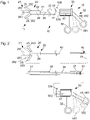
- figure 1 shows a schematic representation of a micro-invasive surgical instrument 10 with a distal end portion 11 and a proximal end portion 12.
- the micro-invasive surgical instrument 10 includes a tool 20, a shaft 30 and a handling device 50.
- the tool 20 has a first movable jaw part 25 and a second movable jaw part 26.
- the jaw parts 25, 26 are in figure 1 shown in solid lines in open positions 252,262 and in broken lines in closed positions 251,261.
- the jaw parts 25, 26 can each be straight or substantially straight or in the direction perpendicular to the character level of figure 1 and/or - deviating from the representation in figure 1 - in the drawing plane of figure 1 be curved.
- the proximal end portion 22 of the tool 20 is releasably mechanically coupled to a distal end portion 31 of the shank 30.
- the shank 30 is in figure 1 greatly abbreviated and shown straight for the sake of simplicity. Deviating from the representation in figure 1 the shank 30 can be flat or three-dimensionally curved. With a shape of the shaft 30 within a plane or - even more advantageous for some applications - spatially curved shape, the micro-invasive surgical instrument 10 can be particularly suitable for micro-invasive surgical procedures in which an endoscope and one or more instruments can be used simultaneously through a single access in be inserted into a body cavity.
- the proximal end section 32 of the shaft 30 is detachably mechanically coupled to the distal end section 51 of the handling device 50 .
- the handling device 50 has a rotary wheel 57 , a first handle part 58 and a second handle part 59 for handling the micro-invasive surgical instrument 10 .
- the rotary wheel 57 is provided for controlling a rotation of the tool 20, in particular the jaw parts 25, 26, about a longitudinal axis 29.
- the rotary wheel 57 can be rotated about an axis 578 which is also the longitudinal axis of the shaft 30 at its proximal end section 32 .
- axis 578 may be parallel to the longitudinal axis of shaft 30 at its proximal end portion 32.
- the rotary wheel 57 has a surface structure that enables reliable operation or actuation even when wearing gloves, for example the indicated webs in the axial direction.
- the handle parts 58, 59 are in particular - deviating from the figure 1 shown highly stylized shape - so arranged and shaped that medical personnel can grip both handle parts 58, 59 with one hand and move them relative to one another with little effort.
- At least one of the two handle parts 58, 59 can be moved relative to the other components of the handling device 50.
- the first handle part 58 is rigid and the second handle part 59 is arranged to be movable.
- the second handle part 59 is in particular between a first, in figure 1 Working position 591 shown in dashed line and a second, in figure 1 shown in solid line Working position 592 movable.
- the second handle part 59 of the handling device 50 is mechanically coupled to the jaw parts 25, 26 of the tool 20 in such a way that the jaw parts 25, 26 are in their closed positions 251, 261 when the second handle part 59 assumes its first working position 591, and that the jaw parts 25, 26 are in their open positions 252, 262 when the second handle part 59 assumes its second working position 592.
- figure 2 shows a schematic representation of parts or components of the above with reference to figure 1 illustrated micro-invasive surgical instrument 10, which can be mounted or assembled into an instrument without the use of tools.
- the micro-invasive surgical instrument 10 can be inserted into the in figure 2 parts or components shown separately can be disassembled. through the the entire figure 2
- the continuous dash-dotted line 19 indicates how these parts or components are to be put together.
- the tool 20 is in particular permanently connected to a transmission rod 40 which is provided for transmitting a force and a torque from the handling device 50 to the tool 20 .
- the inside figure 2 The non-illustrated distal end section of the transmission rod 40 is coupled to the jaw parts 25, 26 in such a way that a movement of the transmission rod 40 parallel to the longitudinal axis 29 of the tool 20 causes a synchronous movement of the jaw parts 25, 26.
- FIG. 25 At the proximal end portion 22 of the tool 20 and at the distal end portion 31 of the shaft 30 are in figure 2 bayonet coupling devices, not shown, and a locking device coupled to the transmission rod 40 are provided.
- the jaw parts 25, 26 are in figure 2 in solid lines in overopen positions 253, 263 and in dashed lines in the already above based on the figure 1 closed and open positions 251, 252, 261, 262 described.
- the jaws 25, 26 are in the over-open positions 253, 263, the coupled to the jaws 25, 26 and the distal end portion of the transmission rod 40 and in figure 2 not shown locking device inactive.
- the locking device coupled to the distal end section of the transmission rod 40 and indirectly to the jaw parts 25, 26 is in a work position or in a position within a work area.
- the proximal end portion 22 of the tool 20 and the distal end portion 31 of the shank 30 may have other coupling means.
- a locking device can be provided on the tool 20, which locks the mechanical connection between the tool 20 and the shaft 30 when the jaw parts 25, 26 are in the over-open positions 253, 263.
- the proximal end portion 32 of the shank 30 can be connected to the opposite end of the proximal end of the Shaft 30 protruding proximal end section 42 of the transmission rod 40 in the handling device 50 be used.
- the handling device 50 has an in figure 2 recess 503 indicated by a dotted line.
- the second handle part 59 is first inserted into an in figure 2 brought coupling position 593 shown in solid line.
- the second handle part 59 is in the coupling position 593, there is an in figure 2 rod coupling, not shown, inside the handling device 50 in a coupled position in which it can receive or release the proximal end section 42 of the transmission rod 40 .
- the figure 2 rod coupling not shown, inside the handling device 50 mechanically connected or coupled to the proximal end section 42 of the transmission rod 40 .
- the second handle part 59 moves into the first working position 591, the second working position 592 or a position between the first working position 591 and the second working position 592 above.
- the shaft 30 may have another rotary wheel near its proximal end, which is located near the distal end of the handler 50 when the proximal end portion 32 of the shaft 30 is inserted into the handler 50.
- the shaft 30 can be rotated about the longitudinal axis of the proximal end section 20 of the shaft 30 by means of a rotary wheel (not shown). This is particularly important when the shaft 30 deviates from the representations in the Figures 1 and 2 is curved. In this case, the curved shaft 30 and the tool 20 at the distal end of the curved shaft 30 can be rotated independently.
- the tool 20 can have another active device, in particular a manipulator, for example a finger-shaped manipulator, or an electrode, for example a hook-shaped electrode.
- a manipulator for example a finger-shaped manipulator
- an electrode for example a hook-shaped electrode
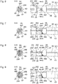
- the Figures 3 to 5 show schematic sectional views of an embodiment of the above with reference to FIG Figures 1 and 2 illustrated tool 20 and the distal end portion of the above based on the Figures 1 and 2 shown shank 30.
- the cutting planes of Figures 3 to 5 are parallel to the drawing planes of the Figures 1 and 2 and contain those in the Figures 1 and 2 indicated longitudinal axis 29 of the tool 20.
- the longitudinal axis 29 of the tool 20 is indicated by a dot-dash line.
- the longitudinal axis 29 of the tool 20 is the axis of symmetry of some, but by no means all, features of the tool 20.
- the longitudinal axis 29 of the tool coincides with the longitudinal axis of the shank 30 or - if the shank 30 is curved - with the longitudinal axis of the shank whose in the Figures 3 to 5 illustrated distal end portion 31 together.
- the jaw parts 25, 26 are shown in their over-open positions 253, 263, in which the mechanical connection between the tool 20 and the shaft 30 is unlocked, ie it can be established or released.
- the jaw parts 25, 26 are shown in their open positions 252, 262, the connection between tool 20 and shank 30 is locked.
- the jaw parts 25, 26 are shown in their closed positions 251, 261, the connection between tool 20 and shank 30 is also locked.
- the transmission rod 40 has two joints 415, 416 on the distal end section 41.
- a first connecting rod 256 connects the first joint 415 on the distal end portion 41 of the transmission rod 40 with a shaft 232 spaced joint 258 on the first jaw part 25.
- a second connecting rod 266 connects the second joint 416 on the distal end portion 41 of the transmission rod 40 with one of the Shaft 232 spaced joint 268 on the second jaw part 26.
- the tool 20 has a joint device 23 which is designed in a distal area in the form of a fork with two bars.
- a spar 231 is located behind the cutting planes Figures 3 to 5 and is in the Figures 3 to 5 recognizable.
- a second spar is with respect to the cutting planes Figures 3 to 5 symmetrical to that in the Figures 3 to 5 Holm 231 shown formed and arranged.
- the second spar is in front of the cutting plane of the Figures 3 to 5 and is therefore in the Figures 3 to 5 not shown.
- shaft 232 is held or mounted in one of the two bars 231 of the joint device 23.
- the proximal end section of the articulation device 23 has approximately the shape of a circular cylinder shell, which encloses a distal end section of a coupling component 28 and is in particular joined to it in a materially bonded manner.
- the coupling component 28 has a shape that is essentially rotationally symmetrical to the longitudinal axis 29 of the tool 20 and has a central channel in which the transmission rod 40 is arranged.
- the coupling component 28 has a substantially circular-cylindrical shape proximal to the articulation device 23 with a cross section that is significantly reduced compared to the articulation device 23 .
- the coupling component 28 has two axial slots 284, which extend from the distal end almost to the proximal end of the coupling component 28, and in which the sectional planes of the Figures 3 to 5 lie.
- a locking device 48 is arranged, which is formed from a pin 486 and an annular cap 487 .
- a thin cylindrical section of the pin 486 is arranged in a bore of corresponding cross section perpendicular to the longitudinal axis 29 of the tool 20 in the transmission rod 40 .
- One end section of the pin 486 protrudes from the transmission rod 40 on opposite sides of the latter and engages in one of the two axial slots 284 in the coupling component 28 .
- the pin 486 has an enlarged cross-section.
- the cap 487 is joined to the pin 486 with a corresponding cross section.
- the shape of the coupling component 28 at its proximal end section deviates from the rotational symmetry due to two lugs. These cleats are outside the cutting planes of the Figures 3 to 5 and are therefore not recognizable in these figures.
- the locking device 48 With an axial movement of the transmission rod 40 between the in the Figures 3 to 5 shown position, the locking device 48 between the in figure 3 shown assembly position 483 and in the Figures 4 and 5 shown working positions 482 and 481 moved.
- the assembly position 483 of the locking device 48 In the assembly position 483 of the locking device 48, the latter is arranged completely inside the section of the joint device 23 in the shape of a cylinder jacket.
- the slots 284 in the coupling component 28 have cross-sections which are adapted to the end sections of the locking device 48 in order to receive them completely.
- Illustrated working positions 482 and 481 of the locking device 48 are the two end portions of the locking device 48 in a direction perpendicular to the longitudinal axis 29 of the tool 20 and parallel to the Thomascbcncn of Figures 3 to 5 at least partially in front of the coupling component 28 or project outwardly from the slots 284 in the coupling component 28 .
- the shank 30 comprises a shank tube 301 made of metal or another material.
- a collar component 63 with a radially inwardly projecting collar 64, an outer sleeve 65 with a radially outwardly projecting collar 66 and an inner sleeve 67 with slots 68 are provided.
- the slots 68 in the inner sleeve 67 each have one in the Figures 3 to 5 recognizable axial section 681 and in the Figures 3 to 5 unrecognizable extensive section.
- the collar component 63 is rotationally symmetrical to the longitudinal axis 29 and essentially has the shape of a circular cylinder jacket. With the annular collar 64 projecting radially inwards, the collar component 63 deviates from the shape of a circular cylinder jacket.
- the proximal edge of the collar component 63 is joined to the shaft tube 301 near its distal end or at its distal end section 307, in particular joined with a form fit and/or material connection.
- the outer sleeve 65 is essentially rotationally symmetrical to the longitudinal axis 29 of the tool 20.
- a distal region of the outer sleeve 65 essentially has the shape of a circular cylinder shell, the outer diameter of which corresponds to the outer diameter of the collar member 63 and the stem tube 301 corresponds.
- a proximal portion of outer sleeve 65 has a reduced cross-section.
- the radially outwardly projecting collar 66 at the proximal edge of the outer sleeve 65 is in the Figures 3 to 5
- the example shown is formed by a ring-shaped component that is manufactured separately and then joined to the outer sleeve 65 in a non-positive, positive and/or material connection.
- the radially inwardly projecting collar 64 of the collar component 63 is arranged in a radially outwardly opening annular groove of a corresponding diameter on the outer sleeve 65 .
- the proximal flank of this groove is formed by the collar 66 of the outer sleeve 65 projecting radially outward.
- the distal flank of the groove, which opens radially outward, is formed by the stepped transition of the outer sleeve 65 to the aforementioned distal area in the shape of a circular cylinder jacket.
- the radially outwardly projecting collar 66 on the outer sleeve 65 is arranged in a groove of a corresponding diameter between the distal end of the shaft tube 301 and the radially inwardly projecting collar 64 on the collar component 63 .
- the inner sleeve 67 is arranged in the distal region of the outer sleeve 65 in the shape of a circular cylinder jacket and is joined to it in a non-positive, positive and/or material connection.
- the shape of the slot 68 is adapted to the shape in FIGS Figures 3 to 5 not visible lugs on the proximal end portion of the coupling member 28 adapted so that the lugs can be inserted through the axial portions 681 in the peripheral portions of the slots 68 in the inner sleeve 67.
- the tool 20 can be rotated relative to the sleeve component formed by the outer sleeve 65 and the inner sleeve 67 as far as the lugs can be moved within the peripheral sections of the slots 68 in the inner sleeve 67.
- the tool 20 can be attached to the distal end section 31 of the shank 30 by inserting the lugs into the axial sections 681 up to the peripheral sections of the slots 68 in the inner sleeve 67 by a purely axial movement parallel to the longitudinal axis 29 of the tool 20 will.
- the locking device 48 can be moved from the position shown in figure 3 shown mounting position 483 in the Figures 4 and 5 shown working positions 482, 481 are shifted.
- the Figures 6 to 9 show schematic representations of the already based Figures 3 to 5 shown coupling device 70 between tool 20 and shank 30.
- the coupling component 28 of the tool 20 the inner sleeve 67 at the distal end portion 31 of the shaft 30, the transmission rod 40 and the locking device 48 shown in solid lines.
- Other devices and components that are not directly involved in the coupling device 70 or in the coupling between the tool 20 and the shaft 30 are not shown or are only shown in dashed lines. This applies in particular to the joint device 23 of the tool 20 with the bars 231, 233, the shaft tube 301, the collar component 63 and the outer sleeve 65.
- figure 6 1 is shown an intermediate condition during the attachment of the tool 20 to the shank 30 in which the lugs 286 on the coupling member 28 are located in the axial portions 681 of the L-shaped slots 681 in the inner sleeve 67.
- An arrow indicates the movement of Knagge 286 to the in figure 7 shown situation.
- the lugs 286 are inserted through the axial sections 681 into the peripheral sections 682 of the slots 68 is inserted into the inner sleeve 67 until the coupling component 28 rests fully against the inner sleeve 67 and the in figure 7 situation shown is present.
- the situation shown is also in figure 3 shown situation, in which the locking device 48 is in its mounting position 483.
- the slots 284 in the coupling component 28 and the axial sections 681 of the slots 68 in the inner sleeve 67 lie in one plane.
- the locking device 48 can therefore freely by axial movement of the transmission rod 40 between the in the Figures 3 and 7 shown mounting position 483 in the figures 4 and 8th shown working position 482 and in the figures 5 and 9 shown working position 481 are moved.
- the locking device 48 in the working positions 482, 481 positively prevents a relative rotation of the coupling component 28 and the inner sleeve 67.
- the Figures 10 and 11 show schematic sectional views of a further exemplary embodiment of the above with reference to FIG Figures 1 and 2 tool shown 20.
- the cutting planes of Figures 10 and 11 are parallel to the drawing planes of the Figures 1 and 2 , correspond to the cutting planes of Figures 3 to 5 and contain the longitudinal axis 29 of the tool 20.
- the embodiment of Figures 10 and 11 similar to the above based on the Figures 3 to 9 illustrated embodiment in some features, in particular those of the rotary bearing 60 and the coupling device 70, on the basis of the description Figures 3 to 9 is referenced.
- the embodiment of Figures 10 and 11 differs from the embodiment of Figures 3 to 9 especially in the design of the jaw parts 25, 26.
- first jaw part 25 is only the first jaw part 25 about an axis defined by a shaft 232 between the bars 231 of the joint device 23 perpendicular to the plane of the drawing Figures 10 and 11 pivotable.
- the second jaw part 26 is rigidly connected to the articulation device 23 via the bars 231 , in particular formed in one piece with the articulation device 23 .
- a lever 254 is rigidly connected to the first jaw part 25 near the shaft 232 at one end section and is mechanically coupled to the transmission rod 40 via a joint 255 at the other end section.
- a translational movement of the transmission rod 40 is translated by the lever 254 into a pivoting movement of the first jaw part 25 about the axis defined by the shaft 232 and vice versa.
- the transmission rod 40 has a bending flexibility that is required to enable the joint 255 to move in a circular arc segment around the pivot axis of the first jaw part 25 defined by the shaft 232.
- the first jaw part 25 is shown in an over-open position 253 and the locking device 48 is shown in an assembly position 483 .
- the first jaw part 25 is in a closed position 251 and the locking device 48 is in a work position 481 is shown.
- the representations of Figures 3 and 10 and the representations of figures 5 and 11 in the in figure 10 shown assembly position 483 of the locking device 48, the tool 20 can be attached to the distal end portion 31 of the shaft 30 or removed from it.
- the in figure 11 In the working position 481 shown and in other working positions of the locking device 48 lying between the working position 481 and the assembly position 483, the mechanical coupling between the tool 20 and the distal end section 31 of the shaft 30 is locked in the coupling device 70.
- the rotation bearing 60 on the distal end section 31 of the shank 30 enables the sleeve device formed by the sleeves 65, 67 and the tool 20 coupled to it to rotate relatively together with the transmission rod 40 to the shaft tube 301 of the shaft 30 about the longitudinal axis 29 of the tool 20.
- This rotation can in particular via the in the Figures 1 and 2 illustrated rotary wheel 57 on the handling device 50 on the proximal end portion 12 of the micro-invasive surgical instrument 10 are driven.
- profiled hard metal plates 259, 269 are provided, which deviate from the representations in the Figures 3 to 5 can also be provided in the embodiment shown there. With their profiling, the hard metal plates 259, 269 can help to ensure that an object gripped by the jaw parts 25, 26 cannot slip out.
- the use of a hard material for the hard metal plates 259, 269 reduces wear and allows easy removal of residues or contaminants, especially in the case of surface polishing.
- FIGS 12 and 13 show schematic representations of a further embodiment of the tool 20 and the distal end portion 31 of the shaft of the above with reference to FIG Figures 1 and 2 illustrated micro-invasive surgical instrument 10.
- figure 12 shows a schematic representation of a section along a plane parallel to the planes of the drawings Figures 1 and 2 is, the cutting planes of Figures 3 to 5 , 10 and 11 corresponds and contains the longitudinal axis 29 of the tool 20 .
- figure 13 shows a schematic marriage representation that the figure 12 resembles. In contrast to figure 12 are in figure 13 not all cut surfaces hatched and not all hatched cut surfaces.
- the embodiment of Figures 12 and 13 is similar in some features to the embodiment of Figures 3 to 9 and in particular the embodiment of Figures 10 and 11 .
- the embodiment of Figures 12 and 13 differs from the embodiment of Figures 10 and 11 in particular in that a collar component 63 is attached to the distal end section 307 of the shaft tube 301, on the distal end section of which an annular collar 64 projecting radially outward is provided.
- the outer sleeve 65 has a radially inwardly projecting collar 66 which engages in a flat annular groove of corresponding cross section between the distal end of the shaft tube 301 and the radially outwardly projecting collar 64 on the collar component 63 .
- the radially outwardly projecting collar 64 on the distal edge of the collar component 63 engages in an annular groove of corresponding cross section between the radially inwardly projecting collar 66 on the proximal edge of the outer sleeve 65 and the proximal edge of the inner sleeve 67 .
- the collars 64, 66 and the grooves in which the collars 64, 66 engage are similar to the embodiments of FIG Figures 3 to 11 are matched to one another in terms of their cross sections in such a way that they create a low-backlash, low-friction, form-fitting connection between the sleeve component formed by the sleeves 65, 67 and the shaft tube 301 and at the same time form a rotary bearing.
- Said rotary bearing enables the component formed from the sleeves 65, 67 to rotate relative to the shaft tube 301 about the longitudinal axis 29 of the tool 20.
- the embodiment of Figures 12 and 13 differs from the embodiments of Figures 3 to 11 further in that it is designed for bipolar electrosurgical use, in which an electrical voltage or an electrical field can be generated between the jaw parts 25, 26.
- the transmission rod 40 has an insulating jacket 422 made of an electrically insulating material, which electrically insulates the transmission rod 40 from the shaft tube 301 , the collar component 63 , the coupling component 28 and the joint device 23 .
- the locking device 48 made of an electrically insulating material and / or - as in the Figures 12 and 13 indicated - with an annular portion 480 formed.
- the ring-shaped section 480 encloses the transmission rod 40 and its insulating jacket 422 and is joined to the insulating jacket 422 in particular by a force fit, form fit and/or material connection.
- the ring-shaped section 480 of the locking device 48 cannot be displaced relative to the insulating jacket 422 at least in the direction parallel to the longitudinal axis 29 of the tool 20 due to the form fit with the insulating jacket 422 .
- the coupling component 28 has flexible tongues 287 with contacts 288 on the proximal end, which reach up to the collar component 63 .
- the contacts 288 are pressed against a corresponding annular contact surface on the collar component 63 by elastic forces of the spring tongues 287 .
- the coupling component 28 and thus also the joint device 23 and the second jaw part 26 are electrically conductively connected to the collar component 63 via the spring tongues 287 and the contacts 288 and, via this, to the shaft tube 301 .
- figure 13 shows a schematic representation that corresponds to the representation in figure 12 resembles. Other than figure 12 is figure 13 but not a pure sectional view. In figure 13 not all intersections are hatched and not all hatched areas are intersections. Instead, the insulating jacket 422 of the transmission rod 40 is not hatched, the first jaw part 25 and all components connected to it in an electrically conductive manner are hatched in the direction from bottom left to top right, and the second jaw part 26 and all components connected to it in an electrically conductive manner are hatched from bottom right to top left shown hatched. Furthermore, a current path 75 to the first jaw part 25 and a current path 76 to the second jaw part 26 are indicated, which are provided with arrows pointing in opposite directions for intuitive differentiation.
- the current path 75 to the first jaw part 25 leads via the transmission rod 40, the joint 255 between the transmission rod 40 and the lever 254, the lever 254 to the first jaw part 25.
- the current path 76 to the second jaw part 26 leads via the shaft tube 301, the collar component 63, the contacts 288, the spring tongues 287 and other areas of the coupling component 28, the hinge device 23 with the bars 231 to the second jaw part 26.
- the outer sleeve 65 and the inner sleeve 67 are also parallel in the current path 76 to the second jaw part 26.
Landscapes
- Health & Medical Sciences (AREA)
- Surgery (AREA)
- Life Sciences & Earth Sciences (AREA)
- Biomedical Technology (AREA)
- Nuclear Medicine, Radiotherapy & Molecular Imaging (AREA)
- Engineering & Computer Science (AREA)
- Ophthalmology & Optometry (AREA)
- Heart & Thoracic Surgery (AREA)
- Medical Informatics (AREA)
- Molecular Biology (AREA)
- Animal Behavior & Ethology (AREA)
- General Health & Medical Sciences (AREA)
- Public Health (AREA)
- Veterinary Medicine (AREA)
- Surgical Instruments (AREA)
Claims (9)
- Tige (30) pour un instrument chirurgical micro-invasif (10), comprenant :un tube de tige (301) ayant une section d'extrémité proximale (304) et une section d'extrémité distale (303) ;un dispositif de couplage (70) pour coupler mécaniquement de manière détachable la tige (30) à un outil (20) au niveau de la section d'extrémité distale (303) de la tige (30) ;le dispositif de couplage (70) présentant une rainure ou une fente (68) avec une section axiale (681) et une section circonférentielle (682) pour recevoir un taquet (286) sur un outil (20),caractérisé par un palier de rotation (60), qui relie mécaniquement le dispositif de couplage (70) à la section d'extrémité distale (303) du tube de tige (301) ;le palier de rotation (60) étant configuré pour permettre une rotation du dispositif de couplage (70) par rapport au tube de tige (301) autour de l'axe longitudinal (39) de la section d'extrémité distale (31) de la tige (30).
- Tige (30) selon la revendication précédente, le palier de rotation (60) étant configuré sous forme de palier radial.
- Tige (30) selon l'une quelconque des revendications précédentes, le palier de rotation (60) comprenant un collet (64) faisant saillie radialement vers l'intérieur et un collet (66) faisant saillie radialement vers l'extérieur, le collet (66) faisant saillie radialement vers l'extérieur étant relié de manière rigide au dispositif de couplage (70) et le collet (64) faisant saillie radialement vers l'intérieur étant relié de manière rigide à la section d'extrémité distale (303) du tube de tige (301) ou inversement.
- Tige (30) selon l'une quelconque des revendications précédentes, la tige (30) étant courbée.
- Tige (30) selon l'une quelconque des revendications précédentes, la tige (30) étant configurée pour être couplée à un outil (20), qui est prévu pour être couplé à une tige sans palier de rotation.
- Tige (30) selon l'une quelconque des revendications précédentes, le dispositif de couplage (70) étant configuré pour une possibilité de verrouillage d'un couplage mécanique avec un outil (20).
- Tige (30) selon l'une quelconque des revendications précédentes, comprenant en outre :
un composant manchon (65, 67), comprenant une section distale qui forme le dispositif de couplage (70), et une section proximale qui forme une partie du palier de rotation (60). - Instrument chirurgical micro-invasif (10), comprenant :une tige (30) selon l'une quelconque des revendications précédentes ;un outil (20), qui peut être couplé mécaniquement de manière détachable au dispositif de couplage (70) au niveau de la section d'extrémité distale (31) de la tige (30) .
- Instrument chirurgical micro-invasif (10) selon la revendication précédente, comprenant en outre :
un dispositif de manipulation (50), qui peut être couplé ou est couplé à la section d'extrémité proximale (32) de la tige (30), le dispositif de manipulation (50) présentant un dispositif d'actionnement (57) pour faire tourner une bielle (40) agencée dans la tige (30), dont la section d'extrémité distale (41) est couplée à l'outil (20) .
Applications Claiming Priority (1)
| Application Number | Priority Date | Filing Date | Title |
|---|---|---|---|
| DE102011081464A DE102011081464A1 (de) | 2011-08-24 | 2011-08-24 | Werkzeug für ein mikroinvasiv-chirurgisches Instrument |
Publications (2)
| Publication Number | Publication Date |
|---|---|
| EP2561816A1 EP2561816A1 (fr) | 2013-02-27 |
| EP2561816B1 true EP2561816B1 (fr) | 2022-08-31 |
Family
ID=46603571
Family Applications (1)
| Application Number | Title | Priority Date | Filing Date |
|---|---|---|---|
| EP12176339.5A Active EP2561816B1 (fr) | 2011-08-24 | 2012-07-13 | Outil pour un instrument chirurgical micro-invasif |
Country Status (3)
| Country | Link |
|---|---|
| US (1) | US10624661B2 (fr) |
| EP (1) | EP2561816B1 (fr) |
| DE (1) | DE102011081464A1 (fr) |
Families Citing this family (15)
| Publication number | Priority date | Publication date | Assignee | Title |
|---|---|---|---|---|
| US8409246B2 (en) * | 2010-06-02 | 2013-04-02 | Covidien Lp | Apparatus for performing an electrosurgical procedure |
| US9730718B2 (en) * | 2013-03-13 | 2017-08-15 | Boston Scientific Scimed, Inc. | Medical device with quick-release mechanism |
| CA2935506A1 (fr) | 2014-02-21 | 2015-08-27 | 3Dintegrated Aps | Ensemble comprenant un instrument chirurgical |
| US11020144B2 (en) | 2015-07-21 | 2021-06-01 | 3Dintegrated Aps | Minimally invasive surgery system |
| WO2017012624A1 (fr) | 2015-07-21 | 2017-01-26 | 3Dintegrated Aps | Kit de montage de canule, kit de montage de trocart, ensemble manchon, système de chirurgie mini-invasive et procédé afférent |
| GB2543039A (en) * | 2015-10-02 | 2017-04-12 | Creo Medical Ltd | Electrosurgical device |
| DK178899B1 (en) | 2015-10-09 | 2017-05-08 | 3Dintegrated Aps | A depiction system |
| DE102016103640A1 (de) * | 2016-03-01 | 2017-09-07 | Karl Storz Gmbh & Co. Kg | Medizinisches Instrument |
| DE102016118304A1 (de) * | 2016-09-28 | 2018-03-29 | Karl Storz Se & Co. Kg | Komponente für ein medizinisches Instrument und medizinisches Instrument |
| DE102019121034A1 (de) * | 2019-08-05 | 2021-02-11 | Karl Storz Se & Co. Kg | Endoskopische Vorrichtung |
| DE102019121035A1 (de) * | 2019-08-05 | 2021-02-11 | Karl Storz Se & Co. Kg | Endoskopische Vorrichtung |
| DE102019121036A1 (de) * | 2019-08-05 | 2021-02-11 | Karl Storz Se & Co. Kg | Endoskopische Vorrichtung |
| DE102019130633A1 (de) * | 2019-11-13 | 2021-05-20 | Günter Bissinger Medizintechnik GmbH | Chirurgisches Instrument |
| CN111481304B (zh) * | 2020-05-09 | 2024-08-09 | 南微医学科技股份有限公司 | 一种三臂夹 |
| DE102021123881A1 (de) | 2021-09-15 | 2023-03-16 | Karl Storz Se & Co. Kg | Mikroinvasives Werkzeug für ein mikroinvasives medizinisches Instrument |
Family Cites Families (73)
| Publication number | Priority date | Publication date | Assignee | Title |
|---|---|---|---|---|
| DE7607219U1 (fr) * | Fa. Waldemar Link, 2000 Hamburg | |||
| DE1929619U (de) * | 1965-09-01 | 1965-12-23 | Karl Storz | Vorrichtung zur axialen verschiebung eines am distalen ende eines endoskops angeordneten greif- oder schneidinstrumentes. |
| US4817847A (en) * | 1986-04-21 | 1989-04-04 | Finanzaktiengesellschaft Globe Control | Instrument and a procedure for performing an anastomosis |
| US4951677A (en) * | 1988-03-21 | 1990-08-28 | Prutech Research And Development Partnership Ii | Acoustic imaging catheter and the like |
| US5053043A (en) * | 1990-09-28 | 1991-10-01 | Vance Products Incorporated | Suture guide and method of placing sutures through a severed duct |
| US5551448A (en) * | 1991-10-18 | 1996-09-03 | United States Surgical Corporation | Endoscopic surgical instrument for aspiration and irrigation |
| US5281235A (en) * | 1992-02-21 | 1994-01-25 | Habley Medical Technology Corporation | Needle manipulator |
| US5275614A (en) * | 1992-02-21 | 1994-01-04 | Habley Medical Technology Corporation | Axially extendable endoscopic surgical instrument |
| WO1994000059A1 (fr) * | 1992-06-24 | 1994-01-06 | Microsurge, Inc. | Instrument chirurgical endoscopique reutilisable |
| US5368606A (en) * | 1992-07-02 | 1994-11-29 | Marlow Surgical Technologies, Inc. | Endoscopic instrument system |
| US5308358A (en) * | 1992-08-25 | 1994-05-03 | Bond Albert L | Rigid-shaft surgical instruments that can be disassembled for improved cleaning |
| US5601224A (en) * | 1992-10-09 | 1997-02-11 | Ethicon, Inc. | Surgical instrument |
| US5334198A (en) * | 1992-10-09 | 1994-08-02 | Innovasive Devices, Inc. | Surgical instrument |
| US5626587A (en) * | 1992-10-09 | 1997-05-06 | Ethicon Endo-Surgery, Inc. | Method for operating a surgical instrument |
| US5304203A (en) * | 1992-10-20 | 1994-04-19 | Numed Technologies, Inc. | Tissue extracting forceps for laparoscopic surgery |
| US5643294A (en) * | 1993-03-01 | 1997-07-01 | United States Surgical Corporation | Surgical apparatus having an increased range of operability |
| DE4307539B4 (de) * | 1993-03-10 | 2005-08-25 | Karl Storz Gmbh & Co. Kg | Medizinische Zange |
| DE59401782D1 (de) * | 1993-07-17 | 1997-03-20 | Gerhard Schad | Chirurgisches instrument |
| US5792165A (en) * | 1993-07-21 | 1998-08-11 | Charles H. Klieman | Endoscopic instrument with detachable end effector |
| US5405344A (en) * | 1993-09-30 | 1995-04-11 | Ethicon, Inc. | Articulable socket joint assembly for an endoscopic instrument for surgical fastner track therefor |
| DE9317535U1 (de) * | 1993-11-16 | 1994-01-27 | Tontarra Medizintechnik GmbH, 78573 Wurmlingen | Chirurgisches Rohrschaftinstrument |
| JP3379821B2 (ja) * | 1994-05-31 | 2003-02-24 | オリンパス光学工業株式会社 | 内視鏡 |
| EP0699418A1 (fr) * | 1994-08-05 | 1996-03-06 | United States Surgical Corporation | Appareil chirurgical motorisé indépendant |
| US5893875A (en) * | 1994-10-07 | 1999-04-13 | Tnco, Inc. | Surgical instrument with replaceable jaw assembly |
| US5718714A (en) * | 1994-10-11 | 1998-02-17 | Circon Corporation | Surgical instrument with removable shaft assembly |
| US5593402A (en) * | 1994-11-14 | 1997-01-14 | Biosearch Medical Products Inc. | Laparoscopic device having a detachable distal tip |
| DE9418094U1 (de) * | 1994-11-15 | 1995-01-12 | Tontarra Medizintechnik GmbH, 78573 Wurmlingen | Chirurgisches Rohrschaftinstrument |
| US6056735A (en) * | 1996-04-04 | 2000-05-02 | Olympus Optical Co., Ltd. | Ultrasound treatment system |
| US5762256A (en) * | 1995-08-28 | 1998-06-09 | United States Surgical Corporation | Surgical stapler |
| US5782748A (en) * | 1996-07-10 | 1998-07-21 | Symbiosis Corporation | Endoscopic surgical instruments having detachable proximal and distal portions |
| US5893874A (en) * | 1997-02-07 | 1999-04-13 | Smith & Nephew, Inc. | Surgical instrument |
| DE19707373C1 (de) * | 1997-02-25 | 1998-02-05 | Storz Karl Gmbh & Co | Bajonettkupplung zum lösbaren Verbinden zweier Rohrschaftinstrumente oder -instrumententeile |
| US5810879A (en) * | 1997-02-27 | 1998-09-22 | Microline, Inc. | Laparoscopic instrument |
| DE29703820U1 (de) * | 1997-03-03 | 1998-07-02 | Medico Development Investment Co., Ascona | Injektionsgerät |
| JP3244645B2 (ja) * | 1997-05-07 | 2002-01-07 | 旭光学工業株式会社 | 内視鏡下外科手術用処置具 |
| DE19722062C2 (de) * | 1997-05-27 | 1999-07-08 | Storz Karl Gmbh & Co | Zerlegbares medizinisches Instrument mit selbstorientierender Kupplung |
| JP4229491B2 (ja) * | 1997-07-16 | 2009-02-25 | オリンパス株式会社 | 手術用処置具 |
| US7371210B2 (en) * | 1998-02-24 | 2008-05-13 | Hansen Medical, Inc. | Flexible instrument |
| US6547798B1 (en) * | 2000-05-04 | 2003-04-15 | Inbae Yoon | Ring applicator and method for applying elastic rings to anatomical tissue structures |
| AU2002224519A1 (en) * | 2000-07-21 | 2002-02-05 | Atropos Limited | A surgical instrument |
| DE10038576C1 (de) * | 2000-08-03 | 2002-05-02 | Storz Karl Gmbh & Co Kg | Medizinisches Instrument mit abnehmbarem Werkzeug |
| DE10064623C1 (de) * | 2000-12-22 | 2002-08-22 | Winter & Ibe Olympus | Zange für endoskopische Chirurgie |
| US6994708B2 (en) * | 2001-04-19 | 2006-02-07 | Intuitive Surgical | Robotic tool with monopolar electro-surgical scissors |
| US7367973B2 (en) * | 2003-06-30 | 2008-05-06 | Intuitive Surgical, Inc. | Electro-surgical instrument with replaceable end-effectors and inhibited surface conduction |
| US7122028B2 (en) * | 2001-12-19 | 2006-10-17 | Allegiance Corporation | Reconfiguration surgical apparatus |
| US7338513B2 (en) * | 2003-10-30 | 2008-03-04 | Cambridge Endoscopic Devices, Inc. | Surgical instrument |
| US7147650B2 (en) * | 2003-10-30 | 2006-12-12 | Woojin Lee | Surgical instrument |
| DE102004044119B4 (de) * | 2004-09-11 | 2016-11-03 | Olympus Winter & Ibe Gmbh | Videoendoskop mit drehbarer Videokamera |
| WO2006100658A2 (fr) * | 2005-03-22 | 2006-09-28 | Atropos Limited | Instrument chirurgical |
| US7780055B2 (en) * | 2005-04-06 | 2010-08-24 | Tyco Healthcare Group Lp | Loading unit having drive assembly locking mechanism |
| US8021365B2 (en) * | 2005-07-11 | 2011-09-20 | Kyphon Sarl | Surgical device having interchangeable components and methods of use |
| US7862553B2 (en) * | 2005-07-13 | 2011-01-04 | Microline Surgical, Inc. | Tip and shaft connection for medical device |
| CN101677824B (zh) * | 2006-06-30 | 2017-11-28 | 史蒂夫·利夫内 | 具有可拆卸工具组件的外科器械 |
| US20080021278A1 (en) * | 2006-07-24 | 2008-01-24 | Leonard Robert F | Surgical device with removable end effector |
| DE102006038516A1 (de) * | 2006-08-17 | 2008-02-21 | Karl Storz Gmbh & Co. Kg | Medizinisches Rohrschaftinstrument |
| US7637410B2 (en) * | 2006-10-06 | 2009-12-29 | Tyco Healthcare Group Lp | Surgical instrument including a locking assembly |
| WO2008101228A2 (fr) * | 2007-02-15 | 2008-08-21 | Hansen Medical, Inc. | Système d'instrument médical robotisé |
| US20090171147A1 (en) * | 2007-12-31 | 2009-07-02 | Woojin Lee | Surgical instrument |
| DE102008015418A1 (de) | 2008-03-20 | 2009-09-24 | Richard Wolf Gmbh | Medizinisches Instrument |
| US8771260B2 (en) * | 2008-05-30 | 2014-07-08 | Ethicon Endo-Surgery, Inc. | Actuating and articulating surgical device |
| US9386983B2 (en) * | 2008-09-23 | 2016-07-12 | Ethicon Endo-Surgery, Llc | Robotically-controlled motorized surgical instrument |
| GB0818101D0 (en) * | 2008-10-03 | 2008-11-05 | Femcare Nikomed Ltd | Applicator for surgical clips |
| DE102008052623A1 (de) | 2008-10-22 | 2010-04-29 | Olympus Winter & Ibe Gmbh | Chirurgisches Instrument |
| DE102009045749A1 (de) * | 2009-10-15 | 2011-04-21 | Aesculap Ag | Chirurgisches Instrument |
| DE202009017470U1 (de) * | 2009-12-23 | 2011-02-10 | Joimax Gmbh | Chirurgisches Instrument zur lösbaren Verbindung eines Handstückes mit einem chirurgischen Werkzeug |
| WO2011111271A1 (fr) * | 2010-03-11 | 2011-09-15 | オリンパスメディカルシステムズ株式会社 | Forceps adaptés à des manipulations intrapéritonéales, et technique d'utilisation de forceps adaptés à des manipulations intrapéritonéales |
| DE102010011926A1 (de) * | 2010-03-18 | 2011-09-22 | Olympus Winter & Ibe Gmbh | Laparoskopischer Nadelhalter |
| US8956341B2 (en) * | 2010-06-10 | 2015-02-17 | Carefusion 2200, Inc. | Surgical device with reusable handle |
| US9072523B2 (en) * | 2010-11-05 | 2015-07-07 | Ethicon Endo-Surgery, Inc. | Medical device with feature for sterile acceptance of non-sterile reusable component |
| US8632462B2 (en) * | 2011-03-14 | 2014-01-21 | Ethicon Endo-Surgery, Inc. | Trans-rectum universal ports |
| DE102011007122A1 (de) * | 2011-04-11 | 2012-10-11 | Karl Storz Gmbh & Co. Kg | Werkzeug für ein mikroinvasiv-chirurgisches Instrument |
| US9364249B2 (en) * | 2012-03-22 | 2016-06-14 | Ethicon Endo-Surgery, Llc | Method and apparatus for programming modular surgical instrument |
| DE102012007653A1 (de) * | 2012-04-18 | 2013-10-24 | Karl Storz Gmbh & Co. Kg | Medizinisches Instrument und Verfahren zum Zusammensetzen eines medizinischen Instruments |
-
2011
- 2011-08-24 DE DE102011081464A patent/DE102011081464A1/de active Pending
-
2012
- 2012-07-13 EP EP12176339.5A patent/EP2561816B1/fr active Active
- 2012-08-24 US US13/594,232 patent/US10624661B2/en active Active
Also Published As
| Publication number | Publication date |
|---|---|
| US20130053835A1 (en) | 2013-02-28 |
| DE102011081464A1 (de) | 2013-02-28 |
| US10624661B2 (en) | 2020-04-21 |
| EP2561816A1 (fr) | 2013-02-27 |
Similar Documents
| Publication | Publication Date | Title |
|---|---|---|
| EP2561816B1 (fr) | Outil pour un instrument chirurgical micro-invasif | |
| EP2510887B1 (fr) | Outil pour un instrument de chirurgie micro-invasive | |
| EP1043955B1 (fr) | Pince medicale comportant deux elements a machoires deplacables independamment l'un de l'autre | |
| EP2612609B1 (fr) | Instrument médical | |
| EP2653110B1 (fr) | Instrument médical doté d'une tige pliable | |
| EP2510888A1 (fr) | Dispositif de manipulation pour un instrument de chirurgie micro-invasive | |
| EP2510889B1 (fr) | Dispositif de manipulation pour un instrument de chirurgie micro-invasive | |
| EP3528688B1 (fr) | Dispositif médical | |
| EP2653120B1 (fr) | Dispositif de manipulation pour un instrument médical | |
| DE102008015418A1 (de) | Medizinisches Instrument | |
| EP2769682B1 (fr) | Instrument endoscopique et tige pour un instrument endoscopique | |
| EP3000404A1 (fr) | Instrument médical et dispositif de liaison destiné à relier deux composants d'un instrument médical | |
| DE202009017470U1 (de) | Chirurgisches Instrument zur lösbaren Verbindung eines Handstückes mit einem chirurgischen Werkzeug | |
| EP1629785B1 (fr) | Pince médicale | |
| EP2732778B1 (fr) | Instrument médical | |
| EP3015082B1 (fr) | Instrument medical demontable | |
| EP2653118B1 (fr) | Instrument médical micro-invasif | |
| EP2653119B1 (fr) | Instrument médical et procédé d'assemblage d'un instrument médical | |
| DE10125149B4 (de) | Medizinische Zange | |
| DE102022119980A1 (de) | Medizinisches Motorhandstück mit Rast- und/oder Anschlageinheit | |
| DE10156917A1 (de) | Instrument für die endoskopische Chirurgie | |
| DE202007000427U1 (de) | Chirurgischer Haltegriff und chirurgisches Instrument | |
| EP3179931B1 (fr) | Instrument medical pour la chirurgie endoscopique | |
| DE202009009562U1 (de) | Chirurgisches Schiebeschaft-Instrument | |
| DE102007001752B4 (de) | Chirurgischer Handgriff und chirurgisches Instrument |
Legal Events
| Date | Code | Title | Description |
|---|---|---|---|
| PUAI | Public reference made under article 153(3) epc to a published international application that has entered the european phase |
Free format text: ORIGINAL CODE: 0009012 |
|
| AK | Designated contracting states |
Kind code of ref document: A1 Designated state(s): AL AT BE BG CH CY CZ DE DK EE ES FI FR GB GR HR HU IE IS IT LI LT LU LV MC MK MT NL NO PL PT RO RS SE SI SK SM TR |
|
| AX | Request for extension of the european patent |
Extension state: BA ME |
|
| 17P | Request for examination filed |
Effective date: 20130529 |
|
| RBV | Designated contracting states (corrected) |
Designated state(s): AL AT BE BG CH CY CZ DE DK EE ES FI FR GB GR HR HU IE IS IT LI LT LU LV MC MK MT NL NO PL PT RO RS SE SI SK SM TR |
|
| 17Q | First examination report despatched |
Effective date: 20160215 |
|
| STAA | Information on the status of an ep patent application or granted ep patent |
Free format text: STATUS: EXAMINATION IS IN PROGRESS |
|
| RAP1 | Party data changed (applicant data changed or rights of an application transferred) |
Owner name: KARL STORZ SE & CO. KG |
|
| STAA | Information on the status of an ep patent application or granted ep patent |
Free format text: STATUS: EXAMINATION IS IN PROGRESS |
|
| GRAP | Despatch of communication of intention to grant a patent |
Free format text: ORIGINAL CODE: EPIDOSNIGR1 |
|
| STAA | Information on the status of an ep patent application or granted ep patent |
Free format text: STATUS: GRANT OF PATENT IS INTENDED |
|
| INTG | Intention to grant announced |
Effective date: 20220225 |
|
| GRAS | Grant fee paid |
Free format text: ORIGINAL CODE: EPIDOSNIGR3 |
|
| GRAA | (expected) grant |
Free format text: ORIGINAL CODE: 0009210 |
|
| STAA | Information on the status of an ep patent application or granted ep patent |
Free format text: STATUS: THE PATENT HAS BEEN GRANTED |
|
| AK | Designated contracting states |
Kind code of ref document: B1 Designated state(s): AL AT BE BG CH CY CZ DE DK EE ES FI FR GB GR HR HU IE IS IT LI LT LU LV MC MK MT NL NO PL PT RO RS SE SI SK SM TR |
|
| REG | Reference to a national code |
Ref country code: CH Ref legal event code: EP Ref country code: GB Ref legal event code: FG4D Free format text: NOT ENGLISH |
|
| REG | Reference to a national code |
Ref country code: AT Ref legal event code: REF Ref document number: 1514722 Country of ref document: AT Kind code of ref document: T Effective date: 20220915 Ref country code: DE Ref legal event code: R096 Ref document number: 502012017085 Country of ref document: DE |
|
| REG | Reference to a national code |
Ref country code: IE Ref legal event code: FG4D Free format text: LANGUAGE OF EP DOCUMENT: GERMAN |
|
| REG | Reference to a national code |
Ref country code: LT Ref legal event code: MG9D |
|
| REG | Reference to a national code |
Ref country code: NL Ref legal event code: MP Effective date: 20220831 |
|
| PG25 | Lapsed in a contracting state [announced via postgrant information from national office to epo] |
Ref country code: SE Free format text: LAPSE BECAUSE OF FAILURE TO SUBMIT A TRANSLATION OF THE DESCRIPTION OR TO PAY THE FEE WITHIN THE PRESCRIBED TIME-LIMIT Effective date: 20220831 Ref country code: RS Free format text: LAPSE BECAUSE OF FAILURE TO SUBMIT A TRANSLATION OF THE DESCRIPTION OR TO PAY THE FEE WITHIN THE PRESCRIBED TIME-LIMIT Effective date: 20220831 Ref country code: NO Free format text: LAPSE BECAUSE OF FAILURE TO SUBMIT A TRANSLATION OF THE DESCRIPTION OR TO PAY THE FEE WITHIN THE PRESCRIBED TIME-LIMIT Effective date: 20221130 Ref country code: LV Free format text: LAPSE BECAUSE OF FAILURE TO SUBMIT A TRANSLATION OF THE DESCRIPTION OR TO PAY THE FEE WITHIN THE PRESCRIBED TIME-LIMIT Effective date: 20220831 Ref country code: LT Free format text: LAPSE BECAUSE OF FAILURE TO SUBMIT A TRANSLATION OF THE DESCRIPTION OR TO PAY THE FEE WITHIN THE PRESCRIBED TIME-LIMIT Effective date: 20220831 Ref country code: FI Free format text: LAPSE BECAUSE OF FAILURE TO SUBMIT A TRANSLATION OF THE DESCRIPTION OR TO PAY THE FEE WITHIN THE PRESCRIBED TIME-LIMIT Effective date: 20220831 Ref country code: ES Free format text: LAPSE BECAUSE OF FAILURE TO SUBMIT A TRANSLATION OF THE DESCRIPTION OR TO PAY THE FEE WITHIN THE PRESCRIBED TIME-LIMIT Effective date: 20220831 |
|
| PG25 | Lapsed in a contracting state [announced via postgrant information from national office to epo] |
Ref country code: PL Free format text: LAPSE BECAUSE OF FAILURE TO SUBMIT A TRANSLATION OF THE DESCRIPTION OR TO PAY THE FEE WITHIN THE PRESCRIBED TIME-LIMIT Effective date: 20220831 Ref country code: IS Free format text: LAPSE BECAUSE OF FAILURE TO SUBMIT A TRANSLATION OF THE DESCRIPTION OR TO PAY THE FEE WITHIN THE PRESCRIBED TIME-LIMIT Effective date: 20221231 Ref country code: HR Free format text: LAPSE BECAUSE OF FAILURE TO SUBMIT A TRANSLATION OF THE DESCRIPTION OR TO PAY THE FEE WITHIN THE PRESCRIBED TIME-LIMIT Effective date: 20220831 Ref country code: GR Free format text: LAPSE BECAUSE OF FAILURE TO SUBMIT A TRANSLATION OF THE DESCRIPTION OR TO PAY THE FEE WITHIN THE PRESCRIBED TIME-LIMIT Effective date: 20221201 |
|
| PG25 | Lapsed in a contracting state [announced via postgrant information from national office to epo] |
Ref country code: SM Free format text: LAPSE BECAUSE OF FAILURE TO SUBMIT A TRANSLATION OF THE DESCRIPTION OR TO PAY THE FEE WITHIN THE PRESCRIBED TIME-LIMIT Effective date: 20220831 Ref country code: RO Free format text: LAPSE BECAUSE OF FAILURE TO SUBMIT A TRANSLATION OF THE DESCRIPTION OR TO PAY THE FEE WITHIN THE PRESCRIBED TIME-LIMIT Effective date: 20220831 Ref country code: PT Free format text: LAPSE BECAUSE OF FAILURE TO SUBMIT A TRANSLATION OF THE DESCRIPTION OR TO PAY THE FEE WITHIN THE PRESCRIBED TIME-LIMIT Effective date: 20230102 Ref country code: DK Free format text: LAPSE BECAUSE OF FAILURE TO SUBMIT A TRANSLATION OF THE DESCRIPTION OR TO PAY THE FEE WITHIN THE PRESCRIBED TIME-LIMIT Effective date: 20220831 Ref country code: CZ Free format text: LAPSE BECAUSE OF FAILURE TO SUBMIT A TRANSLATION OF THE DESCRIPTION OR TO PAY THE FEE WITHIN THE PRESCRIBED TIME-LIMIT Effective date: 20220831 |
|
| PG25 | Lapsed in a contracting state [announced via postgrant information from national office to epo] |
Ref country code: SK Free format text: LAPSE BECAUSE OF FAILURE TO SUBMIT A TRANSLATION OF THE DESCRIPTION OR TO PAY THE FEE WITHIN THE PRESCRIBED TIME-LIMIT Effective date: 20220831 Ref country code: EE Free format text: LAPSE BECAUSE OF FAILURE TO SUBMIT A TRANSLATION OF THE DESCRIPTION OR TO PAY THE FEE WITHIN THE PRESCRIBED TIME-LIMIT Effective date: 20220831 |
|
| REG | Reference to a national code |
Ref country code: DE Ref legal event code: R097 Ref document number: 502012017085 Country of ref document: DE |
|
| PG25 | Lapsed in a contracting state [announced via postgrant information from national office to epo] |
Ref country code: NL Free format text: LAPSE BECAUSE OF FAILURE TO SUBMIT A TRANSLATION OF THE DESCRIPTION OR TO PAY THE FEE WITHIN THE PRESCRIBED TIME-LIMIT Effective date: 20220831 Ref country code: AL Free format text: LAPSE BECAUSE OF FAILURE TO SUBMIT A TRANSLATION OF THE DESCRIPTION OR TO PAY THE FEE WITHIN THE PRESCRIBED TIME-LIMIT Effective date: 20220831 |
|
| PLBE | No opposition filed within time limit |
Free format text: ORIGINAL CODE: 0009261 |
|
| STAA | Information on the status of an ep patent application or granted ep patent |
Free format text: STATUS: NO OPPOSITION FILED WITHIN TIME LIMIT |
|
| P01 | Opt-out of the competence of the unified patent court (upc) registered |
Effective date: 20230527 |
|
| PGFP | Annual fee paid to national office [announced via postgrant information from national office to epo] |
Ref country code: IT Payment date: 20230620 Year of fee payment: 12 Ref country code: FR Payment date: 20230621 Year of fee payment: 12 |
|
| 26N | No opposition filed |
Effective date: 20230601 |
|
| PG25 | Lapsed in a contracting state [announced via postgrant information from national office to epo] |
Ref country code: SI Free format text: LAPSE BECAUSE OF FAILURE TO SUBMIT A TRANSLATION OF THE DESCRIPTION OR TO PAY THE FEE WITHIN THE PRESCRIBED TIME-LIMIT Effective date: 20220831 |
|
| PGFP | Annual fee paid to national office [announced via postgrant information from national office to epo] |
Ref country code: GB Payment date: 20230620 Year of fee payment: 12 |
|
| PGFP | Annual fee paid to national office [announced via postgrant information from national office to epo] |
Ref country code: DE Payment date: 20230620 Year of fee payment: 12 |
|
| PG25 | Lapsed in a contracting state [announced via postgrant information from national office to epo] |
Ref country code: MC Free format text: LAPSE BECAUSE OF FAILURE TO SUBMIT A TRANSLATION OF THE DESCRIPTION OR TO PAY THE FEE WITHIN THE PRESCRIBED TIME-LIMIT Effective date: 20220831 |
|
| PG25 | Lapsed in a contracting state [announced via postgrant information from national office to epo] |
Ref country code: MC Free format text: LAPSE BECAUSE OF FAILURE TO SUBMIT A TRANSLATION OF THE DESCRIPTION OR TO PAY THE FEE WITHIN THE PRESCRIBED TIME-LIMIT Effective date: 20220831 |
|
| REG | Reference to a national code |
Ref country code: CH Ref legal event code: PL |
|
| REG | Reference to a national code |
Ref country code: BE Ref legal event code: MM Effective date: 20230731 |
|
| PG25 | Lapsed in a contracting state [announced via postgrant information from national office to epo] |
Ref country code: LU Free format text: LAPSE BECAUSE OF NON-PAYMENT OF DUE FEES Effective date: 20230713 |
|
| PG25 | Lapsed in a contracting state [announced via postgrant information from national office to epo] |
Ref country code: LU Free format text: LAPSE BECAUSE OF NON-PAYMENT OF DUE FEES Effective date: 20230713 |
|
| REG | Reference to a national code |
Ref country code: IE Ref legal event code: MM4A |
|
| PG25 | Lapsed in a contracting state [announced via postgrant information from national office to epo] |
Ref country code: CH Free format text: LAPSE BECAUSE OF NON-PAYMENT OF DUE FEES Effective date: 20230731 |
|
| PG25 | Lapsed in a contracting state [announced via postgrant information from national office to epo] |
Ref country code: BE Free format text: LAPSE BECAUSE OF NON-PAYMENT OF DUE FEES Effective date: 20230731 |
|
| PG25 | Lapsed in a contracting state [announced via postgrant information from national office to epo] |
Ref country code: IE Free format text: LAPSE BECAUSE OF NON-PAYMENT OF DUE FEES Effective date: 20230713 |
|
| PG25 | Lapsed in a contracting state [announced via postgrant information from national office to epo] |
Ref country code: IE Free format text: LAPSE BECAUSE OF NON-PAYMENT OF DUE FEES Effective date: 20230713 |
|
| REG | Reference to a national code |
Ref country code: AT Ref legal event code: MM01 Ref document number: 1514722 Country of ref document: AT Kind code of ref document: T Effective date: 20230713 |