EP3528688B1 - Dispositif médical - Google Patents
Dispositif médical Download PDFInfo
- Publication number
- EP3528688B1 EP3528688B1 EP18765554.3A EP18765554A EP3528688B1 EP 3528688 B1 EP3528688 B1 EP 3528688B1 EP 18765554 A EP18765554 A EP 18765554A EP 3528688 B1 EP3528688 B1 EP 3528688B1
- Authority
- EP
- European Patent Office
- Prior art keywords
- guide tube
- guide
- tube
- actuating
- coupling part
- Prior art date
- Legal status (The legal status is an assumption and is not a legal conclusion. Google has not performed a legal analysis and makes no representation as to the accuracy of the status listed.)
- Active
Links
- 230000008878 coupling Effects 0.000 claims description 32
- 238000010168 coupling process Methods 0.000 claims description 32
- 238000005859 coupling reaction Methods 0.000 claims description 32
- 230000000903 blocking effect Effects 0.000 claims description 3
- 230000015572 biosynthetic process Effects 0.000 claims description 2
- 238000006073 displacement reaction Methods 0.000 claims description 2
- 238000005755 formation reaction Methods 0.000 claims 1
- 238000011161 development Methods 0.000 description 3
- 230000018109 developmental process Effects 0.000 description 3
- 238000003801 milling Methods 0.000 description 3
- 238000011010 flushing procedure Methods 0.000 description 2
- 238000003466 welding Methods 0.000 description 2
- 238000005452 bending Methods 0.000 description 1
- 238000004140 cleaning Methods 0.000 description 1
- 238000005553 drilling Methods 0.000 description 1
- 230000000694 effects Effects 0.000 description 1
- 238000002674 endoscopic surgery Methods 0.000 description 1
- 239000000463 material Substances 0.000 description 1
- 229910001220 stainless steel Inorganic materials 0.000 description 1
- 239000010935 stainless steel Substances 0.000 description 1
Images


Classifications
-
- A—HUMAN NECESSITIES
- A61—MEDICAL OR VETERINARY SCIENCE; HYGIENE
- A61B—DIAGNOSIS; SURGERY; IDENTIFICATION
- A61B17/00—Surgical instruments, devices or methods, e.g. tourniquets
- A61B17/16—Bone cutting, breaking or removal means other than saws, e.g. Osteoclasts; Drills or chisels for bones; Trepans
- A61B17/1613—Component parts
- A61B17/1633—Sleeves, i.e. non-rotating parts surrounding the bit shaft, e.g. the sleeve forming a single unit with the bit shaft
-
- A—HUMAN NECESSITIES
- A61—MEDICAL OR VETERINARY SCIENCE; HYGIENE
- A61B—DIAGNOSIS; SURGERY; IDENTIFICATION
- A61B17/00—Surgical instruments, devices or methods, e.g. tourniquets
- A61B17/16—Bone cutting, breaking or removal means other than saws, e.g. Osteoclasts; Drills or chisels for bones; Trepans
- A61B17/1613—Component parts
- A61B17/1631—Special drive shafts, e.g. flexible shafts
-
- A—HUMAN NECESSITIES
- A61—MEDICAL OR VETERINARY SCIENCE; HYGIENE
- A61B—DIAGNOSIS; SURGERY; IDENTIFICATION
- A61B1/00—Instruments for performing medical examinations of the interior of cavities or tubes of the body by visual or photographical inspection, e.g. endoscopes; Illuminating arrangements therefor
- A61B1/00112—Connection or coupling means
- A61B1/00121—Connectors, fasteners and adapters, e.g. on the endoscope handle
- A61B1/00128—Connectors, fasteners and adapters, e.g. on the endoscope handle mechanical, e.g. for tubes or pipes
-
- A—HUMAN NECESSITIES
- A61—MEDICAL OR VETERINARY SCIENCE; HYGIENE
- A61B—DIAGNOSIS; SURGERY; IDENTIFICATION
- A61B1/00—Instruments for performing medical examinations of the interior of cavities or tubes of the body by visual or photographical inspection, e.g. endoscopes; Illuminating arrangements therefor
- A61B1/005—Flexible endoscopes
- A61B1/0051—Flexible endoscopes with controlled bending of insertion part
- A61B1/0052—Constructional details of control elements, e.g. handles
-
- A—HUMAN NECESSITIES
- A61—MEDICAL OR VETERINARY SCIENCE; HYGIENE
- A61B—DIAGNOSIS; SURGERY; IDENTIFICATION
- A61B1/00—Instruments for performing medical examinations of the interior of cavities or tubes of the body by visual or photographical inspection, e.g. endoscopes; Illuminating arrangements therefor
- A61B1/012—Instruments for performing medical examinations of the interior of cavities or tubes of the body by visual or photographical inspection, e.g. endoscopes; Illuminating arrangements therefor characterised by internal passages or accessories therefor
-
- A—HUMAN NECESSITIES
- A61—MEDICAL OR VETERINARY SCIENCE; HYGIENE
- A61B—DIAGNOSIS; SURGERY; IDENTIFICATION
- A61B17/00—Surgical instruments, devices or methods, e.g. tourniquets
- A61B17/16—Bone cutting, breaking or removal means other than saws, e.g. Osteoclasts; Drills or chisels for bones; Trepans
- A61B17/1613—Component parts
- A61B17/1615—Drill bits, i.e. rotating tools extending from a handpiece to contact the worked material
- A61B17/1617—Drill bits, i.e. rotating tools extending from a handpiece to contact the worked material with mobile or detachable parts
-
- A—HUMAN NECESSITIES
- A61—MEDICAL OR VETERINARY SCIENCE; HYGIENE
- A61B—DIAGNOSIS; SURGERY; IDENTIFICATION
- A61B17/00—Surgical instruments, devices or methods, e.g. tourniquets
- A61B17/16—Bone cutting, breaking or removal means other than saws, e.g. Osteoclasts; Drills or chisels for bones; Trepans
- A61B17/1662—Bone cutting, breaking or removal means other than saws, e.g. Osteoclasts; Drills or chisels for bones; Trepans for particular parts of the body
- A61B17/1671—Bone cutting, breaking or removal means other than saws, e.g. Osteoclasts; Drills or chisels for bones; Trepans for particular parts of the body for the spine
-
- A—HUMAN NECESSITIES
- A61—MEDICAL OR VETERINARY SCIENCE; HYGIENE
- A61B—DIAGNOSIS; SURGERY; IDENTIFICATION
- A61B17/00—Surgical instruments, devices or methods, e.g. tourniquets
- A61B17/16—Bone cutting, breaking or removal means other than saws, e.g. Osteoclasts; Drills or chisels for bones; Trepans
- A61B17/17—Guides or aligning means for drills, mills, pins or wires
-
- A—HUMAN NECESSITIES
- A61—MEDICAL OR VETERINARY SCIENCE; HYGIENE
- A61B—DIAGNOSIS; SURGERY; IDENTIFICATION
- A61B17/00—Surgical instruments, devices or methods, e.g. tourniquets
- A61B17/34—Trocars; Puncturing needles
- A61B17/3417—Details of tips or shafts, e.g. grooves, expandable, bendable; Multiple coaxial sliding cannulas, e.g. for dilating
-
- A—HUMAN NECESSITIES
- A61—MEDICAL OR VETERINARY SCIENCE; HYGIENE
- A61B—DIAGNOSIS; SURGERY; IDENTIFICATION
- A61B17/00—Surgical instruments, devices or methods, e.g. tourniquets
- A61B17/00234—Surgical instruments, devices or methods, e.g. tourniquets for minimally invasive surgery
- A61B2017/00292—Surgical instruments, devices or methods, e.g. tourniquets for minimally invasive surgery mounted on or guided by flexible, e.g. catheter-like, means
- A61B2017/003—Steerable
- A61B2017/00318—Steering mechanisms
- A61B2017/00323—Cables or rods
Definitions
- the invention relates to a medical device with a swivel head.
- Such a medical device is basically from the EP 2 790 596 B1 famous.
- a guide section which is bent laterally relative to the longitudinal axis of the device is provided at the distal end of a guide part of the device for the non-axial alignment of the working head of a rotatable surgical tool, such as a milling cutter or a drill.
- a surgical instrument which at its distal end has a housing-like receptacle for the rotatable mounting of a jaw part, which is pivotably articulated to a distal end of a hollow shaft.
- the actuation takes place from the proximal end via an actuation rod by means of a gear mechanism engaging proximally on this rod by a hand engaging a proximal lever.
- the operating mechanism is extremely complex, has a considerable lateral or radial space requirement and requires operation with the entire hand, including movement of the same relative to the arm of an operator.
- the DE 101 56 917 A1 shows an instrument for endoscopic surgery with a housing, with a tubular shaft that can be locked with its proximal end on the housing, with a tool arranged at the distal end of the shaft and with an actuating member for the tool that passes through the shaft and is longitudinally displaceable therein, wherein the actuating element engages with its proximal end in a substantially cylindrical housing opening and there can be coupled to a handle part pivotably mounted on the housing via a coupling mechanism arranged in the housing in such a way that pivoting the handle part causes a longitudinal displacement of the actuating element and actuation of the tool.
- the coupling mechanism comprises a sliding piece arranged longitudinally displaceably in the cylindrical housing opening and having a coaxial receiving opening for the proximal end of the actuating element.
- the US 2016/0015251 A1 shows an actuating device which makes a flexible elongate element for medical purposes perform a predetermined action, with a push / pull element and an actuating element.
- the push / pull element comprises two movable sections which are arranged on a proximal side and are movable relative to one another, as well as two sections extending from the respective movable section. That Push / pull member is pushed / pulled in conjunction with movement of the movable portions.
- the actuating element is rotatable in the circumferential direction of an elongated element.
- the actuating element comprises two guide sections which each guide the two movable sections.
- the push / pull element can cause the elongate element to perform a forward / retractive action and / or a bending movement.
- the invention is therefore based on the object of developing a device with a swivel head to the effect that with a simple design, little space requirement for the design of the swivel mechanism itself while keeping a cavity free for a surgical workpiece on the one hand and a simple and space-saving design of the proximal operating elements on the other hand, exact swivel positioning of a distal pivot element and thus the alignment of a tool head determined by this is given.
- the stated object is achieved in a medical device with a swivel head by the features of claim 1.
- the axial movement of the guide tube takes place via a link guide with a slot extending in the circumferential direction at an angle not equal to ⁇ 90 ° to the axis and a pin guided in this, the pin still being firmly connected to the guide tube and the Slot is formed on a with the operating element fixed, in particular integrally formed cylinder jacket.
- pins each pass through a radially directed elongated hole extending in the direction of the axis in a part firmly connected to the guide tube, in particular a cylinder part.
- actuating tube engages with a tab eccentrically in a proximal area of the swivel head for swiveling the same, with successive ones in the circumferential direction at an angle not equal to 90 ° to the axis Latching recesses in a cylinder jacket part connected to the guide tube and a spring pin engaging in this and connected to the operating element.
- Precise positioning of the angular position can be achieved by a rotating unit that can be rotated relative to the guide unit.
- the device according to the invention can be designed in a preferred embodiment for connection to the output shaft of a rotary drive in such a way that the rotary unit has a second coupling part which is axially fixed but rotatably arranged in the first coupling part, with the rotary unit, in particular its second coupling part, preferably providing coupling slots having a non-rotatable connection with an output shaft of the pressure drive (continued on page 4 of the original documents) and the first coupling part has shaped configurations - preferably in the form of slots and an annular groove - for an axially and rotationally fixed connection to a drive and / or the housing of a drive.
- a surgical rotary tool that can be rotated relative to the guide and actuation unit but can be axially fixed relative to it, with the rotary tool in particular having a non-cylindrical, preferably square design at the proximal end of a shaft for rotationally fixed engagement in a corresponding non-cylindrical, preferably square recess of the second coupling unit .
- a shank of the tool reaches through with a tapered region into the opening of a release and blocking element of the first coupling part.
- actuation tube is arranged coaxially in the guide tube and / or that the outside diameter of the actuation tube corresponds to the inside diameter of the guide tube.
- connection configurations of the coupling elements specified above are designed in such a way that a connection with a drive described in that publication is possible.
- disclosure content of the cited publication is made completely the disclosure content of the above application.
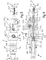
- the device 1 initially has a guide part 2.
- the guide part 2 is with a motor drive or the housing of a motor drive according to the EP 2,393,435 fixed, ie rotationally and axially fixed, connected.
- the definition takes place via the proximal longitudinal slots 2.1a and the annular groove 2.1b of a coupling part 2.1 of the guide part 2 in the manner described there.
- a guide tube 2.2 of the guide part 2 is fixedly connected to the coupling part 2.1, i.e. in a rotationally and axially fixed and non-detachable manner.
- a cylinder jacket-shaped swivel head 2.3 is pivotably arranged on the latter.
- the articulated connection is formed by joints 2.3.1 diametrically opposite one another at the level of a central axis A of the guide tube 2.2 and the first coupling part 2.1.
- a first cylinder jacket 2.1.1 is formed distal to this (also Fig. 4 ), in which at the distal end a pipe connection part 2.1.2 ( Fig. 4 ) is used, with which the guide tube 2.2 is connected, preferably cohesively.
- the mentioned parts 2.1, 2.1.1, 2.1.2 and 2.2 are preferably made of stainless steel, the material connections between the cylinder jacket 2.1.1 and the pipe connection part 2.1.2 in the form of a socket and between the latter and the guide tube 2.2 each through Laser welding are formed.
- an actuating unit 3 is provided to be rotatable to a limited extent and axially movable.
- the actuating unit 3 has for this purpose a second cylinder jacket 3.1 movably surrounding the first cylinder jacket 2.1.1 with an actuating element 3.2 pivotable in the circumferential direction of the axis A in the form of a tab, both of which are integrally formed with one another.
- the second cylinder jacket 3.1 is provided on one side of the actuating element 3.2 with a slot 3.1.1 which extends in the circumferential direction of the second cylinder jacket 3.1 at an angle to the axis A ⁇ 90 °, that is, not perpendicular to the axis A.
- the extension angle of the slot 3.1.1 to the perpendicular to the axis A is only a few degrees, preferably 3 ° to 5 °.
- a pin 2.4 which is firmly connected to the first cylinder jacket 2.1.1, for example in the form of a screwed-in headless slotted screw, protrudes into the slot 3.1.1.
- the slot 3.1.1 thus forms a link guide for the pin 2.4.
- a Luer lock 2.5 is provided on the side of the guide part 2 to enable flushing.
- Short axial slots 3.1a in the cylinder jacket 3.1 of the actuating unit allow a better cleaning option by flushing and contribute to saving weight.
- a ball 3.1.2.2 preloaded by a spring 3.1.2.1 of a spring pin 3.1.2 mounted in the cylinder jacket 3.1 can lock into angular positions determined by the position of the depressions 2.1.1.1.
- an actuating tube 3.3 for the swivel head 2.3 extends axially displaceably.
- the actuating tube 3.3 is fixed at the proximal end, i.e. rotationally and axially fixed with a socket 3.4 ( Fig. 4 ) connected, preferably cohesively, in particular by laser welding.
- the bush 3.4 has two diametrically opposed radial threaded bores 3.4.1 ( Fig. 5 ), into which radial pins 3.4.2 in the form of headless screws are screwed.
- the pins 3.4.2 extend through radial openings 2.1.1.2, which are designed as elongated holes in this area in the first cylinder jacket 2.1.1 in the axial direction, so that the pins 3.4.2 can be axially displaced over a limited distance in these radial openings 2.1.1.2 or are movable and with them the actuating tube 3.3 ( Fig. 5 ). Radially outer ends of the pins 3.4.2 protrude into a radially inwardly directed recess 3.1.3 of the second cylinder jacket 3.1 of the actuation unit 3, which recess corresponds to the transverse dimensions of the pins.
- the actuating tube 3.3 continues at its distal end in a distal tab 3.3.1, which on both sides engages around pins 2.3.2 arranged eccentrically to the joints 2.3.1 on the swivel head 2.3.
- the longitudinal sections of the Fig. 4 , 5 show 2.1.4 magnets 2.1.4 on the outer circumference of the coupling part 2.1 to identify the device connected to the drive (not shown), so that this speed and direction of rotation are automatically adjusted.
- the actuation of the swivel head 2.3 takes place as follows due to the configuration described: If the second cylinder jacket 3.1 is pivoted by a user gripping the tab 3.2 and pivoting the same about the first cylinder jacket 2.1.1 and thus relative to the coupling part 2.1, the second cylinder jacket 3.1 is simultaneously due to the slit 3.1.1 and the pin 2.4 The link guide formed is moved axially in the direction of the axis A. This axial movement is transmitted to the pins 3.4.2 and via these and the sockets 3.4 to the actuating tube 3.3, which is also moved axially in this way.
- a rotation unit 4 is also shown on the left.
- This initially has a second coupling part 4.1 rotatably mounted in the first coupling part 2.1, which at its proximal end has coupling elements in the form of slots coaxial with the axis A and can be coupled to the output shaft of a rotary drive in such a way as in FIG EP 2,393,435 is revealed.
- the second coupling part 4.1 is indeed rotatable in the first coupling part 2.1, in particular via a bearing 4.3, but axially fixed ( Fig. 3 , 5 ). It has distally an axially extending recess 4.4 that is not circularly symmetrical in cross section, for example a square recess, into which the proximal end of a shaft 5.1, such as a drill or milling cutter, is rotatably inserted and inserted from the distal end of the device, i.e. from the swivel head 2.3 can be.
- a shaft 5.1 such as a drill or milling cutter
- the turning tool 5 has for this purpose a shaft 5.1 which is cylindrical over most of its longitudinal extent, but this is designed as a polygon 5.2, in particular a square, at the proximal end corresponding to the recess 4.4.
- a tool head 5.3 for example in the form of a milling or drilling head, is provided at the distal end of the tool 5.
- the axial fixing of the tool 5 takes place via the already mentioned push button 2.1.3, which has an axial breakthrough through which, when the push button 2.1.3 is pressed for inserting and removing the tool 5, the shaft 5.1 including the square 5.2 at its proximal end up to in the recess 4.4 can be pushed through and, when the push button 2.1.3 is relieved, axially fixes the shaft 5.1 over a tapered area 5.4 under the action of the said springs, not shown.
Claims (16)
- Dispositif médical équipé d'une unité de guidage (2) comportant un tube de guidage (2.2) avec un axe longitudinal (A) et une première partie de couplage (2.1) proximale reliée fixement à elle, l'unité de guidage comportant distalement une tête pivotante (2.3) en forme d'enveloppe de cylindre pouvant pivoter par rapport au tube de guidage (2) via des articulations (2.3.1) opposées en diagonale et réalisées au niveau de l'extrémité distale du tube de guidage (2.2), un tube d'actionnement (3.3) relié à la tête pivotante (2.3) pouvant en outre être mobile dans le plan axial dans le tube de guidage (2.2), ledit tube entraînant un pivotement de la tête pivotante par le biais de l'élément de commande (3.2) proximal et l'élément de commande (3.2) pouvant être pivoté autour de l'axe longitudinal (A) et entraînant le pivotement de la tête pivotante (2.3) par coulissement axial du tube d'actionnement (3.3).
- Dispositif selon la revendication 1, caractérisé en ce que le mouvement axial du tube de guidage (2.2) se produit via un guidage à coulisse, avec une fente (3.1.1) s'étendant dans la direction périphérique selon un angle ≠ 90° par rapport à l'axe (A) ainsi que via une tige (2.4) guidée dans ledit tube.
- Dispositif selon la revendication 2, caractérisé en ce que la tige (2.4) est reliée fixement au tube de guidage (2.2) et que la fente (3.1.1) est réalisée au niveau d'une enveloppe de cylindre (3.1) notamment d'un seul tenant, fixement avec l'élément de commande (3.2).
- Dispositif selon l'une quelconque des revendications précédentes, caractérisé en ce que les tiges (3.4.2) s'étendant dans le plan radial sont reliées au tube de guidage (3.3), lesdites tiges s'engrenant respectivement dans une rainure de guidage orientée vers l'intérieur avec sa largeur correspondant au diamètre, dans la direction axiale de l'élément de commande (3.2).
- Dispositif selon la revendication 4, caractérisé en ce que les tiges (3.4.2) agrippent respectivement un trou oblong orienté dans le plan radial et s'étendant dans la direction de l'axe (A) dans une partie reliée fixement au tube de guidage (2.2), notamment une partie de cylindre (2.1.1).
- Dispositif selon l'une quelconque des revendications précédentes, caractérisé en ce que le tube d'actionnement (3.3) doté d'une bride s'engrène de façon excentrée dans une zone proximale de la tête pivotante (2.3) pour le pivotement de celle-ci.
- Dispositif selon l'une quelconque des revendications précédentes, caractérisé par des renfoncements d'arrêt (2.2.1.1) successifs dans la direction périphérique selon un angle différent de 90° par rapport à l'axe (A) dans une partie d'enveloppe de cylindre (2.1.1) reliée au tube de guidage (2.2) et par une tige de ressort (3.1.1) s'engrenant dans celle-ci et reliée à l'élément de commande (3.2).
- Dispositif selon l'une quelconque des revendications précédentes, caractérisé par la présence d'une unité pivotante (4) pouvant tourner par rapport à l'unité de guidage (2).
- Dispositif selon la revendication 8, caractérisé en ce que l'unité pivotante (4) comporte une deuxième partie de couplage (4.1) disposée fixement dans le plan axial mais de façon à pouvoir pivoter dans la première partie de couplage (2.1) .
- Dispositif selon la revendication 8 ou 9, caractérisé en ce que l'unité pivotante (4), notamment la deuxième partie de couplage (4.1), comporte des fentes de couplage (4.2) pour la liaison solidaire en rotation avec un arbre d'entraînement.
- Dispositif selon l'une quelconque des revendications précédentes, caractérisé en ce que la première partie de couplage (2.1) comporte des formes (2.1a, 2.1b) pour la liaison solidaire dans le plan axial et en rotation avec un entraînement et/ou le carter d'un entraînement.
- Dispositif selon l'une quelconque des revendications précédentes, caractérisé par un outil chirurgical tournant (5) pouvant pivoter par rapport à l'unité de guidage et d'actionnement (2, 3) mais pouvant être fixé à elle dans le plan axial.
- Dispositif selon la revendication 12, caractérisé en ce que l'outil tournant (5) comporte au niveau de l'extrémité proximale d'une tige (5.1) une formation (4.4) non cylindrique de préférence carrée pour la mise en prise fixe en rotation dans un évidement non cylindrique de préférence carré correspondant de la deuxième unité de couplage (4.1).
- Dispositif selon la revendication 12 ou 13, caractérisé en ce qu'une tige (5.1) de l'outil (5) s'imbrique avec une zone rétrécie dans le passage d'un élément de libération et de blocage (2.1.3) de la première partie de couplage (2.1).
- Dispositif selon l'une quelconque des revendications précédentes, caractérisé en ce que le tube d'actionnement (3.3) est disposé coaxialement dans le tube de guidage (2.2).
- Dispositif selon l'une quelconque des revendications précédentes, caractérisé en ce que le diamètre extérieur du tube d'actionnement (3.3) correspond au diamètre intérieur du tube de guidage (2).
Applications Claiming Priority (2)
| Application Number | Priority Date | Filing Date | Title |
|---|---|---|---|
| DE102017010033.0A DE102017010033A1 (de) | 2017-10-27 | 2017-10-27 | Medizinische Vorrichtung |
| PCT/EP2018/000412 WO2019081051A1 (fr) | 2017-10-27 | 2018-08-23 | Dispositif médical |
Publications (2)
| Publication Number | Publication Date |
|---|---|
| EP3528688A1 EP3528688A1 (fr) | 2019-08-28 |
| EP3528688B1 true EP3528688B1 (fr) | 2021-07-28 |
Family
ID=63517830
Family Applications (1)
| Application Number | Title | Priority Date | Filing Date |
|---|---|---|---|
| EP18765554.3A Active EP3528688B1 (fr) | 2017-10-27 | 2018-08-23 | Dispositif médical |
Country Status (9)
| Country | Link |
|---|---|
| US (1) | US11331108B2 (fr) |
| EP (1) | EP3528688B1 (fr) |
| JP (1) | JP7228272B2 (fr) |
| KR (1) | KR102589449B1 (fr) |
| CN (1) | CN111212590B (fr) |
| CA (1) | CA3078524C (fr) |
| DE (1) | DE102017010033A1 (fr) |
| ES (1) | ES2892404T3 (fr) |
| WO (1) | WO2019081051A1 (fr) |
Families Citing this family (11)
| Publication number | Priority date | Publication date | Assignee | Title |
|---|---|---|---|---|
| NL2019175B1 (en) * | 2017-07-04 | 2019-01-14 | Fortimedix Surgical B V | Steerable instrument comprising a radial spacers between coaxial cylindrical elements |
| DE102017010033A1 (de) * | 2017-10-27 | 2019-05-02 | Joimax Gmbh | Medizinische Vorrichtung |
| US11364130B2 (en) | 2020-09-01 | 2022-06-21 | Warsaw Orthopedic, Inc. | Spinal implant system and method |
| DE102021115486A1 (de) | 2021-06-15 | 2022-12-15 | Joimax Gmbh | Medizinisches Instrument, medizinisches Instrumentenset, medizinische Vorrichtung und medizinisches Verfahren |
| DE102021119386A1 (de) | 2021-07-27 | 2023-02-02 | Aesculap Ag | Abwinkelbarer Schaft für ein medizinisches Handinstrument |
| DE102022107970A1 (de) | 2022-04-04 | 2023-10-05 | Aesculap Ag | Flexibles chirurgisches Werkzeug mit integrierter Lagerbaugruppe |
| DE102022107972A1 (de) | 2022-04-04 | 2023-10-05 | Aesculap Ag | Medizinisches Werkzeugsystem |
| DE102022119980A1 (de) | 2022-08-09 | 2024-02-15 | Aesculap Ag | Medizinisches Motorhandstück mit Rast- und/oder Anschlageinheit |
| DE102022119983A1 (de) | 2022-08-09 | 2024-02-15 | Aesculap Ag | Medizinisches Motorhandstück mit Winkelstellring und medizinisches Handinstrument |
| DE102022119982A1 (de) | 2022-08-09 | 2024-02-15 | Aesculap Ag | Motorhandstück mit rotierbarem Bedienelement sowie Medizinisches Handinstrument |
| DE102022119979A1 (de) | 2022-08-09 | 2024-02-15 | Aesculap Ag | Medizinisches Motorhandstück für 2-in-1-Bedienung sowie medizinisches Handinstrument mit 2-in-1-Bedienung |
Family Cites Families (32)
| Publication number | Priority date | Publication date | Assignee | Title |
|---|---|---|---|---|
| GB8413058D0 (en) * | 1984-05-22 | 1984-06-27 | Minvade Ltd | Endoscopes |
| US5938616A (en) | 1997-01-31 | 1999-08-17 | Acuson Corporation | Steering mechanism and steering line for a catheter-mounted ultrasonic transducer |
| US5921956A (en) | 1997-09-24 | 1999-07-13 | Smith & Nephew, Inc. | Surgical instrument |
| DE10036108A1 (de) | 1999-09-09 | 2001-11-15 | Tuebingen Scient Surgical Prod | Chirurgisches Instrument für minimal invasive Eingriffe |
| US6312438B1 (en) * | 2000-02-01 | 2001-11-06 | Medtronic Xomed, Inc. | Rotary bur instruments having bur tips with aspiration passages |
| DE10156917B4 (de) | 2001-11-21 | 2006-04-20 | Günter Bissinger Medizintechnik GmbH | Instrument für die endoskopische Chirurgie |
| ATE548067T1 (de) * | 2005-09-16 | 2012-03-15 | Riek Siegfried | Medizinisches instrument |
| DE502007003014D1 (de) * | 2007-07-20 | 2010-04-15 | Wolf Gmbh Richard | Endoskopisches Instrument |
| US8394101B2 (en) * | 2009-02-23 | 2013-03-12 | Globus Medical, Inc. | Discectomy instrument |
| US8568417B2 (en) * | 2009-12-18 | 2013-10-29 | Charles River Engineering Solutions And Technologies, Llc | Articulating tool and methods of using |
| DE202009017470U1 (de) | 2009-12-23 | 2011-02-10 | Joimax Gmbh | Chirurgisches Instrument zur lösbaren Verbindung eines Handstückes mit einem chirurgischen Werkzeug |
| US8348950B2 (en) * | 2010-01-04 | 2013-01-08 | Zyga Technology, Inc. | Sacroiliac fusion system |
| DE102010024136B4 (de) * | 2010-06-17 | 2016-07-07 | Olympus Winter & Ibe Gmbh | Uterusmanipulator mit verstellbarer Portiokappe |
| CN105011893B (zh) * | 2011-02-16 | 2017-07-11 | 奥林巴斯株式会社 | 内窥镜及处理器具 |
| US9119639B2 (en) * | 2011-08-09 | 2015-09-01 | DePuy Synthes Products, Inc. | Articulated cavity creator |
| WO2013082310A1 (fr) * | 2011-12-02 | 2013-06-06 | Barosense, Inc. | Dispositif de positionnement et ensemble articulation pour positionnement à distance d'un outil |
| WO2013090558A1 (fr) | 2011-12-15 | 2013-06-20 | Imricor Medical Systems, Inc. | Poignée compatible avec l'irm et gaine orientable |
| DE102012008970B3 (de) * | 2012-05-03 | 2013-06-27 | Joimax Gmbh | Chirurgische Werkzeugeinrichtung |
| CA3201083A1 (fr) * | 2012-06-20 | 2013-12-27 | Stryker Corporation | Systemes et methodes de manipulation desaxee de tissu |
| US8986225B2 (en) * | 2012-08-02 | 2015-03-24 | Covidien Lp | Guidewire |
| JP6081578B2 (ja) * | 2013-04-01 | 2017-02-15 | テルモ株式会社 | 作動部材、および医療器具 |
| KR102050221B1 (ko) * | 2013-11-29 | 2019-11-29 | 충칭 시산 사이언스 앤드 테크놀로지 컴퍼니 리미티드 | 연속 가변각을 갖는 측방향 연삭 드릴 및 그 구동 구성요소 |
| EP3639767A1 (fr) * | 2014-08-06 | 2020-04-22 | Stryker Corporation | Accessoire de coupe destiné à être utilisé avec une pièce à main chirurgicale électrique |
| WO2016138443A2 (fr) * | 2015-02-26 | 2016-09-01 | Stryker Corporation | Instrument chirurgical doté d'une région d'articulation |
| DE102015204946B4 (de) * | 2015-03-19 | 2017-02-09 | Eberle Gmbh & Co. Kg | Chirurgisches Instrument mit Feinpositioniermechanismus |
| CN109152623A (zh) * | 2016-03-21 | 2019-01-04 | 黄迪熙 | 可拆卸的医疗用切割工具 |
| KR101628648B1 (ko) * | 2016-03-21 | 2016-06-08 | 황적희 | 착탈식 의료용 절삭기구 |
| CN206315109U (zh) * | 2016-08-04 | 2017-07-11 | 彭惠莲 | 一种手术用磨钻 |
| CN206303925U (zh) * | 2016-08-30 | 2017-07-07 | 重庆西山科技股份有限公司 | 新型往复刀具 |
| WO2018129180A1 (fr) * | 2017-01-06 | 2018-07-12 | Dfine, Inc. | Ostéotome avec partie distale pour avancement et articulation simultanés |
| DE102017010033A1 (de) * | 2017-10-27 | 2019-05-02 | Joimax Gmbh | Medizinische Vorrichtung |
| US11510686B2 (en) * | 2018-07-05 | 2022-11-29 | Conmed Corporation | Retrograde drilling device |
-
2017
- 2017-10-27 DE DE102017010033.0A patent/DE102017010033A1/de not_active Withdrawn
-
2018
- 2018-08-23 ES ES18765554T patent/ES2892404T3/es active Active
- 2018-08-23 KR KR1020207012346A patent/KR102589449B1/ko active IP Right Grant
- 2018-08-23 CA CA3078524A patent/CA3078524C/fr active Active
- 2018-08-23 US US16/758,511 patent/US11331108B2/en active Active
- 2018-08-23 JP JP2020522721A patent/JP7228272B2/ja active Active
- 2018-08-23 WO PCT/EP2018/000412 patent/WO2019081051A1/fr unknown
- 2018-08-23 CN CN201880066603.8A patent/CN111212590B/zh active Active
- 2018-08-23 EP EP18765554.3A patent/EP3528688B1/fr active Active
Non-Patent Citations (1)
| Title |
|---|
| None * |
Also Published As
| Publication number | Publication date |
|---|---|
| CA3078524A1 (fr) | 2019-05-02 |
| EP3528688A1 (fr) | 2019-08-28 |
| JP2021500150A (ja) | 2021-01-07 |
| DE102017010033A1 (de) | 2019-05-02 |
| WO2019081051A1 (fr) | 2019-05-02 |
| ES2892404T3 (es) | 2022-02-04 |
| US20200253622A1 (en) | 2020-08-13 |
| KR20200079498A (ko) | 2020-07-03 |
| JP7228272B2 (ja) | 2023-02-24 |
| CN111212590A (zh) | 2020-05-29 |
| CN111212590B (zh) | 2023-11-14 |
| KR102589449B1 (ko) | 2023-10-16 |
| US11331108B2 (en) | 2022-05-17 |
| CA3078524C (fr) | 2024-04-16 |
Similar Documents
| Publication | Publication Date | Title |
|---|---|---|
| EP3528688B1 (fr) | Dispositif médical | |
| DE10358554B4 (de) | Chirurgisches Instrument zum Sezieren von Knochen oder anderem Gewebe mit Teleskopaufsatz | |
| DE3711377C2 (de) | Chirurgisches Instrument | |
| DE19707373C1 (de) | Bajonettkupplung zum lösbaren Verbinden zweier Rohrschaftinstrumente oder -instrumententeile | |
| EP2561816B1 (fr) | Outil pour un instrument chirurgical micro-invasif | |
| EP0634139B1 (fr) | Instrument médical démontable | |
| EP0671149A1 (fr) | Dispositif de pose d'un anneau d'anastomose | |
| DE10255082A1 (de) | Endoskop | |
| DE102008015418A1 (de) | Medizinisches Instrument | |
| EP2389879B1 (fr) | Instrument médical doté d'une poignée amovible | |
| DE202009017470U1 (de) | Chirurgisches Instrument zur lösbaren Verbindung eines Handstückes mit einem chirurgischen Werkzeug | |
| DE102009025487A1 (de) | Selbstfestziehendes Futter mit axialer Arretierung | |
| DE3303335C2 (fr) | ||
| EP1905369B1 (fr) | Tournevis pour la manipulation d'une vis dans un corps humain ou animal | |
| EP1605843B1 (fr) | Dispositif de coupe et de formage | |
| EP1629785B1 (fr) | Pince médicale | |
| DE4323093A1 (de) | Chirurgische Zange | |
| EP3100690A1 (fr) | Instrument pour la chirurgie endoscopique | |
| WO2023194131A1 (fr) | Système d'outil médical | |
| DE202006006914U1 (de) | Medizinisches Instrument | |
| DE202007000427U1 (de) | Chirurgischer Haltegriff und chirurgisches Instrument | |
| DE10328515B4 (de) | Chirurgisches Instrument | |
| EP1491155A1 (fr) | Instrument medical à tige coulissante, en particulier poinçonneuse à tissu | |
| DE202021101150U1 (de) | Medizinisches Instrument und medizinisches Endoskop mit einem solchen Instrument | |
| EP4321107A1 (fr) | Pièce à main motorisée médicale dotée d'une unité d'arrêt et/ou de butée |
Legal Events
| Date | Code | Title | Description |
|---|---|---|---|
| STAA | Information on the status of an ep patent application or granted ep patent |
Free format text: STATUS: UNKNOWN |
|
| STAA | Information on the status of an ep patent application or granted ep patent |
Free format text: STATUS: THE INTERNATIONAL PUBLICATION HAS BEEN MADE |
|
| PUAI | Public reference made under article 153(3) epc to a published international application that has entered the european phase |
Free format text: ORIGINAL CODE: 0009012 |
|
| STAA | Information on the status of an ep patent application or granted ep patent |
Free format text: STATUS: REQUEST FOR EXAMINATION WAS MADE |
|
| 17P | Request for examination filed |
Effective date: 20190524 |
|
| AK | Designated contracting states |
Kind code of ref document: A1 Designated state(s): AL AT BE BG CH CY CZ DE DK EE ES FI FR GB GR HR HU IE IS IT LI LT LU LV MC MK MT NL NO PL PT RO RS SE SI SK SM TR |
|
| AX | Request for extension of the european patent |
Extension state: BA ME |
|
| STAA | Information on the status of an ep patent application or granted ep patent |
Free format text: STATUS: EXAMINATION IS IN PROGRESS |
|
| STAA | Information on the status of an ep patent application or granted ep patent |
Free format text: STATUS: EXAMINATION IS IN PROGRESS |
|
| 17Q | First examination report despatched |
Effective date: 20201125 |
|
| DAV | Request for validation of the european patent (deleted) | ||
| DAX | Request for extension of the european patent (deleted) | ||
| GRAP | Despatch of communication of intention to grant a patent |
Free format text: ORIGINAL CODE: EPIDOSNIGR1 |
|
| STAA | Information on the status of an ep patent application or granted ep patent |
Free format text: STATUS: GRANT OF PATENT IS INTENDED |
|
| INTG | Intention to grant announced |
Effective date: 20210305 |
|
| GRAS | Grant fee paid |
Free format text: ORIGINAL CODE: EPIDOSNIGR3 |
|
| GRAA | (expected) grant |
Free format text: ORIGINAL CODE: 0009210 |
|
| STAA | Information on the status of an ep patent application or granted ep patent |
Free format text: STATUS: THE PATENT HAS BEEN GRANTED |
|
| AK | Designated contracting states |
Kind code of ref document: B1 Designated state(s): AL AT BE BG CH CY CZ DE DK EE ES FI FR GB GR HR HU IE IS IT LI LT LU LV MC MK MT NL NO PL PT RO RS SE SI SK SM TR |
|
| REG | Reference to a national code |
Ref country code: GB Ref legal event code: FG4D Free format text: NOT ENGLISH |
|
| REG | Reference to a national code |
Ref country code: CH Ref legal event code: EP |
|
| REG | Reference to a national code |
Ref country code: DE Ref legal event code: R096 Ref document number: 502018006356 Country of ref document: DE |
|
| REG | Reference to a national code |
Ref country code: AT Ref legal event code: REF Ref document number: 1413947 Country of ref document: AT Kind code of ref document: T Effective date: 20210815 |
|
| REG | Reference to a national code |
Ref country code: IE Ref legal event code: FG4D Free format text: LANGUAGE OF EP DOCUMENT: GERMAN |
|
| REG | Reference to a national code |
Ref country code: NL Ref legal event code: FP |
|
| REG | Reference to a national code |
Ref country code: SE Ref legal event code: TRGR |
|
| PGFP | Annual fee paid to national office [announced via postgrant information from national office to epo] |
Ref country code: IE Payment date: 20210924 Year of fee payment: 4 |
|
| REG | Reference to a national code |
Ref country code: LT Ref legal event code: MG9D |
|
| REG | Reference to a national code |
Ref country code: NO Ref legal event code: T2 Effective date: 20210728 |
|
| PGFP | Annual fee paid to national office [announced via postgrant information from national office to epo] |
Ref country code: NO Payment date: 20210830 Year of fee payment: 4 Ref country code: SE Payment date: 20210921 Year of fee payment: 4 |
|
| PG25 | Lapsed in a contracting state [announced via postgrant information from national office to epo] |
Ref country code: PT Free format text: LAPSE BECAUSE OF FAILURE TO SUBMIT A TRANSLATION OF THE DESCRIPTION OR TO PAY THE FEE WITHIN THE PRESCRIBED TIME-LIMIT Effective date: 20211129 Ref country code: BG Free format text: LAPSE BECAUSE OF FAILURE TO SUBMIT A TRANSLATION OF THE DESCRIPTION OR TO PAY THE FEE WITHIN THE PRESCRIBED TIME-LIMIT Effective date: 20211028 Ref country code: LT Free format text: LAPSE BECAUSE OF FAILURE TO SUBMIT A TRANSLATION OF THE DESCRIPTION OR TO PAY THE FEE WITHIN THE PRESCRIBED TIME-LIMIT Effective date: 20210728 Ref country code: RS Free format text: LAPSE BECAUSE OF FAILURE TO SUBMIT A TRANSLATION OF THE DESCRIPTION OR TO PAY THE FEE WITHIN THE PRESCRIBED TIME-LIMIT Effective date: 20210728 Ref country code: HR Free format text: LAPSE BECAUSE OF FAILURE TO SUBMIT A TRANSLATION OF THE DESCRIPTION OR TO PAY THE FEE WITHIN THE PRESCRIBED TIME-LIMIT Effective date: 20210728 Ref country code: FI Free format text: LAPSE BECAUSE OF FAILURE TO SUBMIT A TRANSLATION OF THE DESCRIPTION OR TO PAY THE FEE WITHIN THE PRESCRIBED TIME-LIMIT Effective date: 20210728 |
|
| REG | Reference to a national code |
Ref country code: ES Ref legal event code: FG2A Ref document number: 2892404 Country of ref document: ES Kind code of ref document: T3 Effective date: 20220204 |
|
| PG25 | Lapsed in a contracting state [announced via postgrant information from national office to epo] |
Ref country code: PL Free format text: LAPSE BECAUSE OF FAILURE TO SUBMIT A TRANSLATION OF THE DESCRIPTION OR TO PAY THE FEE WITHIN THE PRESCRIBED TIME-LIMIT Effective date: 20210728 Ref country code: LV Free format text: LAPSE BECAUSE OF FAILURE TO SUBMIT A TRANSLATION OF THE DESCRIPTION OR TO PAY THE FEE WITHIN THE PRESCRIBED TIME-LIMIT Effective date: 20210728 Ref country code: GR Free format text: LAPSE BECAUSE OF FAILURE TO SUBMIT A TRANSLATION OF THE DESCRIPTION OR TO PAY THE FEE WITHIN THE PRESCRIBED TIME-LIMIT Effective date: 20211029 |
|
| PG25 | Lapsed in a contracting state [announced via postgrant information from national office to epo] |
Ref country code: DK Free format text: LAPSE BECAUSE OF FAILURE TO SUBMIT A TRANSLATION OF THE DESCRIPTION OR TO PAY THE FEE WITHIN THE PRESCRIBED TIME-LIMIT Effective date: 20210728 |
|
| REG | Reference to a national code |
Ref country code: DE Ref legal event code: R097 Ref document number: 502018006356 Country of ref document: DE |
|
| PG25 | Lapsed in a contracting state [announced via postgrant information from national office to epo] |
Ref country code: SM Free format text: LAPSE BECAUSE OF FAILURE TO SUBMIT A TRANSLATION OF THE DESCRIPTION OR TO PAY THE FEE WITHIN THE PRESCRIBED TIME-LIMIT Effective date: 20210728 Ref country code: SK Free format text: LAPSE BECAUSE OF FAILURE TO SUBMIT A TRANSLATION OF THE DESCRIPTION OR TO PAY THE FEE WITHIN THE PRESCRIBED TIME-LIMIT Effective date: 20210728 Ref country code: RO Free format text: LAPSE BECAUSE OF FAILURE TO SUBMIT A TRANSLATION OF THE DESCRIPTION OR TO PAY THE FEE WITHIN THE PRESCRIBED TIME-LIMIT Effective date: 20210728 Ref country code: MC Free format text: LAPSE BECAUSE OF FAILURE TO SUBMIT A TRANSLATION OF THE DESCRIPTION OR TO PAY THE FEE WITHIN THE PRESCRIBED TIME-LIMIT Effective date: 20210728 Ref country code: LU Free format text: LAPSE BECAUSE OF NON-PAYMENT OF DUE FEES Effective date: 20210823 Ref country code: EE Free format text: LAPSE BECAUSE OF FAILURE TO SUBMIT A TRANSLATION OF THE DESCRIPTION OR TO PAY THE FEE WITHIN THE PRESCRIBED TIME-LIMIT Effective date: 20210728 Ref country code: CZ Free format text: LAPSE BECAUSE OF FAILURE TO SUBMIT A TRANSLATION OF THE DESCRIPTION OR TO PAY THE FEE WITHIN THE PRESCRIBED TIME-LIMIT Effective date: 20210728 Ref country code: AL Free format text: LAPSE BECAUSE OF FAILURE TO SUBMIT A TRANSLATION OF THE DESCRIPTION OR TO PAY THE FEE WITHIN THE PRESCRIBED TIME-LIMIT Effective date: 20210728 |
|
| PLBE | No opposition filed within time limit |
Free format text: ORIGINAL CODE: 0009261 |
|
| STAA | Information on the status of an ep patent application or granted ep patent |
Free format text: STATUS: NO OPPOSITION FILED WITHIN TIME LIMIT |
|
| 26N | No opposition filed |
Effective date: 20220429 |
|
| REG | Reference to a national code |
Ref country code: NO Ref legal event code: MMEP |
|
| REG | Reference to a national code |
Ref country code: SE Ref legal event code: EUG |
|
| PG25 | Lapsed in a contracting state [announced via postgrant information from national office to epo] |
Ref country code: SE Free format text: LAPSE BECAUSE OF NON-PAYMENT OF DUE FEES Effective date: 20220824 Ref country code: NO Free format text: LAPSE BECAUSE OF NON-PAYMENT OF DUE FEES Effective date: 20220831 |
|
| PG25 | Lapsed in a contracting state [announced via postgrant information from national office to epo] |
Ref country code: CY Free format text: LAPSE BECAUSE OF FAILURE TO SUBMIT A TRANSLATION OF THE DESCRIPTION OR TO PAY THE FEE WITHIN THE PRESCRIBED TIME-LIMIT Effective date: 20210728 |
|
| PG25 | Lapsed in a contracting state [announced via postgrant information from national office to epo] |
Ref country code: IE Free format text: LAPSE BECAUSE OF NON-PAYMENT OF DUE FEES Effective date: 20220823 Ref country code: HU Free format text: LAPSE BECAUSE OF FAILURE TO SUBMIT A TRANSLATION OF THE DESCRIPTION OR TO PAY THE FEE WITHIN THE PRESCRIBED TIME-LIMIT; INVALID AB INITIO Effective date: 20180823 |
|
| PGFP | Annual fee paid to national office [announced via postgrant information from national office to epo] |
Ref country code: NL Payment date: 20230823 Year of fee payment: 6 |
|
| PGFP | Annual fee paid to national office [announced via postgrant information from national office to epo] |
Ref country code: IT Payment date: 20230831 Year of fee payment: 6 Ref country code: GB Payment date: 20230824 Year of fee payment: 6 Ref country code: ES Payment date: 20230918 Year of fee payment: 6 Ref country code: CH Payment date: 20230902 Year of fee payment: 6 Ref country code: AT Payment date: 20230818 Year of fee payment: 6 |
|
| PGFP | Annual fee paid to national office [announced via postgrant information from national office to epo] |
Ref country code: FR Payment date: 20230821 Year of fee payment: 6 Ref country code: DE Payment date: 20230809 Year of fee payment: 6 Ref country code: BE Payment date: 20230822 Year of fee payment: 6 |