EP2510889B1 - Dispositif de manipulation pour un instrument de chirurgie micro-invasive - Google Patents
Dispositif de manipulation pour un instrument de chirurgie micro-invasive Download PDFInfo
- Publication number
- EP2510889B1 EP2510889B1 EP12002393.2A EP12002393A EP2510889B1 EP 2510889 B1 EP2510889 B1 EP 2510889B1 EP 12002393 A EP12002393 A EP 12002393A EP 2510889 B1 EP2510889 B1 EP 2510889B1
- Authority
- EP
- European Patent Office
- Prior art keywords
- handling device
- proximal end
- coupling
- transmission rod
- rod
- Prior art date
- Legal status (The legal status is an assumption and is not a legal conclusion. Google has not performed a legal analysis and makes no representation as to the accuracy of the status listed.)
- Active
Links
Images


Classifications
-
- A—HUMAN NECESSITIES
- A61—MEDICAL OR VETERINARY SCIENCE; HYGIENE
- A61B—DIAGNOSIS; SURGERY; IDENTIFICATION
- A61B17/00—Surgical instruments, devices or methods, e.g. tourniquets
- A61B17/28—Surgical forceps
- A61B17/29—Forceps for use in minimally invasive surgery
-
- A—HUMAN NECESSITIES
- A61—MEDICAL OR VETERINARY SCIENCE; HYGIENE
- A61B—DIAGNOSIS; SURGERY; IDENTIFICATION
- A61B17/00—Surgical instruments, devices or methods, e.g. tourniquets
- A61B2017/0042—Surgical instruments, devices or methods, e.g. tourniquets with special provisions for gripping
- A61B2017/00455—Orientation indicators, e.g. recess on the handle
-
- A—HUMAN NECESSITIES
- A61—MEDICAL OR VETERINARY SCIENCE; HYGIENE
- A61B—DIAGNOSIS; SURGERY; IDENTIFICATION
- A61B17/00—Surgical instruments, devices or methods, e.g. tourniquets
- A61B2017/0046—Surgical instruments, devices or methods, e.g. tourniquets with a releasable handle; with handle and operating part separable
-
- A—HUMAN NECESSITIES
- A61—MEDICAL OR VETERINARY SCIENCE; HYGIENE
- A61B—DIAGNOSIS; SURGERY; IDENTIFICATION
- A61B17/00—Surgical instruments, devices or methods, e.g. tourniquets
- A61B17/28—Surgical forceps
- A61B17/29—Forceps for use in minimally invasive surgery
- A61B2017/2901—Details of shaft
- A61B2017/2902—Details of shaft characterized by features of the actuating rod
- A61B2017/2903—Details of shaft characterized by features of the actuating rod transferring rotary motion
-
- A—HUMAN NECESSITIES
- A61—MEDICAL OR VETERINARY SCIENCE; HYGIENE
- A61B—DIAGNOSIS; SURGERY; IDENTIFICATION
- A61B17/00—Surgical instruments, devices or methods, e.g. tourniquets
- A61B17/28—Surgical forceps
- A61B17/29—Forceps for use in minimally invasive surgery
- A61B17/2909—Handles
- A61B2017/2912—Handles transmission of forces to actuating rod or piston
- A61B2017/2919—Handles transmission of forces to actuating rod or piston details of linkages or pivot points
- A61B2017/292—Handles transmission of forces to actuating rod or piston details of linkages or pivot points connection of actuating rod to handle, e.g. ball end in recess
-
- A—HUMAN NECESSITIES
- A61—MEDICAL OR VETERINARY SCIENCE; HYGIENE
- A61B—DIAGNOSIS; SURGERY; IDENTIFICATION
- A61B17/00—Surgical instruments, devices or methods, e.g. tourniquets
- A61B17/28—Surgical forceps
- A61B17/29—Forceps for use in minimally invasive surgery
- A61B2017/2926—Details of heads or jaws
- A61B2017/2927—Details of heads or jaws the angular position of the head being adjustable with respect to the shaft
- A61B2017/2929—Details of heads or jaws the angular position of the head being adjustable with respect to the shaft with a head rotatable about the longitudinal axis of the shaft
- A61B2017/293—Details of heads or jaws the angular position of the head being adjustable with respect to the shaft with a head rotatable about the longitudinal axis of the shaft with means preventing relative rotation between the shaft and the actuating rod
Definitions
- the present invention relates to a handling device for a micro-invasive-surgical instrument, a micro-invasive-surgical instrument and in particular to features for coupling a shaft and a transmission rod with the handling device.
- micro-invasive surgical instruments include a long and thin shaft, a tool at the distal end of the shaft and a handling device at the proximal end of the shaft.
- the tool includes, for example, a barrel, dissecting, biopsy or other forceps, a pair of scissors or a needle holder with at least two straight or curved jaws, cutting or other jaws, at least one of which is movable.
- the tool comprises another active device, for example a manipulator with a finger or a finger-shaped device or an electrode in hook shape or in another shape.
- the shaft contains (at least) a transmission rod, which is usually arranged in a closed channel in the interior of the shaft.
- the handling device comprises one or more relative to each other movable actuators, such as two handle parts that can move medical personnel with one hand relative to each other.
- the proximal end and the distal end of the transmission rod are coupled to the actuator and to the tool, respectively, such that force exerted by the medical personnel on the actuators or relative movement of the actuators caused by medical personnel is transmitted to the tool, such as jaws to move towards each other or to compress.
- the tool and a part of the shaft are introduced, for example, through a natural or artificial body opening into a natural or artificial cavity in the body of a patient.
- the development of microinvasive surgical techniques is to use ever smaller and, above all, fewer and fewer approaches.
- instruments with curved shanks can be used.
- an instrument with a curved shaft can not readily be rotated about its longitudinal axis within the access to alter the orientation of the tool at its distal end.
- a medical instrument with a curved shaft.
- a jaw part is detachably connected to a shaft by means of a bayonet closure. In the connected state, the jaw part is rotatable relative to the shaft.
- the shaft is detachably connected to a handle.
- a handwheel which is rotatably connected to an outer shaft tube, the curved shaft can be rotated relative to the handle.
- An inner tube is connected to another handwheel on the handle.
- the instrument can be designed as a unipolar or bipolar RF instrument.
- a surgical instrument with a mouth unit, a shaft and a handle unit.
- the jaw unit is releasably attached to the end of a shaft tube of the shaft and rotatable relative thereto.
- the tool, shank and handling device of a micro-invasive-surgical instrument should be separable from one another and connectable to one another without the use of auxiliary means, in order to allow a simple and thorough cleaning of the instrument.
- auxiliary means for example, from the DE 10 2006 038 516 A1 It is known to form the tool and the distal end of the shaft so that the tool can be mounted and disassembled in an open-open mounting position on the shaft.
- some aspects of both the coupling of the tool with the shaft and the coupling of the shaft with the handling device have not been solved completely satisfactory.
- WO 2010/064050 A1 discloses a handling device having the features of the preamble of claim 1.
- An object of the present invention is to provide an improved handling device for a micro-invasive surgical instrument and an improved micro-invasive surgical instrument.
- Embodiments of the present invention are based on the idea of providing, in a handling device, an orientation device which makes it possible to insert the proximal end of a shaft with a non-rotationally symmetrical proximal end of a transmission rod without regard to its orientation in the handling device.
- the orientation device is designed so that a with respect to a rotation about its longitudinal axis arbitrarily introduced proximal end of a transmission rod in a predetermined orientation or in one of several predetermined orientations transferred, in particular rotated or rotated.
- the orientation device with respect to the original orientation of the proximal end of the transmission rod one or more dead points. Between these dead centers, however, there are one or more large angular ranges, within which the proximal end of the transmission rod can originally be arbitrarily oriented and then transferred by the orientation device into one or one of a plurality of predetermined orientations.
- a manipulator for a micro-invasive surgical instrument comprises a handle means for manually holding and guiding the manipulator, a shaft coupling for releasably mechanically coupling the manipulator to a proximal end of a shaft, a rod coupling for slidable mechanical coupling in the manipulator at least one of displaceable or rotatable proximal end of a transmission rod which is at least either displaceable or rotatable in a shaft coupled to the shaft coupling, and orienting means for rotating a proximal end of a transmission rod inserted into the handling device into a predetermined orientation or one of a plurality of predetermined orientations.
- the rod coupling is displaceable in particular between a predetermined distal mounting position and a working range of positions arranged proximally of the predetermined mounting position.
- the predetermined working range may be extended, in particular extended over several millimeters. Alternatively, the working range may be small or, within the achievable or used precision, comprise only one position.
- further mounting positions can be provided within a particular contiguous interval or area (mounting area).
- the rod coupling is in particular mechanically coupled to a manually movable actuating device of the handling device in order to transmit a manual translational or rotational movement of the actuating device and a manually applied to the actuator force and / or by a manually applied to the actuator torque on the transmission rod by means of which the Movement and the force or torque are transmitted to the distal end of the transmission rod.
- the rod coupling is in particular designed so that they can receive or release a proximal end of a transmission rod in the mounting position and hold in positions within the work area a proximal end of a transmission rod low backlash and in particular positive and / or non-positive.
- the proximal end of a transmission rod for which the handling device is provided and formed may have a constant cross-section within a predetermined range.
- a torque between the orientation device and / or rod coupling on the one hand and the proximal end of the transmission rod on the other hand can be positively transmitted.
- a translational movement and a corresponding force can be transmitted between the rod coupling and the proximal end of the transmission rod in a frictionally engaged manner.
- a compressive force or a thrust force in the distal direction can also be transferred to the proximal end of the transmission rod in a form-fitting manner.
- the proximal end of the transmission rod When the proximal end of the transmission rod has a non-constant cross-section in the region provided for placement in the rod coupling, translational movement and corresponding force may alternatively or additionally be positively transferred between the rod coupling and the proximal end of the transmission rod.
- the proximal end of the transmission rod has one or more undercuts and / or recesses into which the rod coupling can engage.
- the rod coupling is displaceable in particular parallel to a longitudinal axis of a shaft coupled or to be coupled to the handling device.
- the rod coupling is rotatable about a longitudinal axis of a shaft coupled or to be coupled to the handling device.
- the transmission rod is flexurally flexible.
- the transmission rod is stiff or inelastic, in particular in the longitudinal direction and / or with respect to torsion.
- the orientation device is in particular arranged distally upstream as a separate component of the rod coupling.
- the orientation device may be part of the rod coupling, wherein it is arranged in particular on its distal side.
- the orientation device is in particular designed to rotate a proximal end of a transmission rod arbitrarily oriented with respect to rotation about its longitudinal axis within one or more predetermined angular ranges in the predetermined orientation or in one of a plurality of predetermined orientations upon insertion into the handling device. Between the predetermined angular ranges can be dead points, which may have a certain extent in practice.
- the orientation device may be configured so that the dead points are smaller or substantially smaller than the predetermined angular ranges between the dead centers.
- the handling device and the orientation device are in particular designed such that the proximal end of a pull rod can be introduced into the handling device in a direction parallel to its longitudinal axis.
- a transmission rod or a proximal end of a shaft or a transmission rod is meant in particular the axis to which the object in question is rotationally symmetric or substantially rotationally symmetrical.
- these statements relate in particular to their ends, which are usually at least partially straight or not curved.
- the proximal end of the pull rod may be releasably mechanically coupled to the rod coupling, respectively.
- the orientation device can significantly simplify the handling of an entire micro-invasive-surgical instrument, in particular during the assembly or mechanical connection or coupling of the components. Medical or other personnel may - particularly after mounting a tool at the distal end of a shaft - insert the shaft with the transmission rod without regard to the orientation of the proximal end of the transmission rod in the handling device. If the orientation of the proximal end of the transmission rod happens to be at a dead center, this can easily be felt, since the stem can not be inserted to the intended position in the handling device. In this case, a rotation of the shaft and transmission rod is sufficient to almost any small angle, and the assembly can be continued and completed. Shaft and transmission rod can thus be introduced quickly and without visual control in the handling device. The handling device described here can thus improve the efficiency and productivity of the staff. The concentration of medical personnel on a secondary activity is no longer necessary and can be of greater benefit to the patient and his treatment.
- the orientation device has a passage opening which extends from distal to proximal, wherein the cross section of the passage opening varies continuously from distal to proximal at least in sections.
- the cross section of the passage opening narrows in particular from distal to proximal.
- the passageway receives the proximal end of a transmission rod, particularly in any orientation.
- the cross-section of the through-opening varies such that a proximal end of a transmission rod has an arbitrary orientation, originally within a predetermined angular range, upon movement from distal to proximal into a predetermined orientation is rotated.
- the cross section of the through opening varies in particular continuously or in sections continuously.
- the through-opening of the orientation device has, in particular, a sliding surface which is not parallel to the direction in which a shaft and a transmission rod are to be introduced into the handling device.
- a sliding surface which is not parallel to the direction in which a shaft and a transmission rod are to be introduced into the handling device.
- a plurality of sliding surfaces are provided.
- Each sliding surface may be planar or helical in order to cause rotation of a proximal end of a transmission rod from distal to proximal in the passage opening into a predetermined orientation or one of a plurality of predetermined orientations.
- the orientation device has two flat sliding surfaces in the passage opening, as a result of which the passage opening narrows wedge-shaped from distal to proximal.
- the distance between the two sliding surfaces is chosen in particular at the distal end of the passage opening such that the proximal end of a transmission rod can be introduced into the passage opening in any orientation at the distal end.
- the two sliding surfaces in particular have a spacing which is selected such that a proximal end of a transmission rod can be passed completely through the through-opening only in two predetermined orientations differing by 180 °.
- the passage opening may alternatively be formed at the distal end such that the proximal end of a transmission rod can be inserted into the passageway only at one orientation within one or more angular ranges, with a proximal end of a transmission rod having an orientation within one or more smaller, predetermined ones Dead areas can not be inserted into the through hole.
- Sliding surfaces in particular flat and wedge-shaped sliding surfaces, can be easily produced means for automatic rotation of a proximal end of a transmission rod in a predetermined orientation, which achieve a reliable effect at low production costs.
- the orientation device may be displaceable relative to the rod coupling between a predetermined distal mounting position and a predetermined proximal working position.
- the orientation device is displaceable in a direction parallel to the longitudinal axis of a proximal end of a transmission rod inserted or to be introduced into the handling device.
- a displaceable orientation device can assume or have additional functions and thus promote a simple and compact construction of the handling device.
- a handling device with an orientation device which is displaceable between a mounting position and a working position, may be configured such that the orientation device holds the rod coupling locked in the predetermined proximal working position.
- the rod coupling is displaceable, in particular, between a distal assembly position and a working region or range of working positions lying proximal to the assembly position, in particular parallel to the direction in which the orientation device is displaceable.
- the handling device is designed such that the orientation device restricts the displaceability of the rod coupling to the working area in the predetermined proximal working position.
- the orientation device restricts the working area, in particular, in that the rod coupling in the extremely distal position within the working area is just in contact with the orientation device in its predetermined proximal working position.
- a handling device with an orientation device displaceable between a mounting position and a working position may further comprise a shaft locking device for locking a shaft to the shaft coupling, wherein the handling device is configured such that a shaft locked to the shaft coupling by the shaft locking device forms the orientation device in the shaft predetermined proximal working position holds in which the orientation device locks the rod coupling.
- the proximal end of the shaft held in a predetermined position by means of the shaft locking device strikes against a distal side of the orientation device and thus keeps it in the predetermined proximal working position.
- the shaft locking device can thus not only hold the shaft directly in a predetermined position on the shaft coupling, but at the same time indirectly hold the rod coupling locked via the orientation device.
- the rod coupling in particular comprises a movable jaw for holding a proximal end of a transmission rod, wherein the rod coupling is formed so that the jaw at a predetermined mounting position of the rod coupling receive or release a proximal end of a transmission rod and in a predetermined operating range of positions of the rod coupling can hold a proximal end of a transmission rod.
- the rod coupling comprises two or more symmetrically arranged gripping jaws.
- the rod coupling comprises only one gripping jaw or an asymmetrical arrangement of gripping jaws.
- Each jaw is in particular pivotable about an associated axis between a mounting position and a holding position. In the mounting position of the jaw or in the mounting positions of the jaws, a proximal end of a transmission rod can be inserted into the rod coupling and removed therefrom. In the holding position of the gripping jaw or in the holding positions of the gripping jaw, a proximal end of a transmission rod can be held positively and / or non-positively or frictionally by the gripping jaw or gripping jaws.
- the gripping jaw or jaws are configured to include a claw or section of enlarged cross-section at the proximal end of a transmission rod for positive engagement with the proximal end to form the transmission rod.
- the jaw may have a concave portion into which a corresponding convex portion may engage the proximal end of the transmission rod.
- the gripping jaw or jaws may be configured to engage in a taper or concave area at or near the proximal end of the transmission rod to form a positive connection with the proximal end of the transmission rod.
- both the jaw or the jaws and the proximal end of the transmission rod may each have a convex portion (or plural convex portions) and a concave portion (or concave portions) each having a convex portion formed on the jaw member to engage a concave portion at the proximal end of the transmission rod, and wherein a respective convex portions at the proximal end of the transmission rod is formed to engage in a concave portion on the jaw.
- the handling device may further comprise a guide pin and a cam groove, wherein either the guide pin or the cam groove is disposed on the jaw and wherein the guide pin engages the cam groove to hold the jaw in different positions depending on the position of the rod coupling.
- the guide pin and the cam groove are formed and arranged so that the jaw in the mounting position of the rod coupling pivoted away from the intended position of a proximal end of a transmission rod and pivoted in positions in the predetermined working area to the proximal end of the transmission rod and with the transmission rod in a form-fitting Connection is.
- the control groove on the handling device in the direction of the displaceability of the rod coupling are immovable and arranged the guide pin on the jaw.
- the control groove can be rotatable with the entire rod coupling and optionally with the orientation device, in particular around the longitudinal axis of a proximal end of a transmission rod inserted or to be inserted into the rod coupling.
- each gripping jaw has one or more guide pins.
- the gripping jaw or each jaw of several gripping jaws has in particular two opposite guide pins, which engage in opposite and parallel control grooves.
- the orientation device is rotatable in particular relative to the handling device about an axis, wherein the orientation device is further configured to transmit a torque to a coupled to the rod coupling transmission rod.
- the orientation device is rotatable about a longitudinal axis of a proximal end of a shaft or a proximal end of a transmission rod in the shaft used in the handling device.
- the orientation device is formed in a form-fitting manner, in particular at its proximal end, with the proximal end of the intended transmission rod.
- the proximal end of the transmission rod has a flattening with two parallel surfaces at a predetermined distance
- the orientation device has at its proximal end two opposite surfaces with the predetermined distance or a slightly greater distance.
- the orientation device is in particular indirectly or directly coupled to a rotary wheel or another actuating device on the handling device, by means of which the orientation device and thus a transmission rod of a shaft inserted into the handling device can be rotated or a torque can be transmitted to it.
- orientation device Several functions can thus be integrated into the orientation device, in particular the automatic rotation of a proximal end of a transmission rod in a predetermined orientation, the locking of the rod coupling and the transmission of a torque to an inserted transmission rod.
- This integration or realization of multiple functions in the orientation device enables a particularly simple, cost-effective, compact and robust construction of the handling device.
- a micro-invasive surgical instrument includes a handling device as described herein, a shaft having a proximal end adapted for releasable coupling to the handling device, and a distal end mechanically connected or connectable to a tool, and a transmission rod for transmitting at least one of a force and a torque from the handling device to the distal end of the shaft, the transmission rod having at its proximal end a non-rotationally symmetrical shape corresponding to the shape of the orientation device.
- the stem of the micro-invasive surgical instrument may be straight or curved, rigid or flexible.
- the transmission rod is flexible in sections, in particular.
- the tool comprises in particular a barrel, dissecting, biopsy or other forceps, a pair of scissors or a needle holder with at least two straight or curved jaws, cutting or other jaw parts, of which at least one or one is movable.
- the tool comprises, for example, a manipulator with a finger or a finger-shaped device or an electrode in a hook shape or in another shape.
- the transmission rod is designed in particular for transmitting a tensile and / or thrust force to the tool at the distal end of the shaft.
- the transmission rod can be designed to transmit a torque and a rotational movement to the tool.
- the proximal end of the transmission rod has a shape that corresponds to a passage opening or to a proximal end of a passage opening in the orientation device.
- a micro-invasive surgical instrument as described herein includes a tool at the distal end of the shaft, the tool comprising a curved jaw member.
- the tool comprises two or more curved jaw parts. If a curved jaw part is pivotable about a pivot axis, it is in particular curved in a plane perpendicular to the pivot axis or in a plane parallel to the pivot axis or in both directions.
- Arched or even helically curved jaws, blades or other jaws of micro-invasive surgical instruments are particularly suitable for some applications.
- a rotation of more than 90 degrees up to 180 degrees
- a rotatability of a tool with one or more curved jaw parts about a longitudinal axis of a shaft of a tool can therefore be particularly advantageous.
- FIG. 1 3 shows a schematic representation of a micro-invasive surgical instrument 10 having a distal end 11 and a proximal end 12.
- the micro-invasive surgical instrument 10 comprises a tool 20, a shaft 30 and a handling device 50.
- the tool 20 has a first movable jaw part 25 and a second movable jaw part 26 on.
- the jaws 25, 26 are in FIG. 1 in solid lines in open positions 252, 262 and in dashed lines in closed positions 251, 261 shown.
- the jaw parts 25, 26 may each be straight or substantially straight or in the direction perpendicular to the plane of the drawing of the FIG. 1 and / or - deviating from the illustration in FIG FIG. 1 - in the drawing plane of the FIG. 1 be curved.
- the proximal end 22 of the tool 20 is releasably mechanically coupled to a distal end 31 of the shaft 30.
- the shaft 30 is in FIG. 1 greatly shortened and just shown for the sake of simplicity. Deviating from the illustration in FIG. 1 the shaft 30 may be flat or spatially curved. With a spatially curved shape of the shaft 30 within a plane, or more preferably for some applications, the microinvasive surgical instrument 10 may be particularly suitable for microinvasive surgical procedures in which an endoscope and one or more instruments simultaneously through a single access in a body cavity are introduced.
- the proximal end 32 of the shaft 30 is releasably mechanically coupled to the distal end 51 of the handling device 50.
- the handling device 50 has a rotary wheel 57, a first grip part 58 and a second grip part 59.
- the rotary wheel 57 is provided for controlling a rotation of the tool 20, in particular of the jaw parts 25, 26, about a longitudinal axis 29.
- the rotary wheel 57 is rotatable about an axis 578, which is at the same time the longitudinal axis of the shaft 30 at its proximal end 32.
- the axis 578 may be parallel to the longitudinal axis of the shaft 30 at its proximal end 32.
- the rotary wheel 57 has a surface structure that enables reliable operation even with gloves, for example, the indicated webs in the axial direction.
- the grip parts 58, 59 are in particular - deviating from the in FIG. 1 shown highly stylized shape - arranged and shaped so that medical personnel with one hand grip both gripping parts 58, 59 fatigue and move relative to each other.
- At least one of the two grip parts 58, 59 is movable relative to the other components of the handling device 50.
- the first grip part 58 is rigid and the second grip part 59 is movably arranged.
- the second grip part 59 is in particular between a first, in FIG. 1 shown in dashed line working position 591 and a second, in FIG. 1 shown in solid line Working position 592 movable.
- the second grip part 59 of the handling device 50 is mechanically coupled to the jaw parts 25, 26 of the tool 20 such that the jaw parts 25, 26 are in their closed positions 251, 261 when the second grip part 59 assumes its first working position 591, and the jaw parts 25, 26 are in their open positions 252, 262 when the second grip part 59 assumes its second working position 592.
- FIG. 2 shows a schematic representation of components or components of the above with reference to FIG. 1 shown micro-invasive-surgical instrument 10, which can be assembled or assembled to the instrument without the use of tools. Likewise, the micro-invasive-surgical instrument 10 without tools in the in FIG. 2 separated components or components are disassembled. By the whole FIG. 2 continuous dot-dash line 19 indicates how these components or components are to be assembled.
- the tool 20 is in particular permanently connected to a transmission rod 40, which is provided for transmitting a force and a torque from the handling device 50 to the tool 20.
- a transmission rod 40 which is provided for transmitting a force and a torque from the handling device 50 to the tool 20.
- This in FIG. 2 not shown distal end of the transmission rod 40 is coupled to the jaw members 25, 26 such that a movement of the transmission rod 40 parallel to the longitudinal axis 29 of the tool 20 causes a synchronous movement of the jaws 25, 26.
- FIG. 2 Not shown bayonet coupling means and coupled to the transmission rod 40 locking device provided.
- the jaws 25, 26 are in FIG. 2 in solid lines in overhead positions 253, 263 and in dashed lines in the already above with reference to FIG. 1 described closed and open positions 251, 252, 261, 262 shown.
- the jaw members 25, 26 are in the open-top positions 253, 263, which is coupled to the jaws 25, 26 and the distal end of the transmission rod 40 and in FIG. 2 not shown locking device inactive.
- the transmission rod 40 can be inserted into a provided for the transmission rod 40 channel 34 in the shaft 30 and the proximal end 22 of the tool and the distal end 31 of the shaft beyond the in FIG. 2 not shown bayonet coupling devices are releasably mechanically connected or coupled. Furthermore, in this unlocked state, a mechanical coupling of the proximal end 22 of the tool 20 and the distal end 31 of the shaft 30 over the in FIG. 2 not shown bayonet coupling devices are solved.
- the locking device coupled to the distal end of the transmission rod 40 and indirectly to the jaw members 25, 26 is in FIG a work item or in a position within a workspace.
- the mechanical coupling of the proximal end 22 of the tool 20 with the distal end 31 of the shaft 30 on the in FIG. 2 Not shown bayonet coupling devices locked. If the mechanical connection or coupling of the tool 20 and shaft 30 is locked, the tool 20 and the shaft 30 can not or can not be easily separated from one another without destruction.
- the proximal end 22 of the tool 20 and the distal end 31 of the shaft 30 may comprise other coupling means.
- a locking device on the tool 20 is provided which locks the mechanical connection of the tool 20 and shaft 30 when the jaw members 25, 26 are in the overhead positions 253, 263.
- the handling device 50 has an in FIG. 2 indicated by a dotted line recess 503.
- the second handle part 59 is first in a in FIG. 2 shown in a solid line coupling position 593 brought.
- the second handle part 59 is in the coupling position 593, there is an in FIG. 2 Not shown rod coupling inside the handling device 50 in a coupling position in which they can receive or release the proximal end 42 of the transmission rod 40.
- the in FIG. 2 not shown rod coupling in the interior of the handling device 50 mechanically connected or coupled to the proximal end 42 of the transmission rod 40.
- the second grip part 59 moves depending on the positions of the jaws 25, 26 (closed positions 251, 261, open positions 252, 262 or therebetween) in the first working position 591, the second working position 592 or a position between the first working position 591 and the second working position 592 over.
- the micro-invasive-surgical instrument 10 As in FIG. 1 configured.
- the jaw parts 25, 26 can be moved between the closed positions 251, 261 and the open positions 252, 262.
- the jaws 25, 26, are rotated about the longitudinal axis 29 of the tool 20.
- the shaft 30 near its proximal end 32 may include another rotary wheel disposed near the distal end 51 of the handling device 50 when the proximal end 32 of the shaft 30 is inserted into the handling device 50.
- the shaft 30 can be rotated about the longitudinal axis of the proximal end 20 of the shaft 30. This is of particular importance when the shaft 30 deviating from the illustrations in the Figures 1 and 2 is curved. In this case, the curved shaft 30 and the tool 20 at the distal end 31 of the curved shaft 30 can be rotated independently of each other.
- the tool 20 may have another means of action, in particular a manipulator, such as a finger-shaped manipulator, or an electrode, for example a hook-shaped electrode.
- a manipulator such as a finger-shaped manipulator
- an electrode for example a hook-shaped electrode
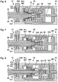
- FIG. 3 shows a schematic representation of a section through an embodiment of the handling device 50 of the above with reference to Figures 1 and 2 microinvasive surgical instrument shown.
- the illustrated section plane is parallel to the drawing planes of the Figures 1 and 2 and contains those already in the Figures 1 and 2 indicated axis 578.
- the in the Figures 1 and 2 shown grip parts 58, 59 are in FIG. 3 Not shown.
- the handling device 50 comprises a housing 501 with the recess 503 extending from the distal end 51 of the handling device 50, which is already in FIG. 2 is indicated.
- the surface of the recess 503 is designed essentially as a circular-cylindrical guide surface 530 that is symmetrical to the axis 578.
- a proximal end 32 of a shaft 30 and a proximal end 42 of a transmission rod 40 arranged in the shaft 30 are shown in FIG FIG. 3 partially inserted into the recess 503 shown.
- Some components or elements of the handling device 50 which in the Figures 3 and 6 to 8 are each shown in one piece, because they each form in the handling device 50 for themselves rigid mechanical units, can be composed of several form-fitting, non-positive or cohesively joined elements differing from the representations - for manufacturing reasons, for example.
- the handling device 50 comprises a shaft coupling 53.
- the shaft coupling 53 is formed by the guide surface 530 and a locking device for locking the shaft 30 in the handling device 50.
- the locking device comprises a latch 531 which extends substantially transverse to the axis 578 and is linearly displaceable transversely to the axis 578 within a predetermined range.
- the latch 531 has a collar 534 in a cavity in the housing 501 of the handling device 50, wherein the shape of the collar 534 and the Shape of the cavity limit the linear displacement of the bolt 531.
- the latch 531 has an unlocking button 538 which projects beyond the outer contour of the housing 501 of the handling device 50.
- the latch 531 has an opening 532 which is adapted to the outer contour of the cross section of the shaft 30.
- a spring 533 between a shoulder on the housing 501 of the handling device 50 and a shoulder on the latch 531 pushes the latch 531 in the in FIG. 3 shown position.
- the latch 531 By pressing the release button 538 or by acting on the shaft 30 on the edge of the opening 532 in the latch 531, the latch 531 can be displaced linearly against the force of the spring 533 up to a position in which the edge of the opening 532 in FIG Latch 531 no longer protrudes into the recess 503. In this position of the bolt 531, the shaft 30 can be inserted into the recess 503 or removed therefrom.
- the handling device 50 further comprises a control and orientation device 54, hereinafter referred to as orientation device, and a rod coupling 55 within the substantially drum-shaped rotary wheel 57.
- the orientation device 54 and the rod coupling 55 are designed to rotate together with the rotary wheel 57 about the axis To be turned 578.
- the orientation device 54 and the rod coupling 55 are therefore rigidly connected to the rotary wheel 57 with respect to rotation about the axis 578.
- both the orientation device 54 and the rod coupling 55 are displaceable within the handling device and relative to the rotary wheel 57 in the axial direction or parallel to the axis 578 in each case within a predetermined range.
- the orientation device 54 comprises a slider 541, which in FIG. 3 is shown in a distal mounting position 546. Between a collar of the slider 541 and the rotary wheel 57, a spring 542 is arranged, which holds the slider 541 elastically in the mounting position 546.
- the slider 541 and the rotary wheel 57 have, in particular at the proximal end of the slider 541 in the vicinity of a proximal end face 549 of the slider 541 surfaces which bear against each other and not rotationally symmetrical to Axis 578 are. Thereby, the slider 541 is held in a predetermined orientation relative to the rotary wheel 57 regardless of its position in the axial direction with respect to the rotation about the axis 578.
- the rod coupling 55 comprises two gripping jaws 551 which are arranged symmetrically with respect to the axis 578 and which are articulated by means of joints 552 on a power transmission component 565.
- Each jaw 551 has a recess 553 with a shape that corresponds to the shape of a claw 45 at the proximal end 42 of the transmission rod 40, on.
- each gripping jaw 551 has a guide pin 554 whose axis is perpendicular to the cutting plane of the FIG. 3 is.
- Each end of each of the guide pins 554 engages with an associated cam groove 555 in the dial 57. Except the two in FIG. 3 shown control grooves 555 behind the cutting plane of the FIG. 3 are two in FIG.
- control grooves provided on the rotary 57 with respect to the cutting plane of the FIG. 3 to the in FIG. 3 shown control grooves 57 are mirror-symmetrical.
- the control grooves 555 are curved at least in sections. In a linear displacement of the joints 552 of the jaws 551 parallel to the axis 578 cause the control grooves 555 pivotal movements of the jaws 551, the below with respect to the FIGS. 6 to 8 to be discribed.
- a rod 561 and a cup-shaped component 562 are further arranged.
- the rod 561 and the cup-shaped component 562 are rigidly connected to one another and displaceable parallel to the axis 578 within the rotary wheel 57.
- a compression spring 564 is arranged between a radially inwardly projecting collar 563 of the cup-shaped member 562 and a radially outwardly projecting collar of the power transmission member 565.
- the compression spring 564 limits a tensile force which can be transmitted from the rod 561 via the cup-shaped component 562, the compression spring 564, the power transmission component 565 and the gripping jaws 551 to a proximal end 42 of a transmission rod 40 coupled to the gripping jaws 551.
- proximal end of the rod 561 is - for example by means of a connecting rod - so with the above based on the Figures 1 and 2 illustrated second handle part 59, pivotal movement of the second handle portion 59 causes linear movement of the rod 561 and the rod coupling 55 parallel to the axis 578.
- FIGS. 4 and 5 each show a section along the left in FIG. 3 indicated section plane AA, in the middle and right cuts along the planes BB and CC, which in the FIGS. 4 and 5 on the left in the representations of the sections along the planes AA are indicated.
- the sectional plane AA is perpendicular to the in FIG. 3 Axis 578 shown in FIG. 3.
- the sectional planes BB and CC each contain the axis 578. All sectional planes AA, BB and CC are perpendicular to each other.
- both in the FIGS. 4 and 5 illustrated embodiments of the slider 541 each have a passage opening 543.
- each distal portion shown on the left is the surface of the through hole 543 formed as a sectionally conical abutment surface 544 for the proximal end 32 of the shaft 30.
- the contact surface 544 is rotationally symmetrical with respect to the axis 578 or substantially rotationally symmetrical and to the shape of the proximal end 32 of the in FIG. 3 Shaft 30 shown adapted.
- the sliding surfaces 545 define at their distal edges an approximately square cross-section of the through-hole 543.
- the sliding surfaces 545 define a narrow rectangular cross-section which matches the cross-section of the claw 45 of FIG FIG. 3 shown proximal end 42 of the transmission rod 40 is adjusted.
- FIG. 4 The cross-section of the claw 45 at the proximal end 42 of the transmission rod in the in FIG. 3 shown Orientation shown. This orientation of the proximal end 42 and the claw 45 does not correspond to the orientation predetermined by the cross section of the through opening 543 at the proximal edges of the sliding surfaces 545.
- FIG. 4 in the middle and on the right in the sections along the planes BB and CC, the proximal end 42 of the transmission rod is shown with the claw 45 in the orientation defined by the cross section of the through-hole 543 at its proximal end.
- the distal end 42 of the transmission rod 40 is not tightly guided in the direction parallel to the sectional plane BB and perpendicular to the axis 578.
- section along the plane CC it can be seen that the distal end 42 of the transmission rod 40 in the direction parallel to the sectional plane CC and perpendicular to the axis 578 abuts the slider 541, whereby the orientation of the proximal end 42 of the transmission rod 40 is predetermined.
- FIG. 4 On the right in section along the plane CC, it can be seen that the transmission rod 40 is flattened in a large area adjoining the proximal end 42, in order to start from the position shown in FIG. 4 in the middle and right position shown relative to the slider 541 to be moved further to the proximal.
- FIG. 5 shows an alternative embodiment of the slider 541, in which the cross section of the passage opening 543 of the slider 541 changes in a proximal region from a circular shape to a rectangular shape.
- four sliding surfaces 545 are provided, which are not rectangular and not flat.
- the sliding surfaces 545 effect similar to the embodiment of the FIG. 4 upon insertion of a proximal end 42 of a transmission rod 40 from distal to proximal, rotation of the transmission rod from any original orientation to an orientation dictated by the slider 541.
- the sliding surfaces 545 In order to enable the representation of the sliding surfaces 545 also in the sections BB and CC, are in FIG. 5 only the contours of the transmission rod 40 shown in dashed lines.
- FIGS. 6, 7 and 8 show schematic representations of the handling device 50 at other positions of the shaft 30 and the transmission rod 40 relative to the handling device 50th
- the in the FIGS. 6, 7 and 8 Section planes shown correspond to the sectional plane of the FIG. 3 , To the FIGS. 6 to 8 not to overload, only the reference numerals of the most important features are shown.
- the shaft 30 and the transmission rod 40 are inserted so far into the handling device 50 that the proximal end 32 of the shaft 30 abuts the slider 541.
- the latch 531 was in contact with a conical portion of the shaft 30 with the edge of the opening 532 in the latch 531 against the force of the spring 533 perpendicular to the axis 578 in the in FIG. 6 moved position shown.
- the claw 45 at the proximal end 42 of the transmission rod 40 is already between the jaws 551, which are still in an open mounting position.
- shank 30 is fully inserted into the handling device 50.
- the latch 531 engages in the already in FIG. 6 visible circumferential groove 35 on the outer surface of the shaft 30 a.
- the spring 533 By the spring 533, the latch 531 is held in this shaft 30 locking position.
- the lock by the latch 531 can only be released by pressing the release button 538.
- the slider 541 In the in the FIGS. 7 and 8 shown locked position of the shaft 30, the slider 541 is pushed against the force of the spring 542 in its working position 547 and is held by the shaft 30 there.
- FIGS. 7 and 8 illustrated situations differ in that the rod 561, the rod coupling 55 and the transmission rod 40 are in different positions.
- the in FIG. 7 presented situation in FIG. 1 shown jaws 25, 26 in their open positions 252, 262, and the second handle portion 59 is located in the second operating position 592.
- the situation shown in FIG. 1 illustrated jaws 25, 26 in their closed positions 251, 261, and the second handle portion 59 is in its first working position 591st
- FIG. 7 It can be seen that the gripping jaws 551 abut against the proximal end face 549 of the slider 541.
- the slider 541 or its proximal end face 549 thus form a mechanical stop for the gripping jaws 551.
- the gripping jaws 551 can therefore be compared to their in FIG. 7 shown position not be moved further distally.
- the gripping jaws 551 are controlled by the cam grooves 555, into which the guide pins 554 of the gripper jaws 551 engage (see FIG FIG. 3 ) in the in FIGS. 7 and 8 shown closed working positions. In the in the FIGS. 7 and 8 shown closed working positions keep the jaws the claw 45 at the proximal end 42 of the transmission rod 40 positively and low backlash.
- the slider 541 has multiple functions.
- One function of the pusher 541 is to rotate the proximal end 42 of the transmission rod 40 in a predetermined orientation during insertion of the proximal end 42 of the transmission rod 40 into the handling device 50.
- Another function of the slider 541 is to limit the displaceability of the rod coupling 55 and the transmission rod 40 distally when the shaft 30 is locked in the handling device 50 by means of the bolt 431.
- the limitation of the displaceability of the rod coupling 55 by the slider 541 causes a locking of the rod coupling 55 in the in the FIGS. 7 and 8 illustrated state in which the rod coupling 55, the proximal end 42 of the transmission rod 40 stops.
- the handling device 50 and in particular the orientation device 54 are designed so that only a rotation of an inserted into the handling device 541 proximal end 42 of a transmission rod is effected in a predetermined orientation.
- a component similar to the slider 541 with regard to its rotating properties can be arranged rigidly in the rotary wheel 57. This rigidly connected to the rotary member 57 or integral with this component has for rotation of the proximal end 42 of the transmission rod 40 in particular sliding surfaces similar to those above based on the FIGS. 4 and 5 shown sliding surfaces 545.
- the transmission rod 40 is designed both for transmitting a translatory movement in a direction parallel to the shaft 30 and to its longitudinal axis and a corresponding tensile and / or thrust force as well as for transmitting a rotational movement and a corresponding torque.
- a longitudinal force is transmitted by positive engagement between the rod coupling 55 of the handling device 50 and the proximal end 42 of the transmission rod 40.
- a longitudinal force may alternatively or additionally be transmitted by frictional engagement between the rod coupling 55 and the proximal end 42 of the transmission rod.
- a transmission of a force acting in the longitudinal direction due to force or friction fit can also take place when the proximal end 42 of the transmission rod 40 in the region of the rod coupling 55 instead of the claw 45 has a constant cross-section.
- the transmission rod 40 and the rod coupling 55 may be formed only for transmitting a torque. This may in particular be the case when the tool 20 at the distal end 31 of the shaft 30 is rotatable only about the longitudinal axis of the distal end 31 of the shaft 30 or about another axis.
- the tool 20 includes a finger-shaped or other manipulator or electrode in a hook or loop shape or other shape.
- the proximal end 42 of the transmission rod 40 can deviate from the illustrations in FIGS FIGS. 2 to 8 have a constant cross-section.
Claims (9)
- Dispositif de manipulation (50) pour un instrument de chirurgie micro-invasive (10), comprenant :un dispositif de préhension (58, 59) pour retenir et guider manuellement le dispositif de manipulation (50) ;un accouplement d'arbre (53) pour l'accouplement mécanique détachable du dispositif de manipulation (50) à une extrémité proximale (32) d'un arbre (30) ; un accouplement de tige (55) qui peut être au moins soit déplacé soit tourné dans le dispositif de manipulation (50) pour l'accouplement mécanique détachable à une extrémité proximale (42) d'une tige de transfert (40) qui peut être au moins soit déplacée soit tournée dans un arbre (50) accouplé à l'accouplement d'arbre (53) ;caractérisé par un dispositif d'orientation (54, 541) pour faire tourner une extrémité proximale (42) d'une tige de transfert (40) introduite dans le dispositif de manipulation (50) dans une orientation prédéterminée ou dans une parmi plusieurs orientations prédéterminées, dans laquelle le dispositif d'orientation (54, 541) présente une ouverture de passage (543) qui s'étend de la position distale vers la position proximale, la section transversale de l'ouverture de passage (543) variant constamment au moins en partie de la position distale vers la position proximale.
- Dispositif de manipulation (50) selon l'une quelconque des revendications précédentes, dans lequel le dispositif d'orientation (54, 541) peut coulisser par rapport à l'accouplement de tige (55) entre une position de montage distale prédéterminée (546) et une position de travail proximale prédéterminée (547).
- Dispositif de manipulation (50) selon la revendication précédente, dans lequel le dispositif de manipulation (50) est réalisé de telle sorte que le dispositif d'orientation (54, 541) retienne l'accouplement de tige (55) de manière verrouillée dans la position de travail proximale prédéterminée (547).
- Dispositif de manipulation (50) selon la revendication précédente, comprenant en outre :un dispositif de verrouillage d'arbre (531) pour verrouiller un arbre sur l'accouplement d'arbre (53),le dispositif de manipulation (50) étant réalisé de telle sorte qu'un arbre (30) verrouillé par le dispositif de verrouillage d'arbre (531) à l'accouplement d'arbre (53) maintienne le dispositif d'orientation (54, 541) dans la position de travail proximale prédéterminée (547) dans laquelle le dispositif d'orientation (54, 541) maintient l'accouplement de tige (55) verrouillé.
- Dispositif de manipulation (50) selon l'une quelconque des revendications précédentes, dans lequel l'accouplement de tige (55) comprend une mâchoire de préhension mobile (551) pour retenir une extrémité proximale (42) d'une tige de transfert (40), l'accouplement de tige (55) étant réalisé de telle sorte que la mâchoire de préhension (551), dans une position de montage prédéterminée de l'accouplement de tige (540), puisse recevoir ou libérer une extrémité proximale (42) d'une tige de transfert (40) et, dans une région de travail prédéterminée de positions de l'accouplement de tige (55), puisse retenir une extrémité proximale (42) d'une tige de transfert (40).
- Dispositif de manipulation (50) selon la revendication précédente, comprenant en outre :une goupille de guidage (554) et une rainure de commande (555), soit la goupille de guidage (554) soit la rainure de commande (555) étant disposée sur la mâchoire de préhension (551), et la goupille de guidage (554) s'engageant dans la rainure de commande (555) afin de retenir, en fonction de la position de l'accouplement de tige (55), la mâchoire de préhension (551) dans différentes positions.
- Dispositif de manipulation (50) selon l'une quelconque des revendications précédentes, dans lequel
le dispositif d'orientation (54, 541) peut tourner autour d'un axe (578) par rapport au dispositif de manipulation (50), et
le dispositif d'orientation (54, 541) est en outre réalisé pour transférer un couple à une tige de transfert (40) accouplée à l'accouplement de tige (55). - Instrument de chirurgie micro-invasive (10), comprenant :un dispositif de manipulation (50) selon l'une quelconque des revendications précédentes ;un arbre (30) avec une extrémité proximale (32) qui est réalisée pour l'accouplement détachable au dispositif de manipulation (50), et une extrémité distale (31) qui est connectée ou peut être connectée mécaniquement à un outil (20) ;une tige de transfert (40) pour transférer au moins soit une force soit un couple du dispositif de manipulation (50) à l'extrémité distale (31) de l'arbre (30),la tige de transfert (40) présentant au niveau de son extrémité proximale (42) une forme sans symétrie de révolution qui correspond à la forme du dispositif d'orientation (54, 541).
- Instrument de chirurgie micro-invasive (10) selon la revendication précédente, ayant un outil (20) à l'extrémité distale (31) de l'arbre (30), l'outil (20) comprenant une partie de mâchoire courbe (25, 26).
Applications Claiming Priority (1)
| Application Number | Priority Date | Filing Date | Title |
|---|---|---|---|
| DE102011007119A DE102011007119A1 (de) | 2011-04-11 | 2011-04-11 | Handhabungseinrichtung für ein mikroinvasiv-chirurgisches Instrument |
Publications (2)
| Publication Number | Publication Date |
|---|---|
| EP2510889A1 EP2510889A1 (fr) | 2012-10-17 |
| EP2510889B1 true EP2510889B1 (fr) | 2017-02-01 |
Family
ID=46027514
Family Applications (1)
| Application Number | Title | Priority Date | Filing Date |
|---|---|---|---|
| EP12002393.2A Active EP2510889B1 (fr) | 2011-04-11 | 2012-04-02 | Dispositif de manipulation pour un instrument de chirurgie micro-invasive |
Country Status (3)
| Country | Link |
|---|---|
| US (1) | US9095365B2 (fr) |
| EP (1) | EP2510889B1 (fr) |
| DE (1) | DE102011007119A1 (fr) |
Cited By (1)
| Publication number | Priority date | Publication date | Assignee | Title |
|---|---|---|---|---|
| DE102022116380A1 (de) | 2022-06-30 | 2024-01-04 | Karl Storz Se & Co. Kg | Überlastschutzvorrichtung für ein modulares chirurgisches Instrument und modulares Instrumentensystem |
Families Citing this family (9)
| Publication number | Priority date | Publication date | Assignee | Title |
|---|---|---|---|---|
| US9730718B2 (en) * | 2013-03-13 | 2017-08-15 | Boston Scientific Scimed, Inc. | Medical device with quick-release mechanism |
| DE102013016769A1 (de) * | 2013-10-09 | 2015-04-09 | Kuka Laboratories Gmbh | Instrumentenanordnung |
| DE102015015655A1 (de) * | 2015-12-01 | 2017-06-01 | Karl Storz Gmbh & Co. Kg | Medizinisches Instrument |
| DE102015121481A1 (de) | 2015-12-10 | 2017-06-14 | Karl Storz Gmbh & Co. Kg | Kopplungseinrichtung für ein zerlegbares medizinisches Instrument |
| DE102016118304A1 (de) | 2016-09-28 | 2018-03-29 | Karl Storz Se & Co. Kg | Komponente für ein medizinisches Instrument und medizinisches Instrument |
| US11116509B2 (en) | 2017-11-10 | 2021-09-14 | Avantec Vascular Corporation | System and method for delivering an embolic device |
| JP7250634B2 (ja) * | 2019-06-28 | 2023-04-03 | レイクR&D株式会社 | 内視鏡用処置具 |
| US11382634B2 (en) | 2019-12-18 | 2022-07-12 | Avantec Vascular Corporation | Embolic device suited for ease of delivery and placement |
| CN117357214B (zh) * | 2023-12-08 | 2024-02-02 | 江苏科兴诺生物技术有限公司 | 一种可调式腔镜手术钳 |
Family Cites Families (14)
| Publication number | Priority date | Publication date | Assignee | Title |
|---|---|---|---|---|
| US5308358A (en) * | 1992-08-25 | 1994-05-03 | Bond Albert L | Rigid-shaft surgical instruments that can be disassembled for improved cleaning |
| DE19722062C2 (de) | 1997-05-27 | 1999-07-08 | Storz Karl Gmbh & Co | Zerlegbares medizinisches Instrument mit selbstorientierender Kupplung |
| US20020087048A1 (en) * | 1998-02-24 | 2002-07-04 | Brock David L. | Flexible instrument |
| DE19853305C1 (de) | 1998-11-19 | 2000-10-05 | Winter & Ibe Olympus | Endoskopische Zange |
| US7025775B2 (en) * | 2003-05-15 | 2006-04-11 | Applied Medical Resources Corporation | Surgical instrument with removable shaft apparatus and method |
| US7226460B2 (en) * | 2004-08-02 | 2007-06-05 | Karl Storz Endovision, Inc. | Surgical instrument attachment system |
| US8979857B2 (en) * | 2004-10-06 | 2015-03-17 | DePuy Synthes Products, LLC | Modular medical tool and connector |
| US7708758B2 (en) * | 2006-08-16 | 2010-05-04 | Cambridge Endoscopic Devices, Inc. | Surgical instrument |
| DE102006038516A1 (de) | 2006-08-17 | 2008-02-21 | Karl Storz Gmbh & Co. Kg | Medizinisches Rohrschaftinstrument |
| DE102006038515A1 (de) | 2006-08-17 | 2008-02-21 | Karl Storz Gmbh & Co. Kg | Medizinisches Rohrschaftinstrument |
| DE102007021658A1 (de) * | 2007-05-04 | 2008-11-06 | Karl Storz Gmbh & Co. Kg | Zerlegbares medizinisches Zangensystem |
| DE102008015418A1 (de) | 2008-03-20 | 2009-09-24 | Richard Wolf Gmbh | Medizinisches Instrument |
| DE102008052623A1 (de) | 2008-10-22 | 2010-04-29 | Olympus Winter & Ibe Gmbh | Chirurgisches Instrument |
| GB2466180B (en) * | 2008-12-05 | 2013-07-10 | Surgical Innovations Ltd | Surgical instrument, handle for a surgical instrument and surgical instrument system |
-
2011
- 2011-04-11 DE DE102011007119A patent/DE102011007119A1/de not_active Withdrawn
-
2012
- 2012-04-02 EP EP12002393.2A patent/EP2510889B1/fr active Active
- 2012-04-11 US US13/444,490 patent/US9095365B2/en active Active
Non-Patent Citations (1)
| Title |
|---|
| None * |
Cited By (1)
| Publication number | Priority date | Publication date | Assignee | Title |
|---|---|---|---|---|
| DE102022116380A1 (de) | 2022-06-30 | 2024-01-04 | Karl Storz Se & Co. Kg | Überlastschutzvorrichtung für ein modulares chirurgisches Instrument und modulares Instrumentensystem |
Also Published As
| Publication number | Publication date |
|---|---|
| US9095365B2 (en) | 2015-08-04 |
| US20120259358A1 (en) | 2012-10-11 |
| DE102011007119A1 (de) | 2012-10-11 |
| EP2510889A1 (fr) | 2012-10-17 |
Similar Documents
| Publication | Publication Date | Title |
|---|---|---|
| EP2510888B1 (fr) | Dispositif de manipulation pour un instrument de chirurgie micro-invasive | |
| EP2510889B1 (fr) | Dispositif de manipulation pour un instrument de chirurgie micro-invasive | |
| EP2561816B1 (fr) | Outil pour un instrument chirurgical micro-invasif | |
| EP2510887B1 (fr) | Outil pour un instrument de chirurgie micro-invasive | |
| EP2612609B1 (fr) | Instrument médical | |
| DE19832303A1 (de) | Schraubendreher | |
| EP3076891A1 (fr) | Dispositif d'entraînement pour un instrument endoscopique à tige | |
| DE102006034590A1 (de) | Medizinisches Instrument | |
| DE102009056982A1 (de) | Chirurgisches Manipulationsinstrument | |
| EP2904978B1 (fr) | Rétracteur et procédé de commande | |
| EP3351191B1 (fr) | Instrument chirurgical, en particulier pour la neurochirurgie | |
| EP1629785B1 (fr) | Pince médicale | |
| EP2732778B1 (fr) | Instrument médical | |
| EP3213700B1 (fr) | Instrument médical | |
| EP3250133B1 (fr) | Instrument d'arbre pour buts chirurgicals | |
| EP2653118B1 (fr) | Instrument médical micro-invasif | |
| DE102007030874B4 (de) | Chirurgisches Instrument | |
| DE102012110260B4 (de) | Betätigungsgriff für ein mikrochirurgisches Instrument | |
| DE202009003255U1 (de) | Trokarführungshülse und Trokarsystem | |
| DE202007000427U1 (de) | Chirurgischer Haltegriff und chirurgisches Instrument | |
| DE4223162A1 (de) | Greifvorrichtung zum Greifen chirurgischer Instrumente | |
| DE19719090A1 (de) | Chirurgisches Instrument | |
| DE102017114838A1 (de) | Getriebeanordnung und chirurgisches Instrument mit einer Getriebeanordnung | |
| EP3178419B1 (fr) | Dispositif d'accouplement pour un instrument médical démontable | |
| DE102015013923A1 (de) | Mikrochirurgisches Instrument, Handhabe und Motorblock für ein mikrochirurgisches Instrument |
Legal Events
| Date | Code | Title | Description |
|---|---|---|---|
| PUAI | Public reference made under article 153(3) epc to a published international application that has entered the european phase |
Free format text: ORIGINAL CODE: 0009012 |
|
| AK | Designated contracting states |
Kind code of ref document: A1 Designated state(s): AL AT BE BG CH CY CZ DE DK EE ES FI FR GB GR HR HU IE IS IT LI LT LU LV MC MK MT NL NO PL PT RO RS SE SI SK SM TR |
|
| AX | Request for extension of the european patent |
Extension state: BA ME |
|
| 17P | Request for examination filed |
Effective date: 20130308 |
|
| GRAP | Despatch of communication of intention to grant a patent |
Free format text: ORIGINAL CODE: EPIDOSNIGR1 |
|
| INTG | Intention to grant announced |
Effective date: 20161005 |
|
| GRAS | Grant fee paid |
Free format text: ORIGINAL CODE: EPIDOSNIGR3 |
|
| GRAA | (expected) grant |
Free format text: ORIGINAL CODE: 0009210 |
|
| AK | Designated contracting states |
Kind code of ref document: B1 Designated state(s): AL AT BE BG CH CY CZ DE DK EE ES FI FR GB GR HR HU IE IS IT LI LT LU LV MC MK MT NL NO PL PT RO RS SE SI SK SM TR |
|
| REG | Reference to a national code |
Ref country code: GB Ref legal event code: FG4D Free format text: NOT ENGLISH |
|
| REG | Reference to a national code |
Ref country code: CH Ref legal event code: EP Ref country code: AT Ref legal event code: REF Ref document number: 864890 Country of ref document: AT Kind code of ref document: T Effective date: 20170215 |
|
| REG | Reference to a national code |
Ref country code: IE Ref legal event code: FG4D Free format text: LANGUAGE OF EP DOCUMENT: GERMAN |
|
| REG | Reference to a national code |
Ref country code: DE Ref legal event code: R096 Ref document number: 502012009398 Country of ref document: DE |
|
| REG | Reference to a national code |
Ref country code: FR Ref legal event code: PLFP Year of fee payment: 6 |
|
| REG | Reference to a national code |
Ref country code: NL Ref legal event code: MP Effective date: 20170201 |
|
| REG | Reference to a national code |
Ref country code: LT Ref legal event code: MG4D |
|
| PG25 | Lapsed in a contracting state [announced via postgrant information from national office to epo] |
Ref country code: NO Free format text: LAPSE BECAUSE OF FAILURE TO SUBMIT A TRANSLATION OF THE DESCRIPTION OR TO PAY THE FEE WITHIN THE PRESCRIBED TIME-LIMIT Effective date: 20170501 Ref country code: IS Free format text: LAPSE BECAUSE OF FAILURE TO SUBMIT A TRANSLATION OF THE DESCRIPTION OR TO PAY THE FEE WITHIN THE PRESCRIBED TIME-LIMIT Effective date: 20170601 Ref country code: LT Free format text: LAPSE BECAUSE OF FAILURE TO SUBMIT A TRANSLATION OF THE DESCRIPTION OR TO PAY THE FEE WITHIN THE PRESCRIBED TIME-LIMIT Effective date: 20170201 Ref country code: FI Free format text: LAPSE BECAUSE OF FAILURE TO SUBMIT A TRANSLATION OF THE DESCRIPTION OR TO PAY THE FEE WITHIN THE PRESCRIBED TIME-LIMIT Effective date: 20170201 Ref country code: HR Free format text: LAPSE BECAUSE OF FAILURE TO SUBMIT A TRANSLATION OF THE DESCRIPTION OR TO PAY THE FEE WITHIN THE PRESCRIBED TIME-LIMIT Effective date: 20170201 Ref country code: GR Free format text: LAPSE BECAUSE OF FAILURE TO SUBMIT A TRANSLATION OF THE DESCRIPTION OR TO PAY THE FEE WITHIN THE PRESCRIBED TIME-LIMIT Effective date: 20170502 |
|
| PG25 | Lapsed in a contracting state [announced via postgrant information from national office to epo] |
Ref country code: PL Free format text: LAPSE BECAUSE OF FAILURE TO SUBMIT A TRANSLATION OF THE DESCRIPTION OR TO PAY THE FEE WITHIN THE PRESCRIBED TIME-LIMIT Effective date: 20170201 Ref country code: RS Free format text: LAPSE BECAUSE OF FAILURE TO SUBMIT A TRANSLATION OF THE DESCRIPTION OR TO PAY THE FEE WITHIN THE PRESCRIBED TIME-LIMIT Effective date: 20170201 Ref country code: NL Free format text: LAPSE BECAUSE OF FAILURE TO SUBMIT A TRANSLATION OF THE DESCRIPTION OR TO PAY THE FEE WITHIN THE PRESCRIBED TIME-LIMIT Effective date: 20170201 Ref country code: ES Free format text: LAPSE BECAUSE OF FAILURE TO SUBMIT A TRANSLATION OF THE DESCRIPTION OR TO PAY THE FEE WITHIN THE PRESCRIBED TIME-LIMIT Effective date: 20170201 Ref country code: BG Free format text: LAPSE BECAUSE OF FAILURE TO SUBMIT A TRANSLATION OF THE DESCRIPTION OR TO PAY THE FEE WITHIN THE PRESCRIBED TIME-LIMIT Effective date: 20170501 Ref country code: SE Free format text: LAPSE BECAUSE OF FAILURE TO SUBMIT A TRANSLATION OF THE DESCRIPTION OR TO PAY THE FEE WITHIN THE PRESCRIBED TIME-LIMIT Effective date: 20170201 Ref country code: PT Free format text: LAPSE BECAUSE OF FAILURE TO SUBMIT A TRANSLATION OF THE DESCRIPTION OR TO PAY THE FEE WITHIN THE PRESCRIBED TIME-LIMIT Effective date: 20170601 Ref country code: LV Free format text: LAPSE BECAUSE OF FAILURE TO SUBMIT A TRANSLATION OF THE DESCRIPTION OR TO PAY THE FEE WITHIN THE PRESCRIBED TIME-LIMIT Effective date: 20170201 |
|
| PG25 | Lapsed in a contracting state [announced via postgrant information from national office to epo] |
Ref country code: CZ Free format text: LAPSE BECAUSE OF FAILURE TO SUBMIT A TRANSLATION OF THE DESCRIPTION OR TO PAY THE FEE WITHIN THE PRESCRIBED TIME-LIMIT Effective date: 20170201 Ref country code: EE Free format text: LAPSE BECAUSE OF FAILURE TO SUBMIT A TRANSLATION OF THE DESCRIPTION OR TO PAY THE FEE WITHIN THE PRESCRIBED TIME-LIMIT Effective date: 20170201 Ref country code: RO Free format text: LAPSE BECAUSE OF FAILURE TO SUBMIT A TRANSLATION OF THE DESCRIPTION OR TO PAY THE FEE WITHIN THE PRESCRIBED TIME-LIMIT Effective date: 20170201 Ref country code: SK Free format text: LAPSE BECAUSE OF FAILURE TO SUBMIT A TRANSLATION OF THE DESCRIPTION OR TO PAY THE FEE WITHIN THE PRESCRIBED TIME-LIMIT Effective date: 20170201 |
|
| REG | Reference to a national code |
Ref country code: DE Ref legal event code: R097 Ref document number: 502012009398 Country of ref document: DE |
|
| PG25 | Lapsed in a contracting state [announced via postgrant information from national office to epo] |
Ref country code: SM Free format text: LAPSE BECAUSE OF FAILURE TO SUBMIT A TRANSLATION OF THE DESCRIPTION OR TO PAY THE FEE WITHIN THE PRESCRIBED TIME-LIMIT Effective date: 20170201 Ref country code: DK Free format text: LAPSE BECAUSE OF FAILURE TO SUBMIT A TRANSLATION OF THE DESCRIPTION OR TO PAY THE FEE WITHIN THE PRESCRIBED TIME-LIMIT Effective date: 20170201 |
|
| REG | Reference to a national code |
Ref country code: CH Ref legal event code: PL |
|
| PLBE | No opposition filed within time limit |
Free format text: ORIGINAL CODE: 0009261 |
|
| STAA | Information on the status of an ep patent application or granted ep patent |
Free format text: STATUS: NO OPPOSITION FILED WITHIN TIME LIMIT |
|
| 26N | No opposition filed |
Effective date: 20171103 |
|
| REG | Reference to a national code |
Ref country code: IE Ref legal event code: MM4A |
|
| PG25 | Lapsed in a contracting state [announced via postgrant information from national office to epo] |
Ref country code: MC Free format text: LAPSE BECAUSE OF FAILURE TO SUBMIT A TRANSLATION OF THE DESCRIPTION OR TO PAY THE FEE WITHIN THE PRESCRIBED TIME-LIMIT Effective date: 20170201 |
|
| REG | Reference to a national code |
Ref country code: DE Ref legal event code: R081 Ref document number: 502012009398 Country of ref document: DE Owner name: KARL STORZ SE & CO. KG INTELLECTUAL PROPERTY, DE Free format text: FORMER OWNER: KARL STORZ GMBH & CO. KG, 78532 TUTTLINGEN, DE Ref country code: DE Ref legal event code: R081 Ref document number: 502012009398 Country of ref document: DE Owner name: KARL STORZ SE & CO. KG, DE Free format text: FORMER OWNER: KARL STORZ GMBH & CO. KG, 78532 TUTTLINGEN, DE |
|
| PG25 | Lapsed in a contracting state [announced via postgrant information from national office to epo] |
Ref country code: LI Free format text: LAPSE BECAUSE OF NON-PAYMENT OF DUE FEES Effective date: 20170430 Ref country code: CH Free format text: LAPSE BECAUSE OF NON-PAYMENT OF DUE FEES Effective date: 20170430 Ref country code: SI Free format text: LAPSE BECAUSE OF FAILURE TO SUBMIT A TRANSLATION OF THE DESCRIPTION OR TO PAY THE FEE WITHIN THE PRESCRIBED TIME-LIMIT Effective date: 20170201 Ref country code: LU Free format text: LAPSE BECAUSE OF NON-PAYMENT OF DUE FEES Effective date: 20170402 |
|
| REG | Reference to a national code |
Ref country code: BE Ref legal event code: MM Effective date: 20170430 |
|
| REG | Reference to a national code |
Ref country code: FR Ref legal event code: PLFP Year of fee payment: 7 |
|
| PG25 | Lapsed in a contracting state [announced via postgrant information from national office to epo] |
Ref country code: IE Free format text: LAPSE BECAUSE OF NON-PAYMENT OF DUE FEES Effective date: 20170402 |
|
| PG25 | Lapsed in a contracting state [announced via postgrant information from national office to epo] |
Ref country code: BE Free format text: LAPSE BECAUSE OF NON-PAYMENT OF DUE FEES Effective date: 20170430 |
|
| REG | Reference to a national code |
Ref country code: AT Ref legal event code: MM01 Ref document number: 864890 Country of ref document: AT Kind code of ref document: T Effective date: 20170402 |
|
| PG25 | Lapsed in a contracting state [announced via postgrant information from national office to epo] |
Ref country code: AT Free format text: LAPSE BECAUSE OF NON-PAYMENT OF DUE FEES Effective date: 20170402 |
|
| PG25 | Lapsed in a contracting state [announced via postgrant information from national office to epo] |
Ref country code: MT Free format text: LAPSE BECAUSE OF FAILURE TO SUBMIT A TRANSLATION OF THE DESCRIPTION OR TO PAY THE FEE WITHIN THE PRESCRIBED TIME-LIMIT Effective date: 20170201 |
|
| PG25 | Lapsed in a contracting state [announced via postgrant information from national office to epo] |
Ref country code: HU Free format text: LAPSE BECAUSE OF FAILURE TO SUBMIT A TRANSLATION OF THE DESCRIPTION OR TO PAY THE FEE WITHIN THE PRESCRIBED TIME-LIMIT; INVALID AB INITIO Effective date: 20120402 |
|
| PG25 | Lapsed in a contracting state [announced via postgrant information from national office to epo] |
Ref country code: CY Free format text: LAPSE BECAUSE OF NON-PAYMENT OF DUE FEES Effective date: 20170201 |
|
| PG25 | Lapsed in a contracting state [announced via postgrant information from national office to epo] |
Ref country code: MK Free format text: LAPSE BECAUSE OF FAILURE TO SUBMIT A TRANSLATION OF THE DESCRIPTION OR TO PAY THE FEE WITHIN THE PRESCRIBED TIME-LIMIT Effective date: 20170201 |
|
| PG25 | Lapsed in a contracting state [announced via postgrant information from national office to epo] |
Ref country code: TR Free format text: LAPSE BECAUSE OF FAILURE TO SUBMIT A TRANSLATION OF THE DESCRIPTION OR TO PAY THE FEE WITHIN THE PRESCRIBED TIME-LIMIT Effective date: 20170201 |
|
| PG25 | Lapsed in a contracting state [announced via postgrant information from national office to epo] |
Ref country code: AL Free format text: LAPSE BECAUSE OF FAILURE TO SUBMIT A TRANSLATION OF THE DESCRIPTION OR TO PAY THE FEE WITHIN THE PRESCRIBED TIME-LIMIT Effective date: 20170201 |
|
| PGFP | Annual fee paid to national office [announced via postgrant information from national office to epo] |
Ref country code: FR Payment date: 20230321 Year of fee payment: 12 |
|
| PGFP | Annual fee paid to national office [announced via postgrant information from national office to epo] |
Ref country code: IT Payment date: 20230322 Year of fee payment: 12 Ref country code: GB Payment date: 20230321 Year of fee payment: 12 |
|
| P01 | Opt-out of the competence of the unified patent court (upc) registered |
Effective date: 20230527 |
|
| PGFP | Annual fee paid to national office [announced via postgrant information from national office to epo] |
Ref country code: DE Payment date: 20230321 Year of fee payment: 12 |